

Page 1

parteinvert
ACL – DC8
REV
00
Date
June 2020
Supersedes
/
Installation and Operation Manual
D-EIOCP00206-20_00EN
Page 2

Installation and Operation Manual D-EIOCP00206-20_00EN
2/76
ALC-DC8
TABLE OF CONTENTS
1 SAFETY CONSIDERATIONS ........................................................................................................... 4
General ....................................................................................................................................... 4
Avoid electrocution ..................................................................................................................... 4
Additional Safety Devices Info ................................................................................................... 4
Available sensors ....................................................................................................................... 5
2 GENERAL DESCRIPTION ................................................................................................................ 6
Basic Information ........................................................................................................................ 6
Abbreviations used ..................................................................................................................... 6
Controller Operating Limits......................................................................................................... 7
ALC DC8 to chiller units compatibility table ............................................................................... 8
Standard and optional devices. .................................................................................................. 9
Device Overview ........................................................................................................................ 9
ALC connection diagram .......................................................................................................... 11
3 USING THE CONTROLLER ........................................................................................................... 12
General Recommendation ....................................................................................................... 12
Navigating ................................................................................................................................ 13
Passwords ................................................................................................................................ 13
Editing....................................................................................................................................... 14
Basic Control System Diagnostic ............................................................................................. 15
Controller maintenance ............................................................................................................ 16
Optional Remote User Interface ............................................................................................... 16
Embedded Web Interface......................................................................................................... 17
4 MENU STRUCTURE ....................................................................................................................... 19
Main Menu ................................................................................................................................ 19
4.1.1 View/Set Unit .................................................................................................................................. 19
4.1.2 View/Set Circuit .............................................................................................................................. 21
4.1.3 Active Setpoint ................................................................................................................................ 25
4.1.4 Commission Unit ............................................................................................................................ 25
4.1.5 Alarms ............................................................................................................................................ 28
4.1.6 Diagnostic ....................................................................................................................................... 28
4.1.7 About .............................................................................................................................................. 28
5 DEVICE INSTALLATION AND CONNECTION .............................................................................. 29
Installing and connecting ALC DC8 Hardware ......................................................................... 29
5.1.1 STEP 1, Cable routing ................................................................ .................................................... 29
5.1.2 STEP 2, Power cable...................................................................................................................... 30
5.1.3 STEP 3, Main Modbus cable connection ........................................................................................ 30
5.1.4 (Optional) STEP 4, Ethernet cable connection ............................................................................... 31
5.1.5 (Optional) STEP 5, BMS cable connection ..................................................................................... 31
5.1.6 (Optional) STEP 6, Antenna coaxial cable connection ................................................................... 32
5.1.7 (Example) STEP 7, MTII Modbus cable connection ....................................................................... 32
5.1.8 (Example) STEP 8, Enter into setting menu ................................................................ ................... 33
5.1.9 (Example) STEP 9, MTII access password ................................................................................... 34
5.1.10 (Example) STEP 10, MTII access password .................................................................................. 34
5.1.11 STEP 10 – Power ON ALC DC8 ..................................................................................................... 35
6 ALC-DC8 PANEL COMMISSIONING ............................................................................................. 36
Commissioning of standard version without BMS .................................................................... 36
Page 3

ALC-DC8
Installation and Operation Manual D-EIOCP00206-20_00EN
3/76
Commissioning of Modbus RS485 BMS version. .................................................................... 38
Commissioning of BACnet IP BMS version. ............................................................................ 40
7 PLANT ACTIVATION AND FIRST CONNECTION TO DAIKIN ON SITE. .................................... 43
Daikin on Site activation on ALC-DC8 Controller ..................................................................... 43
7.1.1 Configure custom IP on ALC panel ................................................................................................ 44
Verifying the connection and Daikin On Site Activation Key retrieving .................................... 46
Plant Registration and Configuration ....................................................................................... 47
8 APPENDIX A: MAPPING TABLE ................................................................................................... 51
Note on BMS datapoint mapping and circuit elements selection. ............................................ 51
MCQ Screw Chiller datapoints and setpoints mapping. ........................................................... 53
USA Centrifugal Chiller datapoints and setpoints mapping. .................................................... 64
Common (DoS) datapoints and setpoints mapping . ............................................................... 73
Unit and Circuit Status .............................................................................................................. 74
Page 4
Installation and Operation Manual D-EIOCP00206-20_00EN
4/76
ALC-DC8
1 SAFETY CONSIDERATIONS
General
Installation, start-up and servicing of equipment can be hazardous if certain factors particular to the
installation are not considered: operating pressures, presence of electrical components and voltages
and the installation site (elevated plinths and built-up up structures). Only properly qualified
installation engineers and highly qualified installers and technicians, fully trained for the product, are
authorized to install and start-up the equipment safely.
During all servicing operations, all instructions and recommendations, which appear in the installation
and service instructions for the product, as well as on tags and labels fixed to the equipment and
components and accompanying parts supplied separately, must be read, understood and followed.
Apply all standard safety codes and practices.
Wear safety glasses and gloves.
Use the proper tools to move heavy objects. Move units carefully and set them down gently.
Avoid electrocution
Only personnel qualified in accordance with IEC (International Electrotechnical Commission)
recommendations may be permitted access to electrical components. It is particularly recommended
that all sources of electricity to the unit be shut off before any work is begun. Shut off main power
supply at the main circuit breaker or isolator.
IMPORTANT: This equipment uses and emits electromagnetic signals. Tests have shown that the
equipment conforms to all applicable codes with respect to electromagnetic compatibility.
RISK OF ELECTROCUTION: Even when the main circuit breaker or isolator is switched off,
certain circuits may still be energized, since they may be connected to a separate power
source.
RISK OF BURNS: Electrical currents cause components to get hot either temporarily or
permanently. Handle power cable, electrical cables and conduits, terminal box covers and
motor frames with great care.
ATTENTION: In accordance with the operating conditions the fans can be cleaned
periodically. A fan can start at any time, even if the unit has been shut down.
Additional Safety Devices Info
This device needs to be connected to an external Air Conditioning unit. So, no further info can be
directly integrated in the present manual.
Page 5

ALC-DC8
Installation and Operation Manual D-EIOCP00206-20_00EN
5/76
For further info and recommendations related to safety consideration about the external units,
any related equipment installed within, and the integration with a third part devices, please refer
to the specific installation and operation manual of that unit itself.
Available sensors
In this first HW/SW release of this devices, no optional sensors are still integrated with it. If sensors
will be integrated in future, every info and recommendations related to safety consideration will be
reported in this paragraph.
Page 6

Installation and Operation Manual D-EIOCP00206-20_00EN
6/76
ALC-DC8
2 GENERAL DESCRIPTION
Basic Information
The ALC DC8 panel is used to connect old McQuay Screw and Centrifugal chillers based on Microtech
II (MTII) controller to Daikin On Site. The core of the ALC panel is a Microtech®III controller. It manages
any operation and communication between the chiller and DoS. If a BMS system is connected to the
chiller via Modbus RS485 or a Bacnet IP cable/protocols, the ALC can also manage suck kind of
communication by an optional Microtech module.
More in details, ALC DC8 is currently compatible with the following units:
• MCQ “screw” units – PFS, ALS, WHS, McAir, MTM (MNG, HPI)
• USA/MCQ “centrifugal” units – WDC, WSC, WPV, WCC, HSC, TSC, HDC, WMC
• a BMS already connected and compatible with mapping of abovementioned chiller units.
The ALC MTII controller can be connected to the MTIII-bases units by means of Modbus protocol, 3wires cable and a dedicated serial card (i.e. EKAC200J model) that needs be installed on the related
serial card slot of the MTII Chiller Control Unit.
Please refer to ALC DC8 to chiller units compatibility table for more details about chiller units
connectable to Daikin On Site by means of ALC DC8.
Abbreviations used
In this manual, the following abbreviations are used:
A/C
Air Cooled
(ALC) DC8
(ALC) Daikin-on-site Connectable v.8
BMS
Building Management Systems
E/M
Energy Meter Module
HMI
Human Machine Interface
M2M
Machine-to-machine
UC
Unit controller (Microtech III)
W/C
Water Cooled
Page 7

ALC-DC8
Installation and Operation Manual D-EIOCP00206-20_00EN
7/76
Controller Operating Limits
Operation (IEC 721-3-3):
• Temperature -40...+70 °C
• Restriction LCD -20… +60 °C
• Restriction Process-Bus -25….+70 °C
• Humidity < 90 % r.h (no condensation)
• Air pressure min. 700 hPa, corresponding to max. 3,000 m above sea level
Transport (IEC 721-3-2):
• Temperature -40...+70 °C
• Humidity < 95 % r.h (no condensation)
• Air pressure min. 260 hPa, corresponding to max. 10,000 m above sea level.
Page 8

Installation and Operation Manual D-EIOCP00206-20_00EN
8/76
ALC-DC8
ALC DC8 to chiller units compatibility table
CHILLER FAMILY
UNIT NAME
MAX NUM.
MAPPED
DATAPOINTS
MAX NUMBER
OF
COMPRESSOR
MAX NUMBER
OF CIRCUIT
N° OF
COMPRESSOR
PER CIRCUIT
BMS
MODBUS/BACNETIP
COMPATIBILITY*
M2M
COMPATIBILITY*
Screw Chiller
PFS
~ 200
2 2 1 Y Y
ALS/WHS
4 4 1 Y Y
MCAIR
4 4 1 Y Y
MTM (MNG, HPI)
2 2 1 Y Y
Centrifugal Chiller
WSC, WDC, WPV,
WCC, HSC, TSC HDC
~ 130
2 1 2 Y Y
WMC
2 1 2 Y Y
Table 1: ALC DC8 compatibility table
*Hardware options
Page 9

ALC-DC8
Installation and Operation Manual D-EIOCP00206-20_00EN
9/76
Standard and optional devices.
The ALC DC8 can handle different kinds of communication, the one with the chiller unit MTII controller
apart. The following table shows the standard and optional modules or electronic equipment
necessary to manage any main or further data communication implemented so far.
ITEM
DETAILS
NOTES
STANDARD
PANEL
ALC PANEL COST WITH POL687
Controller
Standard configuration includes MTIII
controller.
(Optional)
DoS M2M Kit
4G Router WiFi kit.
Required if you can not connect the
ALC DC8 to DoS to a LAN connection
and by means of ethernet cable.
(Optional)
Coms Modules
and probes
Bacnet IP Communication Module
POL908
In case the connection with BMS in
BacNet is required
Modbus Communication Module
POL902
In case the connection with BMS in
Modbus is required
Serial card module EKAC200J
For communication with chiller MTII
controller
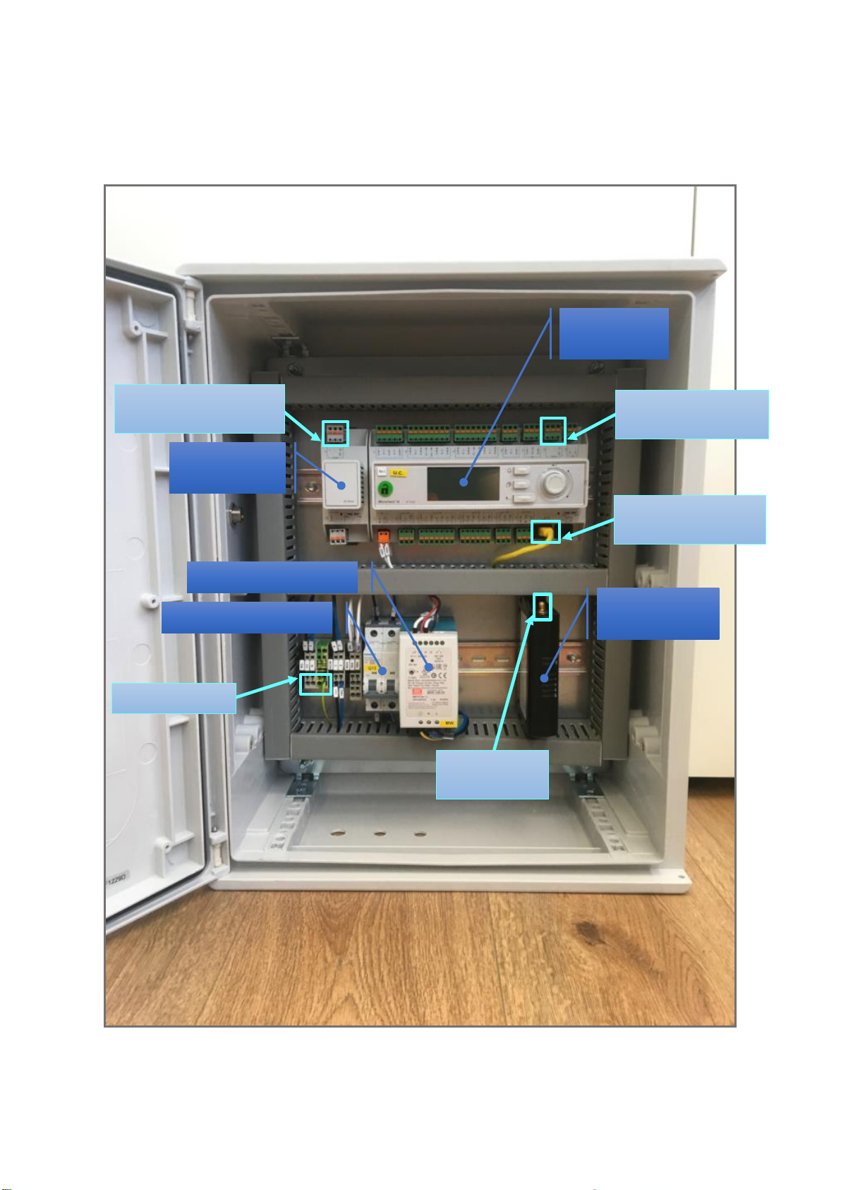
Device Overview
Below is reported a picture that shows how is made the new ALC DC8. In particular, the components
and devices used so far (blue) are reported in this paragraph and the new connections requested (light
blue) are described in paragraph ALC connection diagram.
The ALC DC8 is mainly composed of the following devices:
➢ Power supply - a MDR-100-24 Meanwell power supply units that can be input powered at 85
VAC to 264 VAC or 120 VDC to 370 VDC and provide output up to 96W 24V 4A. A bit
“oversized” to powering all the currently foreseen devices and in future any additional
modules.
➢ Main On/Off Switch - to power on/off all the devices within the ALC DC8 cabinet.
➢ Main MTIII controller - a POL687.70 which also guarantees good HW and SW potential
growth.
➢ (Optional) M2M Kit – a Teltonika RUT240 in case of 4G connection.
➢ (Optional) BMS Communication Module - POL902 in case of BMS Modbus connection,
POL908 in case of BMS BacNet connection.
Page 10
Installation and Operation Manual D-EIOCP00206-20_00EN
10/76
ALC-DC8
➢ MTII Modbus communication serial card – even if not shown in the overview image, it is
necessary to install on the MTII a serial card for Modbus communication (if not already
installed) between ALC DC8 and MTII. The referenced model is the Carel EKAC200J.
Figure 1: ALC DC8 main components
Power Supply
(Optional)
BMS Module
Main On/Off Switch
(Optional) 4G
Modem
MTIII
Controller
1) Power Cable
2) Modbus cable
(MTII Communication)
3) Ethernet cable
(DoS Connection)
4) ModBus/Bacnet cable
(BMS Communication)
5) 4G Antenna
SMA connector
Page 11
ALC-DC8
Installation and Operation Manual D-EIOCP00206-20_00EN
11/76
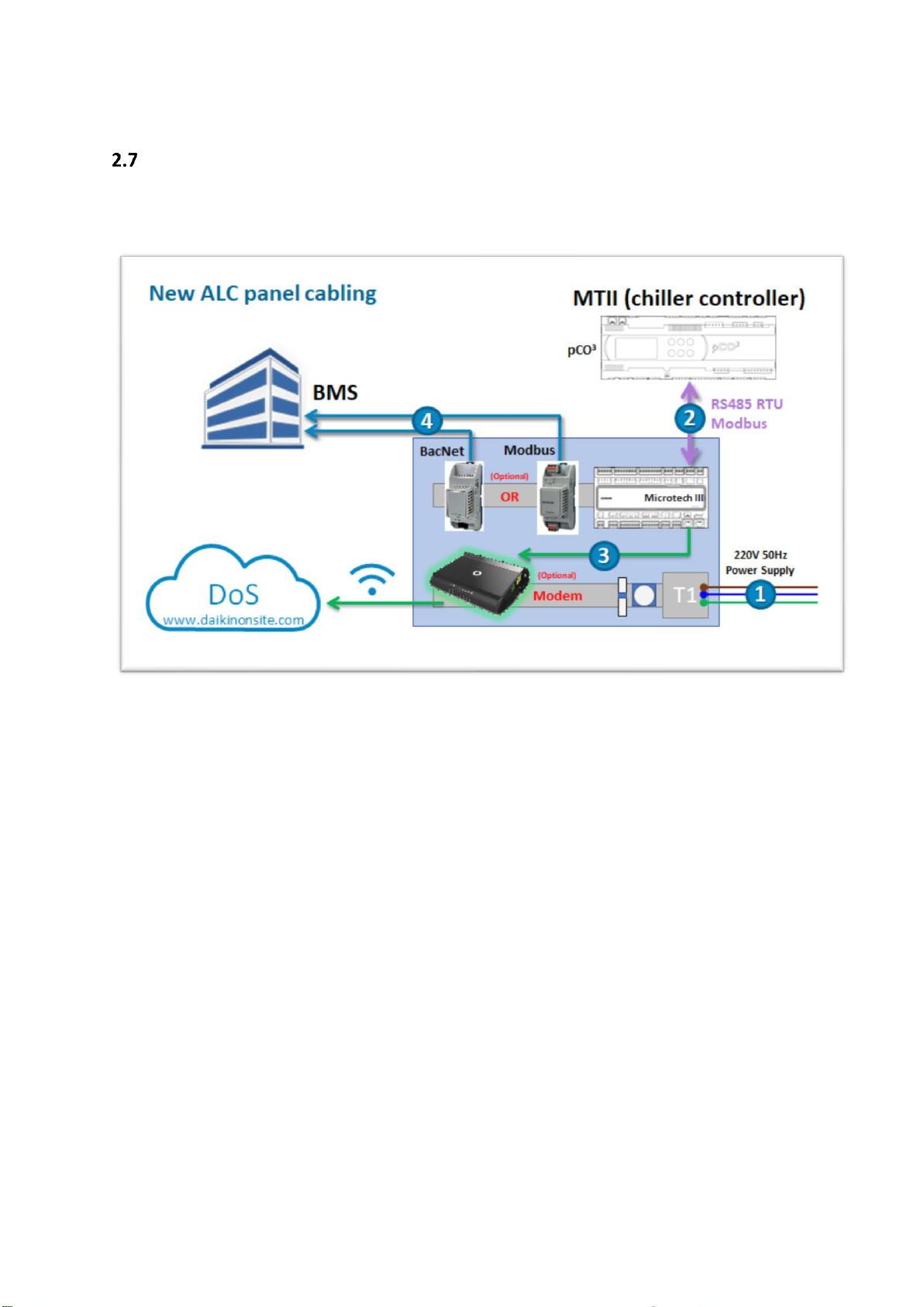
ALC connection diagram
The ALC DC8 provides new diagram connections as shown in the following figure. With respect to the
previous versions of ALC, the internal MTIII controller now manages every communication.
Figure 2: ALC DC8 connection diagram
As reported in the diagram, excluding the power supply cable, the type connections are mainly 5. With
reference to the numbering also used in the ALC overview image, these are:
1. The new ALC operates with a single-phase power supply (100→240VAC, 50/60Hz)
2. The main communication connection, always provided, is a 3-wire cable (+ / - / Gnd ref) that
allows the ALC to communicate with the MTII of the chiller unit via RS485 RTU Modbus
protocol.
3. An ethernet cable that allows the ALC to reach the networks and so Daikin On Site. Optionally
a 4G modem can be requested for a wireless connection.
4. (Optional) In case of link to BMS through optional POL modules, a cable that allow the ALC to
communicate with the BMS itself by means of Bacnet IP or Modbus RS485 connection.
5. (Optional) In case of 4G modem, an external antenna can improve the reception of the signal.
It is strongly antenna suggested to use a high gain external 4G if you are in an ambient that is
not easily reachable by the 4G signal to avoid sporadic and inefficient communications.
Page 12
Installation and Operation Manual D-EIOCP00206-20_00EN
12/76
ALC-DC8
3 Using the Controller
Knowing how to use the control system is necessary for a correct use of the same, as well as to
complete the installation as indicated in the subsequent chapters or to carry out maintenance
operations.
The control system consists of a unit controller (UC) to which can be connected POL extension modules
or other devices that implement additional features. All POL modules communicate via an internal
peripheral bus with the UC. The Microtech III continuously manages the information received from
these devices. The UC incorporates a program that controls the unit.
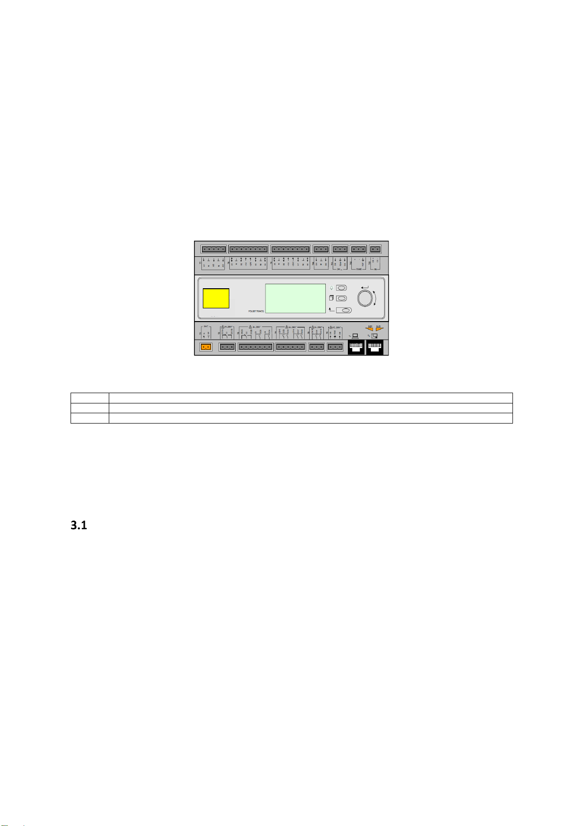
The standard HMI consists of an inbuilt display (A) with 3 buttons (B) and a push’n’roll control (C).
The keypad/display (A) consists of a 5-line by 22 character display. The function of the three buttons
(B) is described below:
Alarm status (from any page it links with the page with alarm list, alarm log and alarm snapshot if available)
Back to Main Page
Back to the previous level (it can be the Main Page)
The push’n’roll command (C) is used to scroll between the different menu pages, settings and data
available on the HMI for the active password level. Rotating the wheel allows to navigate between
lines on a screen (page) and to increase and decrease changeable values when editing. Pushing the
wheel acts as an Enter Button and will jump from a link to the next set of parameters.
General Recommendation
Before switching on the unit read the following recommendations:
• When all the operations and all the settings have been carried out, close all the switchbox
panels
• The switchbox panels can only be opened by trained personnel
• When the UC requires to be accessed frequently the installation of a remote interface is
strongly recommended
• The LCD display of the unit controller and other devices within the panel may be damaged by
extremely low temperatures. For this reason, it is strongly recommended to never power off
the unit during winter, especially in cold climates.
A
B
C
UC
Page 13

ALC-DC8
Installation and Operation Manual D-EIOCP00206-20_00EN
13/76
Navigating
When power is applied to the control circuit, the controller screen will be active and display the Home
screen, which can also be accessed by pressing the Menu Button The navigating wheel is the only
navigating device necessary, although the MENU, ALARM, and BACK buttons can provide shortcuts as
explained previously.
An example of the HMI screens is shown in the following picture.
M a i n M e n u 1 /
11
E n t e r P a s s w o r d
U n i t S t a t u s = O f f : U n i t S W
A c t i v e S e t p t = 7 . 0 °
C
A bell ringing in the top right corner will indicate an active alarm. If the bell doesn’t move it means
that the alarm has been acknowledged but not cleared because the alarm condition hasn’t been
removed. A LED will also indicate where the alarm is located between the unit or circuits.
M a i n M e n u 1 /
E n t e r P a s s w o r d
U n i t S t a t u s =
O f f : U n i t S W
A c t i v e S e t p t = 7 . 0 °
C
The active item is highlighted in contrast, in this example the item highlighted in Main Menu is a link
to another page. By pressing the push’n’roll, the HMI will jump to a different page. In this case the
HMI will jump to the Enter Password page.
E n t e r P a s s w o r d 2 / 2
E n t e r P W * * *
*
Passwords
The HMI structure is based on access levels that means that each password will disclose all the settings
and parameters allowed to that password level. Basic information about the status including the active
alarm list, active setpoint and controlled water temperature can be accessed without the need to
enter the password. At user level, UC handles one level of passwords:
MAINTENANCE
2526
The following information will cover all data and settings accessible with the maintenance password.
INFO: to access with higher level rights (i.e. Daikin Service role), please contact Daikin On Site
Smart Center to assess if possible (it is up to the membership of Daikin company).
In the Enter Password screen, the line with the password field will be highlighted to indicate that the
field on the right can be changed. This represents a setpoint for the controller. Pressing the push’n’roll
the individual field will be highlighted to allow an easy introduction of the numeric password. By
changing all fields, the 4 digits password will be entered and, if correct, the additional settings available
with that password level will be disclosed.
Page 14

Installation and Operation Manual D-EIOCP00206-20_00EN
14/76
ALC-DC8
E n t e r P a s s w o r d 2 /
2
E n t e r P W 5 * *
*
The password will time out after 10 minutes and is cancelled if a new password is entered or the
control powers down. Entering an invalid password has the same effect as continuing without a
password.
Once a valid password has been entered, the controller allows further changes and access without
requiring the user to enter a password until either the password timer expires or a different password
is entered. The default value for this password timer is 10 minutes. It is changeable from 3 to 30
minutes via the Timer Settings menu in the Extended Menus.
Editing
The Editing Mode is entered by pressing the navigation wheel while the cursor is pointing to a line
containing an editable field. Then:
• Once in the edit mode pressing the wheel again causes the editable field to be highlighted.
• Turning the wheel clockwise while the editable field is highlighted causes the value to be
increased.
• Turning the wheel counter-clockwise while the editable field is highlighted causes the value
to be decreased.
• The faster the wheel is turned the faster the value is increased or decreased.
• Pressing the wheel again cause the new value to be saved and the keypad/display to leave the
edit mode and return to the navigation mode.
• A parameter with an “R” is read only; it is giving a value or description of a condition.
• An “R/W indicates a read and/or write opportunity; a value can be read or changed (providing
the proper password has been entered).
Example 1: Check the Model name. Start at Main Menu and scroll down by means of wheel until the
submenu About Chiller is highlighted. There will be an arrow at the right side of the box, indicating
that a jump to the next level is possible. Press the wheel to execute the jump. You will arrive at About
Chiller link concerning info about the chiller itself and including the name of the model.
Example 2: Change a Set point, the Daikin On Site Communication Start for example. From the Main
Menu select View/Set Unit. The arrow indicated that this is link to a further menu. Press the wheel
and jump to the next menu View/Set Unit and use the wheel to scroll down to Daikin On Site. Select
the item “Comm Start” and press the wheel to jump to the item change page. Rotate the wheel to
adjust the set point to the desired value (Start). When this is done press the wheel again to confirm
the new value. With the Back button it will be possible to jump back to the Daikin On Site menu where
the new value will be displayed.
Page 15

ALC-DC8
Installation and Operation Manual D-EIOCP00206-20_00EN
15/76
Example 3: Clear Alarms. The presence of a new alarm is indicated with a Bell ringing on the top right
of the display. If the Bell is frozen one or more alarm had been acknowledged but are still active. To
view the Alarm menu from the Main Menu, scroll down to the Alarms line or simply press the Alarm
button on the display. Note the arrow indicating this line is a link. Press the wheel to jump to the next
menu Alarms There are some lines her: Alarms are cleared from the Active Alarm link. Press the wheel
to jump to the next screen. Then press again the wheel on Acknowledge. Change this value to Execute
to acknowledge the alarms. If the alarms can be cleared, then the alarm counter will display 0
otherwise it will display the number of alarms still active. When the alarms are acknowledged the Bell
on the top right of the display will stop to ring if some of the alarms are still active or will disappear if
all the alarms are cleared.
Basic Control System Diagnostic
MicroTech III controller, extension modules and communication modules are equipped with two
status LED (BSP and BUS) to indicate the operational status of the devices. The BUS LED indicates the
status of the communication with the controller. The meaning of the two status LED is indicated
below.
Main Controller (UC)
BSP LED
Mode
Solid Green
Application running
Solid Yellow
Application loaded but not running (*) or BSP Upgrade mode active
Solid Red
Hardware Error (*)
Flashing Green
BSP startup phase. The controller needs time for starting.
Flashing Yellow
Application not loaded (*)
Flashing Yellow/Red
Fail safe mode (in case that the BSP upgrade was interrupted)
Flashing Red
BSP Error (software error*)
Flashing Red/Green
Application/BSP update or inizialization
(*) Contact Service.
Extension modules (currently not used for ALC)
BSP LED
Mode
BUS LED
Mode
Solid Green
BSP running
Solid Green
Communication running, I/O working
Solid Red
Hardware Error (*)
Solid Red
Communication down (*)
Flashing Red
BSP Error (*)
Solid Yellow
Communication running but parameter from the
application wrong or missing, or uncorrect factory
calibration
Flashing Red/Green
BSP upgrade mode
Communication modules
BSP LED (same for all modules)
BSP LED
Mode
Solid Green
BPS running, communication with controller
Solid Yellow
BSP running, no communication with controller (*)
Solid Red
Hardware Error (*)
Flashing Red
BSP Error (*)
Flashing Red/Green
Application/BSP update
(*) Contact Service.
Page 16
Installation and Operation Manual D-EIOCP00206-20_00EN
16/76
ALC-DC8
BUS LED
BUS LED
Bacnet IP
Modbus
Solid Green
Ready for Communication. The BACnet Server is
started. It doesn't indicate an active communication
All Communication running
Solid Yellow
Startup. The LED stays yellow until the module
receives a IP Address, therefore a link must be
established.
Startup, or one configured channel not communicating to
the Master
Solid Red
BACnet Server down. Automatic restart after 3
seconds is initiated.
All configured Communications down. Means no
communication to the Master. The timeout can be
configured. In case that the timeout is zero the timeout is
disabled.
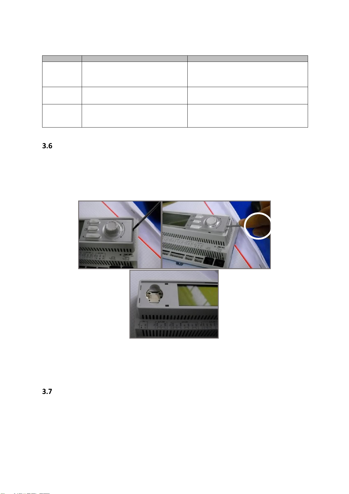
Controller maintenance
The controller requires to maintain the installed battery. Every two years it’s required to replace the
battery. Battery model is: BR2032 and it is produced by many different vendors.
To replace the battery, remove the plastic cover of the controller display using a screw driver as shown
in the following pictures:
Be careful to avoid damages to the plastic cover. The new battery shall be placed in the proper battery
holder, which is highlighted in the following picture, respecting the polarities indicated into the holder
itself.
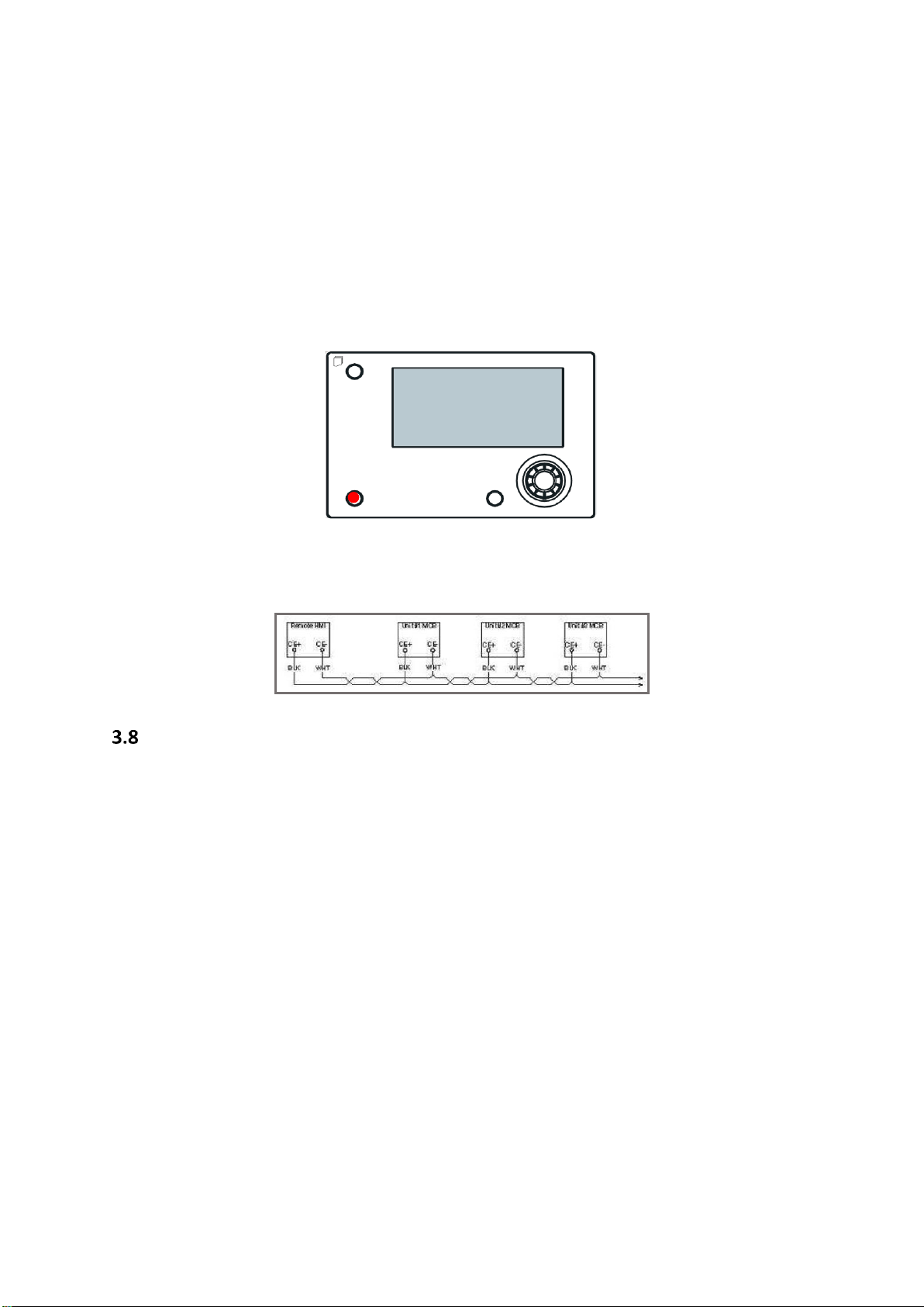
Optional Remote User Interface
As an option an external Remote HMI can be connected on the UC. The Remote HMI offers the same
features as the inbuilt display plus the alarm indication done with a light emitting diode located below
the bell button.
Page 17
ALC-DC8
Installation and Operation Manual D-EIOCP00206-20_00EN
17/76
The Remote can be ordered with the unit and shipped loose as a field installed option. It can also be
ordered any time after chiller shipment and mounted and wired on the job as explained on the
following page. The remote panel is powered from the unit and no additional power supply is
required.
All viewing and setpoint adjustments available on the unit controller are available on the remote
panel. Navigation is identical to the unit controller as described in this manual.
The initial screen when the remote is turned on shows the units connected to it. Highlight the desired
unit and press the wheel to access it. The remote will automatically show the units attached to it, no
initial entry is required.
The Remote HMI can be extended up to 700m using the process bus connection available on the UC.
With a daisy-chain connection as below, a single HMI can be connected to up to 8 units. Refer to the
specific HMI manual for details.
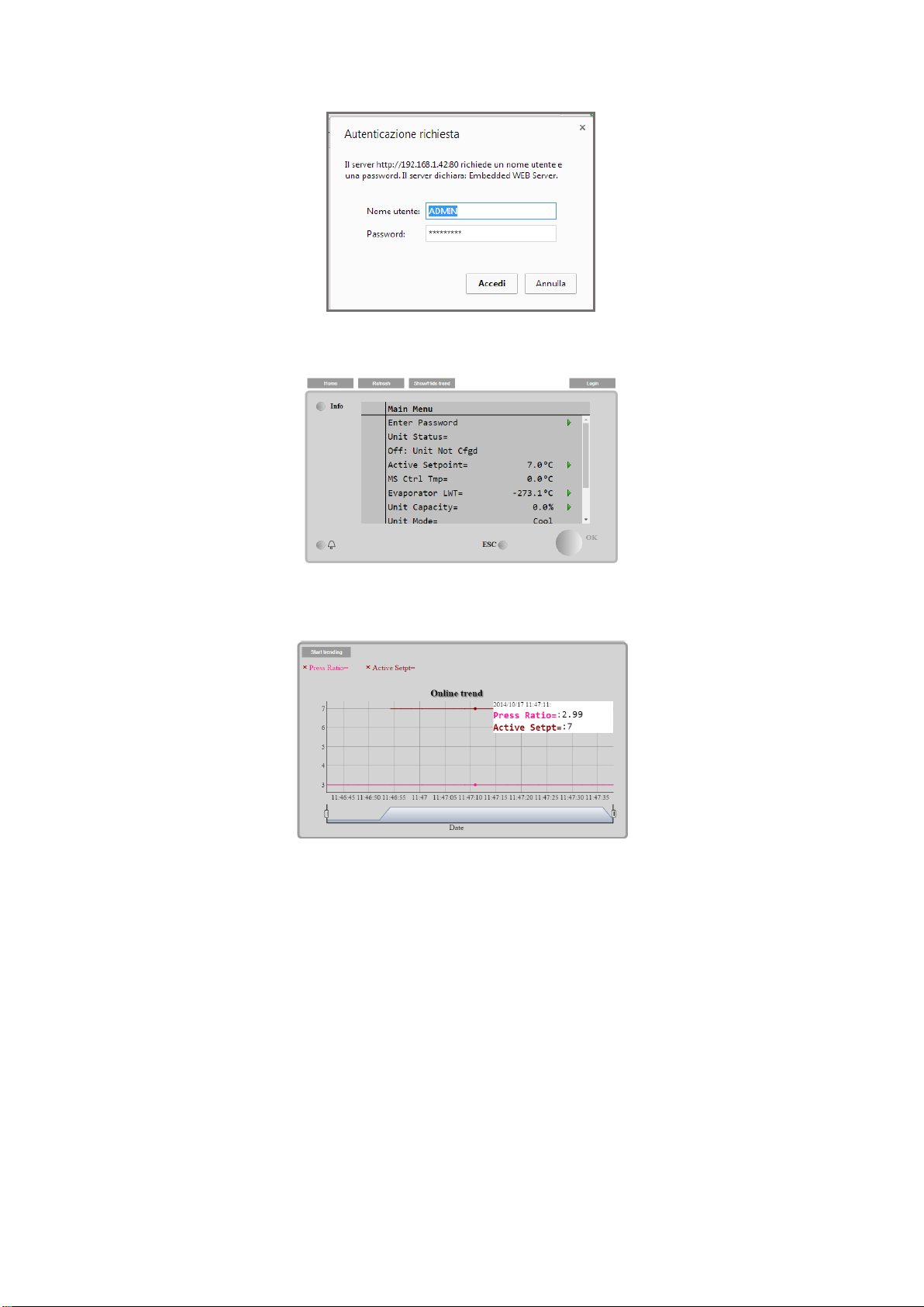
Embedded Web Interface
The MicroTech III controller has an embedded web interface that can be used to monitor the unit
when connected to a local network. It is possible to configure the IP addressing of the MicroTech III as
a fixed IP of DHCP depending on the network configuration.
With a common web browser, a PC can connect with the unit controller entering the IP address of the
controller or the host name, both visible in the “About Chiller” page accessible without entering a
password. When connected, it will be required to enter a username and a password. Enter the
following credential to get access to the web interface:
User Name: ADMIN
Password: SBTAdmin!
MicroTech® III
Page 18
Installation and Operation Manual D-EIOCP00206-20_00EN
18/76
ALC-DC8
The Main Menu page will be displayed. The page is a copy of the onboard HMI and follows the same
rules in terms of access levels and structure.
In addition, it allows to trend log a maximum of 5 different quantities. It’s required to click on the
value of the quantity to monitor and the following additional screen will become visible:
Depending on the web browser and its version the trend log feature may not be visible. It’s required
a web browser supporting HTML 5 like for example:
• Google Chrome v.37,
• Mozilla Firefox v.32.
These browsers are only an example of the supported ones and the versions indicated have to be
intended as minimum versions.
Page 19
ALC-DC8
Installation and Operation Manual D-EIOCP00206-20_00EN
19/76
4 Menu Structure
All settings are divided in different menus. Each menu collects in a single page other sub-menus,
settings or data related to a specific function (for example Power Conservation or Setup) or entity (for
example Unit or Circuit). In any of the following pages a grey box will indicate changeable values and
the defaults.
The submenu items to which a user can have access, depend upon his role and the password entered
as described in the paragraph dedicated to Passwords.
Main Menu
Setpoint/Sub-Menu
Default
Range
Description
Enter Password
-
Submenu to activate access levels
View/Set Unit
-
Submenu for unit data and settings
View/Set Circuit
-
Submenu for circuit data and settings
Unit Status=
NULL
NULL, 1, 2, 3, 4, 5, 6, 7, 8, 9, 10, 11, 12,
13, 14, 15, 16
Status of the Unit
Active Setpoint=
0°C,
-
Water temperature active setpoint + link to Setpoint page
Actual Capacity=
0.0%,
-
Unit capacity + link to “Capacity” page
Evaporator LWT=
-273.1°C,
-
Evaporator leaving water temperature + link to
“Temperatures” page
Unit Mode=
NULL
NULL,
Ice,
Cool,
Heat
Unit Mode
Alarms
-
Submenu for alarms; same function as Bell Button
Commission Unit
-
Submenu for commission unit
Diagnostic
-
Submenu for diagnostic
About Chiller
-
Application Info submenu
4.1.1 View/Set Unit
Setpoint/Sub-Menu
Default
Range
Description
Thermostat Ctrl
-
Submenu for Thermostatic control
Network Ctrl
-
Submenu for Network control
Pumps
-
Submenu for pump settings
Date/Time Schedules
-
Submenu Date, Time and Quiet Night mode schedule
Power Conservation
-
Submenu Unit Limiting functions
Ctrlr IP Setup
-
Submenu for controller IP-address setup
Daikin on Site
-
Submenu for connection to Daikin cloud DoS
Modbus
-
Submenu for Modbus configuration (only with inserted CommCard)
BACnetIP
-
Submenu for BACnetIP configuration (only with inserted CommCard)
4.1.1.1 Thermostat Ctrl
This page resumes all the parameters related to the unit thermostatic control.
Setpoint/Sub-Menu
Default
Range
Description
MCQ
USA
Start DT=
2.5°C - -64…64°C
Offset to start thermostat control
Stop DT=
2.0°C - -64…64°C
Offset to stop thermostat control
Stop to start=
180s - 0…3600s
Compressor stop delay before start
Page 20
Installation and Operation Manual D-EIOCP00206-20_00EN
20/76
ALC-DC8
4.1.1.2 Network Ctrl
This page resumes all settings related to Network control.
Setpoint/Sub-Menu
Default
Range
Description
MCQ
USA
Control Source=
Supervisor
On/Off
Supervisor
On/Off
Supervisor
On/Off possible,
Supervisor
On/Off NOT
possible,
NULL
Local Network control selection
Netwrk En SP=
Require
Unit OFF
Require
Unit OFF
Require Unit OFF,
Require Unit ON,
NULL
Enable unit command from BMS
Netwrk Mode SP=
Cool
Cool
Null,
Ice,
Cool,
Heat
HVAC mode
Netwrk Cap Lim=
100%
100%
0…100%
Capacity limitation from BMS
Netwrk Ice SP=
-
-3.8°C
-10…10°C
Ice setpoint from BMS
4.1.1.3 Pumps
This page resumes all settings related to the unit pumps.
Setpoint/Sub-Menu
Default
Range
Description
MCQ
USA
E. Pump 1 RH=
0 h - -64…64h
Run hours of evaporator pump #1
C. Pump 1 RH=
0 h - -64…64h
Run hours of condenser pump #1
Evap Pump 1 RH=
-
0 h
-64…64h
Run hours of evaporator pump #1
Cond Pump 1 RH=
-
0 h
-64…64h
Run hours of condenser pump #1
Evap Pump 2 RH=
-
0 h
-64…64h
Run hours of evaporator pump #2
Cond Pump 2 RH=
-
0 h
-64…64h
Run hours of condenser pump #2
4.1.1.4 Date/Time Schedules
This page resumes all settings related to daylight saving (DLS) mode.
Setpoint/SubMenu
Default
Range
Description
MCQ
USA
Actual Time=
hh:mm:ss
hh:mm:ss
-
Current time
Actual Date=
Mm/dd/yyyy
Mm/dd/yyyy
-
Current date
UTC Diff=
-60 min
-60 min
-
Difference from UTC
DLS Enable=
Yes
Yes
Yes, No
Daylight saving enable setpoint
DLS Strt Month=
3 3 1…12
Daylight saving start month
DLS Strt Week=
6 6 0…6
Daylight saving start weekday. Numbers between 0 and 6, where 0
is Monday and 6 is Sunday
DLS End Month=
10
10
1…12
Daylight saving end month
DLS End Week=
6 6 0…6
Daylight saving end weekday
4.1.1.5 Power Conservation
This page resumes all settings related to unit limiting functions.
Setpoint/Sub-Menu
Default
Range
Description
MCQ
USA
Unit Capacity=
0%
0%
-64…64%
Unit capacity actual value
Demand Limit=
0%
0%
-64…64%
Demand limit value
Page 21

ALC-DC8
Installation and Operation Manual D-EIOCP00206-20_00EN
21/76
4.1.1.6 Ctrlr IP Setup
This page resumes all settings and data related to controller IP-address setup
Setpoint/SubMenu
Default
Range
Description
MCQ
USA
Apply Changes=
Off
Off
On, Off
Command to restart the controller
DHCP=
On
On
On Off
Enable DHCP to assign controller IP address
M2M Modem=
None
None
None
MachineLink
Teltonika
Type of M2M device
Act IP=
192.168.1.42
192.168.1.42
0…255
Actual IP address assigned to controller
Act Msk=
255.255.255.0
255.255.255.0
0…255
Actual IP address assigned to network subnet mask
Act Gwy=
192.168.1.1
192.168.1.1
0…255
Actual IP address assigned to gateway
Gvn IP=
192.168.1.42
192.168.1.42
0…255
Given IP address setpoint to be assigned to controller
Gvn Msk=
255.255.255.0
255.255.255.0
0…255
Given IP address setpoint to be assigned to subnet mask
Gvn Gwy=
192.168.1.1
192.168.1.1
0…255
Given IP address setpoint to be assigned to gateway
Prim DNS=
192.168.1.1
192.168.1.1
0…255
Primary DNS IP address
Sec DNS=
0.0.0.0
0.0.0.0
0…255
Secondary DNS IP address
Host Name=
POL**********
POL**********
-
Hostname for the controller inside the network
MAC
xx-xx-xx-xx-xxxx
xx-xx-xx-xx-xxxx
x=0…9, A...Z
Controller MAC address
4.1.1.7 Daikin On Site
This page resumes all settings related to connect the controller to Daikin cloud DoS
Setpoint/SubMenu
Default
Range
Description
MCQ
USA
Comm Start=
Start
Start
Off, Start
Command to enable communication with Daikin cloud
Comm State=
- - - ,
IPErr,
Init,
InitErr,
Reg,
RegErr,
Description,
Connected
State of the communication with cloud
Serial Number=
xxxxx
xxxxx
x=0…9
Unique serial number of the controller. The serial number can be
composed by four or five numbers.
Activation Key=
xxxxxx- xxxxxxxxxx- xxxxxxxxxx
xxxxxx- xxxxxxxxxx- xxxxxxxxxx
x=1…9, A…Z
Unique alphanumeric key of 26 characters to register the controller
in the cloud platform
4.1.2 View/Set Circuit
Setpoint/SubMenu
Default
Range
Description
MCQ
USA
C1
-
Link for Circuit #1 page
C2 - - Link for Circuit #2 page
C3 - - Link for Circuit #3 page
C4 -
-
Link for Circuit #4 page
4.1.2.1 View/Set Cir-X
This page resumes all settings and data related to the Circuit number “-X”, where X = 1,2,3,4.
Setpoint/Sub-Menu
Default
Range
Description
MCQ
USA
Data=
-
Link for “Data” page
Compressor=
-
Link for “Compressor” page
Condenser=
-
Link for “Condenser” page
EXV=
-
Link for “EXV” page
Page 22

Installation and Operation Manual D-EIOCP00206-20_00EN
22/76
ALC-DC8
4.1.2.2 Data
This page resumes all main settings and data for the selected circuit.
Setpoint/Sub-Menu
Default
Range
Description
MCQ
USA
Circuit Status=
-
Link for “Circuit Status”
Capacity=
0%,
0%
-64…64%
Actual capacity of the unit
Evap Press=
0 bar,
-
-64…64 bar
Current evaporator pressure
Evap Press 1=
-
0 bar
-64…64 bar
Current evaporator pressure from probe#1
Evap Press 2=
-
0 bar
-64…64 bar
Current evaporator pressure from probe#2
Cond Press=
0 bar,
-
-64…64 bar
Current condenser pressure
Cond Press 1=
-
0 bar
-64…64 bar
Current condenser pressure from probe#1
Cond Press 2=
-
0 bar
-64…64 bar
Current condenser pressure from probe#2
Evap Sat Temp=
0°C,
-
-64…64°C
Current evaporator saturated temperature
Evap Sat Temp 1=
-
0°C
-64…64°C
Current evaporator saturated temperature from probe#1
Evap Sat Temp 2=
-
0°C
-64…64°C
Current evaporator saturated temperature from probe#2
C. Sat Tmp=
0°C,
-
-64…64°C
Current condenser saturated temperature
C. Sat Tmp 1=
-
0°C
-64…64°C
Current condenser saturated temperature from probe#1
C. Sat Tmp 2=
-
0°C
-64…64°C
Current condenser saturated temperature from probe#2
Suct Temp=
0°C,
-
-64…64°C
Current value of suction temperature
Suct Temp 1=
- -64…64°C
Current value of suction temperature from probe#1
Suct Temp 2=
-
0°C
-64…64°C
Current value of suction temperature from probe#2
Disch Temp=
0°C,
-
-64…64°C
Current value of discharge temperature
Disch Temp 1=
-
0°C
-64…64°C
Current value of discharge temperature from probe#1
Disch Temp 2=
-
0°C
-64…64°C
Current value of discharge temperature from probe#2
Oil Press=
0 bar,
-
-64…64 bar
Current value of oil pressure
EXV Position
0 steps,
-
-64…64 steps
Current value of expansion valve position
Evap LWT=
0°C
0°C
-64…64°C
Current value of water temperature entering the evaporator
Evap EWT=
0°C
0°C
-64…64°C
Current value of water temperature leaving the evaporator
Circuit Status
This page resumes the current state of the circuit, for each circuit.
Setpoint/SubMenu
Default
Range
Description
MCQ
USA
C1=
NULL
NULL
NULL*1*2*3*4*5*6*7*8*9*10*
*11*12*13*14*15*16*17*18*19*20*21*22
Circuit status value for Circuit#1
C2=
NULL - NULL*1*2*3*4*5*6*7*8*9*10*
*11*12*13*14*15*16*17*18*19*20*21*22
Circuit status value for Circuit#2
C3=
NULL - NULL*1*2*3*4*5*6*7*8*9*10*
*11*12*13*14*15*16*17*18*19*20*21*22
Circuit status value for Circuit#3
C4=
NULL - NULL*1*2*3*4*5*6*7*8*9*10*
*11*12*13*14*15*16*17*18*19*20*21*22
Circuit status value for Circuit#4
Capacity
This page resumes all the capacity value of the circuit, for each circuit.
Setpoint/Sub-Menu
Default
Range
Description
MCQ
USA
C1=
0% - -64…64%
Capacity value for Circuit#1
C2=
0% - -64…64%
Capacity value for Circuit#2
C3=
0% - -64…64%
Capacity value for Circuit#3
C4=
0% - -64…64%
Capacity value for Circuit#4
Evap Pressure
This page resumes all the evaporator pressures of each circuit.
Setpoint/Sub-Menu
Default
Range
Description
MCQ
USA
C1=
0 bar - -64…64 bar
Evaporator pressure for Circuit#1
C2=
0 bar - -64…64 bar
Evaporator pressure for Circuit#2
C3=
0 bar - -64…64 bar
Evaporator pressure for Circuit#3
C4=
0 bar - -64…64 bar
Evaporator pressure for Circuit#4
Page 23

ALC-DC8
Installation and Operation Manual D-EIOCP00206-20_00EN
23/76
Cond Pressure
This page resumes all the condenser pressures of each circuit.
Setpoint/Sub-Menu
Default
Range
Description
MCQ
USA
C1=
0 bar - -64…64 bar
Condenser pressure for Circuit#1
C2=
0 bar - -64…64 bar
Condenser pressure for Circuit#2
C3=
0 bar - -64…64 bar
Condenser pressure for Circuit#3
C4=
0 bar - -64…64 bar
Condenser pressure for Circuit#4
Evap Sat Temp
This page resumes all the evaporator saturated temperatures of each circuit.
Setpoint/Sub-Menu
Default
Range
Description
MCQ
USA
C1=
0°C - -64…64°C
Evap. saturated temperature for Circuit#1
C2=
0°C - -64…64°C
Evap. saturated temperature for Circuit#2
C3=
0°C - -64…64°C
Evap. saturated temperature for Circuit#3
C4=
0°C - -64…64°C
Evap. saturated temperature for Circuit#4
C Sat Temp
This page resumes all the condenser saturated temperature, for each circuit.
Setpoint/Sub-Menu
Default
Range
Description
MCQ
USA
C1=
0°C - -64…64°C
Cond. saturated temperature for Circuit#1
C2=
0°C - -64…64°C
Cond. saturated temperature for Circuit#2
C3=
0°C - -64…64°C
Cond. saturated temperature for Circuit#3
C4=
0°C - -64…64°C
Cond. saturated temperature for Circuit#4
Suct Temp
This page restores all the suction temperatures of each circuit.
Setpoint/Sub-Menu
Default
Range
Description
MCQ
USA
C1=
0°C - -64…64°C
Suction temperature for Circuit#1
C2=
0°C - -64…64°C
Suction temperature for Circuit#2
C3=
0°C - -64…64°C
Suction temperature for Circuit#3
C4=
0°C - -64…64°C
Suction temperature for Circuit#4
Disch Temp
This page resumes all the discharge temperatures of each circuit.
Setpoint/Sub-Menu
Default
Range
Description
MCQ
USA
C1=
0°C - -64…64°C
Discharge temperature for Circuit#1
C2=
0°C - -64…64°C
Discharge temperature for Circuit#2
C3=
0°C - -64…64°C
Discharge temperature for Circuit#3
C4=
0°C - -64…64°C
Discharge temperature for Circuit#4
Oil Pressure
This page resumes all the oil pressures of each circuit.
Setpoint/Sub-Menu
Default
Range
Description
MCQ
USA
C1=
0 bar - -64…64 bar
Oil pressure for Circuit#1
C2=
0 bar - -64…64 bar
Oil pressure for Circuit#2
C3=
0 bar - -64…64 bar
Oil pressure for Circuit#3
C4=
0 bar - -64…64 bar
Oil pressure for Circuit#4
Page 24

Installation and Operation Manual D-EIOCP00206-20_00EN
24/76
ALC-DC8
EXV Position
This page resumes all data relating to the expansion valve position, for each circuit.
Setpoint/Sub-Menu
Default
Range
Description
MCQ
USA
C1=
0steps,
-
-64…64 steps
EXV position for Circuit#1
C2=
0steps,
-
-64…64 steps
EXV position for Circuit#2
C3=
0steps,
-
-64…64 steps
EXV position for Circuit#3
C4=
0steps,
-
-64…64 steps
EXV position for Circuit#4
4.1.2.3 Compressor
This page resumes all main settings and data related to the compressor of selected circuit.
Setpoint/Sub-Menu
Default
Range
Description
MCQ
USA
No. Starts=
0,
0,
-64…64
Number of starts of compressor for selected circuit + Link to “No.
Starts” page
Run Hours=
0h,
0h,
-64…64 h
Run hours of compressor for selected circuit + Link to “Run Hours”
page
Capacity=
0%,
-
-64…64%
Capacity of selected circuit + Link to “Capacity” page
Load St=
Unit not
required
to load
-
Unit not required
to load,
Unit required to
load,
NULL
Load state of compressor for selected circuit
Unload St=
Unit not
required
to unload
-
Unit not required
to unload,
Unit required to
unload,
NULL
Unload state of compressor for selected circuit
No. Starts
This page resumes all the number of starts of compressor.
Setpoint/Sub-Menu
Default
Range
Description
MCQ
USA
C1= 0 0
-64…64
Number of starts of compressor for Circuit#1 (MCQ); Number of
starts of compressor#1 for Circuit#1 (USA);
C2= 0 0
-64…64
Number of starts of compressor for Circuit#2 (MCQ); Number of
starts of compressor#2 for Circuit#1 (USA);
C3= 0 -
-64…64
Number of starts of compressor for Circuit#3 (MCQ)
C4= 0 -
-64…64
Number of starts of compressor for Circuit#4 (MCQ)
Run Hours
This page resumes all the run hours of compressor.
Setpoint/Sub-Menu
Default
Range
Description
MCQ
USA
C1=
0h
0h
-64…64 h
Run hours of compressor for Circuit#1 (MCQ); Run hours of
compressor#1 for Circuit#1 (USA);
C2=
0h
0h
-64…64 h
Run hours of compressor for Circuit#2 (MCQ); Run hours of
compressor#2 for Circuit#1 (USA);
C3=
0h - -64…64 h
Run hours of compressor for Circuit#3 (MCQ)
C4=
0h - -64…64 h
Run hours of compressor for Circuit#4 (MCQ)
Page 25

ALC-DC8
Installation and Operation Manual D-EIOCP00206-20_00EN
25/76
4.1.2.4 Condenser
This page resumes all main settings and data related to the condenser of the selected circuit.
Setpoint/Sub-Menu
Default
Range
Description
MCQ
USA
C. Sat Tmp=
0°C,
-
-64…64°C
Saturated temperature of condenser for the selected circuit + Link to
“C Sat Temp” page
Cond Press=
0 bar,
-
-64…64 bar
Condenser pressure for the selected circuit + Link to “Cond Press”
page
C. Sat Tmp 1=
-
0°C
-64…64°C
Saturated temperature of condenser related to compressor#1 (single
circuit)
Cond Press 1=
-
0 bar
-64…64 bar
Condenser pressure related to compressor#1 (single circuit)
C. Sat Tmp 2=
-
0°C
-64…64°C
Saturated temperature of condenser related to compressor#2 (single
circuit)
Cond Press 2=
-
0 bar
-64…64 bar
Condenser pressure related to compressor#2 (single circuit)
4.1.2.5 EXV
This page resumes all main settings and data relating to the expansion valve.
Setpoint/Sub-Menu
Default
Range
Description
MCQ
USA
EXV Position=
0 steps,
-
-64…64 steps
Position of EXV and link to “EXV Position” page
Evap Press=
0 bar,
-
-64…64 bar
Evaporator pressure and link to “Evap Pressure” page
4.1.3 Active Setpoint
4.1.3.1 Tmp Setpoint
This page resumes all settings to configure the leaving water temperatures setpoints.
Setpoint/Sub-Menu
Default
Range
Description
MCQ
USA
Cool LWT
7.0°C
6.7°C
-64…64°C
Leaving water temperature setpoint for cooling mode
Heat LWT
45.0°C
50.0°C
-64…70°C
Leaving water temperature setpoint for heating mode
Ice LWT
-
-3.8°C
-10…10°C
Leaving water temperature setpoint for ice mode
4.1.4 Commission Unit
4.1.4.1 Configuration
Unit
This page resumes all settings to configure the unit.
Setpoint/Sub-Menu
Default
Range
Description
MCQ
USA
Unit Type=
Select
Unit
Name
Select
Unit
Name
PFS
ALS
WHS
MCAIR
MTM
WSC
WDC
WPV
WCC
HSC
TSC
HDC
WMC
Select Unit Name
Setpoint for specifying the unit model to which ALC device is
connected.
Page 26

Installation and Operation Manual D-EIOCP00206-20_00EN
26/76
ALC-DC8
No. Of Compr.=
0 0 0, 1, 2, 3, 4
Setpoint to configure the number of:
• compressors (USA)
• circuits (MCQ)
Write Enable=
Write Sp
Disabled
Write Sp
Disabled
Write Sp Disabled,
Write Sp from DoS,
Write Sp from BMS
Setpoint to enable editing/writing of all setpoint (sp) values.
Setp Values=
Copy
Values
MT2
Copy
Values
MT2
Copy Values MT2,
ALC default or MT3
Setpoint to choose the current values of all setpoints.
MB Comm Time Int=
5.0s
5.0s
-64…64s
Setpoint to setup the time interval of MODBUS communication
protocol.
MB Comm State=
-
-
Ok, Communication
ERROR!
Information on the state of MODBUS communication protocol.
Modem
This page resumes all settings and data related to the Circuit number “-X”, where X = 1,2,3,4.
Setpoint/Sub-Menu
Default
Range
Description
MCQ
USA
Modem=
None
None
None,
MachineLink,
Teltonika
Setpoint to configure the modem model, when the unit is
connected to Internet with a M2M device.
4.1.4.2 Calibrate Sensors
This page resumes all data relating to the sensors installed on the chiller unit.
Setpoint/Sub-Menu
Default
Range
Description
MCQ
USA
Unit=
-
Submenu with information on the unit sensors.
C1=
-
Submenu with information on the Circuit#1.
C2= - - Submenu with information on the Circuit#2
C3= - - Submenu with information on the Circuit#3
C4= - - Submenu with information on the Circuit#4
Unit
This page resumes all information about unit sensors.
Setpoint/Sub-Menu
Default
Range
Description
MCQ
USA
Evap EWT=
0°C
0°C
-64…64°C
Current value of evaporator entering water temperature
Evap LWT=
0°C
0°C
-64…64°C
Current value of evaporator leaving water temperature
Cond EWT=
0°C
0°C
-64…64°C
Current value of condenser entering water temperature
Cond EWT=
0°C
0°C
-64…64°C
Current value of condenser leaving water temperature
Heat Rec EWT=
0°C - -64…64°C
Current value of heat recovery entering water temperature
Heat Rec LWT
0°C - -64…64°C
Current value of heat recovery leaving water temperature
C-X
This page resumes all information about circuit sensors for the circuit number X, where X=1,2,3,4.
Setpoint/Sub-Menu
Default
Range
Description
MCQ
USA
Evap Press=
0 bar - -64…64 bar
Current value of evaporator refrigerant pressure for the selected
circuit
Cond Press=
0 bar - -64…64 bar
Current value of condenser refrigerant pressure for the selected
circuit
Oil Press=
0 bar - -64…64 bar
Current value of oil pressure for the selected circuit
Suct Temp=
0°C - -64…64°C
Current value of suction temperature for the selected circuit
Disch Temp=
0°C - -64…64°C
Current value of discharge temperature for the selected circuit
Evap Press 1=
-
0 bar
-64…64 bar
Current value of evaporator refrigerant pressure, related to the
compressor#1 (single circuit)
Evap Press 2=
-
0 bar
-64…64 bar
Current value of evaporator refrigerant pressure, related to the
compressor#2 (single circuit)
Cond Press 1=
-
0 bar
-64…64 bar
Current value of condenser refrigerant pressure, related to the
compressor#1 (single circuit)
Page 27

ALC-DC8
Installation and Operation Manual D-EIOCP00206-20_00EN
27/76
Cond Press 2=
-
0 bar
-64…64 bar
Current value of condenser refrigerant pressure, related to the
compressor#2 (single circuit)
Suct Temp 1=
-
0°C
-64…64°C
Current value of suction temperature, related to the compressor#1
(single circuit)
Suct Temp 2=
-
0°C
-64…64°C
Current value of suction temperature, related to the compressor#2
(single circuit)
Disch Temp 1=
-
0°C
-64…64°C
Current value of discharge temperature, related to the
compressor#1 (single circuit)
Disch Temp 2=
-
0°C
-64…64°C
Current value of discharge temperature, related to the
compressor#2 (single circuit)
4.1.4.3 Manual Control
This page resumes all setting for operating the unit manually.
Setpoint/Sub-Menu
Default
Range
Description
MCQ
USA
Unit=
-
Submenu with settings for the unit.
C1=
-
Submenu with settings for Circuit#1.
C2= - - Submenu with settings for Circuit#2.
C3= - - Submenu with settings for Circuit#3.
C4= - - Submenu with settings for Circuit#4.
Unit
This page resumes all information about the input/output state of unit probes and pumps.
Setpoint/Sub-Menu
Default
Range
Description
c
USA
Evap Flow Inp St=
Evaporator
flow present
Evaporator
flow present
Evaporator flow
present,
Evaporator flow
LOSS,
NULL
Status of the flow entering the evaporator.
Cond Flow Inp St=
Condenser
flow present
Condenser
flow present
Condenser flow
present,
Evaporator flow
LOSS,
NULL
Status of the flow entering the condenser.
E.Pmp1 Out St=
Main Pump
is OFF
Main Pump is
OFF
Main Pump is OFF,
Main Pump is ON,
NULL
Output status of the evaporator pump.
C.Pmp1 Out St=
Main Pump
is OFF
Main Pump is
OFF
Main Pump is OFF,
Main Pump is ON,
NULL
Output status of the condenser pump.
C-X
This page resumes all information about the fans state for the selected circuit.
Setpoint/Sub-Menu
Default
Range
Description
MCQ
USA
Fan 1 out st=
Fan #1 OFF
-
Fan #1 OFF
Fan #1 ON
NULL
Output state of fan#1 for the selected circuit. (MCQ only)
Fan 2 out st=
Fan #2 OFF
-
Fan #2 OFF
Fan #2 ON
NULL
Output state of fan#2 for the selected circuit. (MCQ only)
Fan 3 out st=
Fan #3 OFF
-
Fan #3 OFF
Fan #3 ON
NULL
Output state of fan#3 for the selected circuit. (MCQ only)
Fan 4 out st=
Fan #4 OFF
-
Fan #4 OFF
Fan #4 ON
NULL
Output state of fan#4 for the selected circuit. (MCQ only)
Fan 5 out st=
Fan #5 OFF
-
Fan #5 OFF
Fan #5 ON
NULL
Output state of fan#5 for the selected circuit. (MCQ only)
Fan 6 out st=
Fan #6 OFF
-
Fan #6 OFF
Fan #6 ON
Output state of fan#6 for the selected circuit. (MCQ only)
Page 28

Installation and Operation Manual D-EIOCP00206-20_00EN
28/76
ALC-DC8
NULL
4.1.5 Alarms
This page resumes all information about alarms.
Setpoint/Sub-Menu
Default
Range
Description
MCQ
USA
Alarm Active
-
Submenu with a list of currently active alarms.
Alarm History
-
Submenu with a list of all alarms.
Alarm Snapshot
-
Submenu with a list of alarm snapshot.
Advanced
-
Submenu with advanced options and information about alarms.
EventHistory
-
Submenu with a list of all events.
4.1.6 Diagnostic
This page resumes all information for the diagnostic of the controller.
Setpoint/Sub-Menu
Default
Range
Description
MCQ
USA
MT3 Run Hours=
x x x=0,1,2…
Operational time for MT3 controller.
Reset Cause=
Command
Command
Power,
Command,
Watchdog,
Unexpected
Event that restart the controller.
Nr. Of Reset=
x x x=0,1,2…
Counter for the number of controller reset
Internal Temp=
x x x=-64…64°C
Controller internal temperature
Mem. Used=
x x x=0…100%
Percentage of used memory
Cycle Time=
110
110
94…253ms
Cycle time for the controller
4.1.7 About
This page resumes all information about MTIII unit controller and unit.
Setpoint/Sub-Menu
Default
Range
Description
MCQ
USA
Model name=
Select
Unit
Name
Select
Unit
Name
PFS
ALS
WHS
MCAIR
MTM
WSC
WDC
WPV
WCC
HSC
TSC
HDC
WMC
Select Unit Name
Unit model to which ALC device is connected.
Unit S/N=
Enter
Data
Enter
Data
-
Serial number of the unit.
SW name=
ALC
ALC - Name of the software installed on the controller.
BSP Ver=
10.36
10.36
-
Firmware version installed on the controller.
App Ver=
8.00.A
8.00.A
-
Software version installed on the controller.
Page 29

ALC-DC8
Installation and Operation Manual D-EIOCP00206-20_00EN
29/76
5 Device Installation and Connection
Installing and connecting ALC DC8 Hardware
Hereafter a step-by-step guide with detailed images to see how each device have to be connected to
the chiller unit and to the other facilities.
5.1.1 STEP 1, Cable routing
Depending on chosen ALC DC8 hardware configuration, firstly it necessary to pass through the
bottom of the cabinet some cables and secure them by means of cable clamps. In the example below
have been provided:
• An external VAC power supply cable (in black)
• An external MTII communication Modbus 3 wire cable (in grey)
Optionally it may be necessary to provide the passage of other cables, such as:
• External Ethernet Cable, in case of connection to Daikin On Site by means of LAN connection
• External 3G/4G antenna coaxial cable
• External (Modbus/Bacnet) BMS cable
WARNING: To allow cables to pass through the cable clamps of the cabinet, any connector must be
before disconnected.
Also remember to reserve the correct length of each cable passed to correctly allow the connections
indicated below. In this regard, it may be useful to loosen and tighten the cable clamps after making
all the connections and passing the cables through the internal raceways of the cabinet
For configuration steps and details, please refer to the operator's manual of specific chiller unit.
Page 30

Installation and Operation Manual D-EIOCP00206-20_00EN
30/76
ALC-DC8
5.1.2 STEP 2, Power cable
Using a screwdriver of the right size, connect and
ensure the VAC Power cable, respecting the
indications on the headers with the respect to the
3-wire of the power cable itself:
• Protective earth – green/yellow wire
• Neutral (N) – blue wire
• Line, single phase(L) – brown wire
5.1.3 STEP 3, Main Modbus cable
connection
Using a screwdriver of the right size, connect and
ensure the 3-wires coming from the Modbus
Cable on the header corresponding to the T12-
RS485 of the MTIII controller. In particular, it is
suggested to note down the colors of the wires
corresponding to the signals:
• +
• -
• REF
to subsequently facilitate the connection
operations to the Modbus serial board of the
chiller unit's MTII controller.
1
2
Page 31

ALC-DC8
Installation and Operation Manual D-EIOCP00206-20_00EN
31/76
5.1.4 (Optional) STEP 4, Ethernet cable
connection
If it has been chosen to connect the ALC to Daikin
On Site via a local area network, instead of using
a 3G / 4G modem, it is necessary to connect this
cable to the Tip - RJ45 socket of the MTIII
controller.
In the "Configuring ALC DC8 for Daikin On Site
connection" paragraph are reported the details
of the configuration of the ALC for
communication with Daikin On Site.
5.1.5 (Optional) STEP 5, BMS cable
connection
If it has been requested to connect the ALC to a
BMS it is necessary to connect this cable
depending on the type of communication
foreseen. In particular:
• Bacnet Communication Module POL908 –
Connect the RJ45 cable to the (only) RJ45
connector on the module
• Modbus Communication Module POL902 –
Connect the 3-wire RTU Modbus to the header
T1-RS485 respecting polarity (+ / - / Ref) with
respect to BMS cable already connected.
3
4
Page 32

Installation and Operation Manual D-EIOCP00206-20_00EN
32/76
ALC-DC8
5.1.6 (Optional) STEP 6, Antenna
coaxial cable connection
In order to improve the reception of the signal it is
suggested to optionally connect an external
antenna. Connect the SMA male connector of the
antenna coaxial cable to the SMA female
connector of the 3G/4G router and screw it to
ensure connection.
WARNING: the following steps are just referred to an example of modbus communication
configuration on an MTII device. The example reported is valid for an ALS unit, but the
steps may differ for other compatible types chiller units shown in table ALC Compatibility
Table.
For configuration steps and details, please refer to the operator's manual of specific
chiller unit.
5.1.7 (Example) STEP 7, MTII
Modbus cable connection
Connect the Modbus cable to the
EKAC200J card previously inserted in
the "serial card" slot of the MT2.
Remember to respect the wire
polarity noted down at the step STEP
3, Main Modbus cable connection
also considering the datasheet of the
EKAC200J of which it is reported, for
convenience an extract.
5
6
Page 33

ALC-DC8
Installation and Operation Manual D-EIOCP00206-20_00EN
33/76
5.1.8 (Example) STEP 8, Enter
into setting menu
In order to verify or change the setting
related to the Modbus connection,
press “Prog” button on the MTII panel.
7
Page 34

Installation and Operation Manual D-EIOCP00206-20_00EN
34/76
ALC-DC8
5.1.9 (Example) STEP 9, MTII
access password
Insert the correct Password by using
the arrows ↑ and ↓ then press ←
(Enter) to proceed.
5.1.10 (Example) STEP 10, MTII
access password
Enter in the Modbus configuration
submenu by using the arrows ↑ and
↓ then insert the following setting
values:
• Protocol : MODBUS
• Supervisor Com. Speed: 19200
• Identificat. No: 1
Then press ← (Enter) and Esc to
proceed
INFO: some other setting values could be requested in the case of other units, such as
• Number of bits : 8
• Parity: None
8
9
Page 35

ALC-DC8
Installation and Operation Manual D-EIOCP00206-20_00EN
35/76
5.1.11 STEP 10 – Power ON ALC DC8
After completing the wiring and configuration of the
MTII controller, set the ALC power switch to ON
(press it up).
Then proceed with the commission of the ALC
(MTIII) controller and with the first connection to
Daikin On Site as reported in the next two chapters.
9
10
Page 36

Installation and Operation Manual D-EIOCP00206-20_00EN
36/76
ALC-DC8
6 ALC-DC8 panel commissioning
Commissioning of standard version without BMS
ALC DC8 panel configuration, with respect to the specific chiller unit, can be done by means of the
controller HMI. Starting from the main page first of all go to the submenu path:
“Commission Unit” > “Configuration” > “Unit”
The below options can be set in the configuration menu.
• “Unit Type” refers to the unit model
and includes the MCQ screw units and
the USA centrifugal unit.
1) PFS
2) ALS
3) WHS
4) MCAIR
5) MTM
6) WSC
7) WDC
8) WPV
9) WCC
10) HSC
11) TSC
12) HDC
13) WMC
• “No. of Compr.” is the total number
of compressors in the unit, counting
them on all circuits (so it has different
meaning for between the two unit
families USA and MCQ).
Possible values 1→4
To select the correct number, please
also look up the ALC Compatibility
Table .
Page 37

ALC-DC8
Installation and Operation Manual D-EIOCP00206-20_00EN
37/76
• “Write Enable” allows the
modification/writing of the setpoint (sp)
values. Possible values are:
0) Write Sp Disabled
1) Write Sp from DoS
2) Write Sp from BMS
• “Setp Values” regards the current
setpoint values in case of:
o initialization
o reconnection of cable,
o restore after an error
of the Modbus connection between ALC
and chiller unit’s MTII.
There are 2 possible setting:
1) Copy values MT2 [extended name: Copy chiller values (MT2)] which is the default and
suggested condition
The MTII setpoints are “cloned” by ALC and maintained in case of first connection or reconnection of
the MODBUS communication. This ensures that no value of what is already present on the chiller unit
controlled by the MTII is changed or overwritten. Only a write request from DoS or BMS can change
the values on the chiller unit's MTII.
2) ALC default or MT3 [extended name: ALC default or last values (MT3)]
The setpoint values currently set on the ALC are written to the MTII chiller unit on first connection (or
in case of reconnection). If they have not been changed (via BMS or via Daikin On Site), the ALC default
setpoint values are written.
This option is more useful if you are installing a an old MTII-based chiller unit with setpoint not yet set
or if you want to force setpoint values directly from the ALC to the MTII chiller unit first connection
(or in case of reconnection).
INFO: the setting is “exclusive”. Therefore it will be possible to write these values only from
DoS or only from the BMS!
Page 38

Installation and Operation Manual D-EIOCP00206-20_00EN
38/76
ALC-DC8
WARNING: These settings are effective only if the previous setpoint, "Write Enable", has
been set on
• “0) Write Sp Disabled”
• “1) Write Sp from DoS”.
In the case "Write Enable", is on:
• “2) Write Sp from BMS”
BMS will overwrite instantly all dell'MT2 setpoint with its setpoint values just on the
first connection between the BMS and ALC. Therefore, pay attention to the setpoint
values preset on the BMS before connecting it to ALC.
• “MB Comm Time Int” indicates the
time interval between one Modbus
read/write cycle and the next.
The value of 5 seconds was considered
optimal following tests on some chiller
units (both MCQ Screw units and USA
Centrifugal units) and should not be
changed.
WARNING: Changing one or more of these options requires a controller restart: this reset
can be performed stetting the "Apply Changes" option to “ON” on the configuration
submenu. The controller will restart automatically.
Commissioning of Modbus RS485 BMS version.
In the case of is required a communication between MT2 and an external BMS by means of RS485
Modbus protocol, it is necessary to connect the related external BMS cable to "Modbus
Communication Module POL902" as indicated in paragraph STEP4 - BMS cable connection
To complete the commissioning, in addition to the parameters listed in previous section ALC
commissioning - basic version without BMS it is necessary to configure some additional parameters.
Starting from the main menu page (and entering the password) go to the submenu path:
“View/Set Unit” > “Modbus”
Page 39

ALC-DC8
Installation and Operation Manual D-EIOCP00206-20_00EN
39/76
INFO: the “Modbus” submenu only appears if a POL902 module has been previously
connected to the ALC controller.
With reference to the previous HMI screen, these are the main parameters that must be set to
establish a connection with the BMS via RS485 Modbus:
• Slave Address – The slave address expected by the BMS (Master) for ALC (Slave).
Normally, this value is 1 or in any case can be reused the value previously used by the MT2
chiller unit controller (previously connected directly to the BMS).
• Baud Rate - The Baud Rate (speed) expected by BMS for the communication. Normally,
this value is 9600 or in any case can be set the value previously used by the MT2 chiller
unit controller (previously connected directly to the BMS).
• Stop bits - The Stop bit expected by BMS for the communication. Normally, this value is
two (2) or in any case can be set the value previously used by the MT2 chiller unit
controller (previously connected directly to the BMS).
• Parity - The parity check expected by BMS for the communication. Normally, this value is
None or in any case can be set the value previously used by the MT2 chiller unit controller
(previously connected directly to the BMS).
Page 40

Installation and Operation Manual D-EIOCP00206-20_00EN
40/76
ALC-DC8
• After the new settings and in order to apply
changes, scroll down on this menu, select Apply
changes and then select in the new submenu
“Execute”.
WARNING: the execution on application of changes will restart the ALC DC8 controller!
Commissioning of BACnet IP BMS version.
In the case of is required a communication between MT2 and an external BMS by means of BACnet IP
protocol, it is necessary to connect the related external BMS cable to "BACnet IP Communication
Module POL908" as indicated in paragraph STEP4 - BMS cable connection
To complete the commissioning, in addition to the parameters listed in previous section ALC
commissioning - basic version without BMS it is necessary to configure some additional parameters.
Starting from the main menu page (and entering the password) go to the submenu path:
“View/Set Unit” > “BACnetIP”
WARNING: the execution on application of changes will restart the ALC DC8 controller!
INFO: the “BACnetIP” submenu only appears if a POL908 has been previously connected
to the ALC controller.
Page 41

ALC-DC8
Installation and Operation Manual D-EIOCP00206-20_00EN
41/76
With reference to the previous HMI screen, these are the main parameters that must be set to
establish a connection with the BMS via BACnet IP:
• DHCP – Activate/deactivate the DHCP an then the possibility to receive from a network
device a network IPs configuration set automatically. This is up to the network LAN
configuration and related authorization that allow for the ALC DC8 (MT3) controller to
reach the BMS. If it is possible to get the IPs in this way is not necessary to apply the
following setting.
It suggests, however, to configure the network so that the device will always connect to the same
fixed/reserved IP and disable this option.
• Given IP: assigned IP for the ALC DC8 to which the BMS connect to. This is up to LAN
network and have to be established according to possible IP reservation, presence of
firewall or proxy.
It could be set the value previously used by the MT2 chiller unit controller (previously connected
directly to the BMS). Please, contact your local IT group for more info.
• Given Mask: Subnet Mask IP (same considerations than Given IP).
• Given Gateway: Gateway IP (same considerations than Given IP).
• After the new settings and in order to apply
changes, scroll down on this menu, select Apply
changes and then select in the new submenu
“Execute”.
Page 42

Installation and Operation Manual D-EIOCP00206-20_00EN
42/76
ALC-DC8
WARNING: the execution on application of changes will restart the ALC DC8 controller!
INFO: all configuration steps, or configuration changes, can also be performed by Daikin
On Site Dashboards, Datapoints and Web Graphics views, but at least during the
commissioning and especially if the first connection has still not been finalized, it is
necessary to perform this configuration via the HMI of the ALC DC8 controller.
Page 43

ALC-DC8
Installation and Operation Manual D-EIOCP00206-20_00EN
43/76
7 Plant Activation and first Connection to Daikin On Site.
The goal of this chapter is to achieve the first connection of a chiller unit connected by means of ALC
DC8 to Daikin On Site.
Daikin on Site activation on ALC-DC8 Controller
The following indications refer to the case in which the ALC DC8 is connected to Daikin On Site:
• via 4G Modem (i.e. DAE Teltonika RUT240 kit).
• by means of a local network connection that directly assigns the IP in DHCP mode without the
need of further configurations (i.e. Primary DNS to be configured or selective IP assignment
based on the MAC address of the ALC).
If it is necessary to configure the IP parameters in a custom way (i.e. because assigned by Company IT
group), please also follow indications reported on next paragraph Configure custom IP on ALC panel.
INFO: the ALC software provides “DHCP” and “Com Start” options activated by default,
so no actions should be required, unless it is necessary to set a assigned and fixed IP.
To connect the controller to Daikin on Site the requirements are:
• the “DHCP” option sets as “On”
• the “Com Start” option sets on “Start”
However, if it is suggested to verify the status of current settings, follow the steps below, using the
controller HMI:
1) Enter the "Enter Password"
submenu.
Page 44

Installation and Operation Manual D-EIOCP00206-20_00EN
44/76
ALC-DC8
2) Insert the Password
Access to these setting is up to the
rights related to password entered (up
to the user role). Setting modifications
is allowed only to users with the
highest rights (i.e. Daikin Service
roles).
3) To verify the Daikin On Site
connection status, go to into the
submenu
“View/Set Unit” > “Daikin On Site”
Comm Start have to be set as “Start”
4) To verify the assigned IP
address and related setting, go into the
sub menu:
“View/Set Unit” > “Ctrl IP Setup”
7.1.1 Configure custom IP on ALC panel
If custom and fixed settings IP are required, they are necessary a few further steps to configure them.
Moreover, in reserving an IP to the controller, it has to be taken into account that, to allow the device
to connect to Daikin On Site Server, that connection need to be open to the (server) URLs:
• https://www.connectivity.ccl-siemens.com
• https://clx.connectivity.ccl-siemens.com
using the standard https port 443.
Page 45

ALC-DC8
Installation and Operation Manual D-EIOCP00206-20_00EN
45/76
5) So, to configure a custom IP,
it is necessary to access to controller
HMI and (as seen in the previous
section) after entering the 4-digit
password navigate to the submenu
“View/Set Unit → Ctrlr IP Setup”.
6) Then, up to the assigned network parameters, set:
• DHCP= Off
• Gvn IP = assigned Ip
• Gvn Msk = network Mask
• Gvn Gwy = network Gateway
• Primary DNS = network primary DNS (if Any)
• Secondary DNS = network primary DNS (if Any)
7) Apply the new configuration setting in the same submenu by setting
• Apply Changes = Yes.
WARNING: changing the DHCP on/off status or any Gvn (Given) value requires restarting
the ALC controller by setting Apply Changes = On. Then the ALC controller automatically
restarts.
The new configuration will allow the controller to negotiate and take the assigned IP address and
can then connect to the Internet.
Page 46

Installation and Operation Manual D-EIOCP00206-20_00EN
46/76
ALC-DC8
Verifying the connection and Daikin On Site Activation Key retrieving
To Verify the Daikin On Site
connection status, go to into the
submenu:
“View/Set Unit” > “Daikin On Site”
In particular if:
• Comm State = Connected
the ALC is ready to be registered as
Plant on Daikin On Site. Instead if:
• Comm State = Ip Error
probably there are some problems in modem communications or network parameters previously set.
Please refer to Daikin on Site activation on ALC-DC8 Controller to verify again all connection steps.
WARNING: wait 5 minutes at least!
I could be necessary few minutes for the modem to negotiate a valid IP with 4G cell or,
in case of ethernet connection, to the controller to negotiate the network assigned IP.
Then, in order to pre-register (or replace) a plant on Daikin On Site, it is necessary to communicate
the Activation Key to your Tenant Administrator. In the same sub-menu, just take note of the whole
Activation Key.
WARNING: wait a few seconds!
All the Activation Key will scroll from right to left on the screen (some characters are not
immediately visible because of limitations on the number of characters of the HMI
controller).
WARNING: be careful in transcribing and communicating to Tenant Admin the Activation
Key!
Keep into account that the DoS Activation Key can only have capital ‘O’ ( zero, 0 is
never used in a activation key).
Page 47

ALC-DC8
Installation and Operation Manual D-EIOCP00206-20_00EN
47/76
Plant Registration and Configuration
This task is up to Tenant Administrators.
STEP 1 - After login on Daikin On Site with by means of a Tenant Administrator account, select the
proper tenant in which you want to register the new Plant:
STEP 2 - Click on ADMINISTRATION → Plants and press the “Activate Plant” button.
Step 2
Step 1
Page 48

Installation and Operation Manual D-EIOCP00206-20_00EN
48/76
ALC-DC8
STEP 3 - Insert carefully the Activation Key obtained on previous paragraph in the “New Activation
Key” form. Also insert other relevant Plant information like:
o Plant Name (it has to be unique with respect to already existing Plants)
o A useful Description. It can help to better identify the plant also for other Plant users
and can be helpful during a Plant research within the whole plants list. Also “order
number” should be reported here.
o Address. It can be also obtained by using the “Find the address” link that uses the
Google geolocation (integrated in Daikin On Site) and automatically fits all the Plant
address info and related coordinates that will be in turn reported into Daikin On Site
main map.
o If the Plant is connected by means of a 4G Modem, it is strongly recommended for
your convenience and future support requests to also include the ICCID code number
of the SIM in the ICCID field.
STEP 4 – Select the correct Application Set. The ALC software supports both USA centrifugal chillers
unit and the MCQ screw chillers. For detail on supported chiller units, see the ALC DC8 to chiller units
compatibility table.
These chiller unit have a very different unit cooling circuit, datapoints, settings and configurations so
on Daikin on Site have been planned two different Application Sets with the following names:
• ALC MCQ – DC8
• ALC USA – DC8
To select the Application Set, click on the dropdown menu and choose the correct one from the list
up to family chiller in use.
Step 3
Page 49

ALC-DC8
Installation and Operation Manual D-EIOCP00206-20_00EN
49/76
STEP 5 – Finally, press the “Activate” button. If the key is valid, the message “The plants were
successfully pre-registered” will appear on a green background.
Done!
Your chiller unit is now connected to Daikin On Site. By selecting the new plant just registered,
should be able to see a dashboard like the following one.
Step 4
Step 5
Page 50

Installation and Operation Manual D-EIOCP00206-20_00EN
50/76
ALC-DC8
INFO: please, wait a couple of minutes at least, while Daikin On Site loads the new plant
datapoint mapping.
Page 51

ALC-DC8
Installation and Operation Manual D-EIOCP00206-20_00EN
51/76
8 Appendix A: Mapping Table
Modbus and BACnet protocols are standard communication protocols that allow to integrate products
manufactured by different vendors and to integrate external control and building services.
ALC DC8 panel can communicate with external devices by means of Modbus RS485 and Bacnet IP
interfaces. As explained in the paragraph ALC connection diagram, 3 different type of communication
are foreseen, based on Modbus or Bacnet protocols and modules:
• Modbus RS485 connection between ALC DC8 MTIII controller (as Master) and Chiller Unit
MTII controller (as Slave). This connection is of course always present for all the ALC DC8
models and doesn’t require any additional module on MTIII side, while it may be necessary an
additional serial card for communication with the MTII (see paragraph dedicated do Standard
and optional devices.).
• (optional) Modbus RS485 connection between BMS (as Master) and ALC DC8 MTIII BMS
Communication Module (POL902 as Slave). This is present only in case of previous (or future)
BMS connection with the MTII chiller.
• (optional) Bacnet IP connection between BMS (as Master) and ALC DC8 MTIII BMS
Communication Module (POL908 as Slave). This is present only in case of previous (or future)
BMS connection with the MTII chiller.
For each of these connections, a dedicated mapping has been developed.
In the following pages are reported some tables that list all datapoints and setpoint available from
the ALC DC8 MicroTech III Controller, depending on the chiller unit model, and all the addresses of
the abovementioned mapping in some dedicated columns.
In Particular, the main table has been splitted in 3 different sub-tables to be easily referenced:
A. MCQ Screw Chiller datapoint and setpoint
B. USA Centrifugal Chiller datapoint and setpoint
C. Common datapoint and setpoint to both the previous two.
For the a detailed full datapoint and setpoint table, please refer to the annex file “Annex A - ALC DC8
– Mapping & Alarms.xlsx”.
Note on BMS datapoint mapping and circuit elements selection.
Currently all BMS connected to MTII MCQ Screw Chillers or to USA Centrifugal Chillers manage circuit,
pump or compressor selection setpoints for receiving the values of the datapoints.
For example, in order to receive all Circuit 1→4 suction temperature datapoints values (for a 4-
Circuits MCQ Screw Chillers), the BMS needs to change the Circuit selection setpoint value from 1 to
4. This selection mechanism is foreseen both for BMS RS485 Modbus connection that in case of BMS
BACnet IP connection.
In particular the available selections are:
Page 52

Installation and Operation Manual D-EIOCP00206-20_00EN
52/76
ALC-DC8
• MCQ Screw Chillers – Circuit Selection from 1 → 4 up to the kind and the number of circuits
of chiller
• USA Centrifugal Chillers – Compressor Selection and Pump Selection 1 → 2 up to the kind
and the number of compressors of chiller
Each selection requires a dedicated Modbus/Bacnet read cycle, which may be slow in some modern
contexts. Probably this architecture was realized on MTII side to reduce the number of information
exchanged per unit or limits the number of memory locations available/required to store the unit info.
In order to avoid this “sort of polling”, in parallel to current BMS mapping it has been developed a
new mapping on the higher part of address/memory location with a reserved address/memory
location for each datapoint.
In particular this new mapping will ensure that:
• MCQ Screw Chillers – Circuit Selection will become obsolete, since it will be reserved a
address/memory location for “Circuit Datapoint 1”, “Circuit Datapoint 2”, “Circuit Datapoint
3” and “Circuit Datapoint 4”, up to the kind and the number of circuits of chiller
• USA Centrifugal Chillers – Compressor Selection and Pump Selection will become obsolete,
since it will be reserved a address for “Compressor Datapoint 1”, “Compressor Datapoint 2”
and “Pump Datapoint 1”, “Pump Datapoint 2”, up to the kind and the number of compressors
of chiller
All parameters can be read in the same reading cycle and is no selection would be required.
NOTE: this mapping employs reserved address/memory locations that are not used by the current
BMS, so you can choose which architecture, current or new, you would like to use.
INFO: please note that the choice of which method to use IS JUST AN OPTION will not
require any further ALC programming or dedicated setting.
If you are not sure what to do, it is suggested to continue using the current mapping
and selection method.
INFO: obviously, to use the new mapping will also need to remap the BMS in turn.
In the mapping tables reported below, the abovementioned parameters will be reported:
• In dark orange datapoints of current mapping, requiring selection or setpoints management
that deal with this selection.
• In light yellow the same datapoints that the ALC provides through dedicated address/memory
locations that do not require selection/polling by means of dedicated BMS map.
INFO: Daikin On Site already use this new mapping, so it is not required any selection in
order to allow viewing of all parameters at the same time!
Page 53

ALC-DC8
Installation and Operation Manual D-EIOCP00206-20_00EN
53/76
MCQ Screw Chiller datapoints and setpoints mapping.
#
Chiller Data Point
VAR TYPE
DoS
New
BMS
Current
BMS
CLOUD object ID
Datapoint Page
R/W
Modbus
Register
Type
MTII to
MTIII
Modbus
Coil/Reg
Current
BMS
Modbus
Coil/Reg
New
BMS
Modbus
Coil/Reg
BACnet
Obj.
Type
Current
BMS
BACnet
Instance
New
BMS
BACnet
Instance
Data
Type
Unit
Range
PFS
ALS
WHS
MCAIR
MTM
(MNG,
HPI)
Notes
1
Chiller enable set point
Setpoint
X X X
M1-CHILLERENSP
MCQ - Setpoints
R/W
Coil 2 2 2 BV 1 1
Digital
N/A
(Selection/Status)
False = Require
Unit Off
True = Require
Unit On
X X X X
2
From BMS - Chiller enable requested
setpoint
Datapoint
X
M1-CHILLERENSPB
MCQ - Setpoints
R
N/A
N/A
N/A
N/A
N/A
N/A
N/A
Digital
N/A (Status)
False = Require
Unit Off
True = Require
Unit On
X X X
X
Setpoint value from BMS - Read Only value
just reported as datapoint on DoS
3
Chiller run enable state
Datapoint
X X X
M1-RUNENABLEST
MCQ - Unit status
R
Coil 3 3 3 BI 2 2
Digital
N/A (Status)
False = Unit Off
True = Unit On
X X X X
4
Chiller alarm
Datapoint
X X X
M1-CHILLERALARM
MCQ - Unit status
R
Coil 4 4 4 BI 3 3
Digital
N/A (Status)
False = No Active
Alarms
True = Alarms
Active
X X X X
5
Unit Available state
Datapoint
X X X
M1-UNITAVAILABL
MCQ - Unit status
R
Coil 5 5 5 BI 4 4
Digital
N/A (Status)
False = Unit cannot
start
True = Unit can
start
X X X X 6 Chiller Local/Remote state
Datapoint
X X X
M1-CHLOCREM
MCQ - Unit status
R
Coil 6 6 6 BI 5 5
Digital
N/A (Status)
False = Supervisor
On/Off possible
True = Supervisor
On/Off not possible
X X X X
7
Limitation active state
Datapoint
X X X
M1-LIMITACTIVE
MCQ - Unit status
R
Coil 7 7 7 BI 6 6
Digital
N/A (Status)
False = No Unit
capacity limitation
active
True = Unit
capacity limitation
active
X X X X
8
Evaporator flow switch state
Datapoint
X X X
M1-EVAPFLOWINST
MCQ - Unit status
R
Coil 8 8 8 BI 7 7
Digital
N/A (Status)
False = Evaporator
flow present
True = Evaporator
flow loss
X X X X
9
Condenser flow switch state
Datapoint
X X X
M1-CONDFLOWINST
MCQ - Unit status
R
Coil 9 9 9 BI 8 8
Digital
N/A (Status)
False = Condenser
flow present
True = Condenser
flow loss
X X
10
Clear alarm
Setpoint
X X X
M1-ALARMCLRSP
MCQ - Setpoints
R/W
Coil
25
25
25
BV
24
24
Digital
N/A
(Selection/Status)
False = Off
True = On
X X X X
11
From BMS - Clear alarm requested
value
Datapoint
X
M1-ALARMCLRSPB
MCQ - Setpoints
R
N/A
N/A
N/A
N/A
N/A
N/A
N/A
Digital
N/A (Status)
False = Off
True = On
X X X
X
Setpoint value from BMS - Read Only value
just reported as datapoint on DoS
12
Evaporator pump 1 output state
Datapoint
X X X
M1-EVPMP1OUTST
MCQ - Unit status
R
Coil
30
30
30
BI
29
29
Digital
N/A (Status)
False = Main Pump
is Off
True = Main Pump
is On
X X X X
13
Condenser pump 1 output state
Datapoint
X X X
M1-CDPMP1OUTST
MCQ - Unit status
R
Coil
32
32
32
BI
31
31
Digital
N/A (Status)
False = Condenser
Pump is Off
True = Condenser
Pump is On
X X
14
Tower 1 output state
Datapoint
X X
M1-TOWER1OUTST
MCQ - Circuit #1
status
R
Coil
34
N/A
201
BI
N/A
200
Digital
N/A (Status)
False = Tower
Step/Condenser
Fan #1 Off
True = Tower
Step/Condenser
Fan #1 On
X X X
X
Optionally usable on a new remapped BMS by
means of dedicated Modbus/Bacnet address
and without circuit selection needs.
15
Circuit 2 Tower 1 output state
Datapoint
X X
M2-TOWER1OUTST
MCQ - Circuit #2
status
R
Coil
34
N/A
202
BI
N/A
201
Digital
N/A (Status)
False = Tower
Step/Condenser
Fan #1 Off
True = Tower
Step/Condenser
Fan #1 On
X*
X* X X
Optionally usable on a new remapped BMS by
means of dedicated Modbus/Bacnet address
and without circuit selection needs.
Page 54

Installation and Operation Manual D-EIOCP00206-20_00EN
54/76
ALC-DC8
16
Circuit 3 Tower 1 output state
Datapoint
X X
M3-TOWER1OUTST
MCQ - Circuit #3
status
R
Coil
34
N/A
203
BI
N/A
202
Digital
N/A (Status)
False = Tower
Step/Condenser
Fan #1 Off
True = Tower
Step/Condenser
Fan #1 On
X*
X*
Optionally usable on a new remapped BMS by
means of dedicated Modbus/Bacnet address
and without circuit selection needs.
17
Circuit 4 Tower 1 output state
Datapoint
X X
M4-TOWER1OUTST
MCQ - Circuit #4
status
R
Coil
34
N/A
204
BI
N/A
203
Digital
N/A (Status)
False = Tower
Step/Condenser
Fan #1 Off
True = Tower
Step/Condenser
Fan #1 On
X*
X*
Optionally usable on a new remapped BMS by
means of dedicated Modbus/Bacnet address
and without circuit selection needs.
18
To current BMS - Selected Circuit Tower/Fan 1 output state
Datapoint
X
M1-TOWER1OUTSTB
MCQ - old BMS
selectables
R
Coil
34
34
34
BI
33
33
Digital
N/A (Status)
False = Tower
Step/Condenser
Fan #1 Off
True = Tower
Step/Condenser
Fan #1 On
X X X
X
Datapoint value just sent to current BMS up to
Circuit selected by BMS itself.
19
Tower 2 output state
Datapoint
X X
M1-TOWER2OUTST
MCQ - Circuit #1
status
R
Coil
35
N/A
205
BI
N/A
204
Digital
N/A (Status)
False = Tower
Step/Condenser
Fan #2 Off
True = Tower
Step/Condenser
Fan #2 On
X X X
X
Optionally usable on a new remapped BMS by
means of dedicated Modbus/Bacnet address
and without circuit selection needs.
20
Circuit 2 Tower 2 output state
Datapoint
X X
M2-TOWER2OUTST
MCQ - Circuit #2
status
R
Coil
35
N/A
206
BI
N/A
205
Digital
N/A (Status)
False = Tower
Step/Condenser
Fan #2 Off
True = Tower
Step/Condenser
Fan #2 On
X*
X* X X
Optionally usable on a new remapped BMS by
means of dedicated Modbus/Bacnet address
and without circuit selection needs.
21
Circuit 3 Tower 2 output state
Datapoint
X X
M3-TOWER2OUTST
MCQ - Circuit #3
status
R
Coil
35
N/A
207
BI
N/A
206
Digital
N/A (Status)
False = Tower
Step/Condenser
Fan #2 Off
True = Tower
Step/Condenser
Fan #2 On
X*
X*
Optionally usable on a new remapped BMS by
means of dedicated Modbus/Bacnet address
and without circuit selection needs.
22
Circuit 4 Tower 2 output state
Datapoint
X X
M4-TOWER2OUTST
MCQ - Circuit #4
status
R
Coil
35
N/A
208
BI
N/A
207
Digital
N/A (Status)
False = Tower
Step/Condenser
Fan #2 Off
True = Tower
Step/Condenser
Fan #2 On
X*
X*
Optionally usable on a new remapped BMS by
means of dedicated Modbus/Bacnet address
and without circuit selection needs.
23
To current BMS - Selected Circuit Tower/Fan 2 output state
Datapoint
X
M1-TOWER2OUTSTB
MCQ - old BMS
selectables
R
Coil
35
35
35
BI
34
34
Digital
N/A (Status)
False = Tower
Step/Condenser
Fan #2 Off
True = Tower
Step/Condenser
Fan #2 On
X X X
X
Datapoint value just sent to current BMS up to
Circuit selected by BMS itself.
24
Tower 3 output state
Datapoint
X X
M1-TOWER3OUTST
MCQ - Circuit #1
status
R
Coil
36
N/A
209
BI
N/A
208
Digital
N/A (Status)
False = Tower
Step/Condenser
Fan #3 Off
True = Tower
Step/Condenser
Fan #3 On
X X X
X
Optionally usable on a new remapped BMS by
means of dedicated Modbus/Bacnet address
and without circuit selection needs.
25
Circuit 2 Tower 3 output state
Datapoint
X X
M2-TOWER3OUTST
MCQ - Circuit #2
status
R
Coil
36
N/A
210
BI
N/A
209
Digital
N/A (Status)
False = Tower
Step/Condenser
Fan #3 Off
True = Tower
Step/Condenser
Fan #3 On
X*
X* X X
Optionally usable on a new remapped BMS by
means of dedicated Modbus/Bacnet address
and without circuit selection needs.
26
Circuit 3 Tower 3 output state
Datapoint
X X
M3-TOWER3OUTST
MCQ - Circuit #3
status
R
Coil
36
N/A
211
BI
N/A
210
Digital
N/A (Status)
False = Tower
Step/Condenser
Fan #3 Off
True = Tower
Step/Condenser
Fan #3 On
X*
X*
Optionally usable on a new remapped BMS by
means of dedicated Modbus/Bacnet address
and without circuit selection needs.
27
Circuit 4 Tower 3 output state
Datapoint
X X
M4-TOWER3OUTST
MCQ - Circuit #4
status
R
Coil
36
N/A
212
BI
N/A
211
Digital
N/A (Status)
False = Tower
Step/Condenser
Fan #3 Off
True = Tower
X*
X*
Optionally usable on a new remapped BMS by
means of dedicated Modbus/Bacnet address
and without circuit selection needs.
Page 55

ALC-DC8
Installation and Operation Manual D-EIOCP00206-20_00EN
55/76
Step/Condenser
Fan #3 On
28
To current BMS - Selected Circuit Tower/Fan 3 output state
Datapoint
X
M1-TOWER3OUTSTB
MCQ - old BMS
selectables
R
Coil
36
36
36
BI
35
35
Digital
N/A (Status)
False = Tower
Step/Condenser
Fan #3 Off
True = Tower
Step/Condenser
Fan #3 On
X X X
X
Datapoint value just sent to current BMS up to
Circuit selected by BMS itself.
29
Fan 4 output state
Datapoint
X X
M1-FAN4OUTST
MCQ - Circuit #1
status
R
Coil
37
N/A
213
BI
N/A
212
Digital
N/A (Status)
False = Condenser
Fan #4 Off
True = Condenser
Fan #4 On
X X
X
Optionally usable on a new remapped BMS by
means of dedicated Modbus/Bacnet address
and without circuit selection needs.
30
Circuit 2 Fan 4 output state
Datapoint
X X
M2-FAN4OUTST
MCQ - Circuit #2
status
R
Coil
37
N/A
214
BI
N/A
213
Digital
N/A (Status)
False = Condenser
Fan #4 Off
True = Condenser
Fan #4 On
X* X X
Optionally usable on a new remapped BMS by
means of dedicated Modbus/Bacnet address
and without circuit selection needs.
31
Circuit 3 Fan 4 output state
Datapoint
X X
M3-FAN4OUTST
MCQ - Circuit #3
status
R
Coil
37
N/A
215
BI
N/A
214
Digital
N/A (Status)
False = Condenser
Fan #4 Off
True = Condenser
Fan #4 On
X*
X*
Optionally usable on a new remapped BMS by
means of dedicated Modbus/Bacnet address
and without circuit selection needs.
32
Circuit 4 Fan 4 output state
Datapoint
X X
M4-FAN4OUTST
MCQ - Circuit #4
status
R
Coil
37
N/A
216
BI
N/A
215
Digital
N/A (Status)
False = Condenser
Fan #4 Off
True = Condenser
Fan #4 On
X*
X*
Optionally usable on a new remapped BMS by
means of dedicated Modbus/Bacnet address
and without circuit selection needs.
33
To current BMS - Selected Circuit - Fan
4 output state
Datapoint
X
M1-FAN4OUTSTB
MCQ - old BMS
selectables
R
Coil
37
37
37
BI
36
36
Digital
N/A (Status)
False = Condenser
Fan #4 Off
True = Condenser
Fan #4 On
X X
X
Datapoint value just sent to current BMS up to
Circuit selected by BMS itself.
34
Fan 5 output state
Datapoint
X X
M1-FAN5OUTST
MCQ - Circuit #1
status
R
Coil
38
N/A
217
BI
N/A
216
Digital
N/A (Status)
False = Condenser
Fan #5 Off
True = Condenser
Fan #5 On
X
X
Optionally usable on a new remapped BMS by
means of dedicated Modbus/Bacnet address
and without circuit selection needs.
35
Circuit 2 Fan 5 output state
Datapoint
X X
M2-FAN5OUTST
MCQ - Circuit #2
status
R
Coil
38
N/A
218
BI
N/A
217
Digital
N/A (Status)
False = Condenser
Fan #5 Off
True = Condenser
Fan #5 On
X* X
Optionally usable on a new remapped BMS by
means of dedicated Modbus/Bacnet address
and without circuit selection needs.
36
Circuit 3 Fan 5 output state
Datapoint
X X
M3-FAN5OUTST
MCQ - Circuit #3
status
R
Coil
38
N/A
219
BI
N/A
218
Digital
N/A (Status)
False = Condenser
Fan #5 Off
True = Condenser
Fan #5 On
X*
Optionally usable on a new remapped BMS by
means of dedicated Modbus/Bacnet address
and without circuit selection needs.
37
Circuit 4 Fan 5 output state
Datapoint
X X
M4-FAN5OUTST
MCQ - Circuit #4
status
R
Coil
38
N/A
220
BI
N/A
219
Digital
N/A (Status)
False = Condenser
Fan #5 Off
True = Condenser
Fan #5 On
X*
Optionally usable on a new remapped BMS by
means of dedicated Modbus/Bacnet address
and without circuit selection needs.
38
To current BMS - Selected Circuit - Fan
5 output state
Datapoint
X
M1-FAN5OUTSTB
MCQ - old BMS
selectables
R
Coil
38
38
38
BI
37
37
Digital
N/A (Status)
False = Condenser
Fan #5 Off
True = Condenser
Fan #5 On
X
X
Datapoint value just sent to current BMS up to
Circuit selected by BMS itself.
39
Units of measurement selection
Setpoint
X X X
M1-UNITMEASURES
MCQ - Setpoints
R/W
Coil
54
54
54
BV
53
53
Digital
N/A
(Selection/Status)
False = SI Units
True = Imperial
Units
X
40
From BMS - Units of measurement
selection setpoint
Datapoint
X
M1-UNITMEASUREB
MCQ - Setpoints
R
N/A
N/A
N/A
N/A
N/A
N/A
N/A
Digital
N/A (Status)
False = SI Units
True = Imperial
Units
X
Setpoint value from BMS - Read Only value
just reported as datapoint on DoS
41
Enabling compressor status
Datapoint
X X
M1-ENCOMPRESST
MCQ - Circuit #1
status
R
Coil
59
N/A
221
BI
N/A
220
Digital
N/A (Status)
False = Compressor
disabled
True = Compressor
enabled
X X X
X
Optionally usable on a new remapped BMS by
means of dedicated Modbus/Bacnet address
and without circuit selection needs.
42
Circuit 2 Enabling compressor status
Datapoint
X X
M2-ENCOMPRESST
MCQ - Circuit #2
status
R
Coil
59
N/A
222
BI
N/A
221
Digital
N/A (Status)
False = Compressor
disabled
True = Compressor
enabled
X*
X* X X
Optionally usable on a new remapped BMS by
means of dedicated Modbus/Bacnet address
and without circuit selection needs.
43
Circuit 3 Enabling compressor status
Datapoint
X X
M3-ENCOMPRESST
MCQ - Circuit #3
status
R
Coil
59
N/A
223
BI
N/A
222
Digital
N/A (Status)
False = Compressor
disabled
True = Compressor
enabled
X*
X*
Optionally usable on a new remapped BMS by
means of dedicated Modbus/Bacnet address
and without circuit selection needs.
44
Circuit 4 Enabling compressor status
Datapoint
X X
M4-ENCOMPRESST
MCQ - Circuit #4
status
R
Coil
59
N/A
224
BI
N/A
223
Digital
N/A (Status)
False = Compressor
disabled
True = Compressor
enabled
X*
X*
Optionally usable on a new remapped BMS by
means of dedicated Modbus/Bacnet address
and without circuit selection needs.
Page 56

Installation and Operation Manual D-EIOCP00206-20_00EN
56/76
ALC-DC8
45
To current BMS - Selected Circuit Enabling compressor status
Datapoint
X
M1-ENCOMPRESSTB
MCQ - old BMS
selectables
R
Coil
59
59
59
BI
58
58
Digital
N/A (Status)
False = Compressor
disabled
True = Compressor
enabled
X X X
X
Datapoint value just sent to current BMS up to
Circuit selected by BMS itself.
46
Pumpdown activation status
Datapoint
X X
M1-ENPUMPDWST
MCQ - Circuit #1
status
R
Coil
63
N/A
225
BI
N/A
224
Digital
N/A (Status)
False = Pumpdown
not active
True = Pumpdown
active
X X X
X
Optionally usable on a new remapped BMS by
means of dedicated Modbus/Bacnet address
and without circuit selection needs.
47
Circuit 2 Pumpdown activation status
Datapoint
X X
M2-ENPUMPDWST
MCQ - Circuit #2
status
R
Coil
63
N/A
226
BI
N/A
225
Digital
N/A (Status)
False = Pumpdown
not active
True = Pumpdown
active
X*
X* X X
Optionally usable on a new remapped BMS by
means of dedicated Modbus/Bacnet address
and without circuit selection needs.
48
Circuit 3 Pumpdown activation status
Datapoint
X X
M3-ENPUMPDWST
MCQ - Circuit #3
status
R
Coil
63
N/A
227
BI
N/A
226
Digital
N/A (Status)
False = Pumpdown
not active
True = Pumpdown
active
X*
X*
Optionally usable on a new remapped BMS by
means of dedicated Modbus/Bacnet address
and without circuit selection needs.
49
Circuit 4 Pumpdown activation status
Datapoint
X X
M4-ENPUMPDWST
MCQ - Circuit #4
status
R
Coil
63
N/A
228
BI
N/A
227
Digital
N/A (Status)
False = Pumpdown
not active
True = Pumpdown
active
X*
X*
Optionally usable on a new remapped BMS by
means of dedicated Modbus/Bacnet address
and without circuit selection needs.
50
To current BMS - Selected Circuit Pumpdown activation status
Datapoint
X
M1-ENPUMPDWSTB
MCQ - old BMS
selectables
R
Coil
63
63
63
BI
62
62
Digital
N/A (Status)
False = Pumpdown
not active
True = Pumpdown
active
X X X
X
Datapoint value just sent to current BMS up to
Circuit selected by BMS itself.
51
Electovalves liquid injection status
Datapoint
X X
M1-EVLIQINJST
MCQ - Circuit #1
status
R
Coil
115
N/A
229
BI
N/A
228
Digital
N/A (Status)
False = Liquid line
solenoid valve deenergized
True = Liquid line
solenoid valve
energized
X X
X
Optionally usable on a new remapped BMS by
means of dedicated Modbus/Bacnet address
and without circuit selection needs.
52
Circuit 2 Electovalves liquid injection
status
Datapoint
X X
M2-EVLIQINJST
MCQ - Circuit #2
status
R
Coil
115
N/A
230
BI
N/A
229
Digital
N/A (Status)
False = Liquid line
solenoid valve deenergized
True = Liquid line
solenoid valve
energized
X* X X
Optionally usable on a new remapped BMS by
means of dedicated Modbus/Bacnet address
and without circuit selection needs.
53
Circuit 3 Electovalves liquid injection
status
Datapoint
X X
M3-EVLIQINJST
MCQ - Circuit #3
status
R
Coil
115
N/A
231
BI
N/A
230
Digital
N/A (Status)
False = Liquid line
solenoid valve deenergized
True = Liquid line
solenoid valve
energized
X*
X*
Optionally usable on a new remapped BMS by
means of dedicated Modbus/Bacnet address
and without circuit selection needs.
54
Circuit 4 Electovalves liquid injection
status
Datapoint
X X
M4-EVLIQINJST
MCQ - Circuit #4
status
R
Coil
115
N/A
232
BI
N/A
231
Digital
N/A (Status)
False = Liquid line
solenoid valve deenergized
True = Liquid line
solenoid valve
energized
X*
X*
Optionally usable on a new remapped BMS by
means of dedicated Modbus/Bacnet address
and without circuit selection needs.
55
To current BMS - Selected Circuit Electovalves liquid injection status
Datapoint
X
M1-EVLIQINJSTB
MCQ - old BMS
selectables
R
Coil
115
115
115
BI
114
114
Digital
N/A (Status)
False = Liquid line
solenoid valve deenergized
True = Liquid line
solenoid valve
energized
X X
X
Datapoint value just sent to current BMS up to
Circuit selected by BMS itself.
56
Compressor 1 loading status
Datapoint
X X
M1-CO1LOADINGST
MCQ - Circuit #1
compressor data
R
Coil
151
N/A
233
BI
N/A
232
Digital
N/A (Status)
False = Unit not
required to load
True = Unit
required to load
X X X
X
Optionally usable on a new remapped BMS by
means of dedicated Modbus/Bacnet address
and without circuit selection needs.
57
Circuit 2 Compressor 1 loading status
Datapoint
X X
M2-CO1LOADINGST
MCQ - Circuit #2
compressor data
R
Coil
151
N/A
234
BI
N/A
233
Digital
N/A (Status)
False = Unit not
required to load
True = Unit
required to load
X*
X* X X
Optionally usable on a new remapped BMS by
means of dedicated Modbus/Bacnet address
and without circuit selection needs.
58
Circuit 3 Compressor 1 loading status
Datapoint
X X
M3-CO1LOADINGST
MCQ - Circuit #3
compressor data
R
Coil
151
N/A
235
BI
N/A
234
Digital
N/A (Status)
False = Unit not
required to load
True = Unit
required to load
X*
X*
Optionally usable on a new remapped BMS by
means of dedicated Modbus/Bacnet address
and without circuit selection needs.
59
Circuit 4 Compressor 1 loading status
Datapoint
X X
M4-CO1LOADINGST
MCQ - Circuit #4
compressor data
R
Coil
151
N/A
236
BI
N/A
235
Digital
N/A (Status)
False = Unit not
required to load
True = Unit
required to load
X*
X*
Optionally usable on a new remapped BMS by
means of dedicated Modbus/Bacnet address
and without circuit selection needs.
Page 57

ALC-DC8
Installation and Operation Manual D-EIOCP00206-20_00EN
57/76
60
To current BMS - Selected Circuit Compressor 1 loading status
Datapoint
X
M1-CO1LOADINGSB
MCQ - old BMS
selectables
R
Coil
151
151
151
BI
150
150
Digital
N/A (Status)
False = Unit not
required to load
True = Unit
required to load
X X X
X
Datapoint value just sent to current BMS up to
Circuit selected by BMS itself.
61
Compressor 1 unloading status
Datapoint
X X
M1-CO1UNLOADST
MCQ - Circuit #1
compressor data
R
Coil
155
N/A
237
BI
N/A
236
Digital
N/A (Status)
False = Unit not
required to unload
True = Unit
required to unload
X X X
X
Optionally usable on a new remapped BMS by
means of dedicated Modbus/Bacnet address
and without circuit selection needs.
62
Circuit 2 Compressor 1 unloading
status
Datapoint
X X
M2-CO1UNLOADST
MCQ - Circuit #2
compressor data
R
Coil
155
N/A
238
BI
N/A
237
Digital
N/A (Status)
False = Unit not
required to unload
True = Unit
required to unload
X*
X* X X
Optionally usable on a new remapped BMS by
means of dedicated Modbus/Bacnet address
and without circuit selection needs.
63
Circuit 3 Compressor 1 unloading
status
Datapoint
X X
M3-CO1UNLOADST
MCQ - Circuit #3
compressor data
R
Coil
155
N/A
239
BI
N/A
238
Digital
N/A (Status)
False = Unit not
required to unload
True = Unit
required to unload
X*
X*
Optionally usable on a new remapped BMS by
means of dedicated Modbus/Bacnet address
and without circuit selection needs.
64
Circuit 4 Compressor 1 unloading
status
Datapoint
X X
M4-CO1UNLOADST
MCQ - Circuit #4
compressor data
R
Coil
155
N/A
240
BI
N/A
239
Digital
N/A (Status)
False = Unit not
required to unload
True = Unit
required to unload
X*
X*
Optionally usable on a new remapped BMS by
means of dedicated Modbus/Bacnet address
and without circuit selection needs.
65
To current BMS - Selected Circuit Compressor 1 unloading status
Datapoint
X
M1-CO1UNLOADSTB
MCQ - old BMS
selectables
R
Coil
155
155
155
BI
154
154
Digital
N/A (Status)
False = Unit not
required to unload
True = Unit
required to unload
X X X
X
Datapoint value just sent to current BMS up to
Circuit selected by BMS itself.
66
Cooling leaving water temperature set
point
Setpoint
X X X
M1-COOLLWTSP
MCQ - Setpoints
R/W
Holding
Register
40002
40002
40002
AV 1 1
Analog
°C/°F
X X X X 67
From BMS - Cooling leaving water
temperature requested setpoint
Datapoint
X
M1-COOLLWTSPB
MCQ - Setpoints
R
N/A
N/A
N/A
N/A
N/A
N/A
N/A
Analog
°C/°F
X X X X
Setpoint value from BMS - Read Only value
just reported as datapoint on DoS
68
Active set point
Datapoint
X X X
M1-ACTIVESETPT
MCQ - Unit status
R
Holding
Register
40003
40003
40003
AI 2 2
Analog
°C/°F
X X X X 69
Capacity limit set point
Setpoint
X X X
M1-CAPACITYLIMS
MCQ - Setpoints
R/W
Holding
Register
40004
40004
40004
AV 3 3
Analog
%
X X X X
70
From BMS - Capacity limit requested
setpoint
Datapoint
X
M1-CAPACITYLIMB
MCQ - Setpoints
R
N/A
N/A
N/A
N/A
N/A
N/A
N/A
Analog
%
X X X X
Setpoint value from BMS - Read Only value
just reported as datapoint on DoS
71
Evaporator entering water
temperature
Datapoint
X X X
M1-EVAPENTWTEMP
MCQ - Unit status
R
Holding
Register
40005
40005
40005
AI 4 4
Analog
°C/°F
X X X X 72
Heating leaving water temperature set
point
Setpoint
X X X
M1-HEATLWTSP
MCQ - Setpoints
R/W
Holding
Register
40006
40006
40006
AV 5 5
Analog
°C/°F
X X X X
73
From BMS - Heating leaving water
temperature requested setpoint
Datapoint
X
M1-HEATLWTSPB
MCQ - Setpoints
R
N/A
N/A
N/A
N/A
N/A
N/A
N/A
Analog
%
X X X X
Setpoint value from BMS - Read Only value
just reported as datapoint on DoS
74
Evaporator leaving water temperature
Datapoint
X X X
M1-EVAPLVGWTEMP
MCQ - Unit status
R
Holding
Register
40007
40007
40007
AI 6 6
Analog
°C/°F
X X X X 75
Condenser entering water
temperature
Datapoint
X X X
M1-CONDENTWTEMP
MCQ - Unit status
R
Holding
Register
40008
40008
40008
AI 7 7
Analog
°C/°F
X X 76
Condenser leaving water temperature
Datapoint
X X X
M1-CONDLVGWTEMP
MCQ - Unit status
R
Holding
Register
40009
40009
40009
AI 8 8
Analog
°C/°F
X X 77
Unit actual capacity
Datapoint
X X X
M1-ACTUALCAP
MCQ - Unit status
R
Holding
Register
40011
40011
40011
AI
10
10
Analog
%
X X X X
78
Circuit 1 suction temperature
Datapoint
X X
M1-CO1SUCTTEMP
MCQ - Circuit #1
status
R
Holding
Register
40016
N/A
40301
AI
N/A
300
Analog
°C/°F
X X X
Optionally usable on a new remapped BMS by
means of dedicated Modbus/Bacnet address
and without circuit selection needs.
79
Circuit 2 suction temperature
Datapoint
X X
M2-CO1SUCTTEMP
MCQ - Circuit #2
status
R
Holding
Register
40016
N/A
40302
AI
N/A
301
Analog
°C/°F
X* X X
Optionally usable on a new remapped BMS by
means of dedicated Modbus/Bacnet address
and without circuit selection needs.
80
Circuit 3 suction temperature
Datapoint
X X
M3-CO1SUCTTEMP
MCQ - Circuit #3
status
R
Holding
Register
40016
N/A
40303
AI
N/A
302
Analog
°C/°F
X*
X*
Optionally usable on a new remapped BMS by
means of dedicated Modbus/Bacnet address
and without circuit selection needs.
81
Circuit 4 suction temperature
Datapoint
X X
M4-CO1SUCTTEMP
MCQ - Circuit #4
status
R
Holding
Register
40016
N/A
40304
AI
N/A
303
Analog
°C/°F
X*
X*
Optionally usable on a new remapped BMS by
means of dedicated Modbus/Bacnet address
and without circuit selection needs.
82
To current BMS - Selected Circuit suction temperature
Datapoint
X
M1-CO1SUCTTEMPB
MCQ - old BMS
selectables
R
Holding
Register
40016
40016
40016
AI
15
15
Analog
°C/°F
X X X
Datapoint value just sent to current BMS up to
Circuit selected by BMS itself.
83
Circuit 1 evaporator saturated
refrigerant temperature
Datapoint
X X
M1-EVAPSATREFT
MCQ - Circuit #1
status
R
Holding
Register
40017
N/A
40305
AI
N/A
304
Analog
°C/°F
X X X X
Optionally usable on a new remapped BMS by
means of dedicated Modbus/Bacnet address
and without circuit selection needs.
84
Circuit 2 evaporator saturated
refrigerant temperature
Datapoint
X X
M2-EVAPSATREFT
MCQ - Circuit #2
status
R
Holding
Register
40017
N/A
40306
AI
N/A
305
Analog
°C/°F
X*
X* X X
Optionally usable on a new remapped BMS by
means of dedicated Modbus/Bacnet address
and without circuit selection needs.
Page 58

Installation and Operation Manual D-EIOCP00206-20_00EN
58/76
ALC-DC8
85
Circuit 3 evaporator saturated
refrigerant temperature
Datapoint
X X
M3-EVAPSATREFT
MCQ - Circuit #3
status
R
Holding
Register
40017
N/A
40307
AI
N/A
306
Analog
°C/°F
X*
X*
Optionally usable on a new remapped BMS by
means of dedicated Modbus/Bacnet address
and without circuit selection needs.
86
Circuit 4 evaporator saturated
refrigerant temperature
Datapoint
X X
M4-EVAPSATREFT
MCQ - Circuit #4
status
R
Holding
Register
40017
N/A
40308
AI
N/A
307
Analog
°C/°F
X*
X*
Optionally usable on a new remapped BMS by
means of dedicated Modbus/Bacnet address
and without circuit selection needs.
87
To current BMS - Selected Circuit evaporator saturated refrigerant
temperature
Datapoint
X
M1-EVAPSATREFTB
MCQ - old BMS
selectables
R
Holding
Register
40017
40017
40017
AI
16
16
Analog
°C/°F
X X X X
Datapoint value just sent to current BMS up to
Circuit selected by BMS itself.
88
Circuit 1 evaporator refrigerant
pressure
Datapoint
X X
M1-EVAPREFPRESS
MCQ - Circuit #1
status
R
Holding
Register
40018
N/A
40309
AI
N/A
308
Analog
bar/psi
X X X X
Optionally usable on a new remapped BMS by
means of dedicated Modbus/Bacnet address
and without circuit selection needs.
89
Circuit 2 evaporator refrigerant
pressure
Datapoint
X X
M2-EVAPREFPRESS
MCQ - Circuit #2
status
R
Holding
Register
40018
N/A
40310
AI
N/A
309
Analog
bar/psi
X*
X* X X
Optionally usable on a new remapped BMS by
means of dedicated Modbus/Bacnet address
and without circuit selection needs.
90
Circuit 3 evaporator refrigerant
pressure
Datapoint
X X
M3-EVAPREFPRESS
MCQ - Circuit #3
status
R
Holding
Register
40018
N/A
40311
AI
N/A
310
Analog
bar/psi
X*
X*
Optionally usable on a new remapped BMS by
means of dedicated Modbus/Bacnet address
and without circuit selection needs.
91
Circuit 4 evaporator refrigerant
pressure
Datapoint
X X
M4-EVAPREFPRESS
MCQ - Circuit #4
status
R
Holding
Register
40018
N/A
40312
AI
N/A
311
Analog
bar/psi
X*
X*
Optionally usable on a new remapped BMS by
means of dedicated Modbus/Bacnet address
and without circuit selection needs.
92
To current BMS - Selected Circuit evaporator refrigerant pressure
Datapoint
X
M1-EVAPREFPRESB
MCQ - old BMS
selectables
R
Holding
Register
40018
40018
40018
AI
17
17
Analog
bar/psi
X X X X
Datapoint value just sent to current BMS up to
Circuit selected by BMS itself.
93
Circuit 1 discharge temperature
Datapoint
X X
M1-CO1DISCHTEMP
MCQ - Circuit #1
status
R
Holding
Register
40020
N/A
40313
AI
N/A
312
Analog
°C/°F
X X X X
Optionally usable on a new remapped BMS by
means of dedicated Modbus/Bacnet address
and without circuit selection needs.
94
Circuit 2 discharge temperature
Datapoint
X X
M2-CO1DISCHTEMP
MCQ - Circuit #2
status
R
Holding
Register
40020
N/A
40314
AI
N/A
313
Analog
°C/°F
X*
X* X X
Optionally usable on a new remapped BMS by
means of dedicated Modbus/Bacnet address
and without circuit selection needs.
95
Circuit 3 discharge temperature
Datapoint
X X
M3-CO1DISCHTEMP
MCQ - Circuit #3
status
R
Holding
Register
40020
N/A
40315
AI
N/A
314
Analog
°C/°F
X*
X*
Optionally usable on a new remapped BMS by
means of dedicated Modbus/Bacnet address
and without circuit selection needs.
96
Circuit 4 discharge temperature
Datapoint
X X
M4-CO1DISCHTEMP
MCQ - Circuit #4
status
R
Holding
Register
40020
N/A
40316
AI
N/A
315
Analog
°C/°F
X*
X*
Optionally usable on a new remapped BMS by
means of dedicated Modbus/Bacnet address
and without circuit selection needs.
97
To current BMS - Selected Circuit discharge temperature
Datapoint
X
M1-CO1DISCHTEMB
MCQ - old BMS
selectables
R
Holding
Register
40020
40020
40020
AI
19
19
Analog
°C/°F
X X X X
Datapoint value just sent to current BMS up to
Circuit selected by BMS itself.
98
Circuit 1 condenser saturated
refrigerant temperature
Datapoint
X X
M1-CONDSATREFT
MCQ - Circuit #1
status
R
Holding
Register
40021
N/A
40317
AI
N/A
316
Analog
°C/°F
X X X X
Optionally usable on a new remapped BMS by
means of dedicated Modbus/Bacnet address
and without circuit selection needs.
99
Circuit 2 condenser saturated
refrigerant temperature
Datapoint
X X
M2-CONDSATREFT
MCQ - Circuit #2
status
R
Holding
Register
40021
N/A
40318
AI
N/A
317
Analog
°C/°F
X*
X* X X
Optionally usable on a new remapped BMS by
means of dedicated Modbus/Bacnet address
and without circuit selection needs.
100
Circuit 3 condenser saturated
refrigerant temperature
Datapoint
X X
M3-CONDSATREFT
MCQ - Circuit #3
status
R
Holding
Register
40021
N/A
40319
AI
N/A
318
Analog
°C/°F
X*
X*
Optionally usable on a new remapped BMS by
means of dedicated Modbus/Bacnet address
and without circuit selection needs.
101
Circuit 4 condenser saturated
refrigerant temperature
Datapoint
X X
M4-CONDSATREFT
MCQ - Circuit #4
status
R
Holding
Register
40021
N/A
40320
AI
N/A
319
Analog
°C/°F
X*
X*
Optionally usable on a new remapped BMS by
means of dedicated Modbus/Bacnet address
and without circuit selection needs.
102
To current BMS - Selected Circuit condenser saturated refrigerant
temperature
Datapoint
X
M1-CONDSATREFTB
MCQ - old BMS
selectables
R
Holding
Register
40021
40021
40021
AI
20
20
Analog
°C/°F
X X X X
Datapoint value just sent to current BMS up to
Circuit selected by BMS itself.
103
Circuit 1 condenser refrigerant
pressure
Datapoint
X X
M1-CONDREFPRESS
MCQ - Circuit #1
status
R
Holding
Register
40022
N/A
40321
AI
N/A
320
Analog
bar/psi
X X X X
Optionally usable on a new remapped BMS by
means of dedicated Modbus/Bacnet address
and without circuit selection needs.
104
Circuit 2 condenser refrigerant
pressure
Datapoint
X X
M2-CONDREFPRESS
MCQ - Circuit #2
status
R
Holding
Register
40022
N/A
40322
AI
N/A
321
Analog
bar/psi
X*
X* X X
Optionally usable on a new remapped BMS by
means of dedicated Modbus/Bacnet address
and without circuit selection needs.
105
Circuit 3 condenser refrigerant
pressure
Datapoint
X X
M3-CONDREFPRESS
MCQ - Circuit #3
status
R
Holding
Register
40022
N/A
40323
AI
N/A
322
Analog
bar/psi
X*
X*
Optionally usable on a new remapped BMS by
means of dedicated Modbus/Bacnet address
and without circuit selection needs.
106
Circuit 4 condenser refrigerant
pressure
Datapoint
X X
M4-CONDREFPRESS
MCQ - Circuit #4
status
R
Holding
Register
40022
N/A
40324
AI
N/A
323
Analog
bar/psi
X*
X*
Optionally usable on a new remapped BMS by
means of dedicated Modbus/Bacnet address
and without circuit selection needs.
107
To current BMS - Selected Circuit condenser refrigerant pressure
Datapoint
X
M1-CONDREFPRESB
MCQ - old BMS
selectables
R
Holding
Register
40022
40022
40022
AI
21
21
Analog
bar/psi
X X X X
Datapoint value just sent to current BMS up to
Circuit selected by BMS itself.
108
Heat recovery entering water
temperature
Datapoint
X X X
M1-HEATRECENTWT
MCQ - Unit status
R
Holding
Register
40023
40023
40023
AI
22
22
Analog
°C/°F
X
Page 59

ALC-DC8
Installation and Operation Manual D-EIOCP00206-20_00EN
59/76
109
Heat recovery leaving water
temperature
Datapoint
X X X
M1-HEATRECLVGWT
MCQ - Unit status
R
Holding
Register
40024
40024
40024
AI
23
23
Analog
°C/°F
X
110
Compressor 1 actual capacity
Datapoint
X X
M1-CO1ACTCAP
MCQ - Circuit #1
compressor data
R
Holding
Register
40026
N/A
40325
AI
N/A
324
Analog
%
X X X X
Optionally usable on a new remapped BMS by
means of dedicated Modbus/Bacnet address
and without circuit selection needs.
111
Circuit 2 Compressor 1 actual capacity
Datapoint
X X
M2-CO1ACTCAP
MCQ - Circuit #2
compressor data
R
Holding
Register
40026
N/A
40326
AI
N/A
325
Analog
%
X*
X* X X
Optionally usable on a new remapped BMS by
means of dedicated Modbus/Bacnet address
and without circuit selection needs.
112
Circuit 3 Compressor 1 actual capacity
Datapoint
X X
M3-CO1ACTCAP
MCQ - Circuit #3
compressor data
R
Holding
Register
40026
N/A
40327
AI
N/A
326
Analog
%
X*
X*
Optionally usable on a new remapped BMS by
means of dedicated Modbus/Bacnet address
and without circuit selection needs.
113
Circuit 4 Compressor 1 actual capacity
Datapoint
X X
M4-CO1ACTCAP
MCQ - Circuit #4
compressor data
R
Holding
Register
40026
N/A
40328
AI
N/A
327
Analog
%
X*
X*
Optionally usable on a new remapped BMS by
means of dedicated Modbus/Bacnet address
and without circuit selection needs.
114
To current BMS - Selected Circuit Compressor 1 actual capacity
Datapoint
X
M1-CO1ACTCAPB
MCQ - old BMS
selectables
R
Holding
Register
40026
40026
40026
AI
25
25
Analog
%
X X X X
Datapoint value just sent to current BMS up to
Circuit selected by BMS itself.
115
Circuit oil pressure
Datapoint
X X
M1-CO1OILPRESS
MCQ - Circuit #1
status
R
Holding
Register
40033
N/A
40329
AI
N/A
328
Analog
bar/psi
X X X X
Optionally usable on a new remapped BMS by
means of dedicated Modbus/Bacnet address
and without circuit selection needs.
116
Circuit 2 Circuit oil pressure
Datapoint
X X
M2-CO1OILPRESS
MCQ - Circuit #2
status
R
Holding
Register
40033
N/A
40330
AI
N/A
329
Analog
bar/psi
X*
X* X X
Optionally usable on a new remapped BMS by
means of dedicated Modbus/Bacnet address
and without circuit selection needs.
117
Circuit 3 Circuit oil pressure
Datapoint
X X
M3-CO1OILPRESS
MCQ - Circuit #3
status
R
Holding
Register
40033
N/A
40331
AI
N/A
330
Analog
bar/psi
X*
X*
Optionally usable on a new remapped BMS by
means of dedicated Modbus/Bacnet address
and without circuit selection needs.
118
Circuit 4 Circuit oil pressure
Datapoint
X X
M4-CO1OILPRESS
MCQ - Circuit #4
status
R
Holding
Register
40033
N/A
40332
AI
N/A
331
Analog
bar/psi
X*
X*
Optionally usable on a new remapped BMS by
means of dedicated Modbus/Bacnet address
and without circuit selection needs.
119
To current BMS - Selected Circuit Circuit oil pressure
Datapoint
X
M1-CO1OILPRESSB
MCQ - old BMS
selectables
R
Holding
Register
40033
40033
40033
AI
32
32
Analog
bar/psi
X X X X
Datapoint value just sent to current BMS up to
Circuit selected by BMS itself.
120
Demand limit value
Datapoint
X X X
M1-DEMANDLIM
MCQ - Unit status
R
Holding
Register
40043
40043
40043
AI
42
42
Analog
%
X X X X
121
Analog Output 1 value
Datapoint
X X
M1-ANALOGOUT1V
MCQ - Circuit #1
status
R
Holding
Register
40045
N/A
40333
AI
N/A
332
Analog
V
X X X X
Optionally usable on a new remapped BMS by
means of dedicated Modbus/Bacnet address
and without circuit selection needs.
122
Circuit 2 Analog Output 1 value
Datapoint
X X
M2-ANALOGOUT1V
MCQ - Circuit #2
status
R
Holding
Register
40045
N/A
40334
AI
N/A
333
Analog
V
X*
X* X X
Optionally usable on a new remapped BMS by
means of dedicated Modbus/Bacnet address
and without circuit selection needs.
123
Circuit 3 Analog Output 1 value
Datapoint
X X
M3-ANALOGOUT1V
MCQ - Circuit #3
status
R
Holding
Register
40045
N/A
40335
AI
N/A
334
Analog
V
X*
X*
Optionally usable on a new remapped BMS by
means of dedicated Modbus/Bacnet address
and without circuit selection needs.
124
Circuit 4 Analog Output 1 value
Datapoint
X X
M4-ANALOGOUT1V
MCQ - Circuit #4
status
R
Holding
Register
40045
N/A
40336
AI
N/A
335
Analog
V
X*
X*
Optionally usable on a new remapped BMS by
means of dedicated Modbus/Bacnet address
and without circuit selection needs.
125
To current BMS - Selected Circuit Analog Output 1 value
Datapoint
X
M1-ANALOGOUT1VB
MCQ - old BMS
selectables
R
Holding
Register
40045
40045
40045
AI
44
44
Analog
V
X X X X
Datapoint value just sent to current BMS up to
Circuit selected by BMS itself.
126
Analog Output 2 value
Datapoint
X X
M1-ANALOGOUT2V
MCQ - Circuit #1
status
R
Holding
Register
40046
N/A
40337
AI
N/A
336
Analog
V
X X X X
Optionally usable on a new remapped BMS by
means of dedicated Modbus/Bacnet address
and without circuit selection needs.
127
Circuit 2 Analog Output 2 value
Datapoint
X X
M2-ANALOGOUT2V
MCQ - Circuit #2
status
R
Holding
Register
40046
N/A
40338
AI
N/A
337
Analog
V
X*
X* X X
Optionally usable on a new remapped BMS by
means of dedicated Modbus/Bacnet address
and without circuit selection needs.
128
Circuit 3 Analog Output 2 value
Datapoint
X X
M3-ANALOGOUT2V
MCQ - Circuit #3
status
R
Holding
Register
40046
N/A
40339
AI
N/A
338
Analog
V
X*
X*
Optionally usable on a new remapped BMS by
means of dedicated Modbus/Bacnet address
and without circuit selection needs.
129
Circuit 4 Analog Output 2 value
Datapoint
X X
M4-ANALOGOUT2V
MCQ - Circuit #4
status
R
Holding
Register
40046
N/A
40340
AI
N/A
339
Analog
V
X*
X*
Optionally usable on a new remapped BMS by
means of dedicated Modbus/Bacnet address
and without circuit selection needs.
130
To current BMS - Selected Circuit Analog Output 2 value
Datapoint
X
M1-ANALOGOUT2VB
MCQ - old BMS
selectables
R
Holding
Register
40046
40046
40046
AI
45
45
Analog
V
X X X X
Datapoint value just sent to current BMS up to
Circuit selected by BMS itself.
131
Circuit 1 EXV position
Datapoint
X X
M1-EXVPOS
MCQ - Circuit #1
status
R
Holding
Register
40047
N/A
40341
AI
N/A
340
Integer
steps
X X X
Optionally usable on a new remapped BMS by
means of dedicated Modbus/Bacnet address
and without circuit selection needs.
132
Circuit 2 EXV position
Datapoint
X X
M2-EXVPOS
MCQ - Circuit #2
status
R
Holding
Register
40047
N/A
40342
AI
N/A
341
Integer
steps
X* X X
Optionally usable on a new remapped BMS by
means of dedicated Modbus/Bacnet address
and without circuit selection needs.
Page 60

Installation and Operation Manual D-EIOCP00206-20_00EN
60/76
ALC-DC8
133
Circuit 3 EXV position
Datapoint
X X
M3-EXVPOS
MCQ - Circuit #3
status
R
Holding
Register
40047
N/A
40343
AI
N/A
342
Integer
steps
X*
X*
Optionally usable on a new remapped BMS by
means of dedicated Modbus/Bacnet address
and without circuit selection needs.
134
Circuit 4 EXV position
Datapoint
X X
M4-EXVPOS
MCQ - Circuit #4
status
R
Holding
Register
40047
N/A
40344
AI
N/A
343
Integer
steps
X*
X*
Optionally usable on a new remapped BMS by
means of dedicated Modbus/Bacnet address
and without circuit selection needs.
135
To current BMS - Selected Circuit Circuit 1 EXV position
Datapoint
X
M1-EXVPOSB
MCQ - old BMS
selectables
R
Holding
Register
40047
40047
40047
AI
46
46
Integer
steps
X X X
Datapoint value just sent to current BMS up to
Circuit selected by BMS itself.
136
Start-up delta T
Setpoint
X X X
M1-STGUPDELTASP
MCQ - Setpoints
R/W
Holding
Register
40052
40052
40052
AV
51
51
Analog
dK
X X X X
137
From BMS - Start-up delta T requested
value
Datapoint
X
M1-STGUPDELTASB
MCQ - Setpoints
R
N/A
N/A
N/A
N/A
N/A
N/A
N/A
Analog
dK
X X X X
Setpoint value from BMS - Read Only value
just reported as datapoint on DoS
138
Shut-down delta T
Setpoint
X X X
M1-STOPDELTASP
MCQ - Setpoints
R/W
Holding
Register
40053
40053
40053
AV
52
52
Analog
dK
X X X X
139
From BMS - Shut-down delta T
requested value
Datapoint
X
M1-STOPDELTASPB
MCQ - Setpoints
R
N/A
N/A
N/A
N/A
N/A
N/A
N/A
Analog
dK
X X X X
Setpoint value from BMS - Read Only value
just reported as datapoint on DoS
140
Alarm code from Master
Datapoint
X X X
M1-MASTERALCD
MCQ - Unit status
R
Holding
Register
40091
40091
40091
AI
90
90
Integer
N/A (word to
decode)
X X X X
141
Alarm code from Slave
Datapoint
X X X
M1-SLAVEALCD
MCQ - Unit status
R
Holding
Register
40092
40092
40092
AI
91
91
Integer
N/A (word to
decode)
X X X
142
Alarm word 1 to BMS
Alarm X X M1-ALWORD01BMS
MCQ - Alarms
R
Holding
Register
40130
40130
40130
IV 1 1
Integer
N/A (word to
decode)
X X X X 143
Alarm word 2 to BMS
Alarm X X M1-ALWORD02BMS
MCQ - Alarms
R
Holding
Register
40131
40131
40131
IV 2 2
Integer
N/A (word to
decode)
X X X X 144
Alarm word 3 to BMS
Alarm X X M1-ALWORD03BMS
MCQ - Alarms
R
Holding
Register
40132
40132
40132
IV 3 3
Integer
N/A (word to
decode)
X X X X 145
Alarm word 4 to BMS
Alarm X X M1-ALWORD04BMS
MCQ - Alarms
R
Holding
Register
40133
40133
40133
IV 4 4
Integer
N/A (word to
decode)
X X X X 146
Alarm word 5 to BMS
Alarm X X M1-ALWORD05BMS
MCQ - Alarms
R
Holding
Register
40134
40134
40134
IV 5 5
Integer
N/A (word to
decode)
X X X X 147
Alarm word 6 to BMS
Alarm X X M1-ALWORD06BMS
MCQ - Alarms
R
Holding
Register
40135
40135
40135
IV 6 6
Integer
N/A (word to
decode)
X X X X 148
Alarm word 7 to BMS
Alarm X X M1-ALWORD07BMS
MCQ - Alarms
R
Holding
Register
40136
40136
40136
IV 7 7
Integer
N/A (word to
decode)
X X X X 149
Alarm word 8 to BMS
Alarm X X M1-ALWORD08BMS
MCQ - Alarms
R
Holding
Register
40137
40137
40137
IV 8 8
Integer
N/A (word to
decode)
X X X X 150
Alarm word 9 to BMS
Alarm X X M1-ALWORD09BMS
MCQ - Alarms
R
Holding
Register
40138
40138
40138
IV 9 9
Integer
N/A (word to
decode)
X X X X 151
Alarm word 10 to BMS
Alarm X X M1-ALWORD10BMS
MCQ - Alarms
R
Holding
Register
40139
40139
40139
IV
10
10
Integer
N/A (word to
decode)
X X X X
152
Alarm word 11 to BMS
Alarm X X M1-ALWORD11BMS
MCQ - Alarms
R
Holding
Register
40140
40140
40140
IV
11
11
Integer
N/A (word to
decode)
X X X X
153
Alarm word 12 to BMS
Alarm X X M1-ALWORD12BMS
MCQ - Alarms
R
Holding
Register
40141
40141
40141
IV
12
12
Integer
N/A (word to
decode)
X X X X 154
Alarm word 13 to BMS
Alarm X X M1-ALWORD13BMS
MCQ - Alarms
R
Holding
Register
40142
40142
40142
IV
13
13
Integer
N/A (word to
decode)
X X X X 155
Alarm word 14 to BMS
Alarm X X M1-ALWORD14BMS
MCQ - Alarms
R
Holding
Register
40143
40143
40143
IV
14
14
Integer
N/A (word to
decode)
X X X X 156
Alarm word 15 to BMS
Alarm X X M1-ALWORD15BMS
MCQ - Alarms
R
Holding
Register
40144
40144
40144
IV
15
15
Integer
N/A (word to
decode)
X X X X
157
Chiller mode set point
Setpoint
X X X
M1-HVACMODEINSP
MCQ - Setpoints
R/W
Holding
Register
40146
40146
40146
MV
17
17
Integer
N/A
(Selection/Status)
1=HEAT MODE
11=ICE MODE
<>1=COOL MODE
X X X X
158
From BMS - Chiller mode requested
setpoint
Datapoint
X
M1-HVACMODESPB
MCQ - Setpoints
R
N/A
N/A
N/A
N/A
N/A
N/A
N/A
Integer
N/A (selection)
1=HEAT MODE
11=ICE MODE
<>1=COOL MODE
X X X
X
Setpoint value from BMS - Read Only value
just reported as datapoint on DoS
159
Unit mode
Datapoint
X X X
M1-UNITMODE
MCQ - Unit status
R
Holding
Register
40148
40148
40148
AI
19
19
Integer
N/A (word to
decode)
BIT 0-7=0 UNIT OFF
BIT 0-7=1 HEAT
MODE
BIT 0-7=3 COOL
MODE
BIT 0-7=11 ICE
MODE
BIT 8=ALARM
ACTIVE
BIT 9=UNIT ON
BIT
10=LOCAL/REMOTE
X X X X
Page 61

ALC-DC8
Installation and Operation Manual D-EIOCP00206-20_00EN
61/76
BIT 11=LMITATION
ACTIVE
BIT 12=EVAP.
FLOW SWITCH
160
Compressor 1 full load status
Datapoint
X X X
M1-CO1FULLLOAD
MCQ - Unit status
R
Holding
Register
40151
40151
40151
BI
22
22
Integer
N/A (Status)
BIT
0=COMPRESSOR #1
FULL
LOAD
X X X
X
False = Not full load
True = full load
161
Circuit 1 availability to run
Datapoint
X X
M1-RUNAVALST
MCQ - Unit status
R
Holding
Register
40151
N/A
40345
BI
N/A
344
Integer
N/A (Status)
BIT 1= CIRCUIT #1
AVAIL TO RUN
False = Not
available to run
True = Available to
run
X X X
X
Optionally usable on a new remapped BMS by
means of dedicated Modbus/Bacnet address
and without circuit selection needs.
162
Circuit 2 availability to run
Datapoint
X X
M2-RUNAVALST
MCQ - Unit status
R
Holding
Register
40151
N/A
40346
BI
N/A
345
Integer
N/A (Status)
BIT 2= CIRCUIT #2
AVAIL TO RUN
False = Not
available to run
True = Available to
run
X X X
X
Optionally usable on a new remapped BMS by
means of dedicated Modbus/Bacnet address
and without circuit selection needs.
163
Circuit 3 availability to run
Datapoint
X X
M3-RUNAVALST
MCQ - Unit status
R
Holding
Register
40151
N/A
40347
BI
N/A
346
Integer
N/A (Status)
BIT 3= CIRCUIT #3
AVAIL TO RUN
False = Not
available to run
True = Available to
run
X X X
X
Optionally usable on a new remapped BMS by
means of dedicated Modbus/Bacnet address
and without circuit selection needs.
164
Circuit 4 availability to run
Datapoint
X X
M4-RUNAVALST
MCQ - Unit status
R
Holding
Register
40151
N/A
40348
BI
N/A
347
Integer
N/A (Status)
BIT 4= CIRCUIT #4
AVAIL TO RUN
False = Not
available to run
True = Available to
run
X X X
X
Optionally usable on a new remapped BMS by
means of dedicated Modbus/Bacnet address
and without circuit selection needs.
165
To current BMS - Sequence status
Datapoint
X
M1-SEQUENCESTB
MCQ - old BMS
selectables
R
Holding
Register
40151
40151
40151
AI
22
22
Integer
N/A (word to
decode)
BIT
0=COMPRESSOR #1
FULL
LOAD
BIT 1= CIRCUIT #1
AVAIL TO RUN
BIT 2= CIRCUIT #2
AVAIL TO RUN
BIT 3= CIRCUIT #3
AVAIL TO RUN
BIT 4= CIRCUIT #4
AVAIL TO RUN
X X X
X
Datapoint value just sent to current BMS up to
Circuit selected by BMS itself.
166
From current BMS - Circuit selection
setpoint
Setpoint
X
M1-CIRCUITSELB
MCQ - old BMS
selectables
R/W
Holding
Register
40161
40161
40161
MV
32
32
Integer
n° of circuit
1-->4 X X X X
Circuit selection Setpoint just used by current
BMS to select the number of circuit from
which receive values (as multiplexed channel)
167
To current BMS - Circuit selection
Value
Datapoint
X
M1-CIRCUITSELVB
MCQ - old BMS
selectables
R
Holding
Register
40162
40162
40162
MI
33
33
Integer
n° of circuit
1-->4 X X X X
Datapoint value just sent to current BMS up to
Circuit selected by BMS itself.
168
Unit status for ALS
Datapoint
X X
M1-UNITSTALS
MCQ - Unit status
R
Holding
Register
40163
N/A
40349
MI
N/A
348
Integer
N/A (Status)
See sheet "MCQ
Unit Status"
X*
Optionally usable on a new remapped BMS by
means of dedicated Modbus/Bacnet address
and without circuit selection needs.
169
Unit status for MCAIR
Datapoint
X X
M1-UNITSTMCA
MCQ - Unit status
R
Holding
Register
40163
N/A
40349
MI
N/A
348
Integer
N/A (Status)
See sheet "MCQ
Unit Status"
X
Optionally usable on a new remapped BMS by
means of dedicated Modbus/Bacnet address
and without circuit selection needs.
170
Unit status for MTM
Datapoint
X X
M1-UNITSTMTM
MCQ - Unit status
R
Holding
Register
40163
N/A
40349
MI
N/A
348
Integer
N/A (Status)
See sheet "MCQ
Unit Status"
X
Optionally usable on a new remapped BMS by
means of dedicated Modbus/Bacnet address
and without circuit selection needs.
171
Unit status for PFS
Datapoint
X X
M1-UNITSTPFS
MCQ - Unit status
R
Holding
Register
40163
N/A
40349
MI
N/A
348
Integer
N/A (Status)
See sheet "MCQ
Unit Status"
X
Optionally usable on a new remapped BMS by
means of dedicated Modbus/Bacnet address
and without circuit selection needs.
172
Unit status for WHS
Datapoint
X X
M1-UNITSTWHS
MCQ - Unit status
R
Holding
Register
40163
N/A
40349
MI
N/A
348
Integer
N/A (Status)
See sheet "MCQ
Unit Status"
X
Optionally usable on a new remapped BMS by
means of dedicated Modbus/Bacnet address
and without circuit selection needs.
Page 62

Installation and Operation Manual D-EIOCP00206-20_00EN
62/76
ALC-DC8
173
To current BMS - Unit status
Datapoint
X
M1-UNITSTATUSB
MCQ - old BMS
selectables
R
Holding
Register
40163
40163
40163
MI
34
34
Integer
N/A (Status)
See sheet "MCQ
Unit Status"
X X X
X
Datapoint value just sent to current BMS up to
Circuit selected by BMS itself.
174
Circuit 1 status for ALS
Datapoint
X X
M1-CIRSTATUSALS
MCQ - Circuit #1
status
R
Holding
Register
40173
N/A
40350
MI
N/A
349
Integer
N/A (Status)
See sheet "MCQ
Circuit Status"
X*
Optionally usable on a new remapped BMS by
means of dedicated Modbus/Bacnet address
and without circuit selection needs.
See sheet "Circuit Status" for details on the
possible values.
175
Circuit 1 status for MCAIR
Datapoint
X X
M1-CIRSTATUSMCA
MCQ - Circuit #1
status
R
Holding
Register
40173
N/A
40350
MI
N/A
349
Integer
N/A (Status)
See sheet "MCQ
Circuit Status"
X
Optionally usable on a new remapped BMS by
means of dedicated Modbus/Bacnet address
and without circuit selection needs.
See sheet "Circuit Status" for details on the
possible values.
176
Circuit 1 status for MTM
Datapoint
X X
M1-CIRSTATUSMTM
MCQ - Circuit #1
status
R
Holding
Register
40173
N/A
40350
MI
N/A
349
Integer
N/A (Status)
See sheet "MCQ
Circuit Status"
X
Optionally usable on a new remapped BMS by
means of dedicated Modbus/Bacnet address
and without circuit selection needs.
See sheet "Circuit Status" for details on the
possible values.
177
Circuit 1 status for PFS
Datapoint
X X
M1-CIRSTATUSPFS
MCQ - Circuit #1
status
R
Holding
Register
40173
N/A
40350
MI
N/A
349
Integer
N/A (Status)
See sheet "MCQ
Circuit Status"
X
Optionally usable on a new remapped BMS by
means of dedicated Modbus/Bacnet address
and without circuit selection needs.
See sheet "Circuit Status" for details on the
possible values.
178
Circuit 1 status for WHS
Datapoint
X X
M1-CIRSTATUSWHS
MCQ - Circuit #1
status
R
Holding
Register
40173
N/A
40350
MI
N/A
349
Integer
N/A (Status)
See sheet "MCQ
Circuit Status"
X*
Optionally usable on a new remapped BMS by
means of dedicated Modbus/Bacnet address
and without circuit selection needs.
See sheet "Circuit Status" for details on the
possible values.
179
Circuit 2 status for ALS
Datapoint
X X
M2-CIRSTATUSALS
MCQ - Circuit #2
status
R
Holding
Register
40173
N/A
40351
MI
N/A
350
Integer
N/A (Status)
See sheet "MCQ
Circuit Status"
X*
Optionally usable on a new remapped BMS by
means of dedicated Modbus/Bacnet address
and without circuit selection needs.
See sheet "Circuit Status" for details on the
possible values.
180
Circuit 2 status for MCAIR
Datapoint
X X
M2-CIRSTATUSMCA
MCQ - Circuit #2
status
R
Holding
Register
40173
N/A
40351
MI
N/A
350
Integer
N/A (Status)
See sheet "MCQ
Circuit Status"
X
Optionally usable on a new remapped BMS by
means of dedicated Modbus/Bacnet address
and without circuit selection needs.
See sheet "Circuit Status" for details on the
possible values.
181
Circuit 2 status for MTM
Datapoint
X X
M2-CIRSTATUSMTM
MCQ - Circuit #2
status
R
Holding
Register
40173
N/A
40351
MI
N/A
350
Integer
N/A (Status)
See sheet "MCQ
Circuit Status"
X
Optionally usable on a new remapped BMS by
means of dedicated Modbus/Bacnet address
and without circuit selection needs.
See sheet "Circuit Status" for details on the
possible values.
182
Circuit 2 status for PFS
Datapoint
X X
M2-CIRSTATUSPFS
MCQ - Circuit #2
status
R
Holding
Register
40173
N/A
40351
MI
N/A
350
Integer
N/A (Status)
See sheet "MCQ
Circuit Status"
X
Optionally usable on a new remapped BMS by
means of dedicated Modbus/Bacnet address
and without circuit selection needs.
See sheet "Circuit Status" for details on the
possible values.
183
Circuit 2 status for WHS
Datapoint
X X
M2-CIRSTATUSWHS
MCQ - Circuit #2
status
R
Holding
Register
40173
N/A
40351
MI
N/A
350
Integer
N/A (Status)
See sheet "MCQ
Circuit Status"
X*
Optionally usable on a new remapped BMS by
means of dedicated Modbus/Bacnet address
and without circuit selection needs.
See sheet "Circuit Status" for details on the
possible values.
184
Circuit 3 status for ALS
Datapoint
X X
M3-CIRSTATUSALS
MCQ - Circuit #3
status
R
Holding
Register
40173
N/A
40352
MI
N/A
351
Integer
N/A (Status)
See sheet "MCQ
Circuit Status"
X*
Optionally usable on a new remapped BMS by
means of dedicated Modbus/Bacnet address
and without circuit selection needs.
See sheet "Circuit Status" for details on the
possible values.
185
Circuit 3 status for MCAIR
Datapoint
X X
M3-CIRSTATUSMCA
MCQ - Circuit #3
status
R
Holding
Register
40173
N/A
40352
MI
N/A
351
Integer
N/A (Status)
See sheet "MCQ
Circuit Status"
X*
Optionally usable on a new remapped BMS by
means of dedicated Modbus/Bacnet address
and without circuit selection needs.
See sheet "Circuit Status" for details on the
possible values.
186
Circuit 3 status for WHS
Datapoint
X X
M3-CIRSTATUSWHS
MCQ - Circuit #3
status
R
Holding
Register
40173
N/A
40352
MI
N/A
351
Integer
N/A (Status)
See sheet "MCQ
Circuit Status"
X*
Optionally usable on a new remapped BMS by
means of dedicated Modbus/Bacnet address
and without circuit selection needs.
See sheet "Circuit Status" for details on the
possible values.
Page 63

ALC-DC8
Installation and Operation Manual D-EIOCP00206-20_00EN
63/76
187
Circuit 4 status for ALS
Datapoint
X X
M4-CIRSTATUSALS
MCQ - Circuit #4
status
R
Holding
Register
40173
N/A
40353
MI
N/A
352
Integer
N/A (Status)
See sheet "MCQ
Circuit Status"
X*
Optionally usable on a new remapped BMS by
means of dedicated Modbus/Bacnet address
and without circuit selection needs.
See sheet "Circuit Status" for details on the
possible values.
188
Circuit 4 status for MCAIR
Datapoint
X X
M4-CIRSTATUSMCA
MCQ - Circuit #4
status
R
Holding
Register
40173
N/A
40353
MI
N/A
352
Integer
N/A (Status)
See sheet "MCQ
Circuit Status"
X*
Optionally usable on a new remapped BMS by
means of dedicated Modbus/Bacnet address
and without circuit selection needs.
See sheet "Circuit Status" for details on the
possible values.
189
Circuit 4 status for WHS
Datapoint
X X
M4-CIRSTATUSWHS
MCQ - Circuit #4
status
R
Holding
Register
40173
N/A
40353
MI
N/A
352
Integer
N/A (Status)
See sheet "MCQ
Circuit Status"
X*
Optionally usable on a new remapped BMS by
means of dedicated Modbus/Bacnet address
and without circuit selection needs.
See sheet "Circuit Status" for details on the
possible values.
190
To current BMS - Circuit Selected Circuit status
Datapoint
X
M1-CIRSTATUSBMS
MCQ - old BMS
selectables
R
Holding
Register
40173
40173
40173
MI
44
44
Integer
N/A (Status)
See sheet "MCQ
Circuit Status"
X X X
X
Datapoint value just sent to current BMS up to
Circuit selected by BMS itself.
191
Compressor 1 No. of starts
Datapoint
X X
M1-CO1STARTS
MCQ - Circuit #1
compressor data
R
Holding
Register
40174
N/A
40354
AI
N/A
353
Integer
N/A (no eng.
value)
X X X X
Optionally usable on a new remapped BMS by
means of dedicated Modbus/Bacnet address
and without circuit selection needs.
192
Circuit 2 Compressor 1 No. of starts
Datapoint
X X
M2-CO1STARTS
MCQ - Circuit #2
compressor data
R
Holding
Register
40174
N/A
40355
AI
N/A
354
Integer
N/A (no eng.
value)
X*
X* X X
Optionally usable on a new remapped BMS by
means of dedicated Modbus/Bacnet address
and without circuit selection needs.
193
Circuit 3 Compressor 1 No. of starts
Datapoint
X X
M3-CO1STARTS
MCQ - Circuit #3
compressor data
R
Holding
Register
40174
N/A
40356
AI
N/A
355
Integer
N/A (no eng.
value)
X*
X*
Optionally usable on a new remapped BMS by
means of dedicated Modbus/Bacnet address
and without circuit selection needs.
194
Circuit 4 Compressor 1 No. of starts
Datapoint
X X
M4-CO1STARTS
MCQ - Circuit #4
compressor data
R
Holding
Register
40174
N/A
40357
AI
N/A
356
Integer
N/A (no eng.
value)
X*
X*
Optionally usable on a new remapped BMS by
means of dedicated Modbus/Bacnet address
and without circuit selection needs.
195
To current BMS - Circuit Selected Compressor 1 No. of starts
Datapoint
X
M1-CO1STARTSB
MCQ - old BMS
selectables
R
Holding
Register
40174
40174
40174
AI
45
45
Integer
N/A (no eng.
value)
X X X X
Datapoint value just sent to current BMS up to
Circuit selected by BMS itself.
196
Compressor 1 run hours
Datapoint
X X
M1-CO1RUNHOURS
MCQ - Circuit #1
compressor data
R
Holding
Register
40175
N/A
40358
AI
N/A
357
Integer
Hours
X X X X
Optionally usable on a new remapped BMS by
means of dedicated Modbus/Bacnet address
and without circuit selection needs.
197
Circuit 2 Compressor 1 run hours
Datapoint
X X
M2-CO1RUNHOURS
MCQ - Circuit #2
compressor data
R
Holding
Register
40175
N/A
40359
AI
N/A
358
Integer
Hours
X*
X* X X
Optionally usable on a new remapped BMS by
means of dedicated Modbus/Bacnet address
and without circuit selection needs.
198
Circuit 3 Compressor 1 run hours
Datapoint
X X
M3-CO1RUNHOURS
MCQ - Circuit #3
compressor data
R
Holding
Register
40175
N/A
40360
AI
N/A
359
Integer
Hours
X*
X*
Optionally usable on a new remapped BMS by
means of dedicated Modbus/Bacnet address
and without circuit selection needs.
199
Circuit 4 Compressor 1 run hours
Datapoint
X X
M4-CO1RUNHOURS
MCQ - Circuit #4
compressor data
R
Holding
Register
40175
N/A
40361
AI
N/A
360
Integer
Hours
X*
X*
Optionally usable on a new remapped BMS by
means of dedicated Modbus/Bacnet address
and without circuit selection needs.
200
To current BMS - Circuit Selected Compressor 1 run hours
Datapoint
X
M1-CO1RUNHOURSB
MCQ - old BMS
selectables
R
Holding
Register
40175
40175
40175
AI
46
46
Integer
Hours
X X X X
Datapoint value just sent to current BMS up to
Circuit selected by BMS itself.
201
Evaporator pump 1 run hours
Datapoint
X X X
M1-EVAPPUMPRH
MCQ - Unit status
R
Holding
Register
40176
40176
40176
AI
47
47
Integer
Hours
X X X X
202
Condenser pump 1 run hours
Datapoint
X X X
M1-CONDPUMPRH
MCQ - Unit status
R
Holding
Register
40177
40177
40177
AI
48
48
Integer
Hours
X X
203
Stop to start delay
Setpoint
X X X
M1-STPTOSTRTSP
MCQ - Setpoints
R/W
Holding
Register
40223
40223
40223
AV
94
94
Integer
sec.
X X X X
204
From BMS - Stop to start delay actual
requested value
Datapoint
X
M1-STPTOSTRTSPB
MCQ - Setpoints
R
N/A
N/A
N/A
N/A
N/A
N/A
N/A
Integer
sec.
X X X X
Setpoint value from BMS - Read Only value
just reported as datapoint on DoS
205
Minimum compressor time OFF
Setpoint
X X X
M1-MINCOMPTOFFS
MCQ - Setpoints
R/W
Holding
Register
40224
40224
40224
AV
95
95
Integer
sec.
X X X X
206
From BMS - Minimum compressor
time OFF requested value
Datapoint
X
M1-MINCOMPTOFFB
MCQ - Setpoints
R
N/A
N/A
N/A
N/A
N/A
N/A
N/A
Integer
sec.
X X X X
Setpoint value from BMS - Read Only value
just reported as datapoint on DoS
Page 64

Installation and Operation Manual D-EIOCP00206-20_00EN
64/76
ALC-DC8
USA Centrifugal Chiller datapoints and setpoints mapping.
#
Chiller Data Point
VAR TYPE
DoS
New
BMS
Current
BMS
CLOUD object ID
Datapoint
Page
R/W
Modbus
Register
Type
MTII to
MTIII
Modbus
Coil/Reg
Current
BMS
Modbus
Coil/Reg
New
BMS
Modbus
Coil/Reg
BACnet
Obj.
Type
Current
BMS
BACnet
Instance
New
BMS
BACnet
Instance
Data
Type
Unit
Range
WSC, WDC,
WPV,
WCC, HSC,
TSC HDC
WMC
Notes
207
Chiller enable set point
Setpoint
X X X
U1-CHILLERENSP
USA Setpoints
R/W
Coil 2 2 2 BV
41
41
Digital
N/A
(Selection/Status)
0 = Request Chiller Off
1 = Request Chiller On
Default:
0 = Request Chiller Off
X
X
Enables (starts) the chiller to run if the operating
conditions are satisfied, or disables (stops) the chiller from
running. When this property is read, it indicates the
current operating state of the chiller.
208
From BMS - Chiller enable requested
setpoint
Datapoint
X
U1-CHILLERENSPB
USA Setpoints
R
N/A
N/A
N/A
N/A
N/A
N/A
N/A
Digital
N/A (Status)
0 = Request Chiller Off
1 = Request Chiller On
Default:
0 = Request Chiller Off
X
X
Setpoint value from BMS - Read Only value just reported
as datapoint on DoS
209
Chiller run enable state
Datapoint
X X X
U1-RUNENABLEST
USA - Unit
status
R
Coil 3 3 3 BI
33
33
Digital
N/A (Status)
0 = Off
1 = Run Allowed
Default: NA
X
X
Indicates that the chiller can start if operating conditions
are met. see "BMS Pump Select" setpoint .
210
Chiller alarm
Datapoint
X X X
U1-CHILLERALARM
USA - Unit
status
R
Coil 4 4 4 BI
40
40
Digital
N/A (Status)
0 = No Alarm
1 = Alarm
X
X
Indicates whether an alarm condition has occurred. This
coil must
be polled for alarm notification. See the Modbus Alarm
Management
section for a full description of all alarm conditions
supported by the
MicroTech II chiller.
211
Chiller Local/Remote state
Datapoint
X X X
U1-CHLOCREM
USA - Unit
status
R
Coil 6 6 6 BI
38
38
Digital
N/A (Status)
0 = Remote
1 = Local
Default: NA
X
X
Indicates whether the chiller is in local control or allowed
to be controlled remotely over the network.
212
Limitation active state
Datapoint
X X X
U1-LIMITACTIVE
USA - Unit
status
R
Coil 7 7 7 BI
39
39
Digital
N/A (Status)
0 = Not Limited
(Inactive)
1 = Limited (Active)
Default: NA
X
X
Indicates the main running mode and states of the chiller,
and whether conditions exist that prevent the chiller from
reaching the Leaving Water Temperature setpoint.
213
Evaporator flow switch state
Datapoint
X X X
U1-EVAPFLOWINST
USA - Unit
status
R
Coil 8 8 8 BI
34
34
Digital
N/A (Status)
0 = No Flow (Inactive)
1 = Flow (Active)
Default: NA
X
X
The status of water flow through the evaporator.
214
Condenser flow switch state
Datapoint
X X X
U1-CONDFLOWINST
USA - Unit
status
R
Coil 9 9 9 BI
35
35
Digital
N/A (Status)
0 = No Flow (Inactive)
1 = Flow (Active)
Default: NA
X
X
The status of the water flow through the condenser.
215
From Old Modbus BMS - Pump
selection
Setpoint
X
U1-PUMPSELMODB
USA - old BMS
selectables
R/W
Coil
20
20
20
N/A
N/A
N/A
Digital
N/A (Status)
1 = Pump 1
2 = Pump 2
Default: 1
X
X
Selects which pump (No.1 or No. 2) supplies the data. The
unit controller returns the information for the respective
condenser or evaporator pump. Select the desired pump
first and then interrogate it. See Condenser Pump Run
Hours and Evaporator Pump Run Hours.
216
From Old BACnet BMS - Pump
selection
Setpoint
X
U1-PUMPSELBACB
USA - old BMS
selectables
R/W
N/A
N/A
N/A
N/A
MSO
47
47
Integer
N/A (Status)
1 = Pump 1
2 = Pump 2
Default: 1
X
X
Selects which pump (No.1 or No. 2) supplies the data. The
unit controller returns the information for the respective
condenser or evaporator pump. Select the desired pump
first and then interrogate it. See Condenser Pump Run
Hours and Evaporator Pump Run Hours.
217
Clear alarm
Setpoint
X X X
U1-ALARMCLRSP
USA Setpoints
R/W
Coil
25
25
25
BV
42
42
Digital
N/A
(Selection/Status)
0 = Off
1 = On
X
X
Clears all active alarms. See the Modbus Alarm
Management section
for additional information.
218
From BMS - Clear alarm requested
value
Datapoint
X
U1-ALARMCLRSPB
USA Setpoints
R
N/A
N/A
N/A
N/A
N/A
N/A
N/A
Digital
N/A (Status)
0 = Off
1 = On
Setpoint value from BMS - Read Only value just reported
as datapoint on DoS
219
Evaporator pump 1 output state
Datapoint
X X X
U1-EVPMP1OUTST
USA - Unit
status
R
Coil
30
30
30
BI
36
36
Digital
N/A (Status)
0 = Pump Off
Request
1 = Pump On
Request
Default: NA
X
X
Indicates whether the selected pump has been
commanded on or off. see "BMS Pump Select" setpoint .
220
Condenser pump 1 output state
Datapoint
X X X
U1-CDPMP1OUTST
USA - Unit
status
R
Coil
32
32
32
BI
37
37
Digital
N/A (Status)
0 = Pump Off
Request
1 = Pump On
Request
Default: NA
X
X
Indicates whether the selected pump has been
commanded on or off. see "BMS Pump Select" setpoint .
Page 65

ALC-DC8
Installation and Operation Manual D-EIOCP00206-20_00EN
65/76
#
Chiller Data Point
VAR TYPE
DoS
New
BMS
Current
BMS
CLOUD object ID
Datapoint
Page
R/W
Modbus
Register
Type
MTII to
MTIII
Modbus
Coil/Reg
Current
BMS
Modbus
Coil/Reg
New
BMS
Modbus
Coil/Reg
BACnet
Obj.
Type
Current
BMS
BACnet
Instance
New
BMS
BACnet
Instance
Data
Type
Unit
Range
WSC, WDC,
WPV,
WCC, HSC,
TSC HDC
WMC
Notes
221
Cooling leaving water temperature set
point
Setpoint
X X X
U1-COOLLWTSP
USA Setpoints
R/W
Holding
Register
40002
40002
40002
AV
29
29
Analog
°C/°F
10° - 120°F x 10
-12.2° - 48.9°C x 10
Default: 44°F / 6.7°C
X
X
Determines the temperature of the Leaving Chilled Water
when the chiller is operating in Cooling mode. Cooling is
the default mode, unless it is overridden by a change
made to the Chiller Mode Setpoint. Refer to the
appropriate Operation Manual for suitable variable
values.
222
From BMS - Cooling leaving water
temperature requested setpoint
Datapoint
X
U1-COOLLWTSPB
USA Setpoints
R
N/A
N/A
N/A
N/A
N/A
N/A
N/A
Analog
°C/°F
10° - 120°F x 10
-12.2° - 48.9°C x 10
Default: 44°F / 6.7°C
X
X
Setpoint value from BMS - Read Only value just reported
as datapoint on DoS
223
Active set point
Datapoint
X X X
U1-ACTIVESETPT
USA - Unit
status
R
Holding
Register
40003
40003
40003
AI 7 7
Analog
°C/°F
-40° - 199°F x 10
-40° - 93°C x 10
Default: NA
X
X
The current setpoint used to control the temperature of
the Leaving Chilled Water or Leaving Hot Water. Based on
the operating mode of the chiller, this value is derived
from the Cool Setpoint, Heat Setpoint, or Ice Setpoint. The
default mode is Cooling and is used unless changed by
Chiller Mode Setpoint.
224
Capacity limit set point
Setpoint
X X X
U1-CAPACITYLIMS
USA Setpoints
R/W
Holding
Register
40004
40004
40004
AV
32
32
Analog
%
0 - 160% x 10
Default: 100%
X
X
Sets the chiller’s maximum operating capacity as a
percentage of full capacity. This level may be adjusted, but
not above the specified limit. The input network variable
sets the operating value (input). Refer to the appropriate
MicroTech II Chiller Operation Manual for suitable
variable values.
225
From BMS - Capacity limit requested
setpoint
Datapoint
X
U1-CAPACITYLIMB
USA Setpoints
R
N/A
N/A
N/A
N/A
N/A
N/A
N/A
Analog
%
0 - 160% x 10
Default: 100%
X
X
Setpoint value from BMS - Read Only value just reported
as datapoint on DoS
226
Evaporator entering water
temperature
Datapoint
X X X
U1-EVAPENTWTEMP
USA - Unit
status
R
Holding
Register
40005
40005
40005
AI 1 1
Analog
°C/°F
-40° - 245°F x 10
-40° - 118°C x 10
Default: NA
X
X
The temperature of the evaporator entering water.
227
Heating leaving water temperature set
point
Setpoint
X X X
U1-HEATLWTSP
USA Setpoints
R/W
Holding
Register
40006
40006
40006
AV
31
31
Analog
°C/°F
50° - 150°F x 10
10° - 65.6°C x 10
Default: Varies by
model
X
X
Provides the heating setpoint (i.e. sets the temperature of
the leaving evaporator water) when the chiller is
operating in the heat mode. The value is ignored if the
unit controller is in Cooling mode. Refer to the
appropriate Operation Manual for suitable variable
values.
228
From BMS - Heating leaving water
temperature requested setpoint
Datapoint
X
U1-HEATLWTSPB
USA Setpoints
R
N/A
N/A
N/A
N/A
N/A
N/A
N/A
Analog
°C/°F
50° - 150°F x 10
10° - 65.6°C x 10
Default: Varies by
model
X
X
Setpoint value from BMS - Read Only value just reported
as datapoint on DoS
229
Evaporator leaving water temperature
Datapoint
X X X
U1-EVAPLVGWTEMP
USA - Unit
status
R
Holding
Register
40007
40007
40007
AI 2 2
Analog
°C/°F
-40° - 244°F x 10
-40° - 118°C x 10
Default: NA
X
X
The current temperature of the evaporator leaving chilled
water.
230
Condenser entering water
temperature
Datapoint
X X X
U1CONDENTWTEMP
USA - Unit
status
R
Holding
Register
40008
40008
40008
AI 3 3
Analog
°C/°F
-40° - 244°F x 10
X
X
The current temperature of the water entering the
condenser.
231
Condenser leaving water temperature
Datapoint
X X X
U1CONDLVGWTEMP
USA - Unit
status
R
Holding
Register
40009
40009
40009
AI 4 4
Analog
°C/°F
-40° - 244°F x 10
X
X
The current temperature of the leaving condenser water.
232
Unit actual capacity
Datapoint
X X X
U1-ACTUALCAP
USA - Unit
status
R
Holding
Register
40011
40011
40011
AI 9 9
Analog
°C/°F
0 - 160% x 10
Default: NA
X
X
The percent of capacity the chiller is currently producing.
It may be more or less than the nominal capacity of the
chiller. For positive displacement chillers (those using
screw and scroll compressors) this is a percentage of total
compressors running. For centrifugal chillers, this data
point represents the combined percent RLA of the
compressors.
233
Circuit 1 Evaporator Leaving Water
Temperature for Compressor
Datapoint
X X
U1-CO1EVAPLWT
USA Compressor
#1 data
R
Holding
Register
40015
N/A
40301
AI
N/A
300
Analog
°C/°F
-40° - 244°F x 10
-40° - 118°C x 10
Default: NA
X
X
Optionally usable on a new remapped BMS by means of
dedicated Modbus/Bacnet address and without
Compressor selection needs.
The current leaving chilled water temperature of the
selected compressor. see "BMS Compressor Select"
setpoint .
234
To current BMS - Selected Compressor
- Evaporator Leaving Water
Temperature for Compressor
Datapoint
X
U1-CONEVAPLWTB
USA - old BMS
selectables
R
Holding
Register
40015
40015
40015
AI
23
23
Analog
°C/°F
-40° - 244°F x 10
-40° - 118°C x 10
Default: NA
X
X
The current leaving chilled water temperature of the
selected compressor. see "BMS Compressor Select"
setpoint .
235
Circuit 1 suction temperature
Datapoint
X X
U1-CO1SUCTTEMP
USA Compressor
#1 data
R
Holding
Register
40016
N/A
40302
AI
N/A
301
Analog
°C/°F
-40° - 244°F x 10
-40° - 118°C x 10
X
X
Optionally usable on a new remapped BMS by means of
dedicated Modbus/Bacnet address and without
Compressor selection needs.
The current suction line refrigerant temperature. There is
Page 66

Installation and Operation Manual D-EIOCP00206-20_00EN
66/76
ALC-DC8
#
Chiller Data Point
VAR TYPE
DoS
New
BMS
Current
BMS
CLOUD object ID
Datapoint
Page
R/W
Modbus
Register
Type
MTII to
MTIII
Modbus
Coil/Reg
Current
BMS
Modbus
Coil/Reg
New
BMS
Modbus
Coil/Reg
BACnet
Obj.
Type
Current
BMS
BACnet
Instance
New
BMS
BACnet
Instance
Data
Type
Unit
Range
WSC, WDC,
WPV,
WCC, HSC,
TSC HDC
WMC
Notes
a separate output for each compressor. see "BMS
Compressor Select" setpoint .
236
To current BMS - Selected Compressor
- Suction temperature
Datapoint
X
U1-CONSUCTTEMPB
USA - old BMS
selectables
R
Holding
Register
40016
40016
40016
AI
15
15
Analog
°C/°F
-40° - 244°F x 10
-40° - 118°C x 10
X
X
The current suction line refrigerant temperature. There is
a separate output for each compressor. see "BMS
Compressor Select" setpoint .
237
Circuit 1 evaporator saturated
refrigerant temperature
Datapoint
X X
U1-CO1ESATREFT
USA Compressor
#1 data
R
Holding
Register
40017
N/A
40303
AI
N/A
302
Analog
°C/°F
-40° - 244°F x 10
-40° - 118°C x 10
Default: NA
X
X
Optionally usable on a new remapped BMS by means of
dedicated Modbus/Bacnet address and without
Compressor selection needs.
The current saturated refrigerant temperature in the
evaporator. There is a separate output for each
compressor. see "BMS Compressor Select" setpoint .
238
To current BMS - Selected Compressor
- Evaporator saturated refrigerant
temperature
Datapoint
X
U1-CONESATREFTB
USA - old BMS
selectables
R
Holding
Register
40017
40017
40017
AI
14
14
Analog
°C/°F
-40° - 244°F x 10
-40° - 118°C x 10
Default: NA
X
X
The current saturated refrigerant temperature in the
evaporator. There is a separate output for each
compressor. see "BMS Compressor Select" setpoint .
239
Circuit 1 evaporator refrigerant
pressure
Datapoint
X X
U1-CO1EVAPREFP
USA Compressor
#1 data
R
Holding
Register
40018
N/A
40304
AI
N/A
303
Analog
bar/psi
-3,276.8 - 3,276.7 psi x
10
-22,592 - 22,592 kPa x
10
Default: NA
X
X
Optionally usable on a new remapped BMS by means of
dedicated Modbus/Bacnet address and without
Compressor selection needs.
The current refrigerant pressure in the evaporator. There
is a separate output for each compressor. see "BMS
Compressor Select" setpoint .
240
To current BMS - Selected Compressor
- Evaporator refrigerant pressure
Datapoint
X
U1-CONEVAPREFPB
USA - old BMS
selectables
R
Holding
Register
40018
40018
40018
AI
13
13
Analog
bar/psi
-3,276.8 - 3,276.7 psi x
10
-22,592 - 22,592 kPa x
10
Default: NA
X
X
The current refrigerant pressure in the evaporator. There
is a separate output for each compressor. see "BMS
Compressor Select" setpoint .
241
Evaporator Water Flow Rate
Datapoint
X X X
U1-EVAPFLOWRATE
USA - Unit
status
R
Holding
Register
40019
40019
40019
AI
49
49
Analog
g/min
0 - 65,534 GPM
Default: NA
X
X
The current evaporator water flow rate. Measured in GPM
only for centrifugal chillers.
242
Circuit 1 discharge temperature
Datapoint
X X
U1-CO1DISCHTEMP
USA Compressor
#1 data
R
Holding
Register
40020
N/A
40305
AI
N/A
304
Analog
°C/°F
-459.9° - 621°F x 10
-273.3°- 327.2°C x 10
Default: NA
X
X
Optionally usable on a new remapped BMS by means of
dedicated Modbus/Bacnet address and without
Compressor selection needs.
The refrigerant temperature of the selected compressor.
see "BMS Compressor Select" setpoint .
243
To current BMS - Selected Compressor
- Discharge temperature
Datapoint
X
U1-CONDISCHTEMB
USA - old BMS
selectables
R
Holding
Register
40020
40020
40020
AI
18
18
Analog
°C/°F
-459.9° - 621°F x 10
-273.3°- 327.2°C x 10
Default: NA
X
X
The refrigerant temperature of the selected compressor.
see "BMS Compressor Select" setpoint .
244
Circuit 1 condenser saturated
refrigerant temperature
Datapoint
X X
U1-CO1CSATREFT
USA Compressor
#1 data
R
Holding
Register
40021
N/A
40306
AI
N/A
305
Analog
°C/°F
-40° - 244°F x 10
-40° - 118°C x 10
Default: NA
X
X
Optionally usable on a new remapped BMS by means of
dedicated Modbus/Bacnet address and without
Compressor selection needs.
The current saturated refrigerant temperature in the
condenser. There is a separate output for each
compressor. see "BMS Compressor Select" setpoint .
245
To current BMS - Selected Compressor
- Condenser saturated refrigerant
temperature
Datapoint
X
U1-CONCSATREFTB
USA - old BMS
selectables
R
Holding
Register
40021
40021
40021
AI
17
17
Analog
°C/°F
-40° - 244°F x 10
-40° - 118°C x 10
Default: NA
X
X
The current saturated refrigerant temperature in the
condenser. There is a separate output for each
compressor. see "BMS Compressor Select" setpoint .
246
Circuit 1 condenser refrigerant
pressure
Datapoint
X X
U1-CO1CONDREFP
USA Compressor
#1 data
R
Holding
Register
40022
N/A
40307
AI
N/A
306
Analog
bar/psi
-3,276.8 - 3,276.7 psi x
10
-22,592 - 22,592 kPa x
10
Default: NA
X
X
Optionally usable on a new remapped BMS by means of
dedicated Modbus/Bacnet address and without
Compressor selection needs.
The current refrigerant pressure in the selected
condenser. There is a separate output for each
compressor. see "BMS Compressor Select" setpoint .
247
To current BMS - Selected Compressor
- Condenser refrigerant pressure
Datapoint
X
U1-CONCONDREFPB
USA - old BMS
selectables
R
Holding
Register
40022
40022
40022
AI
16
16
Analog
bar/psi
-3,276.8 - 3,276.7 psi x
10
-22,592 - 22,592 kPa x
10
Default: NA
X
X
The current refrigerant pressure in the selected
condenser. There is a separate output for each
compressor. see "BMS Compressor Select" setpoint .
248
Condenser Water Flow Rate
Datapoint
X X X
U1-CONDFLOWRATE
USA - Unit
status
R
Holding
Register
40025
40025
40025
AI
50
50
Analog
g/min
0 - 65,534 GPM
0 - 4,135 Liters/Sec
Default: NA
X
X
The current condenser water flow rate. Flow rate for
centrifugal chillers measured in GPM only.
249
Circuit 1 percent RLA
Datapoint
X X
U1-CO1PERRLA
USA Compressor
#1 data
R
Holding
Register
40026
N/A
40308
AI
N/A
307
Analog
%
0 - 110% x 10
Default: NA
X
X
Optionally usable on a new remapped BMS by means of
dedicated Modbus/Bacnet address and without
Compressor selection needs.
Page 67

ALC-DC8
Installation and Operation Manual D-EIOCP00206-20_00EN
67/76
#
Chiller Data Point
VAR TYPE
DoS
New
BMS
Current
BMS
CLOUD object ID
Datapoint
Page
R/W
Modbus
Register
Type
MTII to
MTIII
Modbus
Coil/Reg
Current
BMS
Modbus
Coil/Reg
New
BMS
Modbus
Coil/Reg
BACnet
Obj.
Type
Current
BMS
BACnet
Instance
New
BMS
BACnet
Instance
Data
Type
Unit
Range
WSC, WDC,
WPV,
WCC, HSC,
TSC HDC
WMC
Notes
The motor current of the selected compressor. see "BMS
Compressor Select" setpoint .
250
To current BMS - Selected Compressor
- Percent RLA
Datapoint
X
U1-CONPERRLAB
USA - old BMS
selectables
R
Holding
Register
40026
40026
40026
AI
24
24
Analog
%
0 - 110% x 10
Default: NA
X
X
The motor current of the selected compressor. see "BMS
Compressor Select" setpoint .
251
Circuit 1 current
Datapoint
X X
U1-CO1CURRENT
USA Compressor
#1 data
R
Holding
Register
40027
N/A
40309
AI
N/A
308
Analog
Ampere
0 - 65,535 Amps
Default: NA
X
X
Optionally usable on a new remapped BMS by means of
dedicated Modbus/Bacnet address and without
Compressor selection needs.
The number of amps being drawn from the selected
compressor. see "BMS Compressor Select" setpoint .
252
To current BMS - Selected Compressor
- Current
Datapoint
X
U1-CONCURRENTB
USA - old BMS
selectables
R
Holding
Register
40027
40027
40027
AI
51
51
Analog
Ampere
0 - 65,535 Amps
Default: NA
X
X
The number of amps being drawn from the selected
compressor. see "BMS Compressor Select" setpoint .
253
Circuit 1 power
Datapoint
X X
U1-CO1POWER
USA Compressor
#1 data
R
Holding
Register
40028
N/A
40310
AI
N/A
309
Analog
kW
0 - 65,535 kW
Default: NA
X
X
Optionally usable on a new remapped BMS by means of
dedicated Modbus/Bacnet address and without
Compressor selection needs.
The motor power of the selected compressor. see "BMS
Compressor Select" setpoint .
254
To current BMS - Selected Compressor
- Power
Datapoint
X
U1-CONPOWERB
USA - old BMS
selectables
R
Holding
Register
40028
40028
40028
AI
54
54
Analog
kW
0 - 65,535 kW
Default: NA
X
X
The motor power of the selected compressor. see "BMS
Compressor Select" setpoint .
255
Circuit 1 motor voltage
Datapoint
X X
U1-CO1VOLTAGE
USA Compressor
#1 data
R
Holding
Register
40030
N/A
40311
AI
N/A
310
Analog
VAC
0 - 65,535 VAC
Default: NA
X
X
Optionally usable on a new remapped BMS by means of
dedicated Modbus/Bacnet address and without
Compressor selection needs.
The current voltage of the selected compressor. There is a
separate output for each compressor. see "BMS
Compressor Select" setpoint .
256
To current BMS - Selected Compressor
- Voltage
Datapoint
X
U1-CONVOLTAGEB
USA - old BMS
selectables
R
Holding
Register
40030
40030
40030
AI
52
52
Analog
VAC
0 - 65,535 VAC
Default: NA
X
X
The current voltage of the selected compressor. There is a
separate output for each compressor. see "BMS
Compressor Select" setpoint .
257
Circuit 1 oil feed pressure
Datapoint
X X
U1-CO1OILFEEDP
USA Compressor
#1 data
R
Holding
Register
40033
N/A
40312
AI
N/A
311
Analog
bar/psi
-3,276.8 - 3,276.7 psi x
10
-22,592 - 22,592 kPa x
10
Default: NA
X
X
Optionally usable on a new remapped BMS by means of
dedicated Modbus/Bacnet address and without
Compressor selection needs.
The current compressor oil feed pressure. There is a
separate output for each compressor. see "BMS
Compressor Select" setpoint .
258
To current BMS - Selected Compressor
- Oil feed pressure
Datapoint
X
U1-CONOILFEEDPB
USA - old BMS
selectables
R
Holding
Register
40033
40033
40033
AI
19
19
Analog
bar/psi
-3,276.8 - 3,276.7 psi x
10
-22,592 - 22,592 kPa x
10
Default: NA
X
X
The current compressor oil feed pressure. There is a
separate output for each compressor. see "BMS
Compressor Select" setpoint .
259
Circuit 1 oil sump pressure
Datapoint
X X
U1-CO1OILSUMPP
USA Compressor
#1 data
R
Holding
Register
40034
N/A
40313
AI
N/A
312
Analog
bar/psi
-3,276.8 - 3,276.7 psi x
10
-22,592 - 22,592 kPa x
10
Default: NA
X
X
Optionally usable on a new remapped BMS by means of
dedicated Modbus/Bacnet address and without
Compressor selection needs.
The current compressor oil sump pressure. There is a
separate output for each compressor. see "BMS
Compressor Select" setpoint .
260
To current BMS - Selected Compressor
- Oil sump pressure
Datapoint
X
U1-CONOILSUMPPB
USA - old BMS
selectables
R
Holding
Register
40034
40034
40034
AI
20
20
Analog
bar/psi
-3,276.8 - 3,276.7 psi x
10
-22,592 - 22,592 kPa x
10
Default: NA
X
X
The current compressor oil sump pressure. There is a
separate output for each compressor. see "BMS
Compressor Select" setpoint .
261
Circuit 1 oil feed temperature
Datapoint
X X
U1-CO1OILFEEDT
USA Compressor
#1 data
R
Holding
Register
40035
N/A
40314
AI
N/A
313
Analog
°C/°F
-40° - 244°F x 10
-40° - 118°C x 10
Default: NA
X
X
Optionally usable on a new remapped BMS by means of
dedicated Modbus/Bacnet address and without
Compressor selection needs.
The current compressor oil feed temperature. There is a
separate output for each compressor. see "BMS
Compressor Select" setpoint .
262
To current BMS - Selected Compressor
- Oil feed temperature
Datapoint
X
U1-CONOILFEEDTB
USA - old BMS
selectables
R
Holding
Register
40035
40035
40035
AI
21
21
Analog
°C/°F
-40° - 244°F x 10
-40° - 118°C x 10
Default: NA
X
X
The current compressor oil feed temperature. There is a
separate output for each compressor. see "BMS
Compressor Select" setpoint .
263
Circuit 1 oil sump temperature
Datapoint
X X
U1-CO1OILSUMPT
USA Compressor
#1 data
R
Holding
Register
40036
N/A
40315
AI
N/A
314
Analog
°C/°F
-40° - 244°F x 10
-40° - 118°C x 10
Default: NA
X
X
Optionally usable on a new remapped BMS by means of
dedicated Modbus/Bacnet address and without
Compressor selection needs.
The current compressor oil sump temperature. There is a
separate output for each compressor. see "BMS
Compressor Select" setpoint .
Page 68

Installation and Operation Manual D-EIOCP00206-20_00EN
68/76
ALC-DC8
#
Chiller Data Point
VAR TYPE
DoS
New
BMS
Current
BMS
CLOUD object ID
Datapoint
Page
R/W
Modbus
Register
Type
MTII to
MTIII
Modbus
Coil/Reg
Current
BMS
Modbus
Coil/Reg
New
BMS
Modbus
Coil/Reg
BACnet
Obj.
Type
Current
BMS
BACnet
Instance
New
BMS
BACnet
Instance
Data
Type
Unit
Range
WSC, WDC,
WPV,
WCC, HSC,
TSC HDC
WMC
Notes
264
To current BMS - Selected Compressor
- Oil sump temperature
Datapoint
X
U1-CONOILSUMPTB
USA - old BMS
selectables
R
Holding
Register
40036
40036
40036
AI
22
22
Analog
°C/°F
-40° - 244°F x 10
-40° - 118°C x 10
Default: NA
X
X
The current compressor oil sump temperature. There is a
separate output for each compressor. see "BMS
Compressor Select" setpoint .
265
Circuit 1 liquid temperature
Datapoint
X X
U1-CO1LIQUIDT
USA Compressor
#1 data
R
Holding
Register
40037
N/A
40316
AI
N/A
315
Analog
°C/°F
-40° - 244°F x 10
-40° - 118°C x 10
Default: NA
X
X
Optionally usable on a new remapped BMS by means of
dedicated Modbus/Bacnet address and without
Compressor selection needs.
The current liquid line refrigerant temperature. There is a
separate output for each compressor/circuit.
266
To current BMS - Selected Compressor
- Liquid temperature
Datapoint
X
U1-CONLIQUIDTB
USA - old BMS
selectables
R
Holding
Register
40037
40037
40037
AI
11
11
Analog
°C/°F
-40° - 244°F x 10
-40° - 118°C x 10
Default: NA
X
X
The current liquid line refrigerant temperature. There is a
separate output for each compressor/circuit.
267
Demand limit value
Datapoint
X X X
U1-DEMANDLIM
USA - Unit
status
R
Holding
Register
40043
40043
40043
AI 8 8
Analog
%
0 - 160% x 10
Default: NA
X
X
Measures the ratio of operating capacity to full capacity of
the chiller. Indicates the current value of the Capacity
Limit Setpoint.
268
ice set point
Setpoint
X X X
U1-ICESETPNETSP
USA Setpoints
R/W
Holding
Register
40051
40051
40051
AV
30
30
Analog
°C/°F
15° - 35°F x 10
-9.5° - 1.7°C x 10
Default: 25°F / -3.9°C
X
X
Determines the temperature of the leaving evaporator
water. Refer to the appropriate Operation Manual for
suitable variable values.
269
From BMS - ice set point
Datapoint
X
U1-ICESETPNETSB
USA Setpoints
R
N/A
N/A
N/A
N/A
N/A
N/A
N/A
Analog
°C/°F
15° - 35°F x 10
-9.5° - 1.7°C x 10
Default: 25°F / -3.9°C
X
X
Setpoint value from BMS - Read Only value just reported
as datapoint on DoS
270
Circuit 1 Compressor 1 cavity
temperature
Datapoint
X X X
U1-CO1CAVITYT
USA Compressor
#1 data
R
Holding
Register
40086
40086
40086
AI
65
65
Analog
°C/°F
-4° - 212°F x 10
-20° - 100°C x 10
Default: NA
X
The current temperature of the compressor’s motor
starter cavity. Available on WMC chiller only.
271
Circuit 1 Compressor 1 inverter
temperature
Datapoint
X X X
U1-CO1INVERTERT
USA Compressor
#1 data
R
Holding
Register
40087
40087
40087
AI
66
66
Analog
°C/°F
32 - 212°F x 10
0 - 100°C x 10
Default: NA
X
The current drive temperature. There is a separate output
for each compressor. Available on WMC chiller only.
272
Circuit 1 Compressor 2 Evaporator
Leaving Water Temperature
Datapoint
X X
U1-CO2EVAPLWT
USA Compressor
#2 data
R
Holding
Register
40088
N/A
40088
AI
N/A
68
Analog
°C/°F
-40° - 244°F x 10
-40° - 118°C x 10
Default: NA
X
X
The current leaving chilled water temperature of
compressor 2. Not available on all chiller models.
(Already usable on a new remapped BMS by means of
dedicated Modbus/Bacnet address and without any
modification).
273
Circuit 2 suction temperature
Datapoint
X X
U1-CO2SUCTTEMP
USA Compressor
#2 data
R
Holding
Register
40089
N/A
40089
AI
N/A
69
Analog
°C/°F
-40° - 244°F x 10
-40° - 118°C x 10
X
X
The current suction line refrigerant temperature for
compressor 2. Not available on all chiller models. see
"BMS Compressor Select" setpoint .
(Already usable on a new remapped BMS by means of
dedicated Modbus/Bacnet address and without any
modification).
274
Circuit 1 Compressor 2 evaporator
saturated refrigerant temperature
Datapoint
X X
U1-CO2ESATREFT
USA Compressor
#2 data
R
Holding
Register
40090
N/A
40090
AI
N/A
70
Analog
°C/°F
-40° - 244°F x 10
-40° - 118°C x 10
Default: NA
X
X
The current saturated refrigerant temperature in the
evaporator for compressor 2. Not available on all chiller
models.
(Already usable on a new remapped BMS by means of
dedicated Modbus/Bacnet address and without any
modification).
275
Circuit 1 Compressor 2 evaporator
refrigerant pressure
Datapoint
X X
U1-CO2EVAPREFP
USA Compressor
#2 data
R
Holding
Register
40091
N/A
40091
AI
N/A
71
Analog
bar/psi
-3,276.8 - 3,276.7 psi x
10
-22,592 - 22,592 kPa x
10
Default: NA
X
X
The current refrigerant pressure in the evaporator for
compressor 2. Not available on all chiller models.
(Already usable on a new remapped BMS by means of
dedicated Modbus/Bacnet address and without any
modification).
276
Circuit 1 Compressor 2 discharge
temperature
Datapoint
X X
U1-CO2DISCHTEMP
USA Compressor
#2 data
R
Holding
Register
40092
N/A
40092
AI
N/A
72
Analog
°C/°F
-459.9° - 621°F x 10
-273.3°- 327.2°C x 10
Default: NA
X
X
The current compressor refrigerant temperature of
compressor 2. Not available on all chiller models. see
"BMS Compressor Select" setpoint .
(Already usable on a new remapped BMS by means of
dedicated Modbus/Bacnet address and without any
modification).
277
Circuit 1 Compressor 2 condenser
saturated refrigerant temperature
Datapoint
X X
U1-CO2CSATREFT
USA Compressor
#2 data
R
Holding
Register
40093
N/A
40093
AI
N/A
73
Analog
°C/°F
-40° - 244°F x 10
-40° - 118°C x 10
Default: NA
X
X
The current saturated refrigerant temperature in the
condenser for compressor 2. Not available on all chiller
models.
(Already usable on a new remapped BMS by means of
dedicated Modbus/Bacnet address and without any
modification).
Page 69

ALC-DC8
Installation and Operation Manual D-EIOCP00206-20_00EN
69/76
#
Chiller Data Point
VAR TYPE
DoS
New
BMS
Current
BMS
CLOUD object ID
Datapoint
Page
R/W
Modbus
Register
Type
MTII to
MTIII
Modbus
Coil/Reg
Current
BMS
Modbus
Coil/Reg
New
BMS
Modbus
Coil/Reg
BACnet
Obj.
Type
Current
BMS
BACnet
Instance
New
BMS
BACnet
Instance
Data
Type
Unit
Range
WSC, WDC,
WPV,
WCC, HSC,
TSC HDC
WMC
Notes
278
Circuit 1 Compressor 2 condenser
refrigerant pressure
Datapoint
X X
U1-CO2CONDREFP
USA Compressor
#2 data
R
Holding
Register
40094
N/A
40094
AI
N/A
74
Analog
bar/psi
-3,276.8 - 3,276.7 psi x
10
-22,592 - 22,592 kPa x
10
Default: NA
X
X
The current refrigerant pressure for compressor 2. Not
available on all chiller models.
(Already usable on a new remapped BMS by means of
dedicated Modbus/Bacnet address and without any
modification).
279
Circuit 1 Compressor 2 percent RLA
Datapoint
X X
U1-CO2PERRLA
USA Compressor
#2 data
R
Holding
Register
40095
N/A
40095
AI
N/A
75
Analog
%
0 - 110% x 10
Default: NA
X
X
The motor current of the selected compressor. see "BMS
Compressor Select" setpoint .
(Already usable on a new remapped BMS by means of
dedicated Modbus/Bacnet address and without any
modification).
280
Circuit 1 Compressor 2 current
Datapoint
X X
U1-CO2CURRENT
USA Compressor
#2 data
R
Holding
Register
40096
N/A
40096
AI
N/A
76
Analog
Ampere
0 - 65,535 Amps
Default: NA
X
X
The number of amps being drawn from the selected
compressor. see "BMS Compressor Select" setpoint .
(Already usable on a new remapped BMS by means of
dedicated Modbus/Bacnet address and without any
modification).
281
Circuit 1 Compressor 2 power
Datapoint
X X
U1-CO2POWER
USA Compressor
#2 data
R
Holding
Register
40097
N/A
40097
AI
N/A
77
Analog
kW
0 - 65,535 kW
Default: NA
X
X
The motor power of the selected compressor. see "BMS
Compressor Select" setpoint .
(Already usable on a new remapped BMS by means of
dedicated Modbus/Bacnet address and without any
modification).
282
Circuit 1 Compressor 2 motor voltage
Datapoint
X X
U1-CO2VOLTAGE
USA Compressor
#2 data
R
Holding
Register
40099
N/A
40099
AI
N/A
79
Analog
VAC
0 - 65,535 VAC
Default: NA
X
X
The current voltage of the selected compressor. There is a
separate output for each compressor. see "BMS
Compressor Select" setpoint .
(Already usable on a new remapped BMS by means of
dedicated Modbus/Bacnet address and without any
modification).
283
Circuit 1 Compressor 2 VFD Speed
Datapoint
X X X
U1-CO2VFDSPEED
USA Compressor
#2 data
R
Holding
Register
40100
40100
40100
AI
80
80
Analog
%
0 - 100% Default: NA
X
The active VFD Speed for compressor 2. Available on
WMC chiller only.
284
Circuit 1 Compressor 2 oil feed
pressure
Datapoint
X X
U1-CO2OILFEEDP
USA Compressor
#2 data
R
Holding
Register
40101
N/A
40101
AI
N/A
81
Analog
bar/psi
-3,276.8 - 3,276.7 psi x
10
-22,592 - 22,592 kPa x
10
Default: NA
X
X
The current compressor oil feed pressure for compressor
2. Not available on all chiller models.
(Already usable on a new remapped BMS by means of
dedicated Modbus/Bacnet address and without any
modification).
285
Circuit 1 Compressor 2 oil sump
pressure
Datapoint
X X
U1-CO2OILSUMPP
USA Compressor
#2 data
R
Holding
Register
40102
N/A
40102
AI
N/A
82
Analog
bar/psi
-3,276.8 - 3,276.7 psi x
10
-22,592 - 22,592 kPa x
10
Default: NA
X
X
The current compressor oil sump pressure for compressor
2. Not available on all chiller models.
(Already usable on a new remapped BMS by means of
dedicated Modbus/Bacnet address and without any
modification).
286
Circuit 1 Compressor 2 oil feed
temperature
Datapoint
X X
U1-CO2OILFEEDT
USA Compressor
#2 data
R
Holding
Register
40103
N/A
40103
AI
N/A
83
Analog
°C/°F
-40° - 244°F x 10
-40° - 118°C x 10
Default: NA
X
X
The current compressor oil feed temperature for
compressor 2. Not available on all chiller models.
(Already usable on a new remapped BMS by means of
dedicated Modbus/Bacnet address and without any
modification).
287
Circuit 1 Compressor 2 oil sump
temperature
Datapoint
X X
U1-CO2OILSUMPT
USA Compressor
#2 data
R
Holding
Register
40104
N/A
40104
AI
N/A
84
Analog
°C/°F
-40° - 244°F x 10
-40° - 118°C x 10
Default: NA
X
X
The current compressor oil sump temperature for
compressor 2. Not available on all chiller models.
(Already usable on a new remapped BMS by means of
dedicated Modbus/Bacnet address and without any
modification).
288
Circuit 1 Compressor 2 liquid
temperature
Datapoint
X X
U1-CO2LIQUIDT
USA Compressor
#2 data
R
Holding
Register
40105
N/A
40105
AI
N/A
85
Analog
°C/°F
-40° - 244°F x 10
-40° - 118°C x 10
Default: NA
X
X
The current liquid line refrigerant temperature for
compressor 2. Not available on all chiller models.
(Already usable on a new remapped BMS by means of
dedicated Modbus/Bacnet address and without any
modification).
289
Circuit 1 Compressor 2 cavity
temperature
Datapoint
X X X
U1-CO2CAVITYT
USA Compressor
#2 data
R
Holding
Register
40106
40106
40106
AI
86
86
Analog
°C/°F
-4° - 212°F x 10
-20° - 100°C x 10
Default: NA
X
The current temperature of the compressor’s motor
starter cavity. Available on WMC chiller only.
290
Circuit1 Compressor 2 inverter
temperature
Datapoint
X X X
U1-CO2INVERTERT
USA Compressor
#2 data
R
Holding
Register
40107
40107
40107
AI
87
87
Analog
°C/°F
32 - 212°F x 10
0 - 100°C x 10
Default: NA
X
The current drive temperature. There is a separate output
for each compressor. Available on WMC chiller only.
291
Circuit 1 Compressor 2 active capacity
limit
Datapoint
X X X
U1-CO2ACTCAPLIM
USA Compressor
#2 data
R
Holding
Register
40108
40108
40108
AI
88
88
Analog
%
0 - 100% Default: NA
X
The active capacity limit for compressor 2. Available on
WMC chiller only.
292
Alarm word 1 to BMS
Alarm X X U1-ALWORD01BMS
USA - Alarms
R
Holding
Register
40130
40130
40130
IV 1 1
Integer
N/A (word to
decode)
X X
See spreadsheet "Alarm Words". Mapped only on JSON
(not Cloud) and forwarded to BMS
Page 70

Installation and Operation Manual D-EIOCP00206-20_00EN
70/76
ALC-DC8
#
Chiller Data Point
VAR TYPE
DoS
New
BMS
Current
BMS
CLOUD object ID
Datapoint
Page
R/W
Modbus
Register
Type
MTII to
MTIII
Modbus
Coil/Reg
Current
BMS
Modbus
Coil/Reg
New
BMS
Modbus
Coil/Reg
BACnet
Obj.
Type
Current
BMS
BACnet
Instance
New
BMS
BACnet
Instance
Data
Type
Unit
Range
WSC, WDC,
WPV,
WCC, HSC,
TSC HDC
WMC
Notes
293
Alarm word 2 to BMS
Alarm X X U1-ALWORD02BMS
USA - Alarms
R
Holding
Register
40131
40131
40131
IV 2 2
Integer
N/A (word to
decode)
X X
See spreadsheet "Alarm Words". Mapped only on JSON
(not Cloud) and forwarded to BMS
294
Alarm word 3 to BMS
Alarm X X U1-ALWORD03BMS
USA - Alarms
R
Holding
Register
40132
40132
40132
IV 3 3
Integer
N/A (word to
decode)
X X
See spreadsheet "Alarm Words". Mapped only on JSON
(not Cloud) and forwarded to BMS
295
Alarm word 4 to BMS
Alarm X X U1-ALWORD04BMS
USA - Alarms
R
Holding
Register
40133
40133
40133
IV 4 4
Integer
N/A (word to
decode)
X X
See spreadsheet "Alarm Words". Mapped only on JSON
(not Cloud) and forwarded to BMS
296
Alarm word 5 to BMS
Alarm X X U1-ALWORD05BMS
USA - Alarms
R
Holding
Register
40134
40134
40134
IV 5 5
Integer
N/A (word to
decode)
X X
See spreadsheet "Alarm Words". Mapped only on JSON
(not Cloud) and forwarded to BMS
297
Alarm word 6 to BMS
Alarm X X U1-ALWORD06BMS
USA - Alarms
R
Holding
Register
40135
40135
40135
IV 6 6
Integer
N/A (word to
decode)
X X
See spreadsheet "Alarm Words". Mapped only on JSON
(not Cloud) and forwarded to BMS
298
Alarm word 7 to BMS
Alarm X X U1-ALWORD07BMS
USA - Alarms
R
Holding
Register
40136
40136
40136
IV 7 7
Integer
N/A (word to
decode)
X X
See spreadsheet "Alarm Words". Mapped only on JSON
(not Cloud) and forwarded to BMS
299
Alarm word 8 to BMS
Alarm X X U1-ALWORD08BMS
USA - Alarms
R
Holding
Register
40137
40137
40137
IV 8 8
Integer
N/A (word to
decode)
X X
See spreadsheet "Alarm Words". Mapped only on JSON
(not Cloud) and forwarded to BMS
300
Alarm word 9 to BMS
Alarm X X U1-ALWORD09BMS
USA - Alarms
R
Holding
Register
40138
40138
40138
IV 9 9
Integer
N/A (word to
decode)
X X
See spreadsheet "Alarm Words". Mapped only on JSON
(not Cloud) and forwarded to BMS
301
Alarm word 10 to BMS
Alarm X X U1-ALWORD10BMS
USA - Alarms
R
Holding
Register
40139
40139
40139
IV
10
10
Integer
N/A (word to
decode)
X X
See spreadsheet "Alarm Words". Mapped only on JSON
(not Cloud) and forwarded to BMS
302
Alarm word 11 to BMS
Alarm X X U1-ALWORD11BMS
USA - Alarms
R
Holding
Register
40140
40140
40140
IV
11
11
Integer
N/A (word to
decode)
X X
See spreadsheet "Alarm Words". Mapped only on JSON
(not Cloud) and forwarded to BMS
303
Alarm word 12 to BMS
Alarm X X U1-ALWORD12BMS
USA - Alarms
R
Holding
Register
40141
40141
40141
IV
12
12
Integer
N/A (word to
decode)
X X
See spreadsheet "Alarm Words". Mapped only on JSON
(not Cloud) and forwarded to BMS
304
Alarm word 13 to BMS
Alarm X X U1-ALWORD13BMS
USA - Alarms
R
Holding
Register
40142
40142
40142
IV
13
13
Integer
N/A (word to
decode)
X X
See spreadsheet "Alarm Words". Mapped only on JSON
(not Cloud) and forwarded to BMS
305
Alarm word 14 to BMS
Alarm X X U1-ALWORD14BMS
USA - Alarms
R
Holding
Register
40143
40143
40143
IV
14
14
Integer
N/A (word to
decode)
X X
See spreadsheet "Alarm Words". Mapped only on JSON
(not Cloud) and forwarded to BMS
306
Alarm word 15 to BMS
Alarm X X U1-ALWORD15BMS
USA - Alarms
R
Holding
Register
40144
40144
40144
IV
15
15
Integer
N/A (word to
decode)
X X
See spreadsheet "Alarm Words". Mapped only on JSON
(not Cloud) and forwarded to BMS
307
Chiller mode set point
Setpoint
X X X
U1-HVACMODEINSP
USA Setpoints
R/W
Holding
Register
40146
40146
40146
MV
45
45
Integer
N/A
(Selection/Status)
1 = Ice
2 = Cool
3 = Heat
Default: 2 = Cool
X
X
Sets the mode of operation for the chiller. Refer to the
appropriate MicroTech II Chiller Operating Manual for
suitable variable values.
308
From BMS - Chiller mode requested
setpoint
Datapoint
X
U1-HVACMODEINSB
USA Setpoints
R
N/A
N/A
N/A
N/A
N/A
N/A
N/A
Integer
N/A (Status)
1 = Ice
2 = Cool
3 = Heat
Default: 2 = Cool
X
X
Setpoint value from BMS - Read Only value just reported
as datapoint on DoS
309
Unit status
Datapoint
X X X
U1-UNITSTATUS
USA - Unit
status
R
Holding
Register
40147
40147
40147
MI
43
43
Integer
N/A (Status)
1 = Off
2 = Start
3 = Run
4 = Pre-shutdown
5 = Service
Default: Determined by
the current state of
the chiller
X
X
The unit status of the chiller.
310
Unit mode
Datapoint
X X X
U1-UNITMODE
USA - Unit
status
R
Holding
Register
40148
40148
40148
MI
44
44
Integer
N/A (Status)
1 = Ice
2 = Cool
3 = Heat
Default: 2 = Cool
X
X
The current operating mode of the chiller.
311
From current BMS - Compressor
Selection
Setpoint
X
U1-COMPSELB
USA - old BMS
selectables
R/W
Holding
Register
40161
40161
40161
MV
46
46
Integer
N/A
(Selection/Status)
1 - 6 (See Description
column for details)
Default: 1
X
X
1=Comp1, 2=Comp2, 3=Comp3, 4=Comp4, 5=Comp5,
6=Comp6
312
Compressor 1 status
Datapoint
X X
U1-CO1STATUS
USA Compressor
#1 data
R
Holding
Register
40173
N/A
40317
AI
N/A
316
Integer
N/A (Status)
0 = Off
1 = Start Oil Pump
2 = Interlock/Prelube
3 = Run
4 = Shutdown
5 = Postlube
Default: NA
X
Optionally usable on a new remapped BMS by means of
dedicated Modbus/Bacnet address and without
Compressor selection needs.
Operating status of the compressor that is currently
selected. see "BMS Compressor Select" setpoint .
Available on WMC chiller only.
Page 71

ALC-DC8
Installation and Operation Manual D-EIOCP00206-20_00EN
71/76
#
Chiller Data Point
VAR TYPE
DoS
New
BMS
Current
BMS
CLOUD object ID
Datapoint
Page
R/W
Modbus
Register
Type
MTII to
MTIII
Modbus
Coil/Reg
Current
BMS
Modbus
Coil/Reg
New
BMS
Modbus
Coil/Reg
BACnet
Obj.
Type
Current
BMS
BACnet
Instance
New
BMS
BACnet
Instance
Data
Type
Unit
Range
WSC, WDC,
WPV,
WCC, HSC,
TSC HDC
WMC
Notes
313
To current BMS - Selected Compressor
- Compressor Status
Datapoint
X
U1-CONSTATUSB
USA - old BMS
selectables
R
Holding
Register
40173
40173
40173
AI
123
123
Integer
N/A (Status)
0 = Off
1 = Start Oil Pump
2 = Interlock/Prelube
3 = Run
4 = Shutdown
5 = Postlube
Default: NA
X
Operating status of the compressor that is currently
selected. see "BMS Compressor Select" setpoint .
Available on WMC chiller only.
314
Compressor 1 No. of starts
Datapoint
X X
U1-CO1STARTS
USA Compressor
#1 data
R
Holding
Register
40174
N/A
40318
AI
N/A
317
Integer
N/A (no eng.
value)
1 - 65,535 starts
Default: NA
X
X
Optionally usable on a new remapped BMS by means of
dedicated Modbus/Bacnet address and without
Compressor selection needs.
The number of times the selected compressor motor has
started. see "BMS Compressor Select" setpoint .
315
To current BMS - Selected Compressor
- No. of starts
Datapoint
X
U1-CONSTARTSB
USA - old BMS
selectables
R
Holding
Register
40174
40174
40174
AI
25
25
Integer
N/A (no eng.
value)
1 - 65,535 starts
Default: NA
X
X
The number of times the selected compressor motor has
started. see "BMS Compressor Select" setpoint .
316
Compressor 1 run hours
Datapoint
X X
U1-CO1RUNHOURS
USA Compressor
#1 data
R
Holding
Register
40175
N/A
40319
AI
N/A
318
Integer
hours
1 - 65,535 hours*
Default: NA
X
X
Optionally usable on a new remapped BMS by means of
dedicated Modbus/Bacnet address and without
Compressor selection needs.
The number of hours the selected compressor motor has
been running. see "BMS Compressor Select" setpoint .
*Note the value returned must be multiplied by 10 to give
actual run hours.
317
To current BMS - Selected Compressor
- Run hours
Datapoint
X
U1-CONRUNHOURSB
USA - old BMS
selectables
R
Holding
Register
40175
40175
40175
AI
26
26
Integer
hours
1 - 65,535 hours*
Default: NA
X
X
The number of hours the selected compressor motor has
been running. see "BMS Compressor Select" setpoint .
*Note the value returned must be multiplied by 10 to give
actual run hours.
318
Evaporator pump 1 run hours
Datapoint
X X
U1-EVAPPUMP1RH
USA Compressor
#1 data
R
Holding
Register
40176
N/A
40320
AI
N/A
319
Integer
hours
0 - 65,535 hours*
Default: NA
X
X
Optionally usable on a new remapped BMS by means of
dedicated Modbus/Bacnet address and without Pump
selection needs.
The number of hours that the selected evaporator pump
has been turned on. There is a separate output for each
pump. see "BMS Pump Select" setpoint . *Note the value
returned must be multiplied by 10 to give actual run
hours.
319
To current BMS - Selected Pump Selected Evaporator pump run hours
Datapoint
X
U1-EVAPPUMP1RHB
USA - old BMS
selectables
R
Holding
Register
40176
40176
40176
AI
27
27
Integer
hours
0 - 65,535 hours*
Default: NA
X
X
The number of hours that the selected evaporator pump
has been turned on. There is a separate output for each
pump. see "BMS Pump Select" setpoint . *Note the value
returned must be multiplied by 10 to give actual run
hours.
320
Condenser pump 1 run hours
Datapoint
X X
U1-CONDPUMP1RH
USA Compressor
#1 data
R
Holding
Register
40177
N/A
40321
AI
N/A
320
Integer
hours
0 - 65,535 hours
Default: NA
X
X
Optionally usable on a new remapped BMS by means of
dedicated Modbus/Bacnet address and without Pump
selection needs.
The number of hours that the selected condenser pump
motor has been turned on. see "BMS Pump Select"
setpoint .
321
To current BMS - Selected Pump Selected Condenser pump run hours
Datapoint
X
U1-CONDPUMP1RHB
USA - old BMS
selectables
R
Holding
Register
40177
40177
40177
AI
48
48
Integer
hours
0 - 65,535 hours
Default: NA
X
X
The number of hours that the selected condenser pump
motor has been turned on. see "BMS Pump Select"
setpoint .
322
Evaporator pump 2 run hours
Datapoint
X X
U1-EVAPPUMP2RH
USA Compressor
#2 data
R
Holding
Register
40232
N/A
40232
AI
N/A
89
Integer
hours
0 - 65,535 hours*
Default: NA
X
X
The number of hours pump 2 has been running. Not
available on all chiller models.
(Already usable on a new remapped BMS by means of
dedicated Modbus/Bacnet address and without any
modification).
323
Condenser pump 2 run hours
Datapoint
X X
U1-CONDPUMP2RH
USA Compressor
#2 data
R
Holding
Register
40233
N/A
40233
AI
N/A
90
Integer
hours
0 - 32,768 hours
Default: NA
X
X
The number of hours that the selected condenser pump 2
has been turned on. Not available on all chiller models.
(Already usable on a new remapped BMS by means of
dedicated Modbus/Bacnet address and without any
modification).
Page 72

Installation and Operation Manual D-EIOCP00206-20_00EN
72/76
ALC-DC8
#
Chiller Data Point
VAR TYPE
DoS
New
BMS
Current
BMS
CLOUD object ID
Datapoint
Page
R/W
Modbus
Register
Type
MTII to
MTIII
Modbus
Coil/Reg
Current
BMS
Modbus
Coil/Reg
New
BMS
Modbus
Coil/Reg
BACnet
Obj.
Type
Current
BMS
BACnet
Instance
New
BMS
BACnet
Instance
Data
Type
Unit
Range
WSC, WDC,
WPV,
WCC, HSC,
TSC HDC
WMC
Notes
324
Compressor 2 status
Datapoint
X X
U1-CO2STATUS
USA Compressor
#2 data
R
Holding
Register
40234
N/A
40234
AI
N/A
91
Integer
N/A (Status)
0 = Off
1 = Start Oil Pump
2 = Interlock/Prelube
3 = Run
4 = Shutdown
5 = Postlube
Default: NA
X
Operating status of the compressor that is currently
selected. see "BMS Compressor Select" setpoint .
Available on WMC chiller only.
(Already usable on a new remapped BMS by means of
dedicated Modbus/Bacnet address and without any
modification).
325
Compressor 2 No. of starts
Datapoint
X X
U1-CO2STARTS
USA Compressor
#2 data
R
Holding
Register
40235
N/A
40235
AI
N/A
92
Integer
hours
2 - 65,535 starts
Default: NA
X
X
The number of times the selected compressor motor has
started. see "BMS Compressor Select" setpoint .
(Already usable on a new remapped BMS by means of
dedicated Modbus/Bacnet address and without any
modification).
326
Compressor 2 run hours
Datapoint
X X
U1-CO2RUNHOURS
USA Compressor
#2 data
R
Holding
Register
40236
N/A
40236
AI
N/A
93
Integer
hours
2 - 65,535 hours*
Default: NA
X
X
The number of hours the selected compressor motor has
been running. see "BMS Compressor Select" setpoint .
*Note the value returned must be multiplied by 10 to give
actual run hours.
(Already usable on a new remapped BMS by means of
dedicated Modbus/Bacnet address and without any
modification).
327
Active power
Datapoint
X X X
U1-ACTIVEPOWER
USA - Unit
status
R
Holding
Register
40245
40245
40245
AI
67
67
Integer
kW
0 - 1,000 kW
Default: NA
X
X
Total kilowatts of all compressors. Available on centrifugal
chillers only. Optional Solid State Starter or Magnetic
Bearing compressor required.
328
Compressor 1 max RPM
Datapoint
X X X
U1-CO1MAXRPM
USA Compressor
#1 data
R
Holding
Register
40246
40246
40246
AI
55
55
Integer
RPM
0 - 32,678 RPM
Default: NA
X
The maximum (choke) RPM. This is the speed the
Turbocor compressor calculates above which the
efficiency of the compressor begins to decrease. Available
on WMC chiller only.
329
Compressor 1 actual RPM
Datapoint
X X X
U1-CO1ACTRPM
USA Compressor
#1 data
R
Holding
Register
40247
40247
40247
AI
56
56
Integer
RPM
0 - 32,678 RPM
Default: NA
X
The actual speed of the compressor. Available on WMC
chiller only.
330
Compressor 1 min RPM
Datapoint
X X X
U1-CO1MINRPM
USA Compressor
#1 data
R
Holding
Register
40248
40248
40248
AI
57
57
Integer
RPM
- 32,678 RPM
Default: NA
X
The minimum (surge) RPM. This is the speed the Turbocor
compressor calculates as the minimum safe operating
speed above onset of stall. Available on WMC chiller only.
331
Compressor 1 IGV position
Datapoint
X X X
U1-CO1IGVPOS
USA Compressor
#1 data
R
Holding
Register
40249
40249
40249
AI
58
58
Integer
%
0 - 110%
Default: NA
X
The current percentage that vanes are open for each
compressor (0% = closed, 110% = open/full capacity).
Available on WMC chiller only.
332
Compressor 2 max RPM
Datapoint
X X X
U1-CO2MAXRPM
USA Compressor
#2 data
R
Holding
Register
40250
40250
40250
AI
59
59
Integer
RPM
0 - 32,678 RPM
Default: NA
X
The maximum (choke) RPM. This is the speed the
Turbocor compressor calculates above which the
efficiency of the compressor begins to decrease. Available
on WMC chiller only.
333
Compressor 2 actual RPM
Datapoint
X X X
U1-CO2ACTRPM
USA Compressor
#2 data
R
Holding
Register
40251
40251
40251
AI
60
60
Integer
RPM
0 - 32,678 RPM
Default: NA
X
334
Compressor 2 min RPM
Datapoint
X X X
U1-CO2MINRPM
USA Compressor
#2 data
R
Holding
Register
40252
40252
40252
AI
61
61
Integer
RPM
- 32,678 RPM
Default: NA
X
The minimum (surge) RPM. This is the speed the Turbocor
compressor calculates as the minimum safe operating
speed above onset of stall. Available on WMC chiller only.
335
Compressor 2 IGV position
Datapoint
X X X
U1-CO2IGVPOS
USA Compressor
#2 data
R
Holding
Register
40253
40253
40253
AI
62
62
Integer
%
0 - 110%
Default: NA
X
The current percentage that vanes are open for each
compressor (0% = closed, 110% = open/full capacity).
Available on WMC chiller only.
336
Compressor 1 Design RPM
Datapoint
X X X
U1-CO1DESRPM
USA Compressor
#1 data
R
Holding
Register
40254
40254
40254
AI
63
63
Integer
RPM
0 - 32,678 RPM
Default: NA
X
Indicates the Turbocor compressor(s) calculated speed
target based on conditions and request demand. Available
on WMC chiller only.
337
Compressor 2 Design RPM
Datapoint
X X X
U1-CO2DESRPM
USA Compressor
#2 data
R
Holding
Register
40255
40255
40255
AI
64
64
Integer
RPM
0 - 32,678 RPM
Default: NA
X
Indicates the Turbocor compressor(s) calculated speed
target based on conditions and request demand. Available
on WMC chiller only.
Page 73

ALC-DC8
Installation and Operation Manual D-EIOCP00206-20_00EN
73/76
Common (DoS) datapoints and setpoints mapping .
#
Chiller Data Point
VAR TYPE
DoS
New
BMS
Current
BMS
CLOUD object ID
Datapoint
Page
R/W
Modbus
Register
Type
MTII to
MTIII
Modbus
Coil/Reg
Current
BMS
Modbus
Coil/Reg
New
BMS
Modbus
Coil/Reg
BACnet
Obj.
Type
Current
BMS
BACnet
Obj.
Instance
New
BMS
BACnet
Obj.
Instance
Data
Type
Unit
Chiller
Type
Notes
338
Actual Number of compressors
Datapoint
X
1-NUMCMP
Configuration
unit
R
N/A
N/A
N/A
N/A
N/A
N/A
N/A
N/A
N/A (No eng. Status)
COMMON
Indicates number of total Compressors for current unit, checkd e coerced since typer of
unit selected
339
Number of compressors per circuit
Datapoint
X
1-NUMCMPS
Configuration
unit
R
N/A
N/A
N/A
N/A
N/A
N/A
N/A
N/A
N/A (No eng. Status)
COMMON
Indicates number of Compressors per circuit for current unit
340
Number of circuits
Datapoint
X
1-NUMCIR
Configuration
unit
R
N/A
N/A
N/A
N/A
N/A
N/A
N/A
N/A
N/A (No eng. Status)
COMMON
Indicates number of circuits for current unit
341
Modbus Communication Status
Datapoint
X
1-MBCOMMST
Configuration
unit
R
N/A
N/A
N/A
N/A
N/A
N/A
N/A
N/A
N/A (Status)
COMMON
Indicates a problem on the modbus connection between MT3 (ALC) and MT2 (Unit
controller). In particular:
- if the value is a persistent TRUE, there is a general connection problem on the bus
- if the value pulses TRUE/FALSE the connection goes in timeout
342
Unit Name
Setpoint
X
1-UNITNAME
Configuration
unit
R/W
N/A
N/A
N/A
N/A
N/A
N/A
N/A
N/A
N/A
(Selection/Configuration)
COMMON
Name of the unit, to be selected.
The Unit Type (MCQ/USA) is decoded by means of a dedicated decoder block, since the
unit name.
343
Number of Compressors (setpoint)
Setpoint
X
1-NUMCOMPS
Configuration
unit
R/W
N/A
N/A
N/A
N/A
N/A
N/A
N/A
N/A
N/A
(Value/Configuration)
COMMON
Number of compressors, to be selected.
The actual value of compressors is checked and "coerced" between a minimum and
maximum number by means of a dedicated decoder block, since the unit name.
344
Write Enable
Setpoint
X
1-WRITEENABLE
Configuration
unit
R/W
N/A
N/A
N/A
N/A
N/A
N/A
N/A
N/A
N/A
(Selection/Configuration)
COMMON
Write-enable as EN setpoint: it is useful if the customer does NOT want to write MTII
registers or if they are doing tests on units in operation.
Possible configurations:
- Write Disabled
- Write from DoS
- Write from BMS
345
On Connection Setpoint Values
Setpoint
X
1-MBPOLLINGINTE
Configuration
unit
R/W
N/A
N/A
N/A
N/A
N/A
N/A
N/A
N/A
N/A
(Selection/Configuration)
COMMON
OnConnStpValues Indicates on first connection or reconnection setpoints have to be:
0 - retrieved automatically from MT2 unit (copied on first connection/reconnection from
MT2)
1 - Kept as current MT3 values (set to Factory Default values on init)
346
Modbus Polling Interval
Setpoint
X
1-ONCONNSTPVAL
Configuration
unit
R/W
N/A
N/A
N/A
N/A
N/A
N/A
N/A
N/A
N/A
(Value/Configuration)
COMMON
Set the time interval between Modbus R/W command sequence cycles
347
Apply Change
Setpoint
X
1-APPLYCHANGES
Configuration
unit
R/W
N/A
N/A
N/A
N/A
N/A
N/A
N/A
N/A
N/A
(Selection/Configuration)
COMMON
To Apply the new configuration
348
BMS communication module installed
Datapoint
X
1-BMSCOMMMODULE
Configuration
unit
R
N/A
N/A
N/A
N/A
N/A
N/A
N/A
N/A
N/A (Status)
COMMON
Indicates a problem on the modbus connection between MT3 (ALC) and MT2 (Unit
controller). In particular:
- if the value is a persistent TRUE, there is a general connection problem on the bus
- if the value pulses TRUE/FALSE the connection goes in timeout
Page 74

Installation and Operation Manual D-EIOCP00206-20_00EN
74/76
ALC-DC8
Unit and Circuit Status
Some of previous datapoints listen into tables refer to a Unit, Circuit or Compressor Status. Hereafter
is reported the complete table both for MCQ Screw Chillers and USA Centrifugal Chillers.
CODE
STATUS OF
MCAIR
MTM
ALS/WHS
PFS
WDC/WMC
0
Unit
NULL
NULL
NULL
NULL
NULL
1
Unit
Off Alarm
Off Alarm
Off Alarm
Off: Alarm
Off
2
Unit
Off Rem Com
Off Rem Com
Off Rem Com
Off: Remote Comm
Start
3
Unit
Off Time Schedule
Off Time Schedule
Off Time Schedule
OFF BY TIME C
Run
4
Unit
Off Remote Sw
Off Remote Sw
Off Remote Sw
Off: Remote Sw
Pre-Shutdown
5
Unit
Off Keypad
PwrLoss Enter Start
Off Keypad
Off: System Sw
Service
6
Unit
Off Amb. Lockout
Off Amb. Lockout
Off Amb. Lockout
- - 7
Unit
Waiting Flow
Waiting Flow
Waiting Flow
Wait Evap Flow
-
8
Unit
Waiting Load
Waiting Load
Waiting Load
Waiting for Load
-
9
Unit
No Comp Available
No Comp Available
No Comp Available
- - 10
Unit
FSM Operation
FSM Operation
FSM Operation
- - 11
Unit
Off Local Sw
Off Local Sw
-
Off: PumpDn Sw's
-
12
Unit
-
Off Cool/Heat Switch
- - -
13
Unit - -
-
Wait Cond Flow
-
14
Unit - - - - - 15
Unit - - - - - 16
Unit - - - -
-
0
Circuit
NULL
NULL
NULL
NULL
-
1
Circuit
Off Alarm
Off Alarm
Off Alarm
Off: Alarm
-
2
Circuit
Off Ready
Off Ready
Off Ready
Off: Ready
-
3
Circuit
Off Ready
Off Ready
Off Ready
OFF BY TIME C.
-
4
Circuit
Off Ready
Off Ready
Off Ready
Off: Ready
-
5
Circuit
Off Ready
Off Ready
Off Ready
Off: Ready
-
6
Circuit
Off Ready
Off Ready
Off Ready
Off:PumpDnSw
-
7
Circuit
Off Switch
Off Switch
Off Switch
Auto %
-
8
Circuit
Auto %
Auto %
Auto %
Manual %
-
9
Circuit
Manual %
Manual %
Manual %
Off:Oil Heat
-
10
Circuit
Oil Heating
Oil Heating
Oil Heating
Off: Ready
-
11
Circuit
Ready
Ready
Ready
Cycle Time
-
Page 75

ALC-DC8
Installation and Operation Manual D-EIOCP00206-20_00EN
75/76
CODE
STATUS OF
MCAIR
MTM
ALS/WHS
PFS
WDC/WMC
12
Circuit
Recycle Time
Recycle Time
Recycle Time
Off: Manual
-
13
Circuit
Manual Off
Manual Off
Manual Off
Download
-
14
Circuit
Prepurge
Prepurge
Prepurge
Pumping Down
-
15
Circuit
Pumping Down
Pumping Down
Pumping Down
Downl. %
-
16
Circuit
Downloading
Downloading
Downl. %
Starting
-
17
Circuit
Starting
Starting
Starting - -
18
Circuit
-
Low Disch SH
- - -
19
Circuit - Defrost - - - 20
Circuit - Auto %
- - -
21
Circuit
-
Max VFD Load
- - -
22
Circuit
-
Off Rem SV
- - -
0
Compressor - - - -
0 = Off
1
Compressor - - - -
1 = Start Oil Pump
2
Compressor - - - -
2 = Interlock/Prelube
3
Compressor - - - -
3 = Run
4
Compressor - - - -
4 = Shutdown
5
Compressor - - - -
5 = Postlube
6
Compressor - - - -
Default: NA
Page 76

Installation and Operation Manual D-EIOCP00206-20_00EN
76/76
ALC-DC8
The present publication is drawn up by of information only and does not constitute an offer binding
upon Daikin Applied Europe S.p.A.. Daikin Applied Europe S.p.A. has compiled the content of this
publication to the best of its knowledge. No express or implied warranty is given for the completeness,
accuracy, reliability or fitness for particular purpose of its content, and the products and services
presented therein. Specification are subject to change without prior notice. Refer to the data
communicated at the time of the order. Daikin Applied Europe S.p.A. explicitly rejects any liability for
any direct or indirect damage, in the broadest sense, arising from or related to the use and/or
interpretation of this publication. All content is copyrighted by Daikin Applied Europe S.p.A..
DAIKIN APPLIED EUROPE S.p.A.
Via Piani di Santa Maria, 72 - 00040 Ariccia (Roma) - Italia
Tel: (+39) 06 93 73 11 - Fax: (+39) 06 93 74 014
http://www.daikinapplied.eu
 Loading...