

Page 1
+
-
Installation and operation
manual
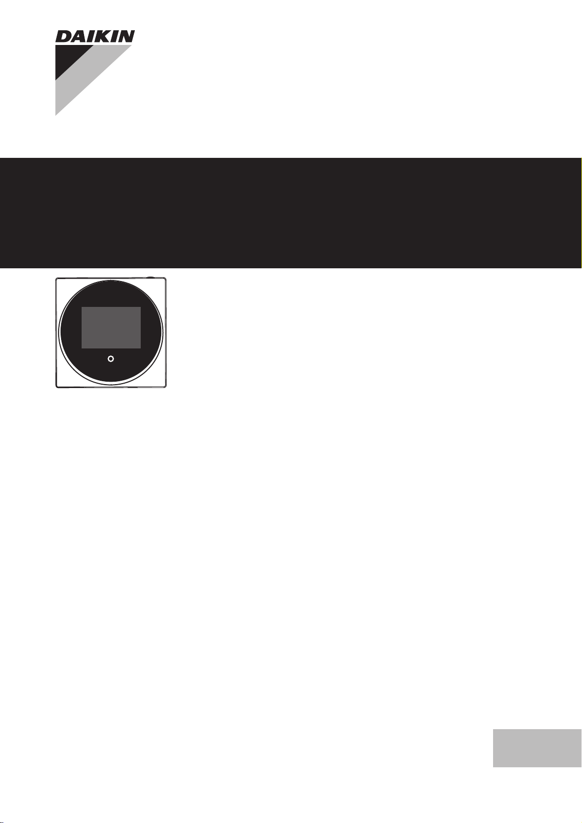
Wired remote controller
BRC1H81W
BRC1H81K
BRC1H81S
Installation and operation manual
Wired remote controller
English
Page 2
Table of Contents
Table of Contents
1 General safety precautions 2
1.1 For the user ............................................................................... 2
1.2 For the installer.......................................................................... 2
2 About this document 3
For the user 3
3 Buttons 3
4 Home screens 3
5 Status icons 4
6 Operation 4
6.1 Operation mode......................................................................... 4
6.1.1 To set the operation mode.......................................... 5
6.2 Setpoint ..................................................................................... 5
6.2.1 To set the setpoint ...................................................... 5
6.3 Airflow........................................................................................ 5
6.3.1 Airflow direction........................................................... 5
6.3.2 Airflow level................................................................. 5
6.4 Ventilation.................................................................................. 6
6.4.1 Ventilation mode ......................................................... 6
6.4.2 Ventilation rate ............................................................ 6
6.5 Advanced operation .................................................................. 6
6.5.1 To make a Bluetooth connection ................................ 6
7 Maintenance and service 6
7.1 Overview: Maintenance............................................................. 6
For the installer 6
8 About the box 6
8.1 To unpack the controller............................................................ 6
9 Preparation 7
9.1 Wiring requirements .................................................................. 7
10 Installation 7
10.1 Mounting the controller .............................................................. 7
10.1.1 To mount the controller ............................................... 7
10.2 Connecting the electrical wiring................................................. 7
10.2.1 To connect the electrical wiring................................... 7
10.3 Closing the controller................................................................. 8
10.3.1 To close the controller................................................. 8
11 Starting up the system 8
11.1 To designate a controller as slave............................................. 8
12 Maintenance 8
12.1 Maintenance safety precautions................................................ 8
12.2 To clean the controller ............................................................... 9
12.3 Time to clean filter indication ..................................................... 9
12.3.1 To remove the Time to clean filter indication .............. 9
1 General safety precautions
Please read these general safety precautions carefully before
installing air conditioning equipment, and be sure to install the
equipment correctly.
Failure to follow these instructions properly may result in property
damage or personal injury, which may be serious depending on the
circumstances.
1.1 For the user
INFORMATION
Also see the operation manual delivered with the outdoor
and indoor unit.
WARNING
Do NOT play with the unit or its remote controller.
Accidental operation by a child may result in impairment of
bodily functions and harm health.
WARNING
To prevent electric shocks or fire:
▪ Do NOT operate the controller with wet hands.
▪ Do NOT disassemble the controller and touch interior
parts. Contact your dealer.
▪ Do NOT modify or repair the controller. Contact your
dealer.
▪ Do NOT relocate or reinstall the controller by yourself.
Contact your dealer.
WARNING
Do NOT use flammable materials (e.g. hairspray or
insecticide) near the controller.
NOTICE
To clean the controller, do NOT use organic solvents, such
as paint thinner. Possible consequence: damage, electric
shock, or fire.
1.2 For the installer
▪ The precautions described in this document cover very important
topics, follow them carefully.
INFORMATION
This controller is an option and cannot be used standalone.
Also see the installation and operation manual of the
indoor and outdoor units.
NOTICE
Improper installation or attachment of equipment or
accessories could result in electric shock, short-circuit,
leaks, fire or other damage to the equipment. Only use
accessories, optional equipment and spare parts made or
approved by Daikin.
WARNING
All field wiring and components MUST be installed by a
licensed electrician and MUST comply with the applicable
legislation.
NOTICE
The remote controller MUST be mounted indoors.
NOTICE
When the controller is used as room thermostat, select an
installation location where the average temperature in the
room can be detected.
Do NOT install the controller in the following places:
▪ In places that are exposed to direct sunlight.
▪ In places that are near a heat source.
▪ In places that are affected by outside air or air draught due to e.g.
door opening/closing.
Installation and operation manual
2
BRC1H81W+K+S
Wired remote controller
4P513691-1 – 2017.10
Page 3

2 About this document
+
-
c b d
e
a
▪ In places where the display can easily get dirty.
▪ In places where there is NO easy access to the controls.
▪ In places with temperatures <–10°C and >50°C.
▪ In places where the relative humidity is >95%.
▪ In places where there is machinery that emits electromagnetic
waves. Electromagnetic waves may disturb the control system,
and cause malfunction of the equipment.
▪ In places where it may be exposed to water, or in generally moist
areas.
If you are NOT sure how to install or operate the unit, contact your
dealer.
After finishing installation:
▪ Conduct a trial operation to check for faults.
▪ Explain the user how to operate the controller.
▪ Ask the user to store the manual for future reference.
INFORMATION
Consult your dealer regarding the relocation and
reinstallation of the controller.
2 About this document
Target audience
Authorised installers + end users
Documentation set
This document is part of a documentation set. The complete set
consists of:
▪ Installation and operation manual:
▪ Installation instructions
▪ Basic operation instructions
▪ Format: Paper (in the box of the controller)
▪ Installer and user reference guide:
▪ Extended installation and operation information
▪ Format: Digital files on http://www.daikineurope.com/support-
and-manuals/product-information/
▪ Daikin Control Assistant in-app documentation:
▪ The controller only allows for basic settings and operation.
Advanced settings and operation are performed via the Daikin
Control Assistant app. For more information, see the app and
its in-app documentation.
▪ Format: App available from Google Play and the Apple Store
▪ Declaration of conformity:
▪ Hereby, Daikin Europe N.V. declares that the radio equipment
type BRC1H is in compliance with the Directive 2014/53/EU.
The original declaration of conformity is available from the
BRC1H product page http://www.daikin.eu/BRC1H.
▪ Format: Digital file from the product page
Latest revisions of the supplied documentation may be available on
the regional Daikin website or via your dealer.
The original documentation is written in English. All other languages
are translations.
Technical engineering data
▪ A subset of the latest technical data is available on the regional
Daikin website (publicly accessible).
▪ The full set of latest technical data is available on the Daikin
extranet (authentication required).
For the user
3 Buttons
a
ON/OFF
▪ When OFF, press to turn ON the system. As a result, the
status indicator (e) will turn ON too.
▪ When ON, press to turn OFF the system. As a result, the
status indicator (e) will turn OFF too.
b
ENTER/ACTIVATE /SET
▪ From the home screen, enter the main menu.
▪ From the main menu, enter one of the submenus.
▪ From their respective submenu, activate an operation/
ventilation mode.
▪ In one of the submenus, confirm a setting.
c
CYCLE/ADJUST
▪ Cycle left.
▪ Adjust a setting (default: decrease).
d
CYCLE/ADJUST
▪ Cycle right.
▪ Adjust a setting (default: increase).
INFORMATION
For a full description of the behaviour of the status
indicator, see the installer and user reference guide.
4 Home screens
Depending on installer configuration, your controller either has a
standard or a detailed home screen. In most cases, the standard
home screen gives you only the active operation mode, messages (if
BRC1H81W+K+S
Wired remote controller
4P513691-1 – 2017.10
Installation and operation manual
3
Page 4
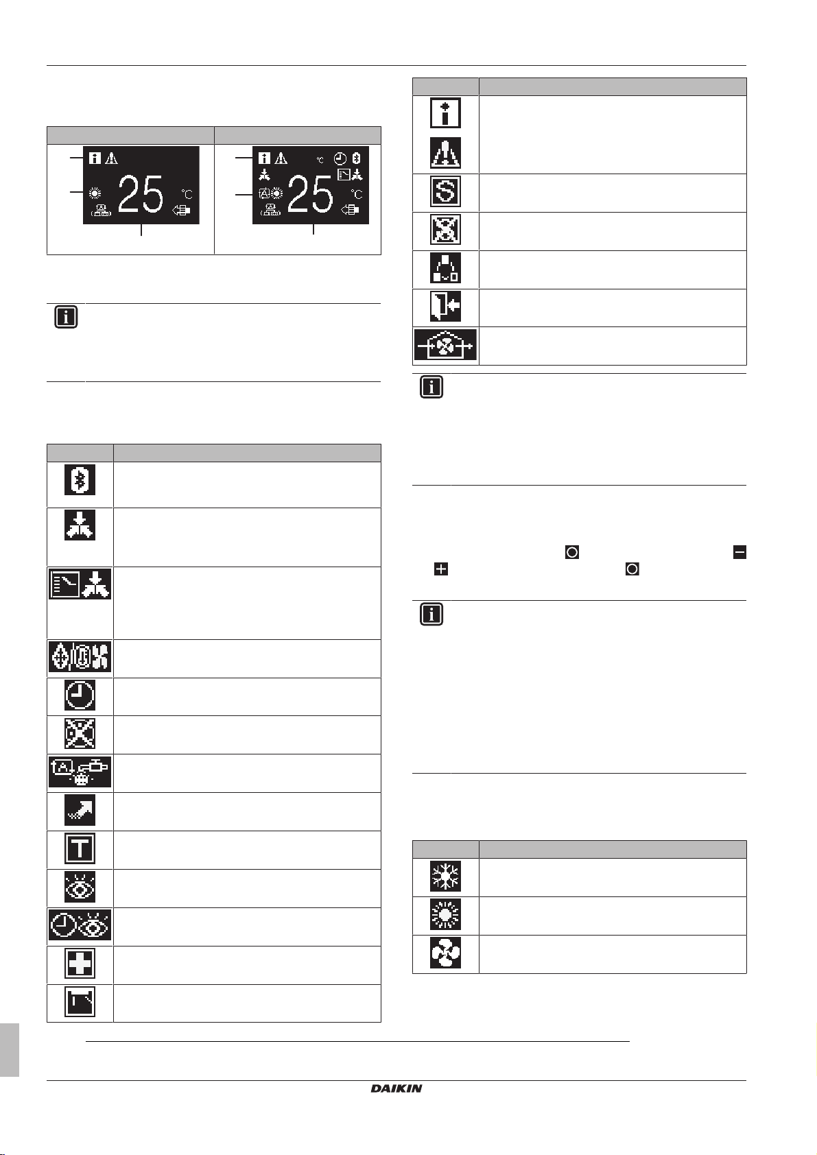
5 Status icons
a
b
c
19
a
b
c
any), and the setpoint temperature (in case of Cooling, Heating, or
Auto operation mode). The detailed home screen gives you all kinds
of information through status icons.
Standard Detailed
a Messages
b Active operation mode
c Setpoint temperature
INFORMATION
The controller is equipped with a power saving function
that causes the screen to go blank after a period of
inactivity. To make the screen light up again, press one of
the buttons.
5 Status icons
Icon Description
Bluetooth.1 Indicates that the controller is
communicating with a mobile device, for use with the
Daikin Control Assistant app.
Centralised control. Indicates that the system is
controlled by central control equipment (optional
accessory) and control of the system by this controller
is NOT possible.
Changeover under centralised control. Indicates
that the cooling/heating changeover is under
centralised control by another indoor unit, or by an
optional cool/ heat selector that is connected to the
outdoor unit.
Defrost/Hot start. Indicates that the defrost/hot start
mode is active.
Timer. Indicates that the schedule timer or OFF timer
is enabled.
Clock not set. Indicates that the Daikin Control
Assistant app clock is not set.
Self-cleaning filter. Indicates self-cleaning filter
operation.
Icon Description
Message. Indicates that the system has a message to
convey. Enter the menu to see the message.
Capacity restriction. Indicates that the system is
running with restricted capacity.
End of capacity restriction. Indicates that the
system is no longer running with restricted capacity.
Rotation. Indicates that Rotation mode is active.
Setback. Indicates that the indoor unit is operating
under setback control.
Ventilation. Indicates that the unit is ventilating the
space.
INFORMATION
▪ For information on the operation mode and ventilation
mode icons, see "6.1 Operation mode" on page 4
and "6.4.1Ventilation mode"on page6 respectively.
▪ Most icons are related to things set in the Daikin
Control Assistant app. For more information, see the
app, and the installer and user reference guide.
6 Operation
From the home screen, press
and to cycle through the menus. Press again to enter one of
the menus.
INFORMATION
▪ Depending on the type of indoor unit you are operating,
more or less menus may be available.
▪ In the main menu, the icon for each menu reflects the
current active setting or mode. When operating the
controller, the menu you navigate through can look
different from that represented in this manual.
▪ The controller only allows for basic operation of the
system. For advanced operation (schedules,
centralised control, …), see the Daikin Control
Assistant app.
to enter the main menu. Use
Quick Start. Indicates that Quick Start mode is active
(Sky Air only).
Test operation. Indicates that Test Operation mode
is active (Sky Air only).
Inspection. Indicates that the indoor or outdoor unit is
being inspected.
Periodic inspection. Indicates that the indoor or
outdoor unit is being inspected.
Backup. Indicates that in the system an indoor unit is
set as backup indoor unit.
Individual air direction. Indicates that the individual
air direction setting is enabled.
(1)
Installation and operation manual
4
The Bluetooth® word mark and logos are registered trademarks owned by the Bluetooth SIG, Inc. and use of such marks by
Daikin Europe N.V. is under license. Other trademarks and trade names are those of their respective owners.
6.1 Operation mode
The indoor unit can operate in various operation modes.
Icon Operation mode
Cooling. In this mode, cooling will be activated as
required by the setpoint or limit operation.
Heating. In this mode, heating will be activated as
required by the setpoint or setback operation.
Fan Only. In this mode, air circulates without heating
or cooling.
BRC1H81W+K+S
Wired remote controller
4P513691-1 – 2017.10
Page 5

Icon Operation mode
Dry. In this mode, the air humidity will be lowered with
a minimal temperature decrease.
The temperature and airflow level are controlled
automatically and cannot be controlled by the
controller.
Dry operation will not function if the room temperature
is too low.
Ventilation.In this mode, the space gets ventilated,
but not cooled or heated.
Air Clean. In this mode, the optional air cleaning unit
operates.
Ventilation + Air Clean. Combination of ventilation
and air clean operation.
Auto. In Auto mode, the indoor unit automatically
switches between heating and cooling mode, as
required by the setpoint.
INFORMATION
Depending on the indoor unit, more or less operation
modes are available.
6 Operation
Result: The indoor unit changes its temperature setpoint.
6.3 Airflow
6.3.1 Airflow direction
The airflow direction is the direction in which the indoor unit blows its
air.
INFORMATION
For more information, see the installer and user reference
guide.
To set the airflow direction
1 Navigate to the airflow direction menu.
6.1.1 To set the operation mode
1 Navigate to the operation mode menu.
2 Use and to select an operation mode.
3 Press to activate.
Result: The indoor unit changes its operation mode and the
controller returns to the homescreen.
6.2 Setpoint
The setpoint is the target temperature for the Cooling, Heating, and
Auto operation modes.
INFORMATION
The lower setpoint limit of the Cooling operation mode is
20°C, as per UAE Federal regulation UAE.S 5010-5:2016
clause 6, and UAE.S 5010-1:2016 clause 10.
6.2.1 To set the setpoint
Prerequisite: The active operation mode is either 'Cooling',
'Heating', or 'Auto'.
1 In the homescreen, use and to adjust the setpoint.
2 Use and to adjust the airflow direction.
3 Press to confirm.
Result: The indoor unit changes its airflow direction and the
controller returns to the homescreen.
6.3.2 Airflow level
The airflow level is the strength of the airflow coming out of the
indoor unit.
INFORMATION
For more information, see the installer and user reference
guide.
To set the airflow level
1 Navigate to the airflow level menu.
2 Use and to adjust the airflow level.
BRC1H81W+K+S
Wired remote controller
4P513691-1 – 2017.10
3 Press to confirm.
Result: The indoor unit changes its airflow level and the controller
returns to the homescreen.
Installation and operation manual
5
Page 6

7 Maintenance and service
6.4 Ventilation
INFORMATION
Ventilation settings can ONLY be made for heat reclaim
ventilation units.
6.4.1 Ventilation mode
The heat reclaim ventilation unit can operate in various operation
modes.
Icon Ventilation mode
Energy Reclaim Ventilation. The outdoor air is
supplied to the room after passing through a heat
exchanger.
Bypass. The outdoor air is supplied to the room
without passing through a heat exchanger.
Auto. To ventilate the room in the most efficient way,
the heat reclaim ventilation unit automatically
switches between "Bypass" and "Energy Reclaim
Ventilation" mode (based on internal calculations).
INFORMATION
Depending on the heat reclaim ventilation unit, more or
less ventilation modes are available.
To set the ventilation mode
1 Navigate to the ventilation mode menu.
2 Use and to adjust the ventilation rate.
3 Press to confirm.
Result: The heat reclaim ventilation unit changes its ventilation rate
and the controller returns to the homescreen.
6.5 Advanced operation
The controller only allows for basic operation. For advanced
operation, use the Daikin Control Assistant app. Before you can use
the app, you first have to make a Bluetooth connection between the
controller and the mobile device on which the app is installed.
6.5.1 To make a Bluetooth connection
Prerequisite: You have a mobile device on which the Daikin Control
Assistant app is installed and running.
Prerequisite: Your mobile device supports Bluetooth version 4.2.
1 Open the Daikin Control Assistant app and follow the
instructions from there.
2 Use and to select a ventilation mode.
3 Press to activate.
Result: The heat reclaim ventilation unit changes its operation mode
and the controller returns to the homescreen.
6.4.2 Ventilation rate
The ventilation rate is the strength of the ventilation operation.
To set the ventilation rate
1 Navigate to the ventilation rate menu.
For the installer
8 About the box
7 Maintenance and service
7.1 Overview: Maintenance
When the filter is dirty, the system is in error, or the indoor unit
needs to be maintained otherwise, consult your dealer.
To indicate this, you will be confronted by an error or maintenance
screen upon trying to enter the main menu.
Error screen (example) Maintenance screen (example)
8.1 To unpack the controller
1 Open the box.
2 Separate the accessories.
Installation and operation manual
6
BRC1H81W+K+S
Wired remote controller
4P513691-1 – 2017.10
Page 7

2×1×
a b
a Installation and operation manual
10 mm
L
a
b
c
b Wood screws + wall plugs (Ø4.0×30)
9 Preparation
9 Preparation
9.1 Wiring requirements
All wiring must comply with the following requirements:
Wire specification Value
Type Sheathed vinyl cord or cable (2
Section 0.75~1.25 mm
Maximum length 500 m
To prepare the wiring for installation:
1 Peel the sheath of the part of the cable that needs to pass
through the inside of the rear casing (L), according to the figure
and the table.
2 Keep a 10mm distance between the length of the 2 wires.
Wiring outlet L
Top ±150mm
Left ±120mm
Bottom ±100mm
wires)
2
10 Installation
a Wiring from the top
b Wiring from the left
c Wiring from the bottom
In case you are routing the wiring from the rear, you don't have to
remove anything.
10.1.1 To mount the controller
1 Take the screws and plugs from the accessory bag.
2 Mount the rear casing to a flat surface.
NOTICE
Be careful not to distort the rear casing by overtightening
the mounting screws.
10.2 Connecting the electrical wiring
10.1 Mounting the controller
Before you can mount the controller, you have to determine the
wiring routing, and accordingly, remove a piece of the controller's
rear casing.
The wiring can be routed from the top, the rear, the left, or the
bottom. Remove a piece of the rear casing according to the
illustration:
BRC1H81W+K+S
Wired remote controller
4P513691-1 – 2017.10
NOTICE
The wiring for connection is NOT included.
NOTICE
When wiring, run the wiring away from the power supply
wiring in order to avoid receiving electric noise (external
noise).
10.2.1 To connect the electrical wiring
Connect controller terminals P1/P2 to indoor unit terminals P1/P2.
Installation and operation manual
7
Page 8

11 Starting up the system
P1P2
P1P2
P1P2
P1P2
1
2
From the top
From the rear
From the left
10.3.1 To close the controller
1 Click the front of the controller into the rear casing.
11 Starting up the system
The controller gets its power from the indoor unit. It will start up as
soon as it is connected. For the controller to be operable, therefore
make sure the indoor unit is powered on.
Once the controller is powered, it will automatically start up. If it is
the first and only controller that is connected to the indoor unit, it will
automatically get designated as master controller. For a second
controller to get designated as slave controller, manual action is
required.
From the bottom
10.3 Closing the controller
CAUTION
Never touch the internal parts of the controller.
CAUTION
When closing the controller, be careful not to pinch the
wiring.
NOTICE
To prevent damage, make sure the front of the controller is
clicked into the rear casing securely.
11.1 To designate a controller as slave
Prerequisite: A master controller is already connected to the indoor
unit.
1 Connect a second controller.
Result: It will start up automatically.
2 Wait for a U5 or U8 error to appear on the screen.
3 When the U5 or U8 error appears, press
pressed until "2" appears on the screen.
Result: The controller is now designated as slave.
and keep it
12 Maintenance
12.1 Maintenance safety precautions
WARNING
Before carrying out any maintenance or repair activities,
stop system operation with the controller, and turn off the
power supply circuit breaker. Possible consequence:
electric shock or injury.
NOTICE
To clean the controller, do NOT use organic solvents, such
as paint thinner. Possible consequence: damage, electric
shock, or fire.
WARNING
Do not wash the remote controller. Possible
consequence: electric leakage, electric shock, or fire.
Installation and operation manual
8
BRC1H81W+K+S
Wired remote controller
4P513691-1 – 2017.10
Page 9

12.2 To clean the controller
1 Wipe the screen and other surface parts of the controller with a
dry cloth.
INFORMATION
If the dirt on the surface cannot be removed, soak the cloth
in neutral detergent diluted with water, squeeze the cloth
tightly, and clean the surface. Afterwards, wipe dry with a
dry cloth.
12.3 Time to clean filter indication
When the indoor unit filter is dirty and needs to be cleaned, the
controller will indicate this by displaying in the top right corner of
the home screen, and confronting you with the 'Time to clean filter'
screen as soon as you try to enter the main menu from the home
screen.
12.3.1 To remove the Time to clean filter indication
Prerequisite: On trying to enter the main menu from the home
screen, you are confronted with the 'Time to clean filter' screen.
12 Maintenance
1 Clean the filter.
2 Press to remove the 'Time to clean filter' indication.
BRC1H81W+K+S
Wired remote controller
4P513691-1 – 2017.10
Installation and operation manual
9
Page 10

Page 11

Page 12

4P513691-1 2017.10
Copyright 2017 Daikin
 Loading...