


TO INDEX
INTRODUCTION
INTRODUCTION
HOW TO USE THIS MANUAL
GENERAL INFORMATION |
IN-1 |
|
IN |
||
VEHICLE IDENTIFICATION NUMBER, ENGINE SERIAL NUMBER |
|
|
AND TRANSMISSION SERIAL NUMBER |
|
|
LOCATION. . . . . . . . . . . . . . . . . . . . . . . . . . . . . . . . . . . . . . . . . . . . . . . . . . |
IN-4 |
|
VEHICLE OPERATION AND PRECAUTION |
|
|
PRECAUTIONS . . . . . . . . . . . . . . . . . . . . . . . . . . . . . . . . . . . . . . . . . . . . . . |
IN-5 |
|
SUPPORT POSITIONS FOR JACK, RIGID RACK AND LIFT . . . . . . . . . . |
IN-17 |
|
HOW TO TROUBLESHOOT ECU CONTROLLED SYSTEMS |
|
|
NEW DIAGNOSTIC SYSTEM . . . . . . . . . . . . . . . . . . . . . . . . . . . . . . . . . . . |
IN-24 |
|
DESCRIPTION OF BASIC DIAGNOSTIC PROCEDURES . . . . . . . . . . . . . |
IN-26 |
|
CUSTOMER PROBLEM ANALYSIS . . . . . . . . . . . . . . . . . . . . . . . . . . . . . . |
IN-28 |
|
CONFIRMING SYMPTOMS AND CHECKING DIAGNOSTIC TROUBLE |
|
|
CODES . . . . . . . . . . . . . . . . . . . . . . . . . . . . . . . . . . . . . . . . . . . . . . . . . . |
IN-30 |
|
REPRODUCTION METHOD OF PROBLEM SYMPTOM . . . . . . . . . . . . . . |
IN-33 |
|
DIAGNOSTIC TROUBLE CODE CHART . . . . . . . . . . . . . . . . . . . . . . . . . . |
IN-34 |
|
PROBLEM SYMPTOMS TABLE . . . . . . . . . . . . . . . . . . . . . . . . . . . . . . . . . |
IN-35 |
|
DTC SYSTEM-SPECIFIC INSPECTION PROCEDURE . . . . . . . . . . . . . . . |
IN-36 |
|
ELECTRONIC CIRCUIT INSPECTION PROCEDURE . . . . . . . . . . . . . . . . |
IN-38 |
|
TERMS |
|
|
ABBREVIATIONS . . . . . . . . . . . . . . . . . . . . . . . . . . . . . . . . . . . . . . . . . . . . |
IN-44 |
|

IN–1
INTRODUCTION - HOW TO USE THIS MANUAL
HOWINTRODUCTION TO USE THIS MANUAL
IN
GENERAL INFORMATION
1.GENERAL DESCRIPTION
(a)Repair work can be divided into three processes: (1) diagnosis;
(2)installation, replacement, disassembly / reassembly and checking / adjusting; and (3) final inspection.
(b)This manual describes processes (1) diagnosis; and (2) installation, replacement, disassembly / reassembly and checking / adjustment. Procedure (3) final inspection is omitted.
(c)The following procedures are omitted from this manual. However, these procedures must be performed.
(1)The use of a jack or lift to perform operations.
(2)The washing and cleaning of removed parts, as needed.
(3)Visual checks.
2.PREPARATION
(a)To prepare you before performing work, a list of Special Service Tools (SST), service tools, recommendations, as well as lubricants and other items are in the PREPARATION section of this manual. However, equipment that is considered to be readily available in a repair facility, such as tool stands, jacks, and rigid racks, is omitted.
(b)Tools or devices other than Special Service Tools (SST) that are listed in the PREPARATION section of this manual are merely guides. They are not meant to designate specific suppliers, product names or part numbers.
3.WORK PROCEDURE
(a)A component illustration is placed under each section or title where necessary.

IN–2
INTRODUCTION - HOW TO USE THIS MANUAL
(b)Non-reusable parts, lubricant application areas, precoated bolts and tightening torque are noted in the component illustrations.
Example:
IN
 REAR AXLE SHAFT
OIL SEAL LH ADJUSTING LOCK CAP
REAR AXLE SHAFT
BEARING LH
REAR DISC BRAKE
 COTTER PIN
REAR AXLE CARRIER LH
REAR AXLE SHAFT LH
 REAR AXLE SHAFT
SNAP RING LH
 REAR AXLE SHAFT OIL SEAL LH
|
|
|
|
PARKING |
BRAKE FLUID |
ASSEMBLY |
|
|
|
NON-REUSEABLE |
PART |
||||
|
|
|
|
|
|
||
|
|
|
|
|
|
||
|
|
MP GREASE |
|
|
|
TIGHTENING TORQUE |
|
|
|
||||||
|
|
|
|
|
|
|
|
|
|
|
|
|
|
|
|
(c)Tightening torque, lubricant application areas and non-reusable parts are noted in the procedures.
NOTICE:
In some cases, the information listed above can only be explained by using an illustration. In these cases, torque, lubrication type and other information are described in the illustration.
(d)Only items with key points are described in the text. What to do and other details are explained using illustrations next to the text. Both the text and illustrations are accompanied by specified values and notices.
(e)Illustrations of similar vehicle models are sometimes used. In these cases, minor details may be different from the actual vehicle under repair.
Example: |
Operation |
|
|
||
|
17. CRANKSHAFT DAMPER INSTALLATION |
|
|
(1) Using the SST, hold the crankshaft damper and |
|
SST |
tighten the bolt. |
|
SST 09278-87201 |
||
|
||
|
Standard |
|
A137588 |
Explanation: A detailed explanation of the operation method |

IN–3
INTRODUCTION - HOW TO USE THIS MANUAL
|
|
|
4. |
SERVICE SPECIFICATIONS |
|
|
|
|
(a) SPECIFICATIONS and LIMITS are presented in boldface text |
|
|
|
|
throughout the manual. |
|
|
|
5. |
TERM DEFINITIONS |
|
|
|
|
|
|
|
Standard |
Refers to a range of acceptable values during checking and adjusting. |
|
|
|
|
|
|
IN |
|
Maximum limit |
Refers to minimum and maximum values that are not to be exceeded during checking and adjusting. |
|
|
|
|
||
|
|
In some cases, the method used to determine whether or not a measurement falls within the specified values is difficult. In |
||
|
|
|
||
|
|
Reference value |
these cases, if there is no danger that an actual malfunction will occur, reference values may be provided to help you make |
|
|
|
|
simpler measurements. |
|
|
|
|
|
|
|
|
CAUTION |
Indicates the possibility of injury to you or other people. Ignoring CAUTIONS may lead to accident or injury. |
|
|
|
|
|
|
|
|
NOTICE |
Indicates items that require special attention because of the possibility of damage to the vehicle and its components. This |
|
|
|
includes essential procedures as well as actions that should not be performed. |
||
|
|
|
||
|
|
|
|
|
|
|
HINT |
Provides additional information to help you perform repairs. |
|
|
|
|
|
|
|
|
|
6. |
INTERNATIONAL SYSTEM OF UNITS |
|
|
|
|
(a) The units used in this manual comply with the International |
System of Units (SI) standard. Units from the metric system are also provided.
(Example)
Torque: 28 N*m (286 kgf*cm)
Table of International System of Units Conversions
Item |
International System of Units |
Former Units |
Conversion Factor into |
|
International System of Units |
||||
|
|
|
||
Acceleration |
m/s2 |
G |
9.80665 |
|
Torque, Moment |
N*m |
kgf*cm |
0.0980665 |
|
|
|
|
|
|
Force |
N |
kgf |
9.80665 |
|
|
|
|
|
|
Pressure |
MPa |
kgf/cm2 |
0.0980665 |
|
kPa |
mmHg |
0.133322 |
||
|
||||
|
|
|
|
|
Power, Power Efficiency |
kW |
PS |
0.735499 |
|
|
|
|
||
W |
kcal/h |
1.16279 |
||
|
||||
|
|
|
|
|
Volume |
cm3 |
cc |
1 |
|
Spring Constant |
N/mm |
kgf/mm |
9.80665 |
|
|
|
|
|
International System of Units Prefixes
M (mega-) |
106 |
d (deci-) |
10-1=0.1 |
K (kilo-) |
103 |
c (centi-) |
10-2=0.01 |
H (hecto-) |
102 |
m (milli-) |
10-3=0.001 |
Da (deca-) |
101 |
µ (micro-) |
10-6=0.000001 |
INTRODUCTION - VEHICLE IDENTIFICATION NUMBER, ENGINE SERIAL NUMBER AND TRANSMISSION |
IN–4 |
SERIAL NUMBER |
|
VEHICLEINTRODUCTION IDENTIFICATION NUMBER, ENGINE SERIAL
NUMBER AND TRANSMISSION SERIAL NUMBER
A |
B |
D101216J01 |
LOCATION
IN
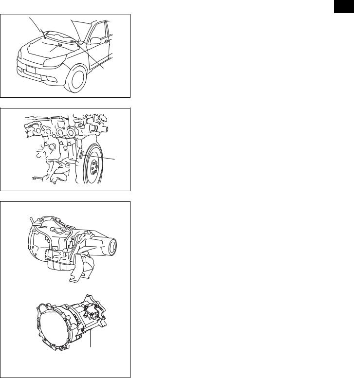
1.Vehicle Identification Number
(a)The vehicle identification number is stamped on the vehicle body (labeled A in the illustration) and on the certification label (labeled B in the illustration).
A:
Vehicle Identification Number B:
Certification Label
2. |
Engine Serial Number and Transmission Serial Number |
|
(a) The engine serial number is stamped on the cylinder block of |
|
the engine. |
|
A: |
|
3SZ, K3 |
A |
|
D101218J01 |
|
|
(b) The transmission serial number is stamped on the certification |
A/T |
label of the transmission case. |
|
A: |
A4Q-D1
B:
M5S
A
M/T
B
D101219J01

IN–5
INTRODUCTION – VEHICLE OPERATION AND PRECAUTION
VEHICLEINTRODUCTION OPERATION AND PRECAUTION
IN
PRECAUTIONS
1.FOR VEHICLES EQUIPPED WITH SRS AIRBAG AND SEAT BELT PRETENSIONER
(a)HANDLING AND OPERATING PRECAUTIONS
(1)Failure to carry out the service operations in the correct sequence could cause the airbag or pretensioner to unexpectedly deploy during servicing and lead to serious life-threatening injury. Furthermore, if a mistake is made when servicing, it is possible that the airbag or pretension may fail to operate properly. Service operations (including checking and adjusting) should be carried out in the correct sequence as stated in this manual.
(b)DISCONNECTING POWER SOURCE
(1)Always check the Diagnostic Trouble Codes (DTCs) before performing work. Before beginning work, wait at least 90 seconds after the engine switch is turned OFF and after the cable is disconnected from the negative (-) battery terminal.
CAUTION:
The airbag and pretensioner are equipped with a backup power source. If work is started within 90 seconds after turning the engine switch OFF and disconnecting the cable from the negative (-) battery terminal, the airbag or pretensioner may deploy.
(c)GENERAL PRECAUTIONS
(1)When performing an electrical check, use an electrical tester. However, never measure the resistance of the airbag squib.
CAUTION:
This may cause the airbag or pretensioner to inflate, which could cause serious injury.
(2)Information labels are attached to the SRS components. Follow the instructions on the labels.
(3)Never disassemble an SRS airbag.
(4)Replace any dropped, cracked, dented, broken or otherwise defective SRS components with new ones.
(5)Never use airbag or pretensioner parts from another vehicle. When replacing parts, use new parts.
(6)Do not directly expose any of the SRS components to hot air or flames.
(7)After a collision, perform a DTC check, even if the the airbag or pretensioner have not deployed.
(8)Lubricants, oil, water, or detergents of any kind should not be applied to any of the SRS components. If any of the SRS components come into contact with liquid, quickly wipe them off with a dry cloth.
(9)Store the SRS components in an area where the ambient temperature is below 93°C [80°C for the pretensioner], the humidity is not high and there is no electrical noise.

IN–6
INTRODUCTION – VEHICLE OPERATION AND PRECAUTION
(d)AIRBAG AND PRETENSIONER DISPOSAL PRECAUTIONS (BEFORE DEPLOYMENT)
(1)Never dispose of an airbag or pretensioner that has not deployed. (Be sure to deploy airbags with SSTs before disposal.)
(2)Airbags and pretensioners should be deployed in a flat area
in the open air, where safety can be ensured. In addition, IN avoid deploying air bags and pretensioners in residential areas.
(3)Because the sound an airbag or pretensioner makes when it is deployed is rather loud, give prior notice of deployment to those around you.
(4)When deploying the airbag or pretensioner, use the SST and stand at least 5 m away from the airbag or pretensioner.
(5)Because static electricity may cause the airbag or pretensioner to deploy, take prior measures to avoid static electricity.
(6)When deploying the airbag, be careful that the airbag deployment side is not facing downward.
CAUTION:
Deployment of the airbag with the airbag deployment side facing downward may lead to serious, lifethreatening injury.
(e)AIRBAG AND PRETENSIONER DISPOSAL PRECAUTIONS (AFTER DEPLOYMENT)
(1)Because the temperature of the airbag or pretensioner can reach several hundred degrees after deployment, you should not handle it for at least 30 minutes after deployment.
(2)Do not apply water, etc. to a steering pad with a deployed airbag or pretensioner.
(3)Use gloves and protective glasses when handling an airbag or pretensioner that has been deployed.
(4)Place an airbag or pretensioner that has been deployed in a clean, sturdy bag. Tie the opening of the bag tightly and dispose of the bag.
(5)Always wash your hands with water after completing work.
(f)PRECAUTIONS FOR AIRBAG STORAGE
(1)When removing the airbag, always store it with the deployment side facing upward. Do so even when removing the airbag only temporarily to perform work.
CAUTION:
Operating the airbag, for any reason, with the deployment side facing downward may lead to serious, life-threatening injury.
(2)When storing airbags, do not place anything on top of them. Also, do not stack airbags on top of each other.
(g)PRECAUTIONS FOR WIRE HARNESSES AND CONNECTORS
(1)With the exception of parts in the engine compartment that are not visible, airbag connectors are yellow. Be careful when handling these connectors.

IN–7
IN
INTRODUCTION – VEHICLE OPERATION AND PRECAUTION
(h)PROCEDURE FOR VEHICLES SUBJECTED TO IMPACT IN A COLLISION
(1)When using electric welders on the vehicle, disconnect the airbags and pretensioners before performing work.
(2)If any kind of impact is likely to occur, remove the center airbag sensor assembly, front airbag sensor, side airbag sensor assembly, airbag sensor rear, and seat position airbag sensor before beginning work.
(3)Do not expose the center airbag sensor assembly, front airbag sensor, side airbag sensor assembly, airbag sensor rear, or seat position airbag sensor to high temperature
(4)Because the temperature of some airbags or pretensioners can reach several hundred degrees after deployment, make sure that the surrounding wire harness and connectors are not damaged or melted.
2.BASIC REPAIR HINTS
(a) |
General |
|
5 |
1 |
|
|
3 |
|
2 |
6 |
4 |
|
|
|
D101220J01 |
1 |
Attire |
• Always wear a clean uniform. |
|
• Hat and safety shoes must be worn. |
|||
|
|
||
|
|
|
|
2 |
Vehicle protection |
• Lay down a grille cover, fender cover, seat cover and floor mat before performing work. |
|
|
|
|
|
|
|
• Use wheel chocks to secure the vehicle. |
|
|
|
• When working with 2 or more persons, be sure to check for the safety of one another. |
|
|
|
• When working with the engine running, make sure that there is adequate ventilation. |
|
3 |
Safe operation |
• When working on parts that get hot, or on high pressure, rotating, moving, or vibrating |
|
parts, take extra care not to burn or injure yourself. |
|||
|
|
||
|
|
• When jacking up the vehicle, support the vehicle using a rigid rack at the specified |
|
|
|
location. |
|
|
|
• When lifting up the vehicle, use appropriate safety equipment. |
|
|
|
|
|
INTRODUCTION – VEHICLE OPERATION AND PRECAUTION |
IN–8 |
|
|||
|
|
|
|
|
||
|
|
|
|
|
|
|
4 |
Preparation of tools and |
• Before performing work, prepare a tool stand, SST, gauge, oil and |
parts for |
|
|
|
measurement gauges |
replacement. |
|
|
|
|
|
|
|
|
|
|
||
|
|
|
|
|
||
|
|
• Diagnose with a thorough understanding of proper procedures and of the reported |
|
|
|
|
|
|
problem. |
|
|
|
|
|
Removal and installation, |
• Before removing parts, check the general condition of the assembly. Also, check for |
|
|
||
|
deformation and damage. |
|
|
|
|
|
5 |
disassembly and assembly |
|
|
|
|
|
• When the assembly is complicated, take notes and add matchmarks to ensure that |
|
|
IN |
|||
|
operations |
|
||||
|
parts can be replaced and reinstalled correctly. |
|
|
|
||
|
|
|
|
|
||
|
|
• Clean and wash the removed parts if necessary and assemble them after a thorough |
|
|
||
|
|
check. |
|
|
|
|
|
|
|
|
|
||
|
|
• Keep removed parts in sequence to avoid mixing them up with the new parts or |
|
|
|
|
|
|
contaminating the new parts. |
|
|
|
|
6 |
Removed parts |
• For non-reusable parts such as gaskets, O-rings, and self-locking nuts, replace them |
|
|
||
|
|
with new parts as instructed in this manual. |
|
|
|
|
|
|
• Retain the removed parts in a box and present them to the customer. |
|
|
|
|
|
|
|
|
|
|
|
(b)GASKETS
(1)Because it is not possible to reuse gaskets, always replace it with a new one.
(2)When necessary, use a sealer on gaskets to prevent leaks.
(c)BOLTS, NUTS AND SCREWS
(1)Check the tightening torque on bolts, nuts and screws. Always use a torque wrench.
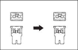
(d)REPLACE FUSES
(1)When replacing fuses, use fuses of the correct amperage rating. When the use of fuses with different ratings is
BE01367J01

IN–9
INTRODUCTION – VEHICLE OPERATION AND PRECAUTION
unavoidable, use fuses with a lower rating than the specified amperage.
IN
Diagram |
Symbol |
Part Name |
Abbreviation |
|
|
Fuse |
Fuse |
|
|
Medium Current Fuse |
M Fuse |
|
|
High Current Fuse |
H Fuse |
|
|
Fusible Link |
FL |
|
|
|
|
|
|
|
|
|
|
|
|
Circuit Breaker |
CB |
|
|
|
|
|
|
|
|
|
|
|
|
||
|
|
|
|
|
|
|
|
|
|
|
|
||
|
|
|
|
|
|
|
|
|
|
|
|
|
|
|
|
|
|
|
|
|
|
|
|
|
|
|
|
|
|
|
|
|
|
|
|
|
|
|
|
Fusible Link Assembly |
FL |
|
|
|
|
|
|
|
|
|
|
|
|
||
|
|
|
|
|
|
|
|
|
|
|
|
|
|
|
|
|
|
|
|
|
|
|
|
|
|
|
|
D100151J02
(e)Clip
(1)When separating and disengaging the clip and claw positions, apply protective tape to prevent damaging the vehicle.
(2)The removal and installation methods of typical clips used for vehicle body parts are shown in the table.
HINT:
•If clips are damaged during installation, always replace them with new clips.
IN–10
INTRODUCTION – VEHICLE OPERATION AND PRECAUTION
•The pmark in the illustration refers to clips, and the {mark refers to claws.
IN

IN–11
INTRODUCTION – VEHICLE OPERATION AND PRECAUTION
Shapes (Examples) |
Removal And Installation |
|
Clip |
Clip Remover |
|
IN |
|
Pliers |
Clip |
|
|
|
|
Screwdriver |
|
Protective Tape |
|
Claw |
|
|
|
|
Roof Molding Remover |
Clip |
Removal |
Installation |
|
|
|
|
Removal |
Installation |
Clip |
|
|
|
|
D100768J01 |

IN–12
INTRODUCTION – VEHICLE OPERATION AND PRECAUTION
(f)FRAMING ADJUSTMENTS
(1)When centering bolts are used on hinges of hoods, doors
|
or luggage compartment doors, etc. perform framing |
Centering Bolt |
|
|
adjustments before replacing the supplied bolts. |
(g)JACKING UP, LOWERING AND SUPPORTING VEHICLE
(1)Always observe precautions when jacking up, lowering and supporting the vehicle. (See page IN-17 for support IN positions for jacks, the rigid rack and lifts.)
D032152J01
(h)REMOVAL AND INSTALLATION OF VACUUM HOSES
(1)To disconnect a vacuum hose, pull from the end of the hose.
D025063J01
(2)When disconnecting vacuum hoses, use tags to identify where they should be reconnected.
(3)When using a vacuum gauge, do not connect a hose that is too large. If the hose is a little small, use an adapter for adjustment. If a hose has been stretched, it may leak air.
|
D025064J01 |
|
|
|
|
|
|
|
|
(i) |
TORQUE |
WHEN |
USING |
TORQUE |
WRENCH |
WITH |
|
L1 |
L2 |
EXTENSION TOOL |
|
|
|
|
||
(1) |
If an extension |
tool or SST is combined with a torque |
||||||
|
|
|
wrench, do not tighten to the torque specified in this |
|||||
|
|
|
manual. Doing so will result in excessive actual torque. |
|||||
|
|
(2) |
In this |
manual, |
only standard tightening torque is listed. |
|||
|
|
|
Use the formula below to calculate special torque values for |
|||||
|
|
|
situations where an SST or an extension tool is combined |
|||||
|
|
|
with the torque wrench. |
|
|
|
||
L1 |
L2 |
(3) Calculation Formula T' = T × L2/(L1 + L2) |
|
|||||
|
|
|
T' |
|
|
Reading of torque wrench (N*m |
||
|
|
|
|
|
[kgf*cm]) |
|
||
|
|
|
|
|
|
|
||
|
|
|
T |
|
|
Reading of tightening torque |
|
|
|
|
|
|
|
(N*m[kgf*cm]) |
|
||
|
|
|
|
|
|
|
||
|
D100769J01 |
|
L1 |
|
Length of SST or extension tool (cm) |
|||
|
|
L2 |
|
|
Length of torque wrench (cm) |
|||
|
|
|
|
|
||||
IN–13
INTRODUCTION – VEHICLE OPERATION AND PRECAUTION
Loosen
IN
D001555J01
D001556J01
3.ELECTRICAL CONTROL
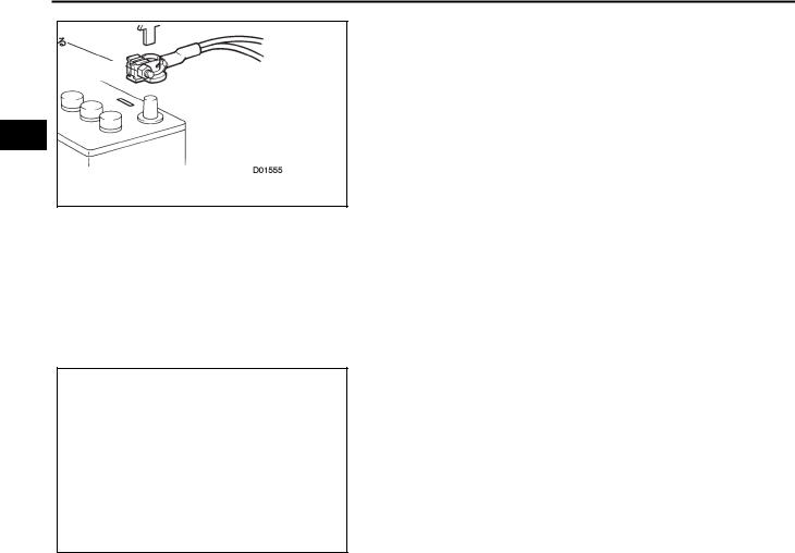
(a)REMOVAL AND INSTALLATION OF BATTERY TERMINAL
(1)Before performing work on electrical systems, first disconnect the cable from the negative (-) battery terminal to prevent component and wire damage caused by accidental short circuits.
(2)When disconnecting and reconnecting the battery cable, turn the engine switch OFF and turn the headlight switch OFF. Also, loosen the terminal nut completely. Perform these operations without bending the terminals.
(3)Clock settings, DTCs and other data are erased when the negative (-) battery terminal is disconnected. Therefore, write down any necessary data before disconnecting the negative (-) battery terminal.
(4)After disconnecting the battery terminals, settings may be erased. Therefore, make sure to perform the necessary set-up operations after reconnecting the terminals. (See page SS-10 for details)
(b)HANDLING OF ELECTRONIC PARTS
(1)Do not open the cover or case of the ECU. (If the IC terminals are touched, the IC may be rendered inoperative by static electricity.)
(2)Avoid any impact to electronic components such as sensors or relays. If they are dropped, they should be replaced.
(3)Do not expose any electronic parts to high temperature or humidity.
(4)When cleaning the engine with steam, protect the electronic components, air filter and emission-related components from water.
(5)Do not touch the connector terminals in order to prevent deformation or malfunctions due to static electricity.
(6)Do not use an impact wrench to remove or install a temperature switch or temperature sensor.
4.REMOVAL AND INSTALLATION OF FUEL CONTROL PARTS
(a)PLACE FOR REMOVING AND INSTALLING FUEL CONTROL PARTS
(1)Work in a location with good air ventilation that does not have welders, grinders, drills, electric motors, stoves, or any other sources of sparks or flames.
(2)Never work in a pit or near a pit as vaporized fuel can collect in those places.
(b)REMOVAL AND INSTALLATION OF FUEL CONTROL PARTS
(1)Prepare a fire extinguisher before starting work.
(2)To prevent static electricity, install a ground wire to the fuel changer, vehicle and fuel tank. Also, wet the ground moderately so that the the area around your feet is not slippery.
(3)Avoid using electric pumps, working lights or other electrical equipment that can cause sparks or high temperatures.
(4)Avoid using iron hammers as they may create sparks during work.
(5)Dispose of fuel-contaminated cloth separately.

IN–14
INTRODUCTION – VEHICLE OPERATION AND PRECAUTION
5.REMOVAL AND INSTALLATION OF ENGINE INTAKE PARTS
(a)If any metal particles enter inlet system parts, this may have a harmful effect on the engine.
(b)When removing and installing inlet system parts, cover the openings of the removed inlet system parts. Also, cover the engine side openings. Use gummed tape or a clean rag.
(c)When installing the inlet system parts, confirm that no metal IN particles have entered the installed parts.
D001563J01
Pull The Tabs To Open The Clamp
Clamp Mark
D001559J01
Do Not Illuminate More Than 3 Minutes |
D101221J01 |
6.HANDLING OF HOSE CLAMPS
(a)Before removing a hose, confirm the hose plug depth and the clamp position so that the hose can be reinstalled in the same position.
(b)Replace any deformed or dented clamps with new ones.
(c)When reusing a hose, attach the clamp by aligning it with the track portion of the hose.
(d)After attaching a spring type clamp, apply force and push in the direction of the arrows.
7.FOR VEHICLES EQUIPPED WITH MOBILE COMMUNICATION SYSTEMS
(a)Install the antenna as far away from the computer sensors of the vehicle electronic systems as possible.
(b)Install the antenna feeder at least 20 cm (7.87 in.) away from the computer sensors of the vehicle electronic systems.
(c)Do not put the antenna feeder together with other wires. Keep the antenna feeder separate from other wiring as much as possible.
(d)Install the antenna securely, using the appropriate installation manual as a reference.
(e)Do not install a high-powered mobile communication system.
8.CHECKING AND ADJUSTING HEADLIGHTS
(a)When the discharge headlights are ON, never touch the high voltage socket.
(b)Do not use a cover when the headlights are ON for more than 3 minutes.
NOTICE:
•Observe the precautions on handling discharge headlights when checking and adjusting. (For precautions on the lighting system, see page LI-1.)
•Because the outer lens of the headlight is made of resin, it may melt if it is covered for extended periods of time.
9.TRACTION CONTROL (TRC) AND VEHICLE STABILITY CONTROL (VSC)
(a)PRECAUTIONS FOR USING 2-WHEEL DRUM TESTER
(1)When using a 2-wheel drum tester such as a speedometer tester, a combination tester for the speedometer and brake,

IN–15
IN
INTRODUCTION – VEHICLE OPERATION AND PRECAUTION
or a chassis dynamometer, turn the TRC or VSC system OFF before performing measurements.
CAUTION:
When using a drum tester, there is a danger that the vehicle may jump out of the tester if TRC and VSC system are not disabled.
NOTICE:
•To see if TRC or VSC operation is prohibited, check that the VSC OFF light on the combination meter is flashing and that the slip indicator light on the combination meter is illuminated.
•Secure the vehicle with a lock chain for safety.
HINT:
For the suppression method for the TRC and VSC system, see PRECAUTIONS WHEN USING DRUM TESTERS in the PRECAUTIONS section regarding the ABS system with electronic brake force distribution, as well as the TRC, VSC and BA systems.
(2)When inspection using the drum tester is completed, always turn the ignition switch to the OFF position. Also release the prohibition on TRC and VSC system.
CAUTION:
Never drive the vehicle in PROHIBIT OPERATION MODE.
(b)NOTICES OF OPERATIONS RELATED TO VSC
(1)Do not carry out unnecessary installation and removal as it might affect the adjustment of VSC related parts.
(2)When performing operations related to VSC, be sure to follow the instructions for work preparation in this manual and final confirmation of the VSC system.
10.PRECAUTIONS FOR CHECKING AND ADJUSTING FULL TIME FOUR WHEEL DRIVE VEHICLES
NOTICE:
It is not possible to use a tester that only has a biaxial load setting mechanism (kinds that only have 2-wheel motion absorption mechanisms, such as a 2-wheel chassis dynamometer or a combination tester for a chassis dynamometer, speedometer and brake tester).
(a)Speedometer Tester Measurements HINT:
• BFR-60 Type (Manufactured by Banzai)
• IFR-600 Type (Manufactured by Iyasaka)
NOTICE:
• When starting off rapidly, do not race the engine.
IN–16
INTRODUCTION – VEHICLE OPERATION AND PRECAUTION
D101274 |
(1)Drive the rear wheels onto the roller.
(2)Turn off the differential lock switch.
(3)Free the front wheels using a free roller.
(4)Secure the vehicle with a lock chain.
(5)Start the engine and, in the D position, gradually increase
the vehicle speed. Then perform measurements.
(6) After completing measurements, gradually decelerate using IN the brake and stop the engine.
11.MEASURING BRAKE TESTER NOTICE:
•Testers with a load setting mechanism cannot be used.
•High speed models of brake testers cannot be used.
(a)Turn off the differential lock switch.
(b)Drive the vehicle to be measured (front wheels or back wheels) onto the roller.
(c)Set the shift position to neutral.
(d)Run the roller tester and perform measurements.
12.TOWING FR VEHICLES
Prohibited |
Prohibited |
D101224 |
(a)Tow vehicles with the rear wheels or all 4 wheels raised. Furthermore, when towing with all 4 wheels on the ground, tow facing forward with a towing speed of less than 30 km/hour (19 mph). Do not tow the vehicle a distance greater than 80 km (approximately 50 miles).
NOTICE:
Towing at speeds or for distances that exceed these figures, or towing facing backwards will have a harmful effect on and may damage the transaxle.
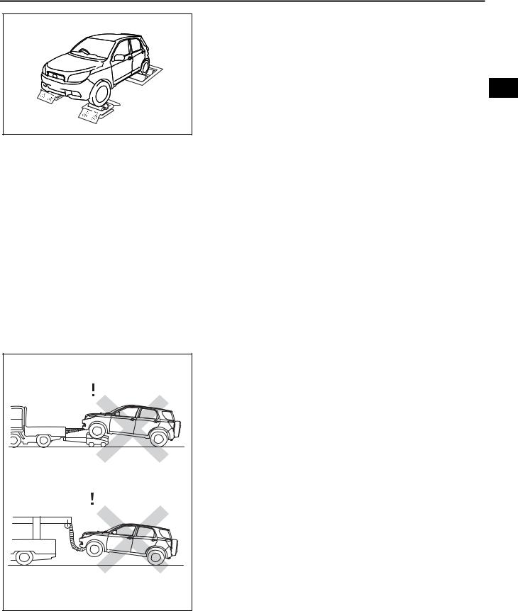
13.TOWING FULL TIME FOUR WHEEL DRIVE VEHICLES
(a)Tow vehicles with all 4 wheels on the ground or with all 4 wheels raised. Furthermore, when towing with all 4 wheels on the ground, tow facing forward with a towing speed of less than 30 km/hour (19 mph). Do not tow the vehicle a distance greater than 80 km (approximately 50 miles).
NOTICE:
Towing at speeds or for distances that exceed these figures, or towing facing backwards will have a adverse effect on and may damage the transmission.
(b)Do not tow with only the front or back wheels raised. Furthermore, if there is a malfunction in the running or driving system, only tow with all four wheels raised.
NOTICE:
Towing with only the front or only the back wheels raised may cause the vehicle to jump out of the wheel dolly.

IN–17
INTRODUCTION – VEHICLE OPERATION AND PRECAUTION
(c)Tow using one of the methods shown in the illustration.
Car Carrier |
Tow Truck (Raising All Four Wheels) |
Tow Truck (All Tires In |
|
|
|
Contact With The Road) |
|
IN |
|
Towing Speed |
Less Than 30 km/h |
|
Towing Distance |
Less Than 80 km |
|
|
|
Direction To Tow |
|
|
|
D101225 |
|
|
NOTICE: |
|
|
|
• If there is a malfunction in the chassis or drive line, use |
||
|
a carrier car. |
|
|
|
• Do not tow using a method not shown in the illustration. |
||
PARKING BRAKE AND SHIFT LEVER CONDITIONS WHEN TOWING |
Transmission |
||
Towing Method |
Parking brake |
||
Shift Lever Position |
|||
|
|
||
Carrier Car |
Brake is ON |
Either position is OK |
|
Tow truck (with 4 wheels) |
Brake is ON |
Either position is OK |
|
Tow truck (with 4 wheels on the ground) |
Brake is OFF |
Neutral |
|
14.FOR VEHICLES EQUIPPED WITH CATALYTIC CONVERTER
(a)If a large amount of unburned gasoline flows into the converter, it will cause damage to the catalytic converter. To avoid this, observe the following precautions.
(1)Use only unleaded gasoline.
(2)If a spark check of the spark plugs is required, stop the fuel jet and remove the injector connectors.
(3)When measuring the compression pressure of the engine, stop the fuel jet and remove the injector connectors.
(4)Do not run the engine when the fuel tank is nearly empty. This may cause the engine to misfire and put an extra load on the converter.
SUPPORT POSITIONS FOR JACK,
RIGID RACK AND LIFT
1.NOTICE ABOUT JACKING UP VEHICLE
(a)The vehicle must be almost completely unloaded before jacking up / lifting up the vehicle. Never jack up / lift up a heavily loaded vehicle.
(b)When removing heavy parts such as the engine or transmission, the center of gravity of the vehicle may shift. To stabilize the vehicle, place a balance weight in a location where it will not roll or shift, or use a mission jack to hold the jacking support.

IN–18
INTRODUCTION – VEHICLE OPERATION AND PRECAUTION
(c)When jacking up the vehicle, be sure to support the specified location with a jack, rigid rack, receiving block or other attachments.
(d)Do not jack up or lift up a vehicle that exceeds the ability of the jack or lift.
IN
IN–19
INTRODUCTION – VEHICLE OPERATION AND PRECAUTION
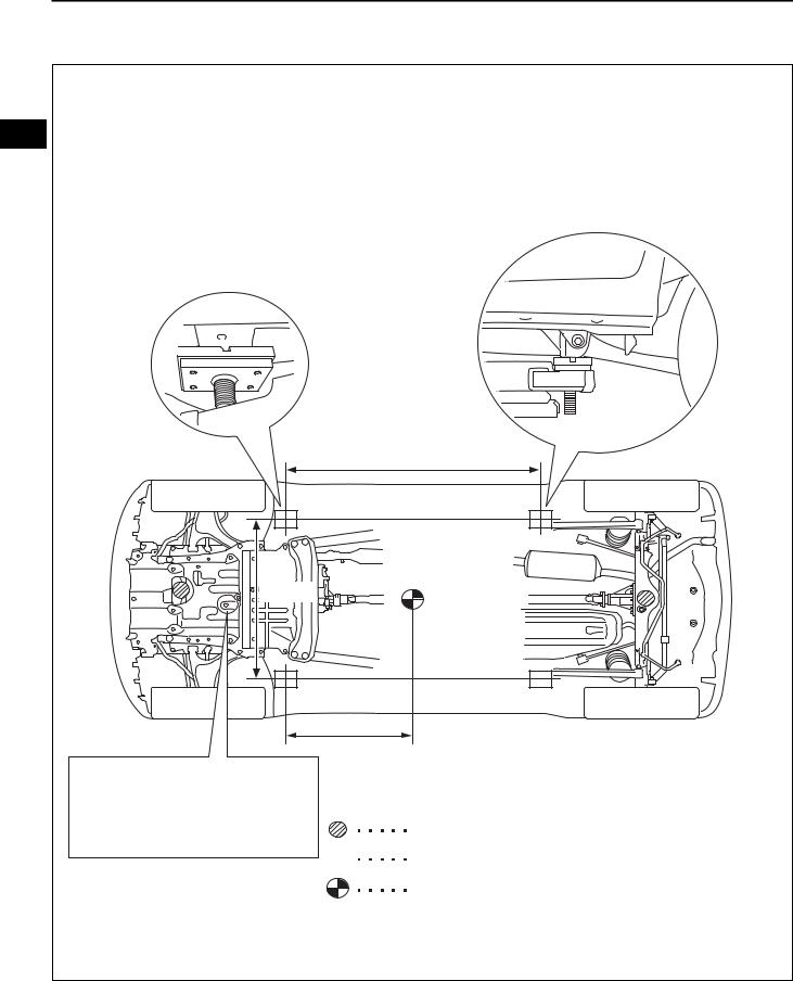
2.NOTICE ABOUT SUPPORT POSITIONS WHEN JACKING UP VEHICLE
IN
1500mm
1175mm
|
700mm |
|
Do not jack up the vehicle by the oil |
|
|
pan. |
|
|
(Caution) |
|
|
Position the jack carefully in order not |
|
Garage Jack Support Position |
to mistake the jacking position. |
|
|
|
|
|
|
|
Rigid Rack, Lift Up Support Position |
|
|
|
|
|
Vehicle Center Of Gravity |
|
|
(Approximate Center Of Gravity When Vehicle Is Empty ) |
D101222J01
3.PRECAUTIONS FOR USING JACKS AND RIGID RACKS
(a)Work on a level surface. Use wheel chocks at all times.
INTRODUCTION – VEHICLE OPERATION AND PRECAUTION |
IN–20 |
|
||
|
|
|||
Rubber Attachment |
(b) |
Rigid racks contain a rubber attachment like the one shown in |
|
|
|
the illustration. |
|
|
|
|
(c) |
The jack supports the specified location securely at the center |
|
|
|
|
of the jack plate . |
|
|
|
|
NOTICE: |
|
|
|
|
Because the shape of the oil pan makes it easy to mistake |
IN |
|
|
|
for the jack support location, take care not to use a garage |
||
|
|
jack. |
|
|
|
(d) |
The rigid rack supports the specified location securely. |
|
|
D101226J01 |
(e) |
When jacking up the front wheels, release the parking brake |
|
|
|
|
and make sure wheel chocks are behind the rear wheels. When |
|
|
|
|
jacking up the rear wheels, make sure wheel chocks are in front |
|
|
|
|
of the front wheels. |
|
|
|
(f) When jacking up only the front wheels or rear wheels of the |
|
||
|
|
vehicle, make sure wheel chocks are both in front of and behind |
|
|
|
|
the wheels of the vehicle that are on the ground. |
|
|
|
|
HINT: |
|
|
|
|
Do not perform any work on or leave unattended a vehicle that |
|
|
|
|
is supported solely by a jack. Rigid racks must be used to |
|
|
|
|
support the vehicle. |
|
|
|
(g) |
When lowering a vehicle that has been jacked up on only under |
|
|
|
|
its front wheels, release the parking brake and use wheel |
|
|
|
|
chocks only in front of the rear wheels. When lowering a vehicle |
|
|
|
|
that has been jacked up on only its rear wheels, use wheel |
|
|
|
|
chocks only in back of the front wheels. |
|
|
4. |
PRECAUTIONS FOR USING PLATE LIFT |
|
|
|
|
(a) |
Perform work safely, following the instructions in the lift manual. |
|
|
|
(b) |
Use a lift that can securely set the support position of the |
|
|
|
|
vehicle. |
|
|
|
(c) |
Use a receiving block and try not to hit the rocker moulding, etc. |
|
|
|
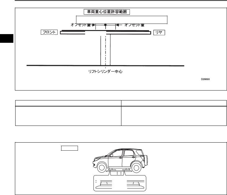
(d) |
Check that the vehicle's center of gravity is properly located |
|
|
|
|
over the lift cylinder. |
|
|
|
|
NOTICE: |
|
|
|
|
If the vehicle load is outside the lift's acceptable load |
|
|
|
|
range, there is a possibility that the vehicle will shake when |
|
|
|
|
raising and lowering it. |
|
|
|
|
HINT: |
|
|
|
|
If the acceptable vehicle load range is not clear, contact the |
|
|
|
|
maker of the lift. |
|
|
IN–21
INTRODUCTION – VEHICLE OPERATION AND PRECAUTION
IN
Acceptable Range For Vehicle Center Of Gravity
|
Offset Weight |
|
|
|
Offset Weight |
||||
|
|
|
|
|
Front |
|
|
|
Rear |
Lift Cylinder Center
D026693
(e)Always drive the vehicle onto the specified position.
Left and right set positions |
Drive the vehicle onto the center of the lift. |
Align the edges of the underside of the attachment with the rubber
Front and rear set position
edges of the plate cushion. (Part A, Part C)
Align the edges of the underside of the attachment with the front side of the rigid rack support position. (Part B)
(f)Lift up the vehicle so that the tires rise slightly and shake the vehicle to check that the vehicle is stabilized.
Plate Lift
B |
C |
A |
D101227
IN–22
INTRODUCTION – VEHICLE OPERATION AND PRECAUTION
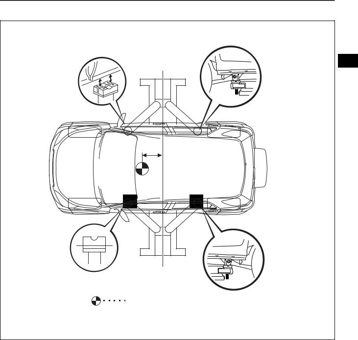
5.PRECAUTIONS FOR USING SWING ARM LIFT
IN |
L |
Vehicle Center Of Gravity (Vehicle Empty) |
D101228J01 |
(a)Perform work safely, following the instructions in the lift manual.
(b)Receiving stands use a rubber attachment like the one shown in the illustration.
(c)Position the vehicle so that the center of the lift and the center of gravity of the vehicle are as close as possible. (L is as short as possible.)
(d)Keep the vehicle level and adjust the height of the receiving stand so that it does not hit the rocker moulding. Securely align the rigid rack support position with the receiving stand groove.
(e)Always keep the swing arm locked when performing work.
(f)Lift up the vehicle so that the tires rise slightly and shake the vehicle to check that the vehicle is stabilized.
6.PRECAUTIONS WHEN USING 4 POST LIFT AND DRIVE-ON TYPE LIFT
(a)Perform work safely by following the lift manual.

IN–23
INTRODUCTION – VEHICLE OPERATION AND PRECAUTION
(b) Do not damage the tires or wheels with the free wheel beam.
(c) Use wheel chocks to secure the vehicle.
IN
IN–24
INTRODUCTION - HOW TO TROUBLESHOOT ECU CONTROLLED SYSTEMS
HOWINTRODUCTION TO TROUBLESHOOT ECU CONTROLLED SYSTEMS
DLC
SIL Diagnostic Communication (Communication Speed 10.4 kbps or 9.6 kpbs)
CAN Diagnostic Communication (Communication Speed 500 kbps)
ECU Communicating
DS-II
Diagnostic Tool DS-II
Each Diagnostic
Communication
Connection
D100834J03
NEW DIAGNOSTIC SYSTEM
1.DESCRIPTION
(a)The new diagnostic system is a new diagnostic system IN compatible with the vehicle's highly developed and sophisticated electronic system. The function of the malfunction diagnostic system can be utilized with the DS-II diagnostic tool.
2.FUNCTIONS OF DS-II DIAGNOSTIC TOOL
(a)The functions of the DS-II diagnostic tool, which is compatible with this new diagnostic system, are shown below.
Function |
|
Description |
|
|
Vehicle Diagnosis |
ALL diagnosis |
|
|
|
||
|
CAN bus diagnosis |
||
|
|
||
|
|
|
|
|
|
Diagnostic code freeze data |
|
|
|
|
|
|
|
ECU DATA LIST |
|
|
|
|
|
Diagnosis |
|
ACTIVE TEST |
|
|
|
||
System Diagnosis |
Mode change |
||
|
|||
|
|
||
|
Freeze data operation |
||
|
|
||
|
|
|
|
|
|
TEST MODE INSPECTION |
|
|
|
|
|
|
|
BASIC INSPECTION |
|
|
|
|
|
|
|
Specified operation / Control record |
|
|
|
|
|
OPERATION SUPPORT |
Required operation support functions when replacing ECU or actuator |
||
|
|
||
Stored Data |
Functions for outputting / Erasing stored data |
||
|
|
||
Measure |
Load voltmeter side and oscilloscope functions |
||
|
|
|
|
3. COMPUTERS AND SENSORS RELATED TO DIAGNOSTIC COMMUNICATION
|
|
|
Freeze Frame |
|
|
|
|
|
|
DTC Check |
Data |
|
|
DS-II and |
|
Computer |
DTC Check |
Computer Data |
Data Monitor |
|
|||
(Check Mode, |
ACTIVE TEST |
Communication |
|||||
Sensor Name |
Normal Mode) |
When a |
Save / Display |
||||
Test Mode) |
|
Line |
|||||
|
|
Malfunction |
|
|
|||
|
|
|
|
|
|
||
|
|
|
Occurs |
|
|
|
|
EFI ECU |
{ |
- |
{ |
{ |
{(*) |
CAN |
|
|
|
|
|
|
|
|
|
Automatic ECU |
{ |
- |
{ |
{ |
{(*) |
SIL |
|
|
|
|
|
|
|
|
|
ABS ECU |
{ |
{ |
{ |
{ |
{ |
SIL |
|
|
|
|
|
|
|
|
|
Airbag ECU |
{ |
- |
- |
- |
- |
SIL |
|
|
|
|
|
|
|
|
|
Immobilizer ECU |
{ |
- |
- |
{ |
- |
SIL |
|
|
|
|
|
|
|
|
*: Data monitor can be used simultaneously
IN–25 |
INTRODUCTION - HOW TO TROUBLESHOOT ECU CONTROLLED SYSTEMS |
||
|
|||
|
4. |
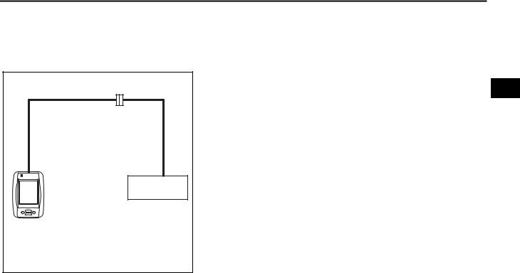
HOW TO USE DS-II DIAGNOSTIC TOOL |
|
|
|
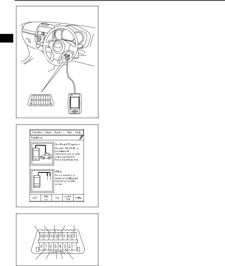
(a) |
CONNECT TO VEHICLE |
|
|
|
(1) Connect the DS-II to the DLC (data link connector No. 3) |
|
|
|
located in the area around the driver's foot. |
IN |
|
|
|
|
D101229J01 |
|
|
|
|
|
|
D101275 |
|
|
DLC |
|
|
BAT |
CANL ECU-T EFIT |
REV |
|
|
SIO |
CANH |
E E EPS-TS |
D101231J01 |
|
|
|
|
|
|
(b)HOW TO USE DS-II DIAGNOSTIC TOOL
(1)When the power switch of the diagnosis tool DS-II is turned ON, the menu screen will be displayed.
(2)Select the options you wish to perform. Then perform work, following the prompts on the screen.
5.DIAGNOSIS CONNECTOR
(a)With the adoption of the new diagnostic system, the functions are consolidated on the DLC (located in the lower portion of the driver instrument panel).
(b)DLC Terminals and Functions
Terminal Name |
Function |
|
BAT |
Battery power supply |
|
|
|
|
CANL |
Each computer and its diagnosis CAN |
|
communication LO |
||
|
||
|
|
|
ECU-T |
ECU-T check terminal |
|
|
|
|
ECU-T |
EFI-T check terminal |
|
|
|
|
REV |
Engine revolution signal |
|
|
|
|
SIO |
Each computer and diagnostic communication |
|
|
|
|
CANH |
Each computer and its diagnostic CANHI |
|
communication |
||
|
||
|
|

|
|
|
|
INTRODUCTION - HOW TO TROUBLESHOOT ECU CONTROLLED SYSTEMS |
IN–26 |
||||||||||||
|
|
|
|
|
|
|
|||||||||||
|
|
|
|
|
|
|
|
|
|
|
|
|
|
|
|
|
|
|
|
|
|
|
|
|
|
|
|
|
|
|
Terminal Name |
Function |
|
|
|
|
|
|
|
|
|
|
|
|
|
|
|
|
E |
Signal ground |
|
|
|
|
|
|
|
|
|
|
|
|
|
|
|
|
|
|
|
|
|
|
|
|
|
|
|
|
|
|
|
|
|
|
E |
Body ground |
|
|
|
|
|
|
|
|
|
|
|
|
|
|
|
|
|
|
|
|
|
|
|
|
|
|
|
|
|
|
|
|
|
|
EPS-TS |
EPS-TS check terminal |
|
|
|
|
|
|
|
|
|
|
|
|
|
|
|
|
|
|
|
|
|
|
|
|
|
|
|
|
|
|
|
|
|
|
6. HOW TO PROCEED WHEN ERRORS OCCUR |
|
|
|
|
|
|
|
|
|
|
|
|
|
|
|
|
|
|
|
|
||
|
|
|
|
|
|
|
|
|
|
|
|
|
|
|
|
|
IN |
Power Indicator |
|
|
|
|
|
|
|
|
|
NOTICE: |
|
|
|
||||
|
|
|
|
|
|
|
|
|
|
|
|
|
|
|
|
||
|
|
|
|
|
|
|
|
|
|
|
|
|
Perform the following inspections if the DS-II power indicator |
|
|||
|
|
|
|
|
|
|
|
|
|
|
|
|
does not light. |
|
|
|
|
|
|
|
|
|
|
|
|
|
|
|
|
|
|
|
|
|
|
|
|
|
|
|
|
|
|
|
|
|
|
|
|
|
|
|
|
|
|
|
|
|
|
|
|
|
|
|
|
|
|
|
|
|
|
|
|
|
|
|
|
|
|
|
|
|
|
|
|
|
|
|
|
|
|
|
|
|
|
|
|
|
|
|
|
|
|
|
|
|
|
|
|
|
|
|
|
|
|
|
|
|
|
|
|
|
|
|
|
|
|
|
D100835J02 |
|
|
|
|
|
|
|
(a) WHEN DS-II POWER INDICATOR FAILS TO ILLUMINATE |
||
|
DLC |
|
|
(1) Connect the DS-II to another vehicle and start the DS-II. |
||
BAT |
CANL |
|
|
Operating Condition |
Trouble area |
Suspected Area |
|
|
|
|
|||
|
|
|
|
|
|
1. Check the DLC BAT terminal |
|
|
|
|
If the DS-II power |
|
voltage |
|
|
|
|
indicator turns red or |
Vehicle side |
2. Check the continuity between |
|
|
|
|
green |
|
the DLC CG terminal and the |
|
|
|
|
|
|
body ground |
|
|
|
|
If the DS-II power |
|
|
SIO |
CANH |
E |
D101232J01 |
indicator light does not |
DS-II tester |
- |
|
|
|
illuminate |
|
|
|
|
|
|
|
|
|
|
DESCRIPTION OF BASIC DIAGNOSTIC
PROCEDURES
HINT:
Perform troubleshooting in accordance with the procedures below. The following shows only basic procedures. Details about the most effective methods for each circuit are listed in the sections for each system. Confirm the troubleshooting procedures for the circuit you are working on before beginning troubleshooting.
1 VEHICLE BROUGHT TO WORKSHOP
2 CUSTOMER PROBLEM ANALYSIS
(a)Ask the customer about the conditions and environment when the problem occurred and create a customer problem analysis check.
3 SYMPTOM CONFIRMATION AND DTC (AND FREEZE FRAME DATA) CHECK
(a)Using an electrical tester, check the battery voltage.

IN–27
IN
INTRODUCTION - HOW TO TROUBLESHOOT ECU CONTROLLED SYSTEMS
Standard:
10 to 14 V (during engine stop)
(b)Visually check for broken fuses, disconnected wire harnesses, short circuits and connectors with bad connections.
(c)Confirm the problem symptoms and conditions, and check the following chart for DTCs.
DTC is output: Proceed to DTC Chart
DTC is not output:
Proceed to Problem Symptoms Chart
4 UNDERSTANDING VEHICLE CONDITION
(a)Memory is erased when the negative (-) battery terminal is disconnected. Therefore, in order to restore initial settings for replacement parts, make a note of initial system settings before conducting repairs.
HINT:
•For operation settings when disconnecting and reconnecting the negative (-) battery terminal.(See page SS-10)
•For operation settings when installing and removing parts. (See page SS-11)
5 CIRCUIT INSPECTION OR PARTS INSPECTION
(a)Using the DTC chart or problem symptom table, confirm whether a check of circuit system or parts is necessary.
6 REPAIR OF PROBLEMS
(a)Following the directions found in step 5, repair the malfunctioning system or part.
7 CONFIRMATION TEST
(a)When the repair is completed, confirmed that the malfunction has disappeared. If the malfunction does not reoccur, perform a confirmation test under the same conditions and in the same environment as when the malfunction occurred the first time.)
(b)If the malfunction outputs a DTC, confirm the diagnostic result.

IN–28
INTRODUCTION - HOW TO TROUBLESHOOT ECU CONTROLLED SYSTEMS
8 RESTORING VEHICLE
(a)Restore all vehicle settings using the procedure found in step 4. HINT:
Explain to the customer that there may be some settings that cannot IN be restored.
OK
CUSTOMER PROBLEM ANALYSIS
1.In troubleshooting, confirm that the problem symptoms have been accurately identified. Preconceptions should be discarded in order to make an accurate judgment. To clearly understand what the problem symptoms are, it is extremely important to ask the customer about the problem and the conditions at the time the malfunction occurred.
2.The following 5 questions are important points in the problem analysis. Because past problems that seem unrelated may also help in some cases, when troubleshooting it is necessary to gather as much information as possible and possess a clear understanding of their
relationship to the problem symptoms. Customer problem analysis is listed in the diagnosis section for each system.
•What? Vehicle model, system name
•When? Date, time, occurrence frequency
•Where? Road conditions
•Under what conditions? Driving conditions, weather conditions
•How did it happen? Problem symptoms HINT:
The following shows one example of a customer problem analysis.

IN–29
INTRODUCTION - HOW TO TROUBLESHOOT ECU CONTROLLED SYSTEMS
IN
Engine Problem Diagnosis Check Sheet
Model |
|
|
|
|
Date vehicle brought in |
|
|
|
Service history |
|
|
No/Yes (__times) |
||||||||
VIN |
|
|
|
|
Date registered |
|
|
|
|
Registration No. |
|
|
|
|
||||||
|
|
|
|
|
Date problem first occurred |
|
|
|
Odometer reading |
|
|
km |
||||||||
Accessories |
|
|
|
|
|
|
|
|
|
|
|
|
|
|
|
|
|
|||
|
|
|
|
|
|
|
|
|
|
|
|
|
|
|
|
|
|
|
|
|
Previous vehicle |
|
|
|
|
|
|
Main region/purpose of travel |
|
|
|
|
|||||||||
Customer profile/characteristics |
|
|
|
|
|
|
|
|
|
|
|
|
||||||||
Description of symptoms |
|
|
|
|
|
|
|
|
|
|
|
|
||||||||
|
|
|
|
|
|
|
|
|
|
|
|
Warning light illumination |
|
|
Off/On ( |
) |
||||
|
|
|
|
|
|
|
|
|
|
|
|
|
|
|
|
|
|
|
|
|
|
|
|
|
|
|
|
|
|
|
|
|
|
|
|
|
|
|
|
|
|
|
|
|
System Conditions |
|
Driving |
|
Road Conditions |
|
Others |
|
|
Problem |
|
|||||||
|
|
|
|
Conditions |
|
|
|
|
Frequency |
|||||||||||
|
|
|
|
|
|
|
|
|
|
|
|
|
|
|
|
|
||||
|
|
|
|
|
|
|
|
|
|
|
|
|
|
|
|
|
||||
|
|
Speed problem first |
|
Starting off |
|
Level |
|
Accelerator |
|
Always |
|
|||||||||
|
|
occurred( )km/h |
|
Cruising |
|
Uphill |
|
opening |
|
|
One time only |
|||||||||
|
|
Shift position ( |
) range |
|
Increasing |
|
Downhill |
|
( |
)% |
|
|
Sometimes |
|
||||||
|
|
|
speed |
|
|
|
|
|
||||||||||||
|
|
|
Starting off |
|
|
|
|
|
|
|
|
|
|
|||||||
|
|
|
|
|
|
Decreasing |
|
Dry paved road |
Ambient air |
|
(_)times a day |
|||||||||
|
|
|
Immediately after |
|
speed |
|
Wet paved road |
temperature |
|
(_)times a week |
||||||||||
|
|
|
start off |
|
|
|
|
|
||||||||||||
Check |
|
( ) min after start |
|
Braking |
|
Unpaved/rough |
( |
) |
|
|
(_)times a month |
|||||||||
|
|
Turning |
|
road |
|
|
|
|
|
|||||||||||
|
After ( )min driving |
|
|
|
Weather |
|
|
|
|
|||||||||||
Results |
|
|
|
|
|
|
|
|
||||||||||||
|
|
Stopped |
|
Snowy/icy road |
|
|
|
|
||||||||||||
|
|
|
Cold |
|
|
|
|
( |
) |
|
|
|
|
|||||||
|
|
|
Warm |
|
|
|
Not related |
|
Uneven, |
|
|
|
|
|
|
|
||||
|
|
|
Idling |
|
|
|
Others |
|
manholes etc. |
|
|
|
|
|
|
|||||
|
|
|
Others ( |
) |
|
|
( |
) |
|
Others ( |
) |
|
|
|
|
|
|
|||
|
|
Additional Items |
|
|
|
|
|
|
|
|
|
|
|
|
||||||
|
|
|
|
|
|
|
|
|
|
|
|
|
|
|
|
|
|
|
|
|
|
|
|
|
|
|
|
|
|
|
|
|
|
|
|
|
|
|
|
|
|
|
|
|
DTC Inspection |
|
|
|
|
|
|
|
|
|
|
|
|
|
||||
|
|
|
Malfunction Indicator |
|
Normal Code(s) |
|
Fuel pressure when |
|
||||||||||||
|
|
|
Lamp (MIL) |
Off/On |
|
Malfunction code(s)(all noted) |
engine stopped |
|
||||||||||||
|
|
|
|
|
|
|
|
|
|
|
|
|
|
|
Fuel pressure 1 min. |
|
||||
|
|
|
|
|
|
|
|
|
|
|
|
|
|
|
after engine stopped |
|
||||
|
|
|
|
|
|
|
|
|
|
|
|
|
|
|
|
|
|
|
|
|
Inspection |
Problem details |
|
|
|
|
|
|
|
|
|
|
|
|
|||||||
Driving conditions and location when problem first |
|
|
|
|
|
|
|
|||||||||||||
Results |
|
occurred and reoccurred |
|
|
|
|
|
|
|
|
|
|
|
|
||||||
|
|
|
|
|
|
|
|
|
|
|
|
|
|
|
|
|
|
|
|
|
|
|
|
Reoccurrence conditions |
|
|
|
|
|
|
|
|
Does not reoccur |
|
|||||||
|
|
|
|
Always |
Occasional |
Once problem occurs, it continues |
|
|||||||||||||
|
|
|
|
|
|
|
|
|
|
|
|
|
|
|
|
|
|
|
|
|
Dealer Name |
|
|
|
Office |
|
|
Person in charge |
|
Technician |
|
||||||||||
|
|
|
|
|
|
|
|
|
|
|
|
|
|
|
|
|
|
|
|
|
A066666J09
 Loading...