


TO INDEX
A GENERAL INFORMATION
CONFIGURATION OF THIS MANUAL |
A - 1 |
|
|
||
HOW TO READ THIS MANUAL ------------- |
A - 2 |
|
HANDLING INSTRUCTIONS----------------- |
A - 5 |
|
HANDLING OF HARNESS AND |
|
|
CONNECTOR---------------------------------- |
A - 5 |
|
RELEASE OF CONNECTOR LOCK----- |
A - 7 |
|
INSPECTION ---------------------------------- |
A - 8 |
|
CAUTIONS ON HANDLING OF SRS |
|
|
AIRBAG------------------------------------------- |
A - 10 |
|
ITEMS OMITTED IN THIS MANUAL------ |
A - 11 |
|
ABBREVIATION CODES--------------------- |
A - 11 |
|
SYMBOL MARK -------------------------------- |
A - 12 |
|
MODEL VARIATION--------------------------- |
A - 13 |
|
WIRE HARNESS CODE TABLE ----------- |
A - 13 |
|

A–1
1 CONFIGURATION OF THIS MANUAL
1.This wiring diagram manual consists of the following five sections given below.
|
Section |
Contents of configuration |
|
|
GENERAL |
This section explains the configuration of this manual, how to read this manual, handling |
|
A |
instructions, cautions on handling of SRS airbags, items omitted in this manual, abbreviation, |
||
INFORMATION |
|||
|
symbol marks, table of vehicle models and table of harness codes. |
||
|
|
||
B |
POWER SUPPLY |
This diagram explains systems (functions) which the wirings from the positive terminal of the |
|
SYSTEM DIAGRAM |
battery to the main fuse as well as to various fuses are used for. |
||
|
|||
C |
EARTH SYSTEM |
This diagram explains the earth route of each system (function). |
|
DIAGRAM |
|||
|
|
||
|
|
This section consists of two portions, namely circuit diagrams and equipment diagrams. The |
|
|
|
circuit diagrams show electric circuits from the battery or fuse of each system (function) to |
|
D |
CIRCUIT DIAGRAM |
the earth. Also the circuit diagrams explain the shapes of the connectors used in that system |
|
BY FUNCTION |
(function) and connector terminal arrangement. The equipment diagrams explain the install- |
||
|
|||
|
|
ing positions of all the connectors used in that system (function), the number of connector |
|
|
|
pins, connector colors and connector names. |
|
E |
INDEX |
The index shows page which each part can be found at. |

A–2
2 HOW TO READ THIS MANUAL
Circuit diagram by function
Circuits from each fuse to the earth are posted according to the system.
Connector diagram
The connector diagram indicates the connector numbers and connector terminal arrangement of the circuit diagram by function of that particular page.
Equipment diagram
Concerning the engine compartment, portions related to the instrument panel and the whole body, the equipment diagrams indicate the positions of the connectors and earth posted in the circuit by function.
M21W1010ES49

A–3
Fuse division
block |
|
|
FA 6 |
|
Fuse position |
|
|
||
|
|
|
number |
|
|
|
|||
|
|
|
|
|
|
|
|
|
|
Fuse |
|
|
Engine, |
|
|
|
|
|
|
|
|
10A |
|
|
|
|
|
|
|
|
C12 |
|
Fuse name |
|
|
|
|||
|
|
|
|
|
|
|
|||
|
w |
2 |
Fuse capacity |
|
|
|
|||
|
|
|
|
|
|||||
|
AC02 |
|
|
|
|||||
|
|
|
|
|
|
|
|
||
|
|
|
|
|
|
Bolt |
|
Xa |
|
|
w |
|
|
|
|
|
|
|
|
|
|
|
|
|
earth |
|
|
|
|
|
|
|
|
|
|
|
|
|
|
|
|
3 |
No.1 |
|
3 |
No.2 |
|
3 |
No.3 |
|
A02 |
|
A03 |
|
A04 |
||||
Ignition coil |
|
|
plug |
|
|
plug |
|
|
plug |
A02 |
A02 |
sparkTo |
A03 |
A03 |
sparkTo |
A04 |
A04 |
sparkTo |
|
|
|
|
|
R |
|
|
G |
|
|
B |
|
|
|
|
|
|
|
|
|
|
|
|
|
|
|
|
|
|
|
60 |
59 |
|
58 |
A23 |
A23 |
|
A23 |
IG1 |
IG2 |
|
IG3 |
|
PST |
N2+ |
N2- |
|
|
BR |
|
|
|
|
|
|
Junction |
|
|
|
|
|
|
|
Connected to |
connector |
|
10 |
|
|
|
|
|
|
|
A10 |
|
|
|
|
|
another circuit. |
|
|
|
|
Xc |
|
|
|
||
|
|
|
|
|
|
|
|
|
|
|
1 |
When the circuit differs |
|
|
|
||
A10 |
A10 |
A10 |
partly depending upon |
|
|
|
||
|
|
Xb |
|
|
|
|||
11 |
4 |
3 |
|
defogger |
|
|||
|
the vehicle model and |
|
connected |
|||||
|
|
|
|
|
||||
|
|
|
|
|
|
Name of |
||
|
|
|
equipment, the |
|
|
|||
|
|
|
|
|
|
|||
|
|
Connector |
requirements for |
|
window |
circuit by |
||
|
|
each case are shown |
|
|||||
|
|
earth |
|
function |
||||
|
|
|
|
|
|
|||
|
|
vehicle) |
by one-dot line or~ marks. |
41,Rear3 |
|
|||
|
|
B-W |
B-W |
vehicle) |
|
Connected |
||
|
|
(A/T |
|
|
(M/T |
|
|
item number |
|
|
2 |
2 |
|
|
Number |
||
|
|
|
A16 |
A17 |
|
|
|
connected |
|
|
O2 sensor |
|
O2 sensor |
|
LG |
|
|
|
|
|
A16 |
A17 |
|
|
15 |
|
|
|
|
|
|
|
|
|
|
|
|
|
1 |
1 |
|
|
CD03 ~ |
|
|
|
|
B |
R |
|
|
|
|
|
|
|
|
|
|
LG |
|
|
|
|
|
68 |
|
|
|
68 |
|
|
|
|
A23 |
|
|
|
C37 |
|
DX1 |
|
|
DEF |
EFI ECU |
|
|
|
N2- |
E2 |
VCPM |
PIM |
A23
78
L-W
1
A10
P/S SW
Inside part earth
Crank angle sensor
|
|
|
|
|
|
|
|
A22 |
|
|
A22 |
||
|
|
|
|
|
|
|
|
|
22 |
|
|
52 |
|
W |
|
|
O |
|
||
|
|
1 |
|
|
|
2 |
|
A08 |
|
|
A08 |
||
|
|
|
|
|
|
|
|
|
|
|
|
|
|
|
|
|
|
|
|
|
A22
|
|
|
|
|
|
|
|
|
|
53 |
|
|
|
B |
|
|
|
|
|
|
|
1 |
|
|
|
|
|
|
|
Knock sensor |
|
A19 |
|
||
|
|
|
|
||
|
|
|
|
||
|
|
|
|
||
|
|
|
|
||
Part name
|
|
|
|
|
|
|
|
This shows that the wire |
|
C37 |
|||
|
passing through the |
|
|
|
|
|
|
|
|
|
47 |
||
|
|
|
|
|
|
|
|
dotted area is a shield |
-W |
|
|||
|
wire. |
L |
|
|||
|
|
|
|
|
||
|
|
|
|
|
|
|
|
Connector terminal number |
|
||||
|
|
|
|
|
|
2 |
|
Connector number |
|
|
AC5 |
||
|
|
|
|
|
|
|
|
WtoW |
|
|
|
|
|
|
The connector which |
L-W |
|
|||
|
connects a harness to |
|
||||
|
another harness. |
|
|
|
|
|
|
A connector number is |
|
|
|
|
|
|
|
|
|
|
||
|
given to a pair of male |
|
|
|
|
|
|
and female connectors. |
|
|
|
|
|
A22 A22
46 15
Wire color
|
W |
Y-R |
|
|
3 |
2 |
Female connector side |
Pressure sensor |
A31 |
A31 |
Male connector side |
|
|
||
A31 |
|
|
|
|
1 |
|
|
a
b
A08
1 2
AC2
1 |
2 |
|
|
3 |
4 |
5 |
6 |
7 |
8 |
|
|
|
|
A10 |
|
|
|
|
|
The connector diagram |
|
||||
|
|
|
|
|
|
|
|
|
of the J/C shows the |
|
|
||||
|
|
|
|
|
|
|
|
|
|
|
|
|
|
||
|
|
|
|
|
|
|
|
|
|
|
|
female terminal side. |
|
||
1 |
2 |
3 |
4 |
|
5 |
|
6 |
7 |
|
|
|
|
|
||
8 |
9 |
10 |
11 |
12 |
13 |
14 |
|
|
|
|
|
||||
|
|
|
|
|
|
|
|
||||||||
|
|
|
|
Connector number |
|
|
|||||||||
|
|
|
|
|
|
|
|
|
|
|
|
|
|
C77 |
|
|
|
|
|
C67 |
|
|
|
|
|
|
|
|
|||
|
|
|
|
|
|
|
|
|
|
|
|
|
|
|
|
|
|
|
|
|
|
|
|
|
|
|
|
|
|
|
|
|
|
|
|
|
|
|
|
|
|
|
|
|
|
|
|
|
|
|
|
1 |
|
|
|
|
|
|
|
|
|
|
|
|
|
|
|
2 |
|
|
|
|
1 |
2 |
3 |
||||
FA
|
|
13 |
1 |
7 |
14 |
2 |
8 |
15 |
3 |
9 |
16 |
4 |
|
17 |
5 |
11 |
18 |
6 |
12 |
19 |
(.shows the power supply side)
The fuse position as viewed from the front is given.
T11W1003ES49
A–4
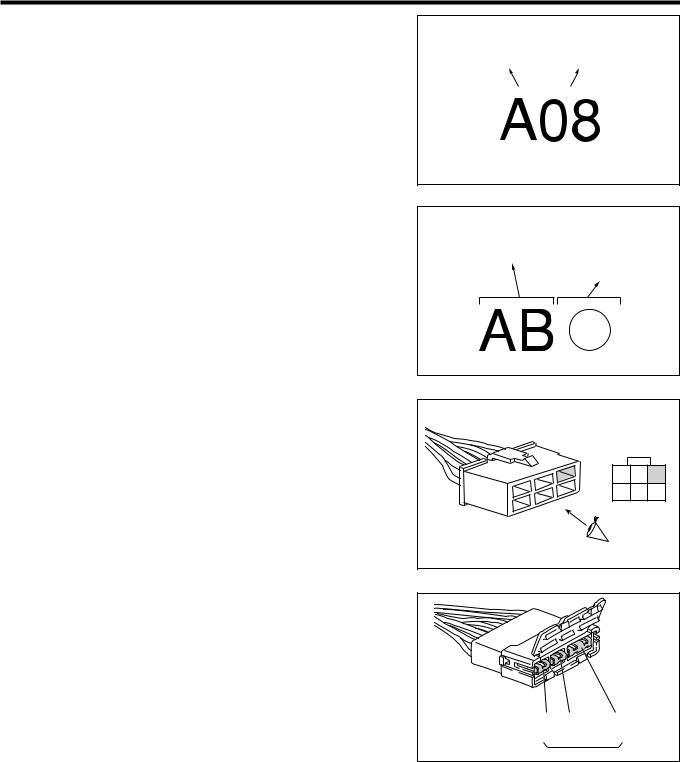
1.CONNECTOR NUMBER
(1)The part connector is indicated by a combination of single-digit alphabet and number. The alphabet represents the kind of harness, thus indicating harness which the part belongs to. The wire harness code is given at "9. WIRE HARNESS CODE TABLE" of this chapter. The number is a serial number, starting from 01.
(2)W to W is a combination of two-digit alphabets and two-digit numbers. The alphabets indicate the kind of harness, thus indicating which harness is connected to which harness. The wire harness code is given at "9. WIRE HARNESS CODE TABLE" of this chapter. The number is a serial number. The connector diagram indicates only the female connector side.
2.CONNECTOR TERMINAL NUMBER
(1)The connector terminal position indicates a position when the connector is viewed from the joint surface direction. Only the female connector side is indicated. Blank terminals are also given numbers.
(2)Those terminals shorted with the same short pin are enclosed with a heavy line in the J/C.
3.WIRE COLOR CODE
(1) The wire color in the circuit diagram is indicated by a code. The table showing the relationship between the code and color is given at right table.
Kind of harness |
Serial number starting |
|||
from 01 |
||||
|
|
|
|
|
|
|
|
|
|
M21W1012ET10
Means the kind of a wire.
W to W connector which connects
A wire and B wire.
M21W1013ET10 |
||
1 |
2 |
3 |
4 |
5 |
6 |
|
M21W1014T10 |
|
|
|
1 |
2 |
3 |
4 |
5 |
6 |
7 |
|
|
|
|
8 |
9 |
10 |
11 |
12 |
13 |
14 |
|
|
T11W1001T10
Code |
Color |
Code |
Color |
|
|
|
|
B |
Black |
V |
Violet |
|
|
|
|
G |
Green |
W |
White |
|
|
|
|
L |
Blue |
Y |
Yellow |
|
|
|
|
O |
Orange |
BR |
Brown |
|
|
|
|
P |
Pink |
GR |
Gray |
|
|
|
|
R |
Red |
LG |
Light green |
|
|
|
|
|
|
|
L21W1005ET10 |
A–5
(2)The wires come in two kinds; mono-color wires and dual color wires. The mono-color wire has only a basic color, whereas the dual color wire has stripes on the basic color background.
White(Basic color)
W
White(Basic color)
W-B
Black(Stripe color)
M21W1020ET10
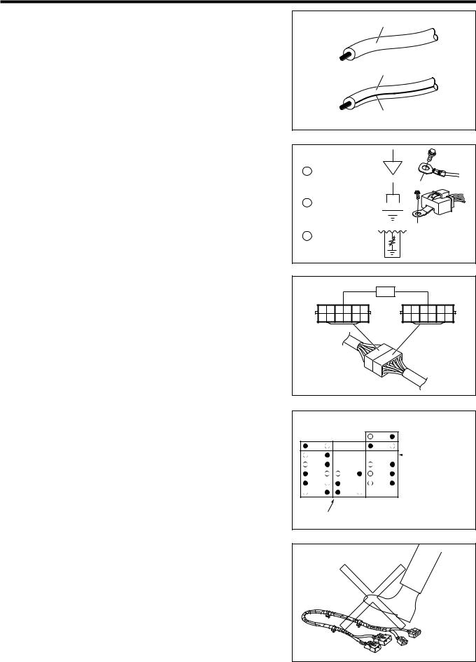
4.EARTH
(1) The circuit diagram by function in this manual explains three kinds of earth.
Bolt earth |
The terminal is directly bolted to the vehicle body. |
|
Connector earth |
More than one harness are combined to one connec- |
|
tor, then which is bolted to the vehicle body. |
||
|
||
Inside part earth |
Earth connection is made within a part, and this part is |
|
directly bolted to the vehicle body. |
||
|
5.WIRE TO WIRE JUNCTION CONNECTOR (W to W J/C)
(1)This connector is a junction connector in which a shorting pin shorts two connectors. The connector diagram of the W to W J/C is given at the right figure.
6.FUSE BLOCK, RELAY BLOCK
(1)The position of each fuse is indicated when the fuse block or relay block is viewed from the front. The
.mark indicates the power supply plus side of the fuse and the <mark indicates the power supply minus side of the fuse. No fuse is provided where no
. <mark is provided.
Xb
1 Bolt earth
1
Xc 2 Connector earth 


3 Inside part earth
|
|
|
|
|
|
|
|
|
|
M21W1016ET10 |
|
|
|
|
|
|
|
E50 |
|
|
|
|
|
1 |
2 |
3 |
4 |
5 |
6 |
6 |
5 |
4 |
3 |
2 |
1 |
7 |
8 |
9 |
10 |
11 12 |
12 11 |
10 9 |
8 |
7 |
|||
|
|
|
|
|
|
|
|
|
|
T11W1002T10 |
|
|
|
|
|
|
|
13 |
|
|
|
|
|
1 |
|
|
7 |
|
|
14 |
|
|
|
|
|
2 |
8 |
15 |
|
|
No fuse is set |
|
|
||||
3 |
9 |
16 |
|
|
|
4 |
10 |
17 |
|
|
|
|
|
|
|
|
|
5 |
11 |
18 |
|
|
|
6 |
12 |
19 |
|
|
|
 shows the power supply side
M21W1018ET10
3 HANDLING INSTRUCTIONS
3-1 HANDLING OF HARNESS AND CONNECTOR
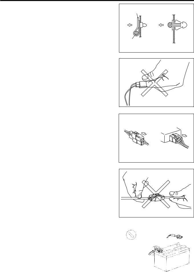
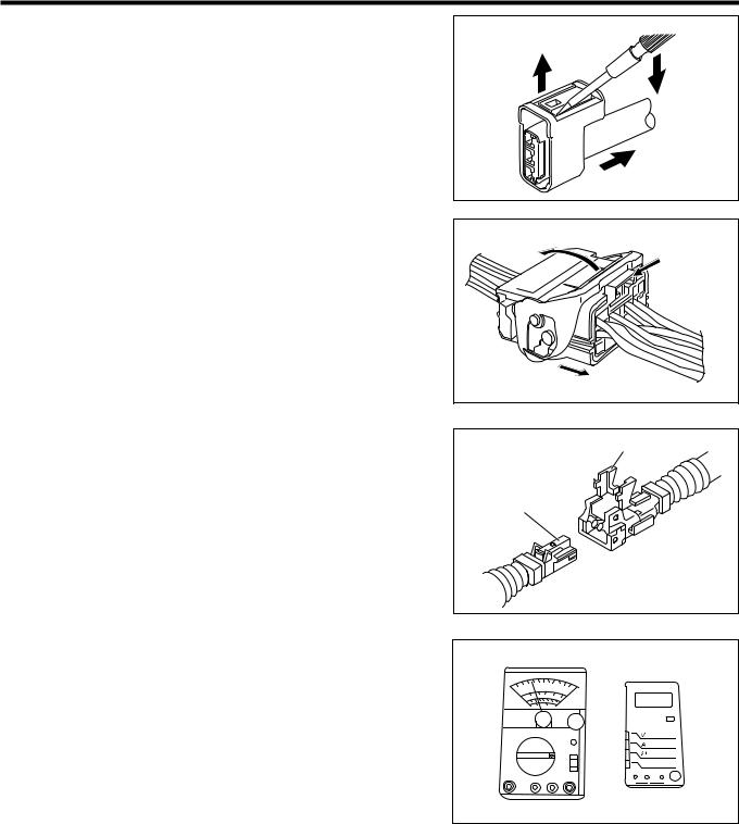
1.When assembling the wire harness, do not pull or step on the connectors. Be careful not to allow the harness to be damaged by burrs or edges.
2.When installing the harness, be careful not to allow the harness to wind or twist.
M21W1001T10
A–6
3.Ensure that the clamp section of the resin clamp has been inserted into the body hole.
CAUTION
•Ensure that the clamp section cannot be pulled out by lightly pulling it.
4.Never touch the terminal of connector directly by hand. 5.Modification of wire harness. The wire diameter and
capacity of each harness have been determined to assure the normal operation of the electrical system. Hence, do not take power for accessories carelessly through the original wiring harness. Failure to observe this caution may cause system malfunction or fire.
6.When a band type resin clamp is used, never use tools, such as pliers or radio pliers.
7.In the case of a locking connector, be sure to connect it firmly by pushing and inserting it. After connecting the connector, confirm that it has been locked by lightly pulling it.
8.Be careful not to pull out the connected connector by forcibly pulling the harness.
Clamp
Harness
M21W1002ET10
M21W1003T10
G07E5017T10
9.When disconnecting connectors, be sure to hold the connector itself with the connector unlocked.
M21W1004T10
10.Connection or disconnection of the connector and each |
|
|
terminal shall be performed basically after the removal of |
IG[OFF] |
|
negative terminal of the battery. |
||
|
||
CAUTION |
|
|
• However, there may be the case that diagnosis code is |
|
|
erased when remove the negative terminal of battery, |
|
|
so confirm the diagnosis code first before the removal |
|
|
of battery negative terminal when need to confirm. |
|
|
11.Check visually the rust generation or mixing of the foreign |
L11A5001T10 |
|
material at connector terminal portion. |
|
A–7
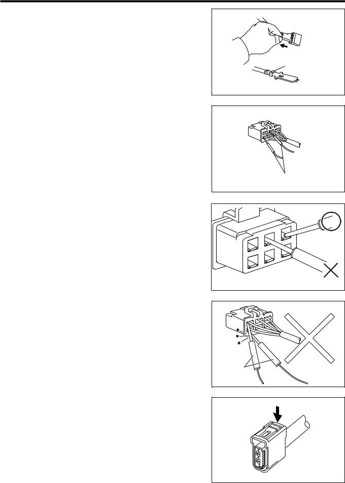
12.Check whether there are looseness, damage at the staking portion and check coming out from the coupler by pulling the wire harness lightly.
13.When inserting tester probes into a connector, insert them from the rear side of the connector.
Pull lightly
Looseness
G07E5022ET10
Tester probe
G07E5018ET10
14.For water-proof connectors which cannot be accessed from behind, take good care not to deform the connector terminals.
15.When a tester probe is applied to a terminal to which voltage is applied, care must be exercised so that two tester probes may not come in contact with each other so that short circuit may not take place.
Do not insert the tester probe in place.
G07E5024ET10 |
Tester probe |
M21W1005ET10 |
3-2 RELEASE OF CONNECTOR LOCK
3-2-1 PUSH TYPE
1.To pull out the connector, unlock the connector by pushing down the pawl of the locking section in the arrow direction with your finger or a tool.
1Press down
 2Pull
2Pull
M21W1006ET10
A–8
3-2-2 PULL-UP TYPE
1.To pull out the connector, unlock the connector by pushing up the pawl of the locking section in the arrow direction with your finger or a tool.
3-2-3 LEVER TYPE
1.Detach the pawl and raise the lock lever in the arrow direction. Then, the mating connector will be pushed out.
3-2-4 DOUBLE LOCK TYPE
1.First unlock the primary locking. Then, disconnect the connector by unlocking the secondary locking in the same way as the aforesaid push type connector.
1Raise the pawl
of the locking section
2Pull
M21W1007ET10
2Raise the lever
1Release the lock
3The connector will be pushed out
M21W1008ET10
Primary lock
Secondary lock
M21W1009ET10
3-3 INSPECTION
3-3-1 TESTER (VOLT/OHM METER)
1.For the inspection, use a tester having an internal resistance of more than 10 kilo-ohms/V. Use of a tester with a low internal resistance may cause wrong measurement or secondary troubles.
L21W1001ET10
A–9
3-3-2 VOLTAGE CHECK
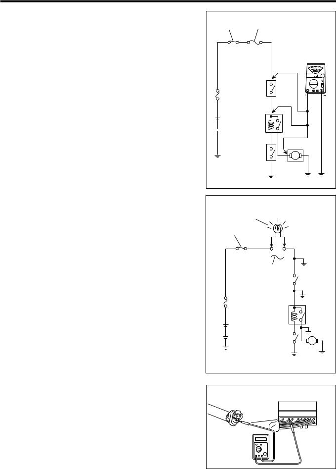
1.When conducting this check, let the voltage apply to the check point.
2.Connect the (() line of the voltmeter to the ground or (() terminal of the battery; the (') line to the connector terminal. This check can be performed by using a test lamp instead of a voltmeter.
Example
Check point |
Connecting condition |
A |
Ignition switch:ON |
B |
Ignition switch:ON, Switch A:ON |
C |
Ignition switch:ON, Switch A:ON, Switch B:ON, Relay:ON |
3-3-3 INSPECTION OF SHORT CIRCUIT
1.Remove a melt fuse or fusible link.
2.Disconnect all connectors for loads being applied to the melt fuse.
3.Connect a test lamp at the position where the melt fuse or fusible link was installed.
4.Search for the short circuit by providing the minimum conditions which make the test lamp glow.
5.Perform repairs or wiring harness replacement, as required.
Example
Short section |
Connecting condition |
A |
Ignition switch:ON |
B |
Ignition switch:ON, Switch A:ON |
C |
Ignition switch:ON, Switch A:ON, Switch B:ON, Relay:ON |
IG switch |
Fuse |
|
A |
Switch A |
|
|
B |
Battery |
|
|
C |
Switch B |
|
|
L21W1002ET20 |
Test lamp |
|
|
|
IG switch |
|
|
|
Short |
A |
|
|
Fuse |
|
|
|
Switch A |
|
|
|
Short |
B |
||
Short |
C |
||
Battery |
|
|
|
Switch B |
|
|
|
L21W1003ET20 |
|||
3-3-4 RESISTANCE AND CONTINUITY CHECK
1.Remove the connector of corresponding harness on both ends.
2.Measure the electrical resistance between corresponding terminals of connector on both end.
CAUTION
•Measure the electrical resistance while shaking wire harness in top and down and right and left lightly.
Sensor side |
Computer side |
|
+ |
|
G07E5020ET10 |
A–10
3.If a diode is built in the circuit, perform continuity test by |
|
changing the polarities of the measuring terminals. In |
|
case of a general type tester, ensure that continuity exists |
|
when the negative (() lead of the tester is connected to |
|
the positive (') side of the diode; the positive (') lead of |
|
the tester to the negative (() side of the diode. Also |
|
ensure that no continuity exists when the polarities are |
|
changed. Since some testers have different polarities, be |
|
sure to read the instruction manual of a tester to be used |
L21W1004ET10 |
for the check before using it. The inspection procedure for |
|
light emitting diodes (LED) is the same as normal diodes. |
|
However, there may be cases where the LED emits no |
|
light, unless a tester with LED check mode is used. If an |
|
adequate tester is not available, apply the battery voltage |
|
to the LED and ensure that the LED emits light. |
|
4 CAUTIONS ON HANDLING OF SRS AIRBAG
1.If the SRS airbag is not handled with the correct procedure and method, the airbag may be deployed unexpectedly during the operation, resulting in a serious accident. Moreover, if wrong repairs are made, there is the possibility that the airbag fails to operate when it should operate. Therefore, the airbag-related service (installation, check and replacement of parts) should be performed with the correct procedure and method. For that purpose, please read the repair manual carefully. Also, strictly observe the cautions about the airbag service.
L11A5031S16 |

A–11
5 ITEMS OMITTED IN THIS MANUAL
1.This manual does not cover the following item given below. When performing the electric system checks and service, please read the General section of this manual and related repair manuals. Moreover, before starting the check operations and service, be sure to be well versed in those operations by reading the General sections of the repair manuals.
(1)GENERAL SERVICE INSTRUCTION
(2)SUPPORTING POINTS FOR JACKS AND SAFETY STANDS
(3)SUPPORTING POINTS OF LIFTS
(4)SERVICE INSTRUCTIONS FOR FOUR WHEEL DRIVE VEHICLES
(5)DATA LINK CONNECTOR
(6)INSTRUCTIONS FOR SYSTEM INSPECTION
(7)INSTRUCTIONS FOR RADIO INSTALLATION
6 ABBREVIATION CODES
ABBREVIATION |
ORIGINAL WORD |
|
CODE |
||
|
||
2WD |
Two wheel drive |
|
4WD |
Four wheel drive |
|
ABS |
Anti-lock brake system |
|
ABV |
Air bypass valve |
|
A/B |
Airbag |
|
ACC |
Accessory |
|
ACV |
Air control valve |
|
A/C |
Air conditioner |
|
A/T |
Automatic transaxle, Automatic transmission |
|
DLC |
Data link connector |
|
E-A/T |
Electronic automatic transaxle, Electronic automatic transmission |
|
EBD |
Electronic brake force distribution |
|
ECU |
Electronic control unit |
|
EFI |
Electronic fuel injection |
|
EPS |
Electronic power steering |
|
FR |
Front |
|
F/L |
Fusible link |
|
G |
Gravity |
|
GND |
Ground |
|
IG |
Ignition |
|
ILL |
Illumination |
|
ISC |
Idle speed control |
|
J/C |
Junction connector |
|
LCD |
Liquid crystal display |
|
LED |
Light emitting diode |
|
LH |
Left-hand |
|
MIL |
Malfunction indicator lamp |
|
M/T |
Manual transaxle, Manual transmission |
|
P/S |
Power steering |
|
RAD |
Radiator |
|
RH |
Right-hand |
|
RR |
Rear |
|
R/B |
Relay block |
|
SRS |
Supplemental restrain system |
|
SW |
Switch |
|
TEMP. |
Temperature |
|
VSV |
Vacuum switching valve |
|
W to W |
Wire to wire connector |
A–12
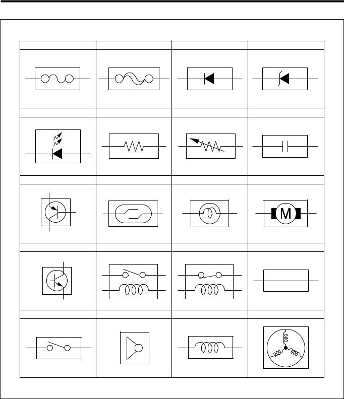
7 SYMBOL MARK
Fuse |
Fusible link |
Diode |
Zener diode |
LED |
Resistor |
Variable resistor |
Condenser |
PNP transistor |
Reed switch |
Bulb |
Motor |
NPN transistor |
Relay(Normally open) Relay(Normally closed) |
Shielding wire |
|
Switch |
Horn |
Solenoid |
Stator coil |
|
|
|
M21W1019ES40 |

A–13
8 MODEL VARIATION
GENERAL SPECIFICATION
Model code |
Steering position |
Engine |
Drive |
Transmission |
Body type |
|
M300RS(GMNE |
RHD |
1KR(FE |
2WD |
5M/T |
5(door |
|
M301RS(GMGE |
RHD |
K3(VE |
2WD |
5M/T |
5(door |
|
M301RS(GQGE |
RHD |
K3(VE |
2WD |
Electronic control |
5(door |
|
4A/T |
||||||
|
|
|
|
|
||
M300LS(GMNE |
LHD |
1KR(FE |
2WD |
5M/T |
5(door |
|
M301LS(GMGE |
LHD |
K3(VE |
2WD |
5M/T |
5(door |
|
M301LS(GQGE |
LHD |
K3(VE |
2WD |
Electronic control |
5(door |
|
4A/T |
||||||
|
|
|
|
|
EUROPEAN SPECIFICATION
Model code |
Steering position |
Engine |
Drive |
Transmission |
Body type |
|
M300RS(GMNEW |
RHD |
1KR(FE |
2WD |
5M/T |
5(door |
|
M301RS(GMGEW |
RHD |
K3(VE |
2WD |
5M/T |
5(door |
|
M301RS(GQGEW |
RHD |
K3(VE |
2WD |
Electronic control |
5(door |
|
4A/T |
||||||
|
|
|
|
|
||
M300LS(GMNEW |
LHD |
1KR(FE |
2WD |
5M/T |
5(door |
|
M301LS(GMGEW |
LHD |
K3(VE |
2WD |
5M/T |
5(door |
|
M301LS(GQGEW |
LHD |
K3(VE |
2WD |
Electronic control |
5(door |
|
4A/T |
||||||
|
|
|
|
|
AUSTRALIAN SPECIFICATION
Model code |
Steering position |
Engine |
Drive |
Transmission |
Body type |
|
M300RS(GMNEW |
RHD |
1KR(FE |
2WD |
5M/T |
5(door |
|
M301RS(GMGEW |
RHD |
K3(VE |
2WD |
5M/T |
5(door |
|
M301RS(GQGEW |
RHD |
K3(VE |
2WD |
Electronic control |
5(door |
|
4A/T |
||||||
|
|
|
|
|
9 WIRE HARNESS CODE TABLE
A |
Wire, Engine |
J |
( |
S |
Wire, Roof |
|
B |
Wire, Engine No.2 / Wire, Engine |
K |
( |
T |
Wire, Backdoor, No.1 |
|
No.3 |
||||||
|
|
|
|
|
||
C |
Wire, Engine room main |
L |
Wire, Front door (RHD) |
U |
( |
|
D |
Wire, Speed sensor |
M |
Wire, Front door (LHD) |
V |
( |
|
E |
Wire, Instrument panel (RHD) |
N |
Wire, Rear door |
W |
Wire, Rear window |
|
F |
Fuse, Relay |
O |
Wire, Floor |
X |
Earth |
|
G |
Wire, Instrument panel (LHD) |
P |
Wire, Floor, No.2 |
Y |
( |
|
H |
Wire, Lamp |
Q |
( |
Z |
( |
|
I |
( |
R |
( |
|
|
TO INDEX |
|
TO NEXT SECTION |

TO INDEX
A1 GENERAL INFORMATION |
A1 |
|
EXTERIOR, MODEL VARIATION, |
|
VEHICLE MODEL CODE -------------------- |
A1 - 1 |
EXTERIOR ------------------------------------ |
A1 - 1 |
MODEL VARIATION ------------------------ |
A1 - 2 |
EXPLANATION OF VEHICLE |
|
MODEL CODE ------------------------------- |
A1 - 2 |
SPECIFICATIONS ----------------------------- |
A1 - 3 |
VIEWS OF VEHICLE-------------------------- |
A1 - 4 |
VEHICLE IDENTIFICATION----------------- |
A1 - 5 |
LOCATION ------------------------------------ |
A1 - 5 |
ABBREVIATION CODES -------------------- |
A1 - 6 |

A1–1
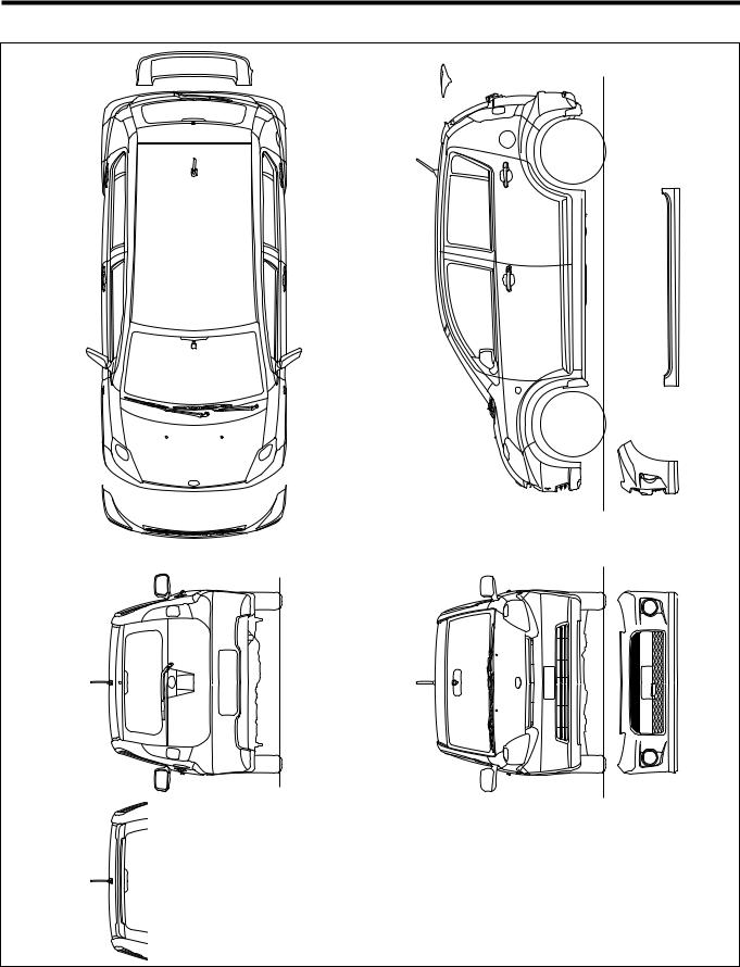
1 EXTERIOR, MODEL VARIATION, VEHICLE MODEL CODE
1-1 EXTERIOR
T11S1501S40
|
|
|
|
|
|
|
|
|
|
|
|
|
|
|
A1–2 |
1-2 |
MODEL VARIATION |
|
|
|
|
|
|
|
|
||||||
1-2-1 |
GENERAL SPECIFICATIONS |
|
|
|
|
|
|
|
|
||||||
|
|
|
|
|
|
|
|
|
|
|
|||||
|
|
Model code |
Steering position |
|
Engine |
|
|
|
Drive |
|
Transmission |
Body type |
|||
|
|
M300RS(GMNE |
|
RHD |
|
1KR(FE |
|
|
|
2WD |
|
5M/T |
5(door |
||
|
|
M301RS(GMGE |
|
RHD |
|
K3(VE |
|
|
|
2WD |
|
5M/T |
5(door |
||
|
|
M301RS(GQGE |
|
RHD |
|
K3(VE |
|
|
|
2WD |
|
Electronic control |
5(door |
||
|
|
|
|
|
|
|
|
4A/T |
|||||||
|
|
|
|
|
|
|
|
|
|
|
|
|
|
|
|
|
|
M300LS(GMNE |
|
LHD |
|
1KR(FE |
|
|
|
2WD |
|
5M/T |
5(door |
||
|
|
M301LS(GMGE |
|
LHD |
|
K3(VE |
|
|
|
2WD |
|
5M/T |
5(door |
||
|
|
M301LS(GQGE |
|
LHD |
|
K3(VE |
|
|
|
2WD |
|
Electronic control |
5(door |
||
|
|
|
|
|
|
|
|
4A/T |
|||||||
|
|
|
|
|
|
|
|
|
|
|
|
|
|
|
|
1-2-2 |
EU SPECIFICATIONS |
|
|
|
|
|
|
|
|
||||||
|
|
|
|
|
|
|
|
|
|
|
|
|
|||
|
|
Model code |
Steering position |
|
Engine |
|
|
|
Drive |
|
Transmission |
Body type |
|||
|
|
M300RS(GMNEW |
|
RHD |
|
1KR(FE |
|
|
|
2WD |
|
5M/T |
5(door |
||
|
|
M301RS(GMGEW |
|
RHD |
|
K3(VE |
|
|
|
2WD |
|
5M/T |
5(door |
||
|
|
M301RS(GQGEW |
|
RHD |
|
K3(VE |
|
|
|
2WD |
|
Electronic control |
5(door |
||
|
|
|
|
|
|
|
|
4A/T |
|||||||
|
|
|
|
|
|
|
|
|
|
|
|
|
|
|
|
|
|
M300LS(GMNEW |
|
LHD |
|
1KR(FE |
|
|
|
2WD |
|
5M/T |
5(door |
||
|
|
M301LS(GMGEW |
|
LHD |
|
K3(VE |
|
|
|
2WD |
|
5M/T |
5(door |
||
|
|
M301LS(GQGEW |
|
LHD |
|
K3(VE |
|
|
|
2WD |
|
Electronic control |
5(door |
||
|
|
|
|
|
|
|
|
4A/T |
|||||||
|
|
|
|
|
|
|
|
|
|
|
|
|
|
|
|
1-3 |
EXPLANATION OF VEHICLE MODEL CODE |
|
|
||||||||||||
|
|
M 3 0 0 R S ( G M N E W |
|
|
|
|
|
|
|
||||||
1 |
|
2 3 4 5 |
6 7 8 9 ! |
|
|
|
|
|
|
|
|||||
|
|
|
|
|
|
|
|
|
|
|
|
||||
|
|
1Model |
|
|
|
|
|
2Drive |
|
|
|||||
|
|
M3 |
: SIRION |
|
|
|
|
0 |
: 2WD |
|
|
||||
|
|
|
|
|
|
|
|
|
|
|
|
||||
|
|
3Engine |
|
|
|
|
|
4Steering |
|
|
|||||
|
0 |
: 1KR(FE |
|
|
|
|
|
L |
: LHD |
|
|
||||
|
1 |
: |
K3(VE |
|
|
|
|
|
R |
: RHD |
|
|
|||
|
|
|
|
|
|
|
|
|
|
|
|
||||
|
|
5Body type |
|
|
|
|
|
6Door |
|
|
|||||
|
|
S |
: |
Sedan |
|
|
|
|
|
G |
: |
5(door |
|
|
|
|
|
|
|
|
|
|
|
|
|
|
|
||||
|
|
7Transmission |
|
|
|
|
|
8Grade |
|
|
|||||
|
|
M |
: |
5M/T |
|
|
|
|
|
N |
: |
STD(1.0L) |
|
|
|
|
|
Q |
: |
Electronic control 4A/T |
|
|
G |
: |
STD(1.3L) |
|
|
||||
|
|
|
|
|
|
|
|
|
|
|
|
||||
|
|
9Fuel system |
|
|
|
|
|
!Market |
|
|
|||||
|
|
E |
: DOHC |
|
|
|
|
|
None |
: General |
|
|
|||
|
|
|
|
|
|
|
|
|
|
W |
|
: EU / AUS |
|
|
|
|
|
|
|
|
|
|
|
|
|
|
|
|
|
|
|

A1–3
2 SPECIFICATIONS
|
|
|
|
M300LS/M300RS |
|
|
M301LS/M301RS |
|
||||
|
|
|
|
GMNE |
GMNEW |
|
GMGE |
GQGE |
|
GMGEW |
GQGEW |
|
|
|
Engine |
|
1KR(FE |
|
|
K3(VE |
|
||||
|
|
Market |
|
General |
EU, AUS |
|
General |
General |
|
EU, AUS |
EU, AUS |
|
Items |
|
Drive |
|
5M/T |
5M/T |
|
5M/T |
E4A/T |
|
5M/T |
|
E4A/T |
Overall length |
|
|
mm |
|
|
3600 |
|
|
|
|
||
|
With Aero Bumper |
mm |
( |
|
|
3630 |
|
|
||||
Overall width |
|
|
mm |
|
|
1665 |
|
|
|
|
||
Overall height |
|
|
mm |
|
|
1550 |
|
|
|
|
||
Interior length |
|
|
mm |
|
|
1830 |
|
|
|
|
||
Interior width |
|
|
mm |
|
|
1400 |
|
|
|
|
||
Interior height |
|
|
mm |
|
|
1275 |
|
|
|
|
||
Wheelbase |
|
|
mm |
|
|
2430 |
|
|
|
|
||
Tread |
13 " tire |
Front |
mm |
1470 |
|
|
( |
|
|
|||
|
|
Rear |
mm |
1475 |
|
|
( |
|
|
|||
|
14 " tire |
Front |
mm |
|
|
1460 |
|
|
|
|
||
|
|
Rear |
mm |
|
|
1465 |
|
|
|
|
||
Minimum road clearance |
|
|
mm |
|
|
150 |
|
|
|
|
||
Min Turning Radius |
13 " tire |
|
m |
4.3 (Tire), 4.7 |
|
|
( |
|
|
|||
|
|
|
|
(Body) |
|
|
|
|
|
|
|
|
|
14 " tire |
|
m |
|
|
4.7 (Tire), 5.1 (Body) |
|
|
|
|||
Kerb weight |
|
|
kg |
875 |
890 |
|
925 |
940 |
|
955 |
||
Gross vehicle weight |
General, EU |
|
kg |
1380 |
1390 |
|
|
1450 |
|
|
||
|
AUS |
|
kg |
( |
1320 |
|
( |
|
1380 |
|||
Seating capacity |
|
|
persons |
|
|
|
Front : 2, Rear : 3 |
|
|
|
||
Engine type |
|
|
|
1KR(FE |
|
|
K3(VE |
|
||||
Total displacement |
|
|
cc |
998 |
|
|
1298 |
|
|
|||
Bore)stroke |
|
|
mm |
71.0)84.0 |
|
|
72.00)79.70 |
|
|
|||
Max. output |
|
|
kw/rpm |
51.0/6000 |
|
|
64.0/6000 |
|
|
|||
Max. Torque |
|
|
Nm/rpm |
94.0/3600 |
|
|
120.0/3200 |
|
|
|||
Compression ratio |
|
|
|
10.5&0.3 |
|
|
10&0.3 |
|
|
|||
Fuel system |
|
|
|
|
EFI (Electronic fuel injection) |
|
||||||
Fuel tank capacity |
|
|
Litres |
|
|
40 |
|
|
|
|
||
Clutch |
5M/T |
|
|
Dry single plate with diaphragm spring and mechanical |
||||||||
|
|
|
|
|
|
|
actuation |
|
|
|
||
|
4A/T |
|
|
|
3-element, 1-stage, 2-phase |
|
||||||
Transmission |
5M/T |
|
|
Forward 5-speed, manual, all synchromesh |
|
|||||||
|
4A/T |
|
|
|
Forward 4-speed full automatic |
|
||||||
Transmission gear ratio |
1KR(FE |
5M/T |
|
1st:3.182, 2nd:1.842, 3rd:1.250, 4th:0.917, 5th:0.750, |
||||||||
|
|
|
|
|
|
|
rev:3.143 |
|
|
|
||
|
K3(VE |
5M/T |
|
1st:3.182, 2nd:1.842, 3rd:1.250, 4th:0.865, 5th:0.750, |
||||||||
|
|
|
|
|
|
|
rev:3.143 |
|
|
|
||
|
|
4A/T |
|
1st:2.731, 2nd:1.526, 3rd:1.00, 4th:0.696, rev:2.290 |
||||||||
Final reduction gear ratio |
1KR(FE |
5M/T |
|
|
|
4.500 |
|
|
|
|
||
|
K3(VE |
5M/T |
|
|
|
4.267 |
|
|
|
|
||
|
|
4A/T |
|
|
|
4.032 |
|
|
|
|
||
Steering type |
|
|
|
|
|
|
Rack&Pinion |
|
|
|
||
Main brakes |
Front |
|
|
|
Disk brakes with booster |
|
||||||
|
Rear |
|
|
|
Drum brakes, leading and trailing |
|
||||||
Parking brake |
|
|
|
|
Mechanically oprerating on rear wheels |
|
||||||
Suspension |
Front |
|
|
|
MacPherson struts with coil springs |
|
||||||
|
Rear |
|
|
Semi-independent torsion axle beam with coil springs |
||||||||
Tires |
13 " tire |
|
|
155/80R13 |
|
|
( |
|
|
|||
|
14 " tire |
|
|
|
|
|
175/65R14 |
|
|
|
||
Trailer towing |
without brake |
|
kg |
|
|
350 |
|
|
|
|
||
|
with brake |
|
kg |
750 |
|
|
1000 |
|
|
|||
Permissible roof rack load |
|
|
kg |
|
|
50 |
|
|
|
|
||
A1–4
3 VIEWS OF VEHICLE
T11S1511S45
A1–5
4 VEHICLE IDENTIFICATION
4-1 LOCATION
4-1-1 VEHICLE IDENTIFICATION NUMBER
4-1-2 ENGINE TYPE AND ENGINE NUMBER
4-1-3 MANUFACTURER'S PLATE POSITION
Vehicle identification number (for GCC,EU & South Africa specifications)
Vehicle identification number T11S5530ET10
Engine type
Engine number
T11S5531ET10
Engine type
Engine number
T11S5532ET10
Manufacturer’s plate
T11S5533ET10
|
|
|
|
A1–6 |
5 ABBREVIATION CODES |
|
|
||
|
|
|
|
|
|
ABBREVIATION CODE |
ORIGINAL WORD |
ABBREVIATION CODE |
ORIGINAL WORD |
|
|
|
|
|
|
2WD |
Two Wheel Drive |
LHD |
Left Hand Drive |
|
|
|
|
|
|
4WD |
Four Wheel Drive |
LIN |
Local Interconnect Netwark |
|
|
|
|
|
|
ABS |
Anti-lock Brake System |
LSPV |
Load Sensing Proportioning Valve |
|
|
|
|
|
|
ABV |
Air Bypass Valve |
LWR |
Lower |
|
|
|
|
|
|
A/C |
Air Conditioner |
MIL |
Malfunction Indicator Lamp |
|
|
|
|
|
|
ACC |
Accessory |
MP |
Multipurpose |
|
|
|
|
|
|
API |
American Petroleum Institute |
M/T |
Manual Transmission |
|
|
|
|
|
|
A/T |
Automatic Transmission |
N/A |
Natural Aspiration |
|
|
|
|
|
|
ATDC |
After Top Dead Center |
NOx |
Nitrogen Oxides |
|
|
|
|
|
|
ATF |
Automatic Transmission Fluid |
OPT |
Option |
|
|
|
|
|
|
Ay |
Assembly |
O/S |
Over Size |
|
|
|
|
|
|
BDC |
Bottom Dead Center |
PCV |
Positive Crankcase Ventilation |
|
|
|
|
|
|
BTDC |
Before Top Dead Center |
PR |
Ply Rating |
|
|
|
|
|
|
BVSV |
Bimetal Vacuum Switching Valve |
PTO |
Power Take Off |
|
|
|
|
|
|
CAN |
Controller Area Network |
RH |
Right Hand |
|
|
|
|
|
|
CD |
Compact Disc |
RHD |
Right Hand Drive |
|
|
|
|
|
|
CO |
Carbon Monoxide |
RR |
Rear |
|
|
|
|
|
|
DLC |
Data Link Connector |
S/A |
Sub-Assembly |
|
|
|
|
|
|
DLI |
Distributor Less Ignition |
SAE |
Society of Automotive Engineers |
|
|
|
|
|
|
DTC |
Diagnostic Trouble Code |
SRS |
Supplemental Restraint System |
|
|
|
|
|
|
DVVT |
Dynamic Variable Valve Timing |
SST |
Special Service Tool |
|
|
|
|
|
|
EBD |
Electronic Brake force Distribution |
STD |
Standard |
|
|
|
|
|
|
ECU |
Electronic Control Unit |
SW |
Switch |
|
|
|
|
|
|
EFI |
Electronic Fuel Injection |
T |
Torque |
|
|
|
|
|
|
EGR |
Exhaust Gas Recirculation System |
T/C |
Turbocharger |
|
|
|
|
|
|
EPS |
Electronic controlled Power Steering |
TDC |
Top Dead Center |
|
|
|
|
|
|
ESA |
Electronic Spark Advance |
UPR |
Upper |
|
|
|
|
|
|
EX |
Exhaust |
U/S |
Under Size |
|
|
|
|
|
|
F/L |
Fusible Link |
VCV |
Vacuum Control Valve |
|
|
|
|
|
|
FR |
Front |
VSV |
Vacuum Switching Valve |
|
|
|
|
|
|
GND |
Ground |
VTV |
Vacuum Transmitting Valve |
|
|
|
|
|
|
HC |
Hydro Carbon |
W/ |
With |
|
|
|
|
|
|
IG |
Ignition |
WVTA |
Whole Vehicle Type Approval |
|
|
|
|
|
|
IN |
Intake |
B |
Bolt |
|
|
|
|
|
|
ISC |
Idle Speed Control |
S |
Screw |
|
|
|
|
|
|
ISO |
International Organization for Stan- |
N |
Nut |
|
dardization |
|||
|
|
|
|
|
|
LCD |
Liquid Crystal Display |
W |
Washer |
|
|
|
|
|
|
LED |
Light Emitting Diode |
C |
Clip |
|
|
|
|
|
|
LH |
Left Hand |
|
|
|
|
|
|
|
TO INDEX |
|
TO NEXT SECTION |

TO INDEX
B POWER SUPPLY SYSTEM DIAGRAM
POWER SUPPLY SYSTEM DIAGRAM---- B - 1
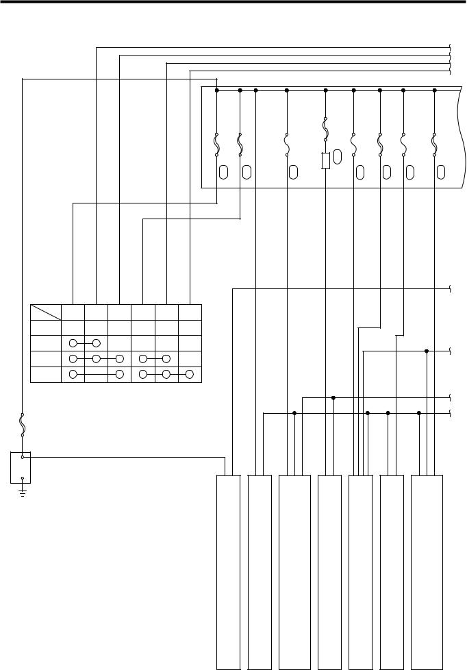
B–1
1 POWER SUPPLY SYSTEM DIAGRAM
|
|
|
|
|
|
|
|
|
|
|
|
|
a |
|
|
|
|
|
|
|
|
|
|
|
|
|
b |
|
|
|
|
|
|
|
|
|
|
|
|
|
c |
|
|
|
|
|
|
|
|
|
|
|
|
|
d |
|
|
|
|
|
|
|
|
Relay block |
|
|
|
|
|
|
|
|
|
|
6(AM1,50A) |
4(AM2,30A) |
9(EFI,15A) |
RAD FAN relay |
FA 3(RAD,30A) |
21(ABS2,20A) |
5(ABS1,40A) |
20(ECU-B,10A) |
7(EPS,50A) |
|
|
|
|
|
FA |
FA |
FA |
|
|
FA |
FA |
FA |
FA |
|
|
|
|
|
|
|
|
|
|
|
|
|
e |
AM1 |
ACC |
IG1 |
AM2 |
IG2 |
ST |
|
|
|
|
|
|
|
|
LOCK |
|
|
|
|
|
|
|
|
|
|
|
|
|
ACC |
|
|
|
|
|
|
|
|
|
|
|
|
|
|
|
|
|
|
|
|
|
|
|
|
|
|
f |
ON |
|
|
|
|
|
|
|
|
|
|
|
|
|
START |
|
|
|
|
|
|
|
|
|
|
|
|
|
Ignition switch |
|
|
|
|
|
|
|
|
|
|
|
|
|
|
|
|
|
|
|
|
|
|
|
|
|
|
g |
|
|
|
|
|
|
|
|
|
|
|
|
|
h |
FL2.0 |
|
|
|
|
|
|
|
|
|
|
|
|
|
+ |
|
|
|
|
|
|
|
|
|
|
|
|
|
Battery |
|
|
|
|
|
|
|
|
|
|
|
|
|
- |
|
|
|
|
2 |
3 |
4 |
|
5 |
6 |
|
7 |
8 |
|
|
|
|
|
|
|
|||||||
STARTING SYSTEM |
CHARGING SYSTEM |
ENGINE CONTROL SYSTEM |
RADIATOR FAN |
ABS |
A/T CONTROL |
ELECTRIC POWER STEERING |
T11Q5223ES48
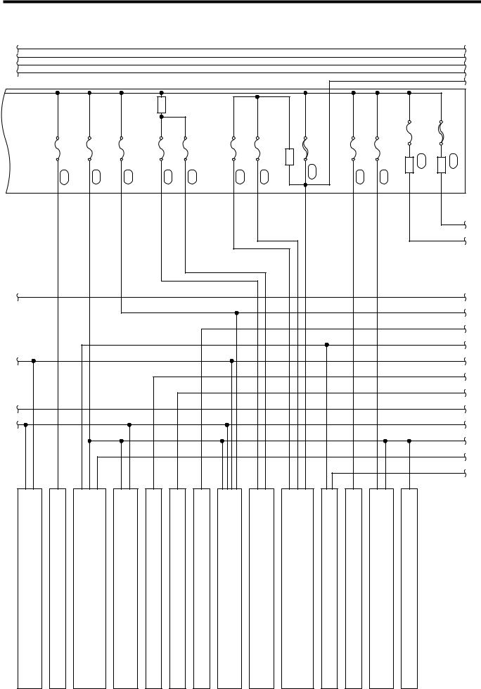
B–2
a |
|
|
|
|
|
|
|
|
|
|
|
|
|
a |
b |
|
|
|
|
|
|
|
|
|
|
|
|
|
b |
c |
|
|
|
|
|
|
|
|
|
|
|
|
|
c |
d |
|
|
|
|
|
|
|
|
|
|
|
|
|
d |
|
|
|
Relay block |
|
|
|
|
|
|
|
|
|
i |
|
|
|
|
|
|
|
|
|
|
|
|
|
|
||
|
|
|
Headlamp |
|
|
|
|
|
|
|
|
|
|
|
|
|
|
relay |
|
|
|
|
|
|
|
|
|
|
|
FA 23(DOME,7.5A) |
FA 24(BACK UP,15A) |
FA 10(HORN,10A) |
FA 15(H-LP RH, 10A) |
FA 16(H-LP LH, 10A) |
FA 13(FOG RH,10A) |
FA 14(FOG LH,10A) |
Fog lamp relay |
FA 8(IG,50A) |
FA 12(STOP,15A) |
FA 22(TAIL,10A) |
MGC relay |
FA 11(MGC,10A) |
Heater relay |
FA 1(HEATER,40A) |
j
k
e |
e |
|
m |
|
n |
|
o |
f |
f |
|
p |
|
q |
g |
g |
h |
h |
|
r |
|
s |
|
t |
9 |
10 |
11 |
12 |
13 |
14 |
15 |
16 |
17 |
18 |
19 |
20 |
21 |
22 |
SRS AIRBAG SYSTEM |
DOME LAMP |
POWER DOOR LOCK, KEY-LESS ENTRY SYSTEM |
IMMOBILIZER SYSTEM |
OUTER REAR-VIEW MIRROR |
REAR WINDOW DEFOGGER |
POWER WINDOW |
METER |
HEADLAMP |
FOG LAMP |
HAZARD WARNING & TURN SIGNAL LAMP |
STOP LAMP |
TAIL & LICENSE PLATE LAMP |
BACK UP LAMP |
T11Q5224ES48
B–3
a |
|
|
|
|
|
|
|
|
|
|
|
b |
|
|
|
|
|
|
|
|
|
|
|
c |
|
|
|
|
|
|
|
|
|
|
|
d |
|
|
|
|
|
|
|
|
|
|
|
i |
|
|
|
|
|
|
|
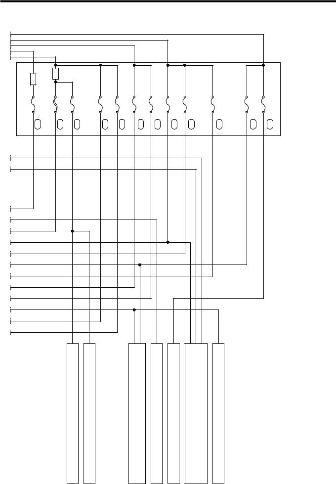
Fuse block |
|
|
|
|
|
|
|
|
|
|
|
|
|
|
|
Starter relay |
IG relay |
|
|
|
|
|
|
|
|
|
|
1(ST,7.5A) |
7(PWR,30A) |
6(WIP WSHR,20A) |
2(D/LOCK,15A) |
4(HAZ,10A) |
9(E/G,10A) |
10(ECU IG2,7.5A) |
12(IG1/BACK, 7.5A) |
13(ECU IG1, 7.5A) |
11(DEFG,20A) |
14(ACC,7.5A) |
15(CIG,15A) |
FB |
FB |
FB |
FB |
FB |
FB |
FB |
FB |
FB |
FB |
FB |
FB |
j
k
e
m
n
o
f
p
q
g
h
r
s
t
23 |
24 |
25 |
26 |
27 |
28 |
29 |
FRONT WIPER & WASHER |
REAR WIPER & WASHER |
RADIO |
HORN |
CIGARETTE LIGHTER,POWER OUTLET |
HEATER & AIR CONDITIONER |
DATA LINK CONNECTOR |
T11Q5225ES48
TO INDEX |
|
TO NEXT SECTION |

TO INDEX
B1 ENGINE DESCRIPTION
B1
1KR ---------------------------------------------------- |
B1 - 1 |
OUTLINE ----------------------------------------- |
B1 - 1 |
SPECIFICATIONS ---------------------------- |
B1 - 3 |
SECTIONAL VIEW ---------------------------- |
B1 - 4 |
PERFORMANCE CURVE ------------------- |
B1 - 5 |
K3 ------------------------------------------------------ |
B1 - 6 |
OUTLINE ----------------------------------------- |
B1 - 6 |
SPECIFICATIONS ---------------------------- |
B1 - 7 |
SECTIONAL VIEW ---------------------------- |
B1 - 8 |
PERFORMANCE CURVE------------------ |
B1 - 10 |

B1–1
Ä1KR
1 OUTLINE
On M 300 Series, a newly-designed Type 1KR-FE engine has been mounted transversely.
Type 1KR-FE engine is an in-line 3-cylinder water-cooled engine with a displacement of 0.996 liter that has been developed, aiming at excellent fuel economy, low noise level, low vibration, light weight and main- tenance-free feature.
The vehicles mounted with Type 1KR engine have two different specifications, depending upon the applicable exhaust emission control standards, i.e. the general destination specification and EU destination specification. The general specification vehicles have complied with the exhaust emission control standard, ECE83-03 (the normally-called Euro2) through changing the EFI system specifications as well as the employment of the optimized control. etc. Moreover, the EU specification vehicles have complied with the exhaust emission control standard: EEC:2003/76/(70/220), EEC:R83-05 (the normally-called Euro4) through changing the EFI system specifications and employing the optimized control, etc, combined with the intelligent catalyst.
Furthermore, all the EU specification vehicles have achieved the fuel consumption standard 2004/3 (80/1268).
1.FEATURES
(1) LOW FUEL CONSUMPTION
The intake and exhaust efficiencies have been improved through the employment of a valve actuating mechanism with DOHC4 valves with a variable valve timing device and a longitudinal type straight intake port.
A higher compression ratio has been achieved through a compact combustion chamber and improved cooling around the combustion chamber. Also, the combustion efficiency has been improved.
The resistance related to the pistons has drastically been reduced through the employment of a reduced thrust load of piston due to the adoption of an offset crankshaft, the application of a new type resin coating to the pistons and reduced piston ring tensions.
The pumping loss has been reduced through the employment of DVVT equipment and the introduction of EGR gas in the medium and low loading ranges.
(2) LOW VIBRATION AND LOW NOISE LEVEL
The engine vibration has been reduced and joint rigidity has been improved by adopting a high rigidity aluminum block and a high rigidity aluminum oil pan.
The tapping noise and bending vibration have been reduced by employing a forged individually balanced crankshaft.
The engine mount vibration has been reduced by integrating the engine mount bracket with the chain cover.
(3) COMPACT SIZE AND LIGHT WEIGHT
The cylinder head-related components have been designed compactly with reduced weight by employing a direct-tapping type DOHC.
The weight has been reduced by employing resin intake manifold, throttle body and head cover.
(4) MAINTENANCE
The maintenance-free feature has been achieved by employing a timing chain equipped with an auto tensioner.
The employment of an element replacement type oil filter has reduced the environmental load substance during the recycling period.
B1–2
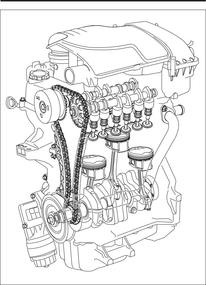
Engine perspective view
T11E2001S48 |

B1–3
2 SPECIFICATIONS
Engine specificatons
|
Engine type |
|
TYPE 1KR-FE |
|
|
|
Kind |
|
Gasoline-fueled, water-cooled 4-cycle |
Number of cylinders and arrangement |
|
3-cylinder in line, transversely mounted |
||
|
Valve mechanism |
|
Chain driven, DOHC (IN2, EX2) |
|
|
Combustion chamber |
|
Pent roof |
|
Intake and exhaust layout |
|
Cross-flow type |
||
|
Total displacement (cc) |
|
998 |
|
|
Bore ) Stroke (mm) |
|
71.0)84 |
|
|
Compression ratio |
|
10.5&0.3 |
|
Maximum output (kW) [rpm] |
|
51.0/6000 |
||
Maximum torque (N;m) [rpm] |
|
94.0/3600 |
||
Valve Timing |
|
Intake |
Open |
40$-(5$ BTDC |
|
|
|
Close |
10$-55$ ABDC |
|
|
Exhaust |
Open |
40$ BBDC |
|
|
|
Close |
2$ ATDC |
|
Fuel supplying device |
|
Electronically controlled fuel injection system (EFI) |
|
|
Ignition method |
|
Full-transistorized DLI type battery ignition |
|
|
Idle revolution speed |
|
800&50 |
|
|
Lubricant used |
|
|
|
|
|
|
|
SAE 0W-20 or 5W-30 API SG or higher |

B1–4
3 SECTIONAL VIEW
Engine cross-section view
3Longitudinal cross-section5 |
3Transverse cross-section5 |
T11E2002ES48 |
 Loading...