


& TECHNICAL INFORMATION &
BODY REPAIR MANUAL & P.D.I MANUAL
Chassis
NO.9890
TYPE 1KR ENGINE
NO.9893
Pre-delivery
Inspection Manual
PASSENGER VEHICLES
COMMERCIAL VEHICLES
PDI
NO.9807
Wiring diagram
NO.9891
BODY REPAIR MANUAL
NO. 9892
TECHNICAL INFORMATION
NO. 9402
QUITIT

A.GENERAL INFORMATION
B.ENGINE UNIT
C.ENGINE ELECTRICAL
D.SERVICE SPECIFICATIONS

TO INDEX
A GENERAL INFORMATION
PURPOSE OF THIS MANUAL------------- |
A-1 |
WHAT IS PDI? -------------------------- |
A-1 |
MAIN POINTS OF INSPECTION --------- |
A-1 |
IMPORTANCE OF BEING VERSED IN |
A-1 |
OWNER'S MANUAL -------------------- |
|
NECESSITY OF CHECK PRIOR TO VE |
A-1 |
HICLE DELIVERY TO USER ------------- |
|
REPORT OF INSPECTION RESULTS----- |
A-1 |

A-1
1 PURPOSE OF THIS MANUAL
This manual has been prepared to help the distributors or dealers perform the PDI (Pre-Delivery Inspection) properly and promptly. This manual mainly describes the PDI operations (including inspection items, procedures and methods) to be conducted by servicemen as they perform the inspection for new vehicles.
Be sure to read this manual carefully and perform the PDI according to the instructions given below.
1-1 WHAT IS PDI?
In the PDI (Pre-Delivery Inspection), the distributors or dealers check to see if vehicles are in the proper conditions as new vehicles, and if functional parts or each section of the vehicle functions properly.
1-2 MAIN POINTS OF INSPECTION
The inspection covers all the items that can be checked visually or by hand.
1.Visual inspection and hand inspection
(1)Paint condition
(2)Scratches
(3)Rust
(4)Mud
(5)Discoloration
(6)Deformation
(7)Installing condition
2.Functional check
(1)Check to see if the part functions properly.
(2)Check to see if the part functions smoothly.
(3)Check to see if there is any abnormal noise or vibration.
If any problem is found as to the check items above, take necessary measures before the vehicle is delivered to the user.
1-3 IMPORTANCE OF BEING VERSED IN OWNER'S MANUAL
The equipment and functions differ, depending upon models. Even in the same model, the equipment and functions differ depending upon grades and destinations. Since this manual has been prepared for vehicles for all destinations, the PDI operations for general mechanisms and equipment are described. Moreover, some of the illustrations in this manual may show vehicles that are different from the vehicle that you are checking, as this manual covers all the models.Therefore, to perform the PDI perfectly, the servicemen must read the owner's manual carefully and be well versed in the basic mechanisms and functions of the vehicle and equipment that is going to be checked.
1-4 NECESSITY OF CHECK PRIOR TO VEHICLE DELIVERY TO USER
During the period between the completion of the PDI and the vehicle delivery to users, the vehicles are subject to various conditions when they are exhibited in a show room, stored in a warehouse or installed with optional equipment. During this period, the vehicle may be damaged in some ways. It is, therefore, imperative to perform an inspection prior to deliver to users, according to the section "VEHICLE DELIVERY INSPECTION ITEMS."
1-5 REPORT OF INSPECTION RESULTS
In order to incessantly improve the quality of new vehicles, please send the Field Technical Report to DMC through the distributor when you encounter some problems that occur frequently due to poor quality of vehicles shipped from the factory.
TO INDEX |
|
TO NEXT SECTION |

TO INDEX
A GENERAL INFORMATION
HOW TO USE THIS MANUAL |
A - 1 |
|
|
||
SCOPE OF DESCRIPTION IN THIS |
|
|
MANUAL ---------------------------------------- |
A - 1 |
|
ARTICLES TO BE PREPARED ----------- |
A - 1 |
|
COMPONENTS ------------------------------- |
A - 1 |
|
CONTENTS NOT DESCRIBED IN |
|
|
THIS MANUAL--------------------------------- |
A - 3 |
|
DEFINITIONS OF TERMS ----------------- |
A - 3 |
|
ABBREVIATION CODES ------------------- |
A - 3 |
|
UNIT------------------------------------------------- |
A - 4 |
|
NEW UNIT BECAUSE OF THE |
|
|
INTRODUCTION OF THE SI UNIT ------ |
A - 4 |
|
PREFIX USER IN SI UNIT ----------------- |
A - 4 |
|
HOW TO GRASP SPECIFIED |
|
|
TIGHTENING TORQUE FOR |
|
|
GENERAL STANDARD BOLT AND |
|
|
NUT-------------------------------------------------- |
A - 5 |
|
DETERMINING PROCEDURE FOR |
|
|
TIGHTENING TORQUE FOR |
|
|
GENERAL STANDARD BOLTS AND |
|
|
NUTS--------------------------------------------- |
A - 5 |
|
INSTRUCTIONS ON SERVICING |
|
|
OPERATIONS OF ENGINE AY -------------- |
A - 8 |
|

A–1
1 HOW TO USE THIS MANUAL
1-1 SCOPE OF DESCRIPTION IN THIS MANUAL
This manual describes the "Disassembling and Assembling Procedure" for Type 1KR-FE engine assembly. As for the procedure for removal and installation from and to the vehicle as well as the procedures for oil supply, checks and adjustment after completion of mounting on the vehicle, these procedures are described in the repair manual of respective vehicle models.
1-2 ARTICLES TO BE PREPARED
When SST, tool, measuring instrument, a sort of fat and oil to be prepared before operation are necessary, those are described by compiling in the table as preparation tools at the beginning of each item. However, the general tools, jacks, fixtures as considered being equipped always at the service shop are usually omitted.
1-3 COMPONENTS
1.The cross-sectional views and component diagrams are provided, thus showing the installation condition of each part.
2.Non-reusable parts are also described in the component diagrams. The explanation of relevant numerals is given below the component diagrams.
3.The removal, disassembling and assembling procedure list is shown just beneath of components figure.

|
|
|
|
|
A–2 |
1-3-1 ENTRY EXAMPLE |
|
|
|
|
|
|
B T:10.0&3.0 {102&31} |
T:7.7&1.5 {79&15} |
B |
||
|
|
|
|
|
4 |
|
|
|
T:7.7&1.5 {79&15} |
N |
|
|
1 |
|
2 |
|
|
|
|
|
~3 |
|
|
|
T:24.0&4.8 {245&48} |
B |
|
|
~5 |
|
|
|
|
|
|
|
T:24.0&4.8 {245&48} |
B |
|
|
|
|
|
|
14 |
|
|
T:24.0&4.8 {245&48} |
|
|
|
|
|
|
B |
~7 |
|
|
|
|
|
|
|
|
|
T:180.0&10.8 {1836&110} |
|
|
|
|
|
|
6 |
|
~15 |
|
|
|
|
|
|
|
|
|
|
|
~9 |
|
|
|
|
|
8 |
|
|
|
|
|
~12 |
|
|
13 |
T:26.0&3.4 {265&34} B |
|
|
|
|
|
|
|
|
||
|
|
|
11 |
|
|
|
T:26.0&3.4 {265&34} |
B |
B |
|
|
|
|
|
T:8.5&1.7 {87&17} |
|
10 |
|
|
|
|
|
|
|
|
|
|
|
T11E9102_1S40 |
kEngine oil |
|
|
|
|
|
Unit: N;m{kgf;cm} |
|
|
|
|
|
~: Non-reusable parts |
|
|
|
|
|
1 |
Gage S/A, oil level |
9 |
Gasket, water pump |
2 |
Guide S/A, oil level gage |
10 |
Pan S/A, oil |
3 |
Ring, O |
11 |
Plate, oil pan baffle |
4 |
Cover Ay, cylinder head |
12 |
Strainer S/A, oil |
5 |
Gasket, cylinder head cover |
13 |
Gasket, oil strainer |
6 |
Bracket, oil filter |
14 |
Pulley, crankshaft |
7 |
Gasket, oil filter |
15 |
Cover Ay, timing chain |
8 |
Pump Ay, water |
16 |
Seal, type T oil |

A–3
1-4 CONTENTS NOT DESCRIBED IN THIS MANUAL
The description of the next elemental operation may omit in this service manual, but please perform in an actual operation.
1.Jacking operation and lifting operation
2.Cleaning and cleansing of removed parts to perform at need 3.Visual inspection
1-5 DEFINITIONS OF TERMS
SPECIFIED |
This mark shows the standard value at the time of the check or adjustment. |
|
VALUE |
|
|
ALLOWABLE |
This mark shows the maximum or minimum value at the time of the check or adjustment. |
|
LIMIT |
|
|
DEVIATION |
This value refers to the difference between the maximum clearance and the minimum clearance. |
|
WARNING |
This symbol means that there is the possibility of personal injury of the operator himself or the nearby workers |
|
if the operator fails to follow the operating procedure prescribed in this manual. |
||
|
||
CAUTION |
This symbol means that there is the possibility of damage to the component being repaired if the operator |
|
fails to follow the operating procedure prescribed in this manual. |
||
|
||
|
Supplementary explanation which facilitates the operation is posted separately from the explanation. |
|
NOTE |
Because of difficulties in measurements to determine specified values, there may be cases where the speci- |
|
|
fied values for simple measurement methods are indicated if malfunctions are unlikely to take place actually. |
1-6 ABBREVIATION CODES
The abbreviation codes that appear in this manual stand for the following, respectively.
Abbreviation |
Original terms |
Meaning |
|
codes |
|||
|
|
||
Ay |
Assembly |
Assembly |
|
J |
Journal |
Journal |
|
FR |
Front |
FRONT |
|
LH |
Left Hand |
Left side |
|
RH |
Right Hand |
Right side |
|
S/A |
Sub Assembly |
Combined parts |
|
SST |
Special Service Tool |
Special Service Tool |
|
T |
Torque |
Tightening torque |
|
B |
Bolt |
BOLT |
|
S |
Screw |
Screw |
|
N |
Nut |
Nut |
|
W |
Washer |
Washer |
|
C |
Clip |
Clip |

A–4
2 UNIT
The units are the SI units [International System of Units]. (The hitherto-employed units are also indicated.)
Example : 33.25&13.25N;m{340&135kgf;cm}
2-1 NEW UNIT BECAUSE OF THE INTRODUCTION OF THE SI UNIT
As a result of the introduction of the SI units, the hitherto-employed typical units will be changed as follows.
Detected item |
New units |
Conventional units |
Convention table |
|
Force |
N |
kgf |
1 kgf |
6 9.80665N |
|
(newton) |
|
|
|
|
|
|
|
|
Torque |
N;m |
kgf;cm |
1 kgf;cm |
6 0.0980665N;m |
|
(newton meter) |
|
|
|
|
|
|
|
|
Spring con- |
N/mm |
kgf/mm |
1 kgf/mm |
6 9.80665N/mm |
stant |
|
|
|
|
|
|
|
|
|
Pressure |
Pa |
kgf/cm2 |
1 kgf/cm2 6 98.0665kPa |
|
|
(Pascal) |
|
|
|
|
mmHg |
1 mmHg |
6 0.133322kPa |
|
|
|
|||
|
|
|
|
|
2-2 PREFIX USER IN SI UNIT
The following are typical prefixes used in SI Unit (10 to the power of n).
M(mega) |
106 |
k(kilo) |
103 |
h(hecto) |
102 |
da (deca) |
101 |
d (deci) |
10(160.1 |
c(centi) |
10(260.01 |
m(milli) |
10(360.001 |
:(micro) |
10(660.000001 |
A–5
3 HOW TO GRASP SPECIFIED TIGHTENING TORQUE FOR GENERAL STANDARD BOLT AND NUT
3-1 DETERMINING PROCEDURE FOR TIGHTENING TORQUE FOR GENERAL STANDARD BOLTS AND NUTS
3-1-1 DETERMINING PROCEDURE FOR TIGHTENING TORQUE FOR BOLTS
Determine the strength division of bolts, based on the table below. Then, obtain the value, based on the tightening torque table.
3-1-2 DETERMINING PROCEDURE FOR TIGHTENING TORQUE FOR NUTS
Determine with the aforesaid method, based on the mating bolt.
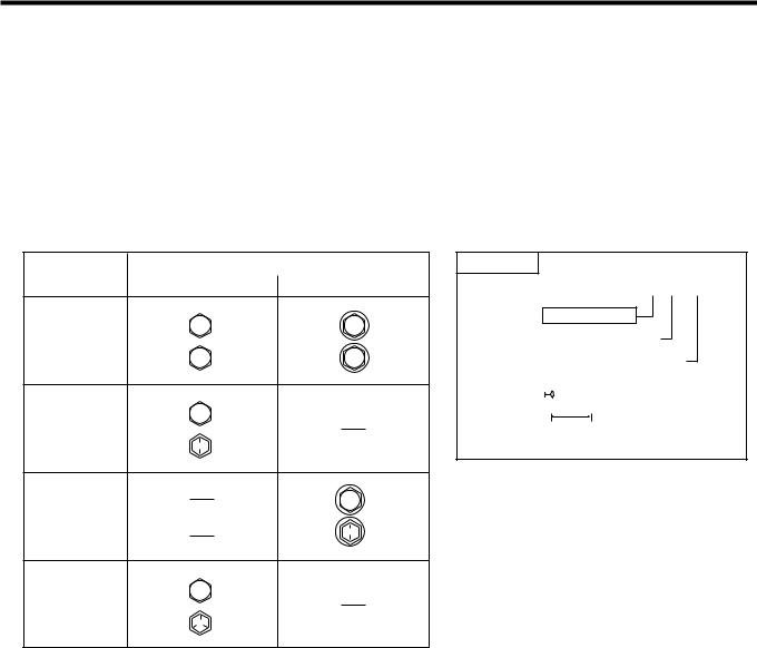
3-1-3 IDENTIFICATION
Identification of strength division by checking bolts themselves
Classification |
Shape of head (how to know strength division) |
|
(Strength division) |
Bolt without collar |
Bolt with collar |
|
4 |
4 |
4 |
T |
|
5
5 T
Identification by part number
Hexagonal bolt
Example of part number 9 1 1 1 1 ( 4 0 6 2 0
Strength division
Nominal diameter (mm)
Nominal length (mm)

 Nominal diameter
Nominal length
6
6 T
7
7 T
L11S5003ES20
|
|
|
|
|
|
|
|
|
A–6 |
3-1-4 TIGHTENING TORQUE TABLE FOR GENERAL STANDARD BOLTS |
|
|
|||||||
|
|
|
|
|
|
|
|
||
|
|
Strength division |
Nominal diameter |
Pitch |
Standard tightening torque (N;m{kgf;cm}) |
||||
|
|
(mm) |
(mm) |
Bolt without flange |
Bolt with flange |
||||
|
|
|
|
||||||
|
|
|
|
6 |
1 |
5.4 {55} |
5.9 {60} |
||
|
|
|
|
8 |
1.25 |
13 |
{130} |
14 |
{145} |
|
4 |
T |
10 |
1.25 |
25 |
{260} |
28 |
{290} |
|
|
12 |
1.25 |
47 |
{480} |
53 |
{540} |
|||
|
|
|
|
||||||
|
|
|
|
14 |
1.5 |
74 |
{760} |
83 |
{850} |
|
|
|
|
16 |
1.5 |
113 |
{1150} |
|
( |
|
|
|
|
6 |
1 |
6.4 {65} |
|
( |
|
|
|
|
|
8 |
1.25 |
16 |
{160} |
|
( |
|
5 |
T |
10 |
1.25 |
32 |
{330} |
|
( |
|
|
12 |
1.25 |
59 |
{600} |
|
( |
|||
|
|
|
|
|
|||||
|
|
|
|
14 |
1.5 |
91 |
{930} |
|
( |
|
|
|
|
16 |
1.5 |
137 |
{1400} |
|
( |
|
|
|
|
6 |
1 |
7.8 {80} |
8.8 {90} |
||
|
|
|
|
8 |
1.25 |
19 |
{195} |
20.5 {210} |
|
|
6 |
T |
10 |
1.25 |
39 |
{400} |
43 |
{440} |
|
|
|
|
|
12 |
1.25 |
72 |
{730} |
79 |
{810} |
|
|
|
|
14 |
1.5 |
109 |
{1100} |
123 |
{1250} |
|
|
|
|
6 |
1 |
11 |
{110} |
12 |
{120} |
|
|
|
|
8 |
1.25 |
25 |
{260} |
28 |
{290} |
|
7 |
T |
10 |
1.25 |
52 |
{530} |
58 |
{590} |
|
|
12 |
1.25 |
95 |
{970} |
103 |
{1050} |
|||
|
|
|
|
||||||
|
|
|
|
14 |
1.5 |
147 |
{1500} |
167 |
{1700} |
|
|
|
|
16 |
1.5 |
225 |
{2300} |
|
( |

A–7
3-1-5 WHEN AN EXTENSION TOOL IS USED
1.When tightening with the SST or a tool connected to the torque wrench for a drive-end extension, a higher tightening torque will result, if tightened until the reading on the torque wrench indicates the specified torque.
2.This manual contains specified torques only. When using the SST or an extension tool, the torque wrench reading must be computed using the following formula.
3.Calculation formula: T96T)B / (A'B)
Abbrevia- |
Meaning |
UNIT |
B |
tion code |
|
A |
|
|
|
|
|
T9 |
Torque wrench reading |
N;m{kgf;cm} |
|
T |
Specified tightening torque |
N;m{kgf;cm} |
|
A |
Length of the SST or a tool |
cm |
|
B |
Torque wrench length |
cm |
|
H11S5030T10

A–8
4 INSTRUCTIONS ON SERVICING OPERATIONS OF ENGINE AY
1.Prior to the disassembling, be sure to wash away sands and mud that have adhered to the external of the engine Ay so that they will not be admitted to the inside at the time of the disassembling and assembling.
2.When the joint section of light-alloy parts is to be disassembled, do not pry using a screwdriver or the like, but perform the disassembling by lightly tapping by means of a plastic hammer.
3.Place the disassembled parts in order at all times. Keep them away from dust. 4.Thoroughly wash each part before assembling. After drying, apply the designated oil. 5.Never wash aluminum and rubber parts with alkali chemicals.
6.Never wash rubber parts, such as O-rings and oil seals, with cleaning oil (white gasoline or the like). 7.Be sure to apply the designated oil to sliding surfaces and rotating surfaces before assembling them. 8.When a part is to be secured in a vise, be sure to secure it with aluminum sheets interposed.
9.Replace any snap ring that has been scratched or deformed with a new one.
10.Utmost care must be exercised so that the mating surface of the case will not be damaged, for the damaged mating surface will lead to oil leakage.
11.Prior to the application of seal agent, be sure to completely remove the oil seal agent remaining on the seal section. Then, wash the seal agent application section with white gasoline.
12.After the seal section has been assembled, wait for at least one hour, until the seal agent dries completely. Then, fill oil.
TO INDEX |
|
TO NEXT SECTION |

TO INDEX
A1 GENERAL INFORMATION |
A1 |
|
IMPORTANT SAFETY NOTICE------------ |
A1 - 1 |
GENERAL DESCRIPTION --------------- |
A1 - 1 |
WARNINGS, CAUTIONS AND |
|
NOTES ----------------------------------------- |
A1 - 1 |
GENERAL WARNINGS ------------------- |
A1 - 2 |
HOW TO USE THIS MANUAL ------------- |
A1 - 3 |
ARTICLES TO BE PREPARED --------- |
A1 - 3 |
REMOVAL AND INSTALLATION |
|
PROCEDURES ------------------------------ |
A1 - 3 |
DESCRIPTION OF SERVICE |
|
STANDARD VALUE ------------------------ |
A1 - 4 |
CONTENTS NOT DESCRIBED IN |
|
THIS MANUAL ------------------------------- |
A1 - 5 |
DEFINITIONS OF TERMS---------------- |
A1 - 5 |
ABBREVIATION CODES -------------------- |
A1 - 6 |
HOW TO GRASP SPECIFIED |
|
TIGHTENING TORQUE FOR |
|
GENERAL STANDARD BOLT AND |
|
NUT ------------------------------------------------ |
A1 - 7 |
DETERMINING PROCEDURE FOR |
|
TIGHTENING TORQUE FOR |
|
GENERAL STANDARD BOLTS AND |
|
NUTS ------------------------------------------- |
A1 - 7 |
UNIT ----------------------------------------------- |
A1 - 9 |
NEW UNIT BECAUSE OF THE |
|
INTRODUCTION OF THE SI UNIT ---- |
A1 - 9 |
PREFIX USED IN SI UNIT --------------- |
A1 - 9 |
GENERAL SERVICE INSTRUCTION--- |
A1 - 10 |
JACK UP OR LIFT UP ------------------- |
A1 - 10 |
INSTALLATION AND REMOVAL OF |
|
BATTERY TERMINAL-------------------- |
A1 - 10 |
CONNECTING/DISCONNECTING |
|
THE EARTH -------------------------------- |
A1 - 10 |
REPAIRING OF FUEL SYSTEM ------ |
A1 - 10 |
USE OF THE SST------------------------- |
A1 - 11 |
REMOVAL, DISASSEMBLY------------- |
A1 - 11 |
CHECK AND MEASUREMENT OF |
|
PARTS ---------------------------------------- |
A1 - 11 |
INSTALLATION, ASSEMBLING-------- |
A1 - 11 |
ADJUSTMENT, OPERATION |
|
CONFIRMATION--------------------------- |
A1 - 11 |
HANDLING OF HOSE OR THE LIKE A1 - 11 |
|
TOUCH UP ---------------------------------- |
A1 - 11 |
SUPPORTING POINTS FOR JACKS |
|
AND SAFETY STANDS--------------------- |
A1 - 12 |
SUPPORTING POINTS OF LIFTS ------ |
A1 - 14 |
TOWING INSTRUCTIONS----------------- |
A1 - 15 |
TOWING WITH ROPE (ONLY FOR |
|
EMERGENCY ) ---------------------------- |
A1 - 15 |
USING FLAT BED TRUCK-------------- |
A1 - 15 |
WHEEL LIFT TYPE ----------------------- |
A1 - 15 |
DIAGNOSTICS INSTRUCTIONS -------- |
A1 - 16 |
HOW TO PROCEED DIAGNOSIS---- |
A1 - 16 |
DATA LINK CONNECTOR ----------------- |
A1 - 19 |
ARRANGEMENT OF DLC |
|
TERMINAL --------------------------------- |
A1 - 19 |
HOW TO SHORT-CIRCUIT THE DLC A1 - 19 |
|
HOW TO SHORT-CIRCUIT USING |
|
THE SST. ------------------------------------ |
A1 - 20 |
HOW TO CONNECT WITH THE |
|
DIAGNOSIS TESTER(DS-21/DS-@)-- |
A1 - 20 |
INSTRUCTIONS FOR SYSTEM |
|
INSPECTION ---------------------------------- |
A1 - 21 |
HANDLING INSTRUCTION OF |
|
CONNECTOR ------------------------------ |
A1 - 21 |
CONNECTOR |
|
REMOVAL/INSTALLATION |
|
PROCEDURE ------------------------------ |
A1 - 21 |
CHECK PROCEDURE OF WIRE |
|
HARNESS AND CONNECTOR-------- |
A1 - 23 |
CIRCUIT INSPECTION OF |
|
COMPUTER UNIT ------------------------ |
A1 - 24 |
HANDLING INSTRUCTION OF |
|
SYSTEM ------------------------------------- |
A1 - 25 |
INSTRUCTIONS FOR RADIO |
|
INSTALLATION ------------------------------- |
A1 - 25 |
HANDLING INSTRUCTIONS ON |
|
CATALYTIC CONVERTER-EQUIPPED |
|
VEHICLES-------------------------------------- |
A1 - 25 |
PRECAUTION FOR VEHICLES |
|
EQUIPPED WITH SRS AIRBAG AND |
|
SEAT BELT PRETENSIONER ------------ |
A1 - 26 |
INSTRUCTIONS FOR SERVICE |
|
OPERATION -------------------------------- |
A1 - 26 |
VEHICLE IDENTIFICATION --------------- |
A1 - 31 |
BODY COLOR CODE-------------------- |
A1 - 31 |
VEHICLE IDENTIFICATION |
|
NUMBER ------------------------------------ |
A1 - 31 |
ENGINE TYPE AND ENGINE |
|
NUMBER ------------------------------------ |
A1 - 31 |
MANUFACTURER'S PLATE |
|
POSITION ----------------------------------- |
A1 - 32 |
CERTIFICATION REGULATION |
|
PLATE POSITION ------------------------- |
A1 - 33 |

A1–1
1 IMPORTANT SAFETY NOTICE
1-1 GENERAL DESCRIPTION
1.The vehicle is a machine comprising a great number of parts. Basically speaking, the vehicle is potentially hazard. However, one can handle it safely if he has the required knowledge.
2.Correct service methods and repair procedures are very vital for assuring not only the safety and reliability of a vehicle, but also the safety of service personnel concerned.
3.The methods and procedures contained in this manual describe in a general way the techniques which the manufacturer has recommended. Thus, they will contribute to ensuring the reliability of the products. The contents of the servicing operations come in a wide variety of ways. Moreover, techniques, tools and parts necessary for each operation are different widely from each other.
4.This manual does not cover all details of techniques, procedures, parts, tools and handling instructions which are necessary for these operations, for such coverage is impossible. Hence, any one who obtains this manual is expected first to make his responsible selection as to techniques, tools and parts which are necessary for servicing the vehicle concerned properly. Furthermore, he must assume responsibility for his actions in connection with his own safety.
5.Therefore, one should not perform any service if he is not capable of making responsible selection and/or if he can not understand the contents herein described, for this manual has been prepared for experienced service personnel.
1-2 WARNINGS, CAUTIONS AND NOTES
1.All these symbols have their specific purposes, respectively.
WARNING
•This symbol means that there is the possibility of personal injury of the operator himself or the nearby workers if the operator fails to follow the operating procedure prescribed in this manual.
CAUTION
•This symbol means that there is the possibility of damage to the component being repaired if the operator fails to follow the operating procedure prescribed in this manual.
NOTE
•To accomplish the operation in an efficient manner, additional instructions concerning the operation are given in this section.

A1–2
1-3 GENERAL WARNINGS
1-3-1 WARNING OVER THE WHOLE SERVICE OPERATIONS
1.Always wear safety glasses for eye protection.
2.Use safety stands whenever a procedure requires you to be under the vehicle.
3.Be sure that the ignition switch is always in the OFF position, unless otherwise required by the procedure.
4.Set the parking brake when working on the vehicle.
5.Operate the engine only in a well(ventilated area to avoid the danger of carbon monoxide.
6.Keep yourself and your clothing away from moving parts, when the engine is running, especially from the fan and belts.
7.To prevent serious burns, avoid contact with hot metal parts such as the radiator, exhaust manifold, tail pipe, catalytic converter and muffler.
8.Do not smoke while working on a vehicle.
9.To avoid injury, always remove rings, watches, loose hanging jewelry, and loose clothing before beginning to work on a vehicle.
10.Keep hands and other objects clear of the radiator fan blades! The electric cooling fan is mounted on the radiator and can start to operate anytime by a rise in coolant temperature or turning ON of the air conditioner switch in the case of vehicles equipped with an air conditioner. The electric cooling fan is also mounted on the condenser for air conditioner and starts to operate anytime when the air conditioner switch is turned ON. For this reason care should be taken to ensure that the electric cooling fan motor is completely disconnected when working under the hood.

A1–3
2 HOW TO USE THIS MANUAL
2-1 ARTICLES TO BE PREPARED
When SST, tool, measuring instrument, a sort of fat and oil to be prepared before operation are necessary, those are described by compiling in the table as preparation tools at the beginning of each item. However, the general tools, jacks, fixtures as considered being equipped always at the service shop are usually omitted.
2-2 REMOVAL AND INSTALLATION PROCEDURES
1.Block diagrams are posted so as to show the installed state of each part.
2.The application of a sort of fat and oil and sealer are instructed in the figure with arrow. And the indication of a tightening torque and non(reusable parts are also described. The explanation of each code is posted below the block diagram concerned.
3.The removal and installation (Disassembling and assembling) procedure list is shown just beneath of components figure.
The removal (Disassembling) procedure, the installation (Assembling) procedure and parts name are described in the sequence from left side of list. And the alphabet written before a part name links with alphabet in the figure.
4.In principle, reverse the removal (Or disassembly) procedure to install (Or assemble) the parts.
NOTE
•Only in cases where the installation (Or assembly) can not be carried out by reversing the removal (Or disassembly) procedure, the installation (Or assembly) procedure is provided.
5.In cases where a special procedure is required for the operation, a marking 8ji8 is provided in front of the removal (Or disassembly) procedure. Furthermore, explanation is given in the 8Main points of Removal (Disassembly)8 or the 8Main points of Installation (Assembly).8
The marking 8j8shows that there are the 8Main points of Removal (Disassembly),8 whereas 8i8 shows that there are the 8Main points of Installation (Assembly).8

A1–4
2-2-1 ENTRY EXAMPLE
(1) Components
g
T:46.6&2.4 {475&25}
|
|
f |
e |
|
|
|
|
|
|
|
c |
a |
m |
|
d |
|
|
||
|
|
|
|
|
|
~l |
|
T:36.8&2.4 {375&25}
b
~k 
j
~n
h
~i
W13C5006S24
k : Rubber grease
~: Non(reusable part Unit:N;m{kgf;cm}
(2) Disassembly and assembly procedures
1 |
a Cap, cylinder slide pin |
|
8 |
h |
Plate, disc brake pad guide |
2 |
b Pin, cylinder slide, No.1 |
|
9 |
i |
Boot, cylinder |
i 3 |
c Pad, disc brake, No.2 |
j |
10 |
j |
Piston, disc brake |
4 |
d Shim, anti squeal, No.1 |
|
11 |
k |
Seal, piston |
i 5 |
e Pad, disc brake w/ indicator. No.1 |
|
12 |
l |
Boot, pin |
6 |
f Shim, anti squeal, No.1 |
|
13 |
m Pin, cylinder slide, No.1 |
|
7 |
g Plate, disc brake pad guide |
|
14 |
n Bush, cylinder slide |
|
2-3 DESCRIPTION OF SERVICE STANDARD VALUE
The necessary service standard value for inspection and service operation are described with bold letter in the text as standard and allowable limit. The details of terms are described in the section for definition of terms.

A1–5
2-4 CONTENTS NOT DESCRIBED IN THIS MANUAL
The description of the next elemental operation may omit in this service manual, but please perform in an actual operation.
1.Jacking operation and lifting operation
2.Cleaning and cleansing of removed parts to perform at need 3.Visual inspection
2-5 DEFINITIONS OF TERMS
SPECIFIED |
This mark shows the standard value at the time of the check or adjustment. |
|
VALUE |
||
|
||
ALLOWABLE |
This mark shows the maximum or minimum value at the time of the check or adjustment. |
|
LIMIT |
||
|
||
DEVIATION |
This value refers to the difference between the maximum clearance and the minimum clearance. |
|
WARNING |
This symbol means that there is the possibility of personal injury of the operator himself or the nearby workers |
|
if the operator fails to follow the operating procedure prescribed in this manual. |
||
|
||
CAUTION |
This symbol means that there is the possibility of damage to the component being repaired if the operator |
|
fails to follow the operating procedure prescribed in this manual. |
||
|
||
|
Supplementary explanation which facilitates the operation is posted separately from the explanation. |
|
NOTE |
Because of difficulties in measurements to determine specified values, there may be cases where the speci- |
|
|
fied values for simple measurement methods are indicated if malfunctions are unlikely to take place actually. |

A1–6
3 ABBREVIATION CODES
The abbreviation codes that appear in this manual stand for the following, respectively.
ABBREVIATION CODE |
ORIGINAL WORD |
ABBREVIATION CODE |
ORIGINAL WORD |
|
|
|
|
|
|
2WD |
Two Wheel Drive |
LHD |
Left Hand Drive |
|
|
|
|
|
|
4WD |
Four Wheel Drive |
LIN |
Local Interconnect Network |
|
|
|
|
|
|
ABS |
Anti-lock Brake System |
LSPV |
Load Sensing Proportioning Valve |
|
|
|
|
|
|
ABV |
Air Bypass Valve |
LWR |
Lower |
|
|
|
|
|
|
A/C |
Air Conditioner |
MIL |
Malfunction Indicator Lamp |
|
|
|
|
|
|
ACC |
Accessory |
MP |
Multipurpose |
|
|
|
|
|
|
API |
American Petroleum Institute |
M/T |
Manual Transmission |
|
|
|
|
|
|
A/T |
Automatic Transmission |
N/A |
Natural Aspiration |
|
|
|
|
|
|
ATDC |
After Top Dead Center |
NOx |
Nitrogen Oxides |
|
|
|
|
|
|
ATF |
Automatic Transmission Fluid |
OPT |
Option |
|
|
|
|
|
|
Ay |
Assembly |
O/S |
Over Size |
|
|
|
|
|
|
BDC |
Bottom Dead Center |
PCV |
Positive Crankcase Ventilation |
|
|
|
|
|
|
BTDC |
Before Top Dead Center |
PR |
Ply Rating |
|
|
|
|
|
|
BVSV |
Bimetal Vacuum Switching Valve |
PTO |
Power Take Off |
|
|
|
|
|
|
CAN |
Controller Area Network |
RH |
Right Hand |
|
|
|
|
|
|
CD |
Compact Disc |
RHD |
Right Hand Drive |
|
|
|
|
|
|
CO |
Carbon Monoxide |
RR |
Rear |
|
|
|
|
|
|
DLC |
Data Link Connector |
S/A |
Sub-Assembly |
|
|
|
|
|
|
DLI |
Distributor Less Ignition |
SAE |
Society of Automotive Engineers |
|
|
|
|
|
|
DTC |
Diagnostic Trouble Code |
SRS |
Supplemental Restraint System |
|
|
|
|
|
|
DVVT |
Dynamic Variable Valve Timing |
SST |
Special Service Tool |
|
|
|
|
|
|
EBD |
Electronic Brake force Distribution |
STD |
Standard |
|
|
|
|
|
|
ECU |
Electronic Control Unit |
SW |
Switch |
|
|
|
|
|
|
EFI |
Electronic Fuel Injection |
T |
Torque |
|
|
|
|
|
|
EGR |
Exhaust Gas Recirculation System |
T/C |
Turbocharger |
|
|
|
|
|
|
EPS |
Electronic controlled Power Steering |
TDC |
Top Dead Center |
|
|
|
|
|
|
ESA |
Electronic Spark Advance |
UPR |
Upper |
|
|
|
|
|
|
EX |
Exhaust |
U/S |
Under Size |
|
|
|
|
|
|
F/L |
Fusible Link |
VCV |
Vacuum Control Valve |
|
|
|
|
|
|
FR |
Front |
VSV |
Vacuum Switching Valve |
|
|
|
|
|
|
GND |
Ground |
VTV |
Vacuum Transmitting Valve |
|
|
|
|
|
|
HC |
Hydro Carbon |
W/ |
With |
|
|
|
|
|
|
IG |
Ignition |
WVTA |
Whole Vehicle Type Approval |
|
|
|
|
|
|
IN |
Intake |
B |
Bolt |
|
|
|
|
|
|
ISC |
Idle Speed Control |
S |
Screw |
|
|
|
|
|
|
ISO |
International Organization for Stan- |
N |
Nut |
|
dardization |
||||
|
|
|
||
LCD |
Liquid Crystal Display |
W |
Washer |
|
|
|
|
|
|
LED |
Light Emitting Diode |
C |
Clip |
|
|
|
|
|
|
LH |
Left Hand |
|
|
|
|
|
|
|
A1–7
4 HOW TO GRASP SPECIFIED TIGHTENING TORQUE FOR GENERAL STANDARD BOLT AND NUT
4-1 DETERMINING PROCEDURE FOR TIGHTENING TORQUE FOR GENERAL STANDARD BOLTS AND NUTS
4-1-1 DETERMINING PROCEDURE FOR TIGHTENING TORQUE FOR BOLTS
Determine the strength division of bolts, based on the table below. Then, obtain the value, based on the tightening torque table.
4-1-2 DETERMINING PROCEDURE FOR TIGHTENING TORQUE FOR NUTS
Determine with the aforesaid method, based on the mating bolt.
4-1-3 IDENTIFICATION
Identification of strength division by checking bolts themselves
Classification |
Shape of head (how to know strength division) |
|
(Strength division) |
Bolt without collar |
Bolt with collar |
|
4 |
4 |
4T
5
5T
Identification by part number
Hexagonal bolt
Example of part number 9 1 1 1 1 ( 4 0 6 2 0
Strength division
Nominal diameter (mm)
Nominal length (mm)

 Nominal diameter
Nominal length
6
6T
7
7T
L11S5003ES20

A1–8
4-1-4 TIGHTENING TORQUE TABLE FOR GENERAL STANDARD BOLTS
Strength divisin |
Nominal diameter |
Pitch |
Standard tightening torque (N;m{kgf;cm}) |
||||
(mm) |
(mm) |
Bolt without collar |
Bolt with collar |
||||
|
|||||||
|
6 |
1.0 |
5.4 {55} |
5.9 {60} |
|||
|
8 |
1.25 |
13 |
{130} |
14 |
{145} |
|
4 T |
10 |
1.25 |
25 |
{260} |
28 |
{290} |
|
12 |
1.25 |
47 |
{480} |
53 |
{540} |
||
|
|||||||
|
14 |
1.5 |
74 |
{760} |
83 |
{850} |
|
|
16 |
1.5 |
113 |
{1150} |
|
( |
|
|
6 |
1.0 |
6.4 {65} |
|
( |
||
|
8 |
1.25 |
16 |
{160} |
|
( |
|
5 T |
10 |
1.25 |
32 |
{330} |
|
( |
|
12 |
1.25 |
59 |
{600} |
|
( |
||
|
|
||||||
|
14 |
1.5 |
91 |
{930} |
|
( |
|
|
16 |
1.5 |
137 |
{1400} |
|
( |
|
|
6 |
1.0 |
7.8 {80} |
8.8 {90} |
|||
|
8 |
1.25 |
19 |
{195} |
20.5 {210} |
||
6 T |
10 |
1.25 |
39 |
{400} |
43 |
{440} |
|
|
12 |
1.25 |
72 |
{730} |
79 |
{810} |
|
|
14 |
1.5 |
109 |
{1100} |
123 |
{1250} |
|
|
6 |
1.0 |
11 |
{110} |
12 |
{120} |
|
|
8 |
1.25 |
25 |
{260} |
28 |
{290} |
|
7 T |
10 |
1.25 |
52 |
{530} |
58 |
{590} |
|
12 |
1.25 |
95 |
{970} |
103 |
{1050} |
||
|
|||||||
|
14 |
1.5 |
147 |
{1500} |
167 |
{1700} |
|
|
16 |
1.5 |
225 |
{2300} |
|
( |
|
4-1-5 WHEN AN EXTENSION TOOL IS USED
1.When tightening with the SST or a tool connected to the torque wrench for a drive-end extension, a higher tightening torque will result, if tightened until the reading on the torque wrench indicates the specified torque.
2.This manual contains specified torques only. When using the SST or an extension tool, the torque wrench reading must be computed using the following formula.
3.Calculation formula: T96T)B / (A'B)
Codes |
Meaning |
Unit |
A |
B |
|
T9 |
Torque wrench reading |
N;m{kgf;cm} |
|||
|
|
||||
T |
Specified tightening torque |
N;m{kgf;cm} |
|
|
|
A |
Length of the SST or a tool |
cm |
|
|
|
B |
Torque wrench length |
cm |
|
|
H11S5030T10

A1–9
5 UNIT
As for the units, the SI units (International unit system) have been posted. (The hitherto(employed units, too, are posted.)
Example: 33.25&13.25N;m{340&135kgf;cm}
5-1 NEW UNIT BECAUSE OF THE INTRODUCTION OF THE SI UNIT
1.SI unit is the international unit system established by aiming to proceed the communication in technology smoothly by unifying the former unit system which were different internationally each other into one value by one unit. The specification value is described in accordance with SI unit system in this service manual.
ITEM |
SI unit |
Conventional units |
Conversion table |
|
Force |
N |
kgf |
1kgf 6 9.80665 N |
|
Torque |
N;m |
kgf;cm |
1kgf;cm 6 0.0980665 N;m |
|
Pressure |
kPa |
kgf/cm2 |
1kgf/ cm2 6 98.0665 kPa |
|
mmHg |
1mmHg 6 0.133322 kPa |
|||
|
|
|||
Spring constant |
N/mm |
kgf/mm |
1kgf/mm 6 9.80665 N/mm |
|
Volume |
% |
cc |
1000cc 6 1% |
|
Power |
kW |
PS |
1PS 6 0.735499 kW |
5-2 PREFIX USED IN SI UNIT
The following are typical prefixes used in SI Unit (10 to the power of n).
M (mega) |
106 |
k (kilo) |
103 |
h (hecto) |
102 |
da (deca) |
101 |
d (deci) |
10(160.1 |
c (centi) |
10(260.01 |
m (milli) |
10(360.001 |
µ (micro) |
10(660.000001 |
A1–10
6 GENERAL SERVICE INSTRUCTION
6-1 JACK UP OR LIFT UP
1.When only front section or rear section of a vehicle is jacked up, be sure to place chocks at the wheels so as to insure safe operations
2.When the vehicle has been jacked up, be sure to support the vehicle at the specified section using the safety stands.
3.When the vehicle has been lifted up, be sure to set the cradle of the lift at the specified location, and lift it up. And after the jacking up, ensure to apply the protective safety device.
And after the jacking up, ensure to apply the protective safety device.
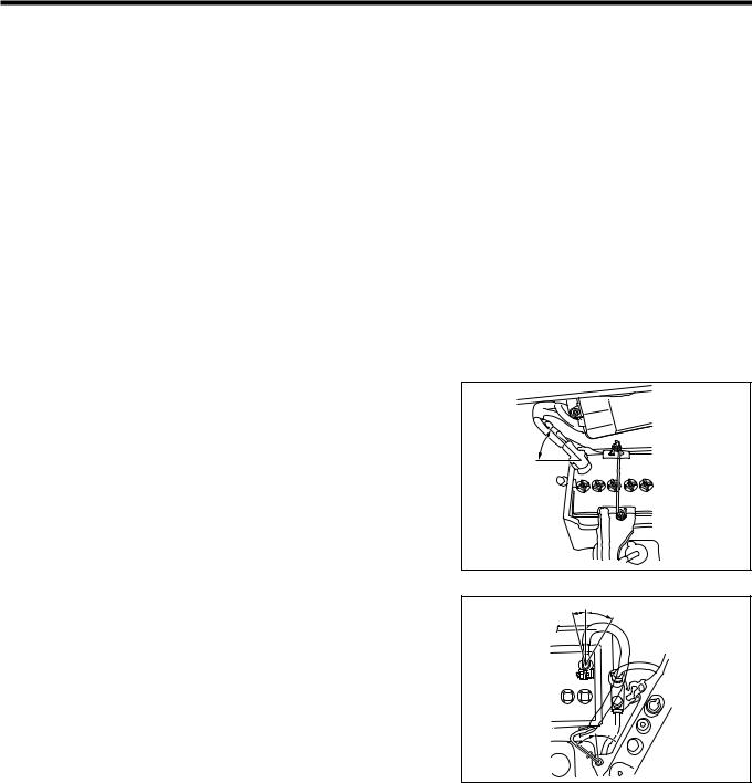
6-2 INSTALLATION AND REMOVAL OF BATTERY TERMINAL
1.Disconnect the battery negative (-) terminal prior to repairing the electrical system, mounting/dismounting the engine, etc.
2.When connecting/disconnecting the battery terminal, turn the IG switch to OFF (LOCK position), and loosen the terminal nut completely. Do not pry the battery terminal off.
3.When the battery terminal is removed, clock, radio setup and the memory of diagnosis will be erased.Record the contents of the memory before disconnecting the battery terminal so that it can be restored as required after the work is complete.
4.When connecting the battery terminal, connect the posi- |
|
|
tive (+) terminal first so that that the terminal wire will be |
|
|
placed in the marked area of the illustration, and tighten |
40$ |
|
to the specified torque. |
||
|
||
TIGHTENING TORQUE: 6.35&1.45N;m |
|
|
{65&15kgf;cm} |
|
T11H7302T10
5.When connecting the battery negative (-) terminal, con- |
15$ 30$ |
nect the terminal so that that the terminal wire will be |
|
placed in the marked area of the illustration, and tighten |
|
to the specified torque. |
|
TIGHTENING TORQUE: 6.35&1.45N;m |
|
{65&15kgf;cm} |
|
6.Securely install the cover, etc. on the terminal after work is |
45$ |
|
|
complete. |
|
T11H7303T10
6-3 CONNECTING/DISCONNECTING THE EARTH
1.When the earth was removed, check that the earth is securely in place and then turn ON the IG switch.
6-4 REPAIRING OF FUEL SYSTEM
1.Do not work near open flames.
2.Be certain to place a suitable container, a cloth, etc. under the connected section of the fuel line before disconnecting the fuel line.
3.Before the fuel line is disconnected, be sure to release the inner pressure of the fuel tank by detaching the fuel filler cap.
4.Be sure to prevent the fuel from splashing with a cloth or the like, when the union bolt or other connected section of the fuel line is loosened or slackened.
5.Tighten each connecting section to the specified torque. 6.Attach the specified clips to each connecting section.

A1–11
6-5 USE OF THE SST
1.Utilize the SST (Special tool) effectively in order to improve efficiency and accuracy of work operation.
6-6 REMOVAL, DISASSEMBLY
1.In case for the operation at the complicate place, the stamping and mating mark shall be put at the place where there is no influence to the function, so that the assembling operation becomes easy.
2.At every time when each parts are removed, check the condition when it was assembled , deformation, breakage, roughness and existence of scratch .
3.Arrange the removed parts in order, and divide them to the parts to replace and parts to reuse . 4.Each parts to be reused shall be performed enough cleaning and cleansing operation.
6-7 CHECK AND MEASUREMENT OF PARTS
1.As regards those parts to be used again, perform thorough checks and measurements, as required.
6-8 INSTALLATION, ASSEMBLING
1.Assemble the good parts with correct procedure following the specified standard (Value for the adjusting , tightening torque).
2.Use the genuine parts when replace the parts.
3.Ensure to apply the seal packing and grease by a place. 4.Ensure to use new packing, gasket or the like, cotter pin etc.
5.When use the seal bolt, apply the specified liquid gasket and seal lock agent on.
6.As for bolts and nuts, use the specified ones. Unless otherwise specified, the side for which the torque is indicated should be tightened to the specified torque, using a torque wrench. If there is no means to prevent the turning at the opposite side, be sure to prevent turning with box wrenches, spanners or the like.
6-9 ADJUSTMENT, OPERATION CONFIRMATION
1.Adjust with the specified service standard value by using |
|
|
the gauge and the tester. |
To be settled |
|
6-10 HANDLING OF HOSE OR THE LIKE |
|
|
1.Check the plug depth and clamp position before removing |
|
|
the hose. |
|
|
2.When re-using the hose, install the clamps so that they |
|
|
match the clamp marks remaining on the hose. |
|
|
CAUTION |
Clamp mark |
|
• Replace the clamps if they are deformed or flattened. |
||
|
||
• Replace the hose a new one if the hose has a loose |
H11S5031ET10 |
|
|
||
fitting with the joint. |
|
|
3.Ensure that the spring type clamp is properly seated after |
|
|
installation. |
|
|
4.Ensure to insert the fuel hose, water hose or the like with- |
|
|
out coming out or leakage. |
|
|
5.Be careful that fuel shall not splash on the parts near by |
|
|
when remove the fuel hose. (Deep care shall be paid for |
|
|
engine mount rubber or the like, as there may be possi- |
|
|
bility to get material deterioration for liquid of gasoline |
|
|
series.) |
|
|
6-11 TOUCH UP |
|
1.When removed the bolt or the like during body fitting operation and others, the scratch of the paint finishing surface on the body and bolt shall be repaired by the body color.

A1–12
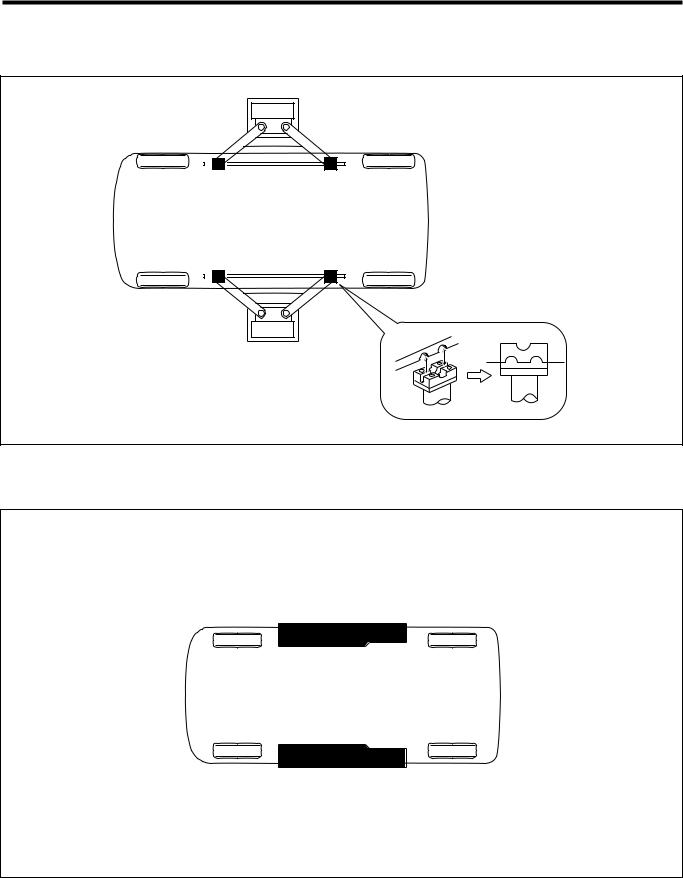
7 SUPPORTING POINTS FOR JACKS AND SAFETY STANDS
PJack supporting point
Front side: Front suspension member center protruding section Rear side: Rear floor cross member center section
CAUTION
•Do not jack up the rear suspension center beam portion.
Deformation and/or damage to the beam might cause controllability problems.
Engine
T11S5506ES30

A1–13
PRigid rack supporting points
Support 4 locations, namely front, rear, right and left as shown in the illustration below.
CAUTION
•The spot welded reinforcement plate provides adequate strength to the supporting points. Therefore, do not support the vehicle at points other than these supporting points.
T11S5007S38
A1–14
8 SUPPORTING POINTS OF LIFTS
PSwing Arm Type
Match the lift supports with the rigid rack supporting points.
H11S5008S20
PPlate type
Drive the vehicle onto the center of the right and left supports.
Since the front part is heavier, lift up the vehicle at the front wherever possible.
H11S5009S20
A1–15
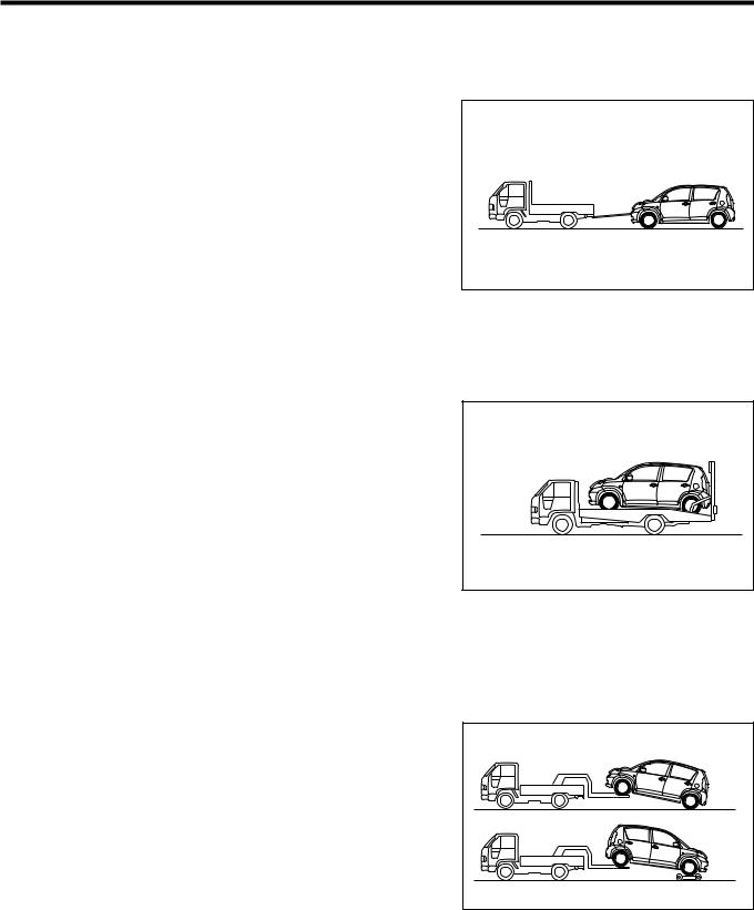
9 TOWING INSTRUCTIONS
1.Be certain to transfer the vehicle by using the flat deck truck when the running system and/or driving
system seems to be abnormal.
2.Do not tow with the rope for an automatic transmission vehicle.
9-1 TOWING WITH ROPE (ONLY FOR EMERGENCY )
Release parking brake, and turn IG switch to ACC position, and then put the shift lever into neutral range.
CAUTION
•Do not tow with the rope for an automatic transmission vehicle.
•Do not tow with the rope when the running system and/or driving system seems to be abnormal.
•When drive with engine stopping, brake efficiency become less due to no functioning of the brake servo system. Depress the brake pedal more powerfully than
the usual.
9-2 USING FLAT BED TRUCK
1.Transfer the vehicle with applying parking brake and fixing the vehicle firmly.
Towing by means of a rope
T11S5016ET10
Transport on a track
T11S5017ET10
9-3 WHEEL LIFT TYPE
CAUTION
• Do not allow anyone to be in the vehicle being towed.
9-3-1 TO TOW WITH REAR WHEELS ON GROUND
1.Release the parking brake.
9-3-2 TO TOW WITH FRONT WHEELS ON GROUND
1.Use a towing dolly.
2.If a towing dolly is not available, and turn IG switch to ACC position, and then put the shift lever into neutral range (For manual transmission vehicle).
CAUTION
•For an automatic transmission vehicle, be sure to always use a towing dolly.
Wheel lift type
T11S5518ET10
A1–16
10 DIAGNOSTICS INSTRUCTIONS
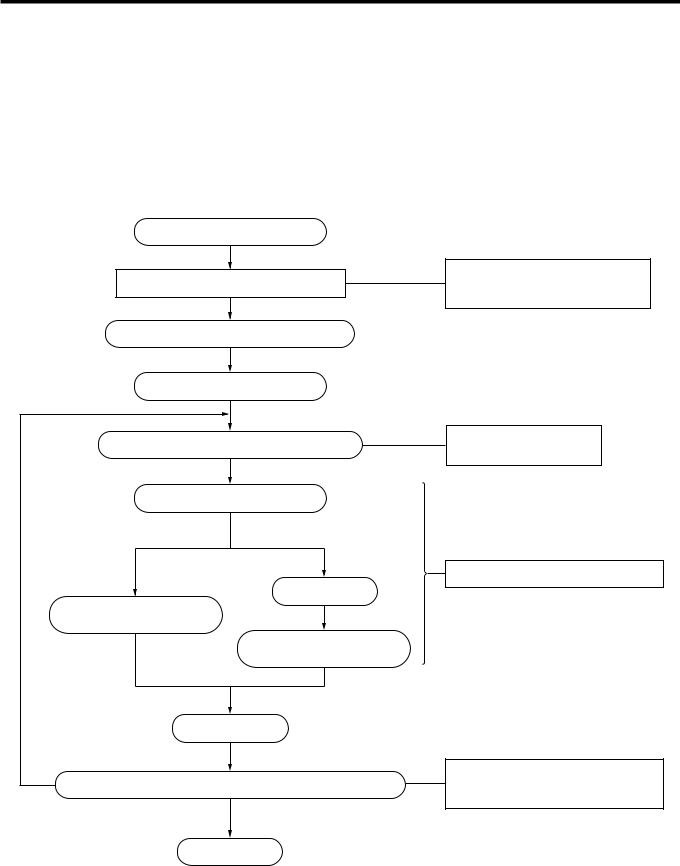
10-1 HOW TO PROCEED DIAGNOSIS
1.Each electronic control system equipped on the vehicle is an important clue at performing trouble shooting. Also this system has self(diagnosis function to inspect the malfunction portion which occurred in corresponding system, and battery back up (The function that power source for diagnosis code memory is supplied even if IG switch is OFF) is equipped for self(diagnosis function of electronic control system with, and is designed so that diagnosis code is memorized to each system. As the function of diagnosis code memory is different by each system, perform the confirmation / elimination of code memory according to the right operation procedure after confirming equipped diagnosis code memory function.
Entry of malfunctioning vehicle
Diagnosis through question-and-answer
Confirmation and record of diagnosis code
Erasure of diagnosis code
Reconfirmation of malfunctioning phenomenon
Reconfirmation of diagnosis code
Abnormal code |
Normal code |
|
Basic check |
Trouble-shooting according |
|
to diagnosis code |
|
|
Trouble-shooting according |
|
malfunctioning phenomenon |
Ask the customer concerning
the conditions and the environment when malfunction occurred.
Confirm phenomenon and grasp problem conditions.
Narrow down malfunctioning systems.
Repair or replace
NO
Confirmation test (Has vehicle resumed its normal operation?)
YES
End
Confirm that the malfunctioning phenomenon that customer spoke about has been remedied completely.
L11E7008ES35
 Loading...