


DAIHATSU
J100
SECTION INDEX
SECTION NAME |
SECTION |
|
|
GENERAL INFORMATION |
GI |
|
|
||
|
MA |
|
MAINTENANCE |
||
|
||
|
EM |
|
ENGINE MECHANICAL |
||
|
||
|
EC |
|
EMISSION CONTROL |
||
|
||
|
EF |
|
EFI SYSTEM |
||
|
||
|
LU |
|
LUBRICATION SYSTEM |
||
|
||
|
CO |
|
COOLING SYSTEM |
||
|
||
|
IG |
|
IGNITION SYSTEM |
||
|
||
|
ST |
|
STARTING SYSTEM |
||
|
||
|
CH |
|
CHARGING SYSTEM |
||
|
||
|
CL |
|
CLUTCH |
||
|
||
|
MT |
|
MANUAL TRANSMISSION |
||
|
||
|
AT |
|
AUTOMATIC TRANSMISSION |
||
|
||
|
TR |
|
TRANSMISSION & TRANSFER |
||
|
||
|
PR |
|
PROPELLER SHAFT |
||
|
||
|
DF |
|
FRONT & REAR DIFFERENTIAL |
||
|
||
|
FS |
|
FRONT AXLE & SUSPENSION |
||
|
||
|
RS |
|
REAR AXLE & SUSPENSION |
||
|
||
|
BR |
|
BRAKE (Including A.B.S) |
||
|
||
|
SR |
|
STEERING |
||
|
||
|
BO |
|
BODY |
||
|
||
|
BE |
|
Including Airbag system |
||
BODY ELECTRICAL (and immobilizer system) |
||
|
HW |
|
HARNESS & WIRING DIAGRAM |
||
|
Downloaded from www.Manualslib.com manuals search engine

SERVICE MANUAL
DAIHATSU
J100
FOREWORD
This service manual describes the maintenance and servicing procedures for the Model J100.
Applicable Model: J100
In this service manual, the entire portion is divided into 23 sections. Each section has an index along with a table of contents at the beginning. For easier reference, the upper part of each page bears the section title concerned.
All information used in this service manual was in effect at the time when the manual was printed. However, the specifications and procedures may be revised due to continuing improvements in the design without advance notice and without incurring any obligation to us.
Published in June, 1997
NO. 9710-JE
DAIHATSU MOTOR
©1997 DAIHATSU MOTOR CO., LTD.
All rights reserved. This material may not be repr out the written permission of Overseas Service
Downloaded from www.Manualslib.com manuals search engine

DAIHATSU
GI
J100
GENERAL INFORMATION
IMPORTANT SAFETY NOTICE .................... |
GI– 2 |
WARNINGS, CAUTIONS AND NOTES..... |
GI– 2 |
HOW TO USE THIS MANUAL ...................... |
GI– 4 |
CONTENTS OF EXPLANATION .............. |
GI– 4 |
ABBREVIATION CODES ............................. |
GI– 6 |
GENERAL SERVICE INSTRUCTION .......... |
GI– 7 |
HANDLING INSTRUCTIONS ON |
|
CATALYTIC CONVERTER ......................... |
GI– 8 |
JACKING POINTS AND SUPPORTING |
|
POINTS OF SAFETY STANDS ................. |
GI– 9 |
MODEL VARIATION ..................................... |
GI–13 |
CHASSIS SERIAL NUMBER STAMPED |
|
POSITION ..................................................... |
GI–14 |
MANUFACTURER’S PLATE POSITION ....... |
GI–14 |
CONTENTS OF MANUFACTURER’S |
|
PLATE....................................................... |
GI–14 |
ENGINE NUMBER AND ENGINE TYPE |
|
STAMPED POSITIONS............................... |
GI–15 |
BODY COLOR INFORMATION ...................... |
GI–15 |
COLOR CODE IN THE WORLD ................ |
GI–16 |
TRIM CODE .................................................... |
GI–16 |
|
JGI00001-00000 |
NO. 9710-JE
Downloaded from www.Manualslib.com manuals search engine

GI–2
IMPORTANT SAFETY NOTICE
The vehicle is a machine comprising a great number of parts. Basically speaking, the vehicle is potentially hazard. However, one can handle it safely if he has the required knowledge.
Correct service methods and repair procedures are very vital for assuring not only the safety and reliability of a vehicle, but also the safety of service personnel concerned.
The methods and procedures contained in this manual describe in a general way the techniques which the manufacturer has recommended. Thus, they will contribute to ensuring the reliability of the products. The contents of the servicing operations come in a wide variety of ways. Moreover, techniques, tools and parts necessary for each operation are different widely from each other.
This manual does not cover all details of techniques, procedures, parts, tools and handling instructions which are necessary for these operations, for such coverage is impossible. Hence, any one who obtains this manual is expected first to make his responsible selection as to techniques, tools and parts which are necessary for servicing the vehicle concerned properly. Furthermore, he must assume responsibility for his actions in connection with his own safety.
Therefore, one should not perform any service if he is not capable of making responsible selection and/or if he can not understand the contents herein described, for this manual has been prepared for experienced service personnel.
WARNINGS, CAUTIONS AND NOTES
All these symbols have their specific purposes, respectively.
WARNING:
•This symbol means that there is the possibility of personal injury of the operator himself or the nearby workers if the operator fails to follow the operating procedure prescribed in this manual.
CAUTION:
•This symbol means that there is the possibility of damage to the component being repaired if the operator fails to follow the operating procedure prescribed in this manual.
NOTE:
•To accomplish the operation in an efficient manner, additional instructions concerning the operation are given in this section.
The following list describes general WARNINGS:
•Always wear safety glasses for eye protection.
•Use safety stands whenever a procedure requires you to be under the vehicle.
•Be sure that the ignition switch is always in the OFF position, unless otherwise required by the procedure.
•Set the parking brake when working on the vehicle.
•Operate the engine only in a well-ventilated area to avoid the danger of carbon monoxide.
•Keep yourself and your clothing away from moving parts, when the engine is running, especially from the fan and belts.
•To prevent serious burns, avoid contact with hot metal parts, such as the radiator, exhaust manifold, tail pipe, catalytic converter and muffler.
•Do not smoke while working on a vehicle.
•To avoid injury, always remove rings, watches, loose hanging jewelry, and loose clothing before beginning to work on a vehicle.
•Keep hands and other objects clear of the radiator fan blades! The electric cooling fan is mounted on the radiator and can start to operate at anytime by a rise in coolant temperature or turning ON of the air conditioner switch in the case of vehicles equipped with an air conditioner. The electric cooling fan is also mounted on the condenser for air conditioner and starts to operate anytime when the air conditioner switch is turned “ON”. For this reason care should be taken to ensure that the electric cooling fan motor is completely disconnected when working under the hood.
Downloaded from www.Manualslib.com manuals search engine

GI–3
The UNITS used in this manual are showed as the SI UNIT (International System of Unit), and alternatively showed in the metric system.
“Example”
24.5 - 34.3 N·m (2.5 - 3.5 kgf-m)
JGI00002-00000
Downloaded from www.Manualslib.com manuals search engine
GI–4
HOW TO USE THIS MANUAL
CONTENTS OF EXPLANATION
1.Schematic Diagram of Components
(1)The schematic diagram of components that appears at the beginning of each section describes the nomenclature and installed conditions of each component. Furthermore the tightening torque is posted in the figure.
(2)Those parts whose reuse is not permitted bear a “ ” mark for an identification purpose. Be certain to replace these parts with new ones during the assembly.
(3)During the assembly, be sure to apply grease to those parts indicated by the mark in the figure.
(Example)
T : 11.80 - 17.7 (1.2 - 1.8)
q Brake master cylinder Ay w Reservoir tank fill cap
e Reservoir tank cap spacer r Reservoir tank diaphragm t Switch operating float
y Master cylinder reservoir tank S/A u Clamp
i Set bolt o Gasket !0Gasket
!1Master cylinder repair kit
JGI00003-00001
2.Servicing Procedure
(1)In principle, the servicing procedure is described in the following sequence given below: Removal → Inspection → Installation, and Disassembly → Inspection → Assembly.
(2)The explanation covers detailed servicing methods, specifications and notes.
(3)The main point of each item explains the servicing section and servicing procedure, using illustrations.
(Example)
What to do |
How to do it |
3.Brake tube installation
(1)Install the brake tube to the wheel cylinder temporarily by hands.
(2)Tighten the brake tube to the wheel cylinder, using the following SST.
SST: 09751-36011-000
What to do and where
09751-36011-000
JGI00004-00002
Downloaded from www.Manualslib.com manuals search engine

GI–5
(4)The inspection in this manual describes only checking operation. Therefore, if you find any malfunction, replace any defective parts with new ones.
3.SST
For those operations which require the use of any SST, the SST numbers concerned are given in bold letters.
4.Service Specifications
Service specifications are indicated in bold letters or enclosed by heavy lines. Be certain to confirm the specifications concerned.
5.Tightening Torque
For those operations which require the control of tightening torque, the relevant tightening torque is given in bold letters. Be certain to confirm the tightening torque concerned.
6.Definitions of Terms
Specified Value …… A value which represents the allowable range during the inspection and adjustment.
Limit ………………… A maximum or a minimum limit which the value should not exceed or fall below.
JGI00005-00000
Downloaded from www.Manualslib.com manuals search engine

GI–6
ABBREVIATION CODES
The abbreviation codes that appear in this workshop manual stand for the following, respectively.
Abbreviation code |
Original word |
Meaning |
|
|
|
|
|
A/C |
Air Conditioner |
Refers to air conditioner. |
|
|
|
|
|
A/T, AT |
Automatic Transmission |
Refers to automatic transmission |
|
|
|
|
|
A/Y or Ay |
Assembly |
Refers to an assembled component comprising more than two single parts or sub-assembly |
|
|
|
parts. |
|
|
|
|
|
API |
American Petroleum |
The standards set forth by the American Petroleum Institute (abbreviated as API |
|
|
Institute |
Classification) have been employed to evaluate and classify properties of various oils. |
|
|
|
Engine oils for gasoline engines are classified as SD, SE, SF and so on, whereas engine oils |
|
|
|
for diesel engines are classified as CC, CD and so on. |
|
|
|
|
|
ECU |
Electronic Control Unit |
Refers to electronic control unit. |
|
|
|
|
|
EFI |
Electronic |
Refers to electronic fuel injection. |
|
Fuel Injection |
|||
|
|||
|
|
|
|
F/L |
Fusible Link |
Refers to fusible link. |
|
|
|
|
|
L.H.D. |
Left-Hand Drive |
Left-hand drive vehicle. |
|
|
|
|
|
LH |
Left Hand |
Refers to left side. |
|
|
|
|
|
M/T, MT |
Manual Transmission |
Refers to manual transmission. |
|
|
|
|
|
MP |
Multipurpose |
Means that the following item has multi-purposes. |
|
|
|
|
|
O/S |
Oversize |
In instances where fitting becomes too loose due to wear resulting from use for a long period |
|
|
|
of time or due to frequent removal/installation operations, if the fitting part (e.g. piston) is |
|
|
|
replaced with a part having larger dimensions, the other mating part may be put into use |
|
|
|
again. “Oversized” parts denote those parts having larger dimensions compared with the |
|
|
|
standard parts. |
|
PR |
Ply Rating |
Represents strength of tires. |
|
|
|
The larger the ply rating number, the stronger the tire strength. |
|
|
|
|
|
R.H.D. |
Right-Hand Drive |
Right hand drive vehicle |
|
|
|
|
|
RH |
Right Hand |
Refers to right side. |
|
|
|
|
|
S/A |
Sub-Assembly |
Refers to a component comprising more than two single parts which are welded, staked, or |
|
|
|
studded to each other to form a single component. |
|
|
|
|
|
SAE |
Society of Automotive |
For example, automotive oils are designated as SAE so and so number. |
|
|
Engineers |
These designation numbers have been set forth by the Society of Automotive Engineers in the |
|
|
|
United States of America (SAE). The larger the SAE number, the higher the oil viscosity. |
|
|
|
Conversely, the smaller the SAE number, the lower the oil viscosity. |
|
SST |
Special Service Tool |
Refers to a tool designed for a specific purpose. |
|
|
|
|
|
STD |
Standard |
When referring to automotive parts, “standard” represents those parts which have been |
|
|
|
installed originally by the manufacturer and which have standard dimensions. |
|
|
|
|
|
T |
Torque |
Refers to tightening torque. |
|
|
|
|
|
U/S |
Under Size |
In the same manner as with the “oversized” parts, if fitting part (e.g. bush and bearing) is |
|
|
|
replaced with a part having smaller bore dimensions, the other mating part may be put into |
|
|
|
use again. “Under sized” parts denote those parts having smaller dimensions compared with |
|
|
|
standard parts. |
|
VSV |
Vacuum Switching |
Refers to vacuum switching valve. |
|
|
Valve |
||
|
|
||
|
|
|
|
W/ |
With |
Denotes that the following part is attached. |
|
|
|
|
|
ETR |
Electronic Tuning |
Radio which incorporates variable capacitance, etc. which varies the value according to an |
|
|
Radio |
applied voltage or current. |
|
|
|
|
|
|
|
JGI00006-00000 |
The abbreviation codes that appear in the figure stand for the following, respectively.
B |
Bolt |
|
S |
Screw |
|
|
|
|
|
N |
Nut |
|
W |
Washer |
|
|
|
|
|
JGI00007-00000
Downloaded from www.Manualslib.com manuals search engine

GI–7
GENERAL SERVICE INSTRUCTION
1.Use fender covers, seat covers and floor sheets so that the vehicle may not get dirty or be scratched.
2.Jacking up
(1)When only the front section or rear section of the vehicle is jacked up, be sure to place chocks at the wheels so as to insure safe operations.
(2)When the vehicle has been jacked up, be sure to support the vehicle at the specified section using safety stands. (See page GI–9)
3.Handling instructions related to battery.
(1)Before you start performing the electrical works, make certain to disconnect the battery ground cable terminal from the negative (–) terminal of the battery.
NOTE:
•Before disconnecting the battery ground cable terminal from the negative (–) terminal of the battery, be sure to read out the diagnosis code of the EFI, Airbag and immobilizer system etc., if the vehicle is equipped with such systems, when necessary.
•After reconnecting the battery ground cable terminal to the negative terminal of the battery, be sure to reset the watch or radio, if the vehicle is equipped with such equipment.
(2)When it becomes necessary to disconnect the battery power supply for the purpose of carrying out checks or repairs, always disconnect the battery ground cable terminal from the negative terminal of the battery first.
(3)To avoid damaging battery plates, after the terminal nut has been loosened, pull out the battery ground cable terminal straight upward, rather than turning or prying the terminal.
NOTE:
•Be sure to employ a battery terminal puller (commercially available) to remove the battery ground cable terminal from the negative terminal of the battery, if encountered any difficulty.
(4)Clean the battery terminal posts or battery ground terminals, using a cloth. Never use a file or other adhesive agents.
(5)When connecting the battery ground cable terminal to the battery, first the battery ground cable terminal should be fitted onto the battery post with the attaching nut in a loose state.
Then, tighten the nut. Never tap the terminal onto the battery post, using a hammer or spanner wrench or the like.
(6)As for the cover at the positive (+) terminal side, be sure to install it at the correct position.
4.Repairs of fuel system
(1)The EFI equipped vehicles employ a high fuel pressure. Therefore, the following notes should be observed.
q Be sure to prevent the fuel from splashing with a cloth or the like, when the union bolt or other connected section of the fuel line is loosened or slackened.
(2)When connecting/disconnecting the fuel line.
q Tighten each connecting section to the specified torque. w Attach new specified clips to each connecting section.
e Be certain to place a suitable container or a cloth, etc. under the connected section of the fuel line before disconnecting the fuel line.
r Before the fuel line is disconnected, be sure to release the inner pressure of the fuel tank by detaching the fuel filler cap.
t Be sure to follow the instruction mentioned in the main text when disconnect or connect the quick type connectors.
(3)Never work near open flames.
5.For increased work efficiency and improved accuracy, be sure to utilize SSTs (Special Service Tools) effectively.
JGI00008-00000
Downloaded from www.Manualslib.com manuals search engine

GI–8
HANDLING INSTRUCTIONS ON CATALYTIC CONVERTER
WARNING:
•When a great amount of unburnt gas is admitted into the catalytic converter, overheating is prone to occur, resulting in a fire hazard.
To avoid such trouble in advance, be certain to observe the following precautions. Also, be sure to explain such precautions to your customers.
1.Use only unleaded gasoline.
2.Avoid idling the engine for a prolonged length of time.
Do not run the engine continuously at idle speed for more than 20 minutes.
WARNING:
•Immediately check and repair the vehicle if the fast idle speed or idle speed is unstable or the system exhibits malfunction. Failure to observe this warning may result in a fire hazard.
3.Be sure to observe the following points when performing the spark jump tests.
(1) The spark jump test must be limited to cases where such test is absolutely necessary. Also, be sure to finish the test in the shortest possible time.
(2) Be sure to shut off the fuel supply when performing the spark jump test in advance.
4.Do not run the engine when the fuel tank becomes nearly empty.
Failure to observe this caution will cause misfiring. Also, it will apply excessive load to the catalytic converter, even leading to catalyst damage.
5.Do not dispose of the waste catalyst along with parts contaminated with gasoline or oil.
JGI0009-00000
Downloaded from www.Manualslib.com manuals search engine
GI–9
JACKING POINTS AND SUPPORTING POINTS OF SAFETY STANDS
CAUTION:
• Be sure to support the vehicle at the flat surface of the rocker panel.
• Do not support the vehicle at the edge part rocker panel.
• Jacking Points
Front side ………… Differential mount bracket Rear side ………… Rear axle housing
Front side Rear side
Supporting points |
|
Garage jack |
Garage jack |
• Supporting points of safety stands
Four supporting points are located at the right and left sides. (The supporting points have been strengthened by spot-welding reinforcements. Never support the vehicle at points other than the specified points.)
•Supporting points of tow-post lift
Align the supporting pads of a two-post lift with the supporting points of safety stands, as indicated in the figure above.
•Supporting points of plate supporting type lift
A vehicle should be placed at the center of the supporting plates of the lift. When lifting up the vehicle, be sure to support the front section of the vehicle.
JGI00010-00003
Downloaded from www.Manualslib.com manuals search engine
GI–10
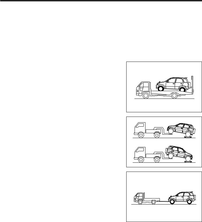
TOWING INFORMATION
When towing the model J100 follow the manner mentioned below.
CAUTION:
•Never perform towing, using sling type equipment.
Failure to observe this caution may lead to severe damage on the vehicle body.
JGI00020-00000
Flat bed type
We recommend this as the most desirable method.
CAUTION:
•Apply the parking brake securely.
•Be sure to tie-down the vehicle body to the carrier, using a tie-down wires. However, never apply excessive force to each hook on the vehicle body, for vehicle body may be severely damaged.
Wheel lift type
Use a towing dolly when towing the vehicle with the front wheels or rear wheels on ground.
WARNING:
•Never allow anyone to be in the vehicle being towed.
CAUTION:
•Be sure to secure the front or rear tires on the towing dolly.
•Never perform the towing, using sling type equipment. Failure to observe this caution may severely damage the vehicle body.
Emergency towing
This manner can be employed if the vehicle is equipped with a manual transmission and the road surface is hard and smooth. In this case, be certain to follow the WARNING and CAUTION mentioned below.
WARNING :
•The driver in the vehicle to be towed should always keep in mind that braking will require more force than usual when the engine is stopped, because the brake booster is not functioning when the engine is stopped.
JGI00021-00008 |
JGI00022-00009 |
JGI00023-00010 |
Downloaded from www.Manualslib.com manuals search engine
GI–11
•Never tow the vehicle at speed more than 30 km/h.
•Turn the ignition switch of the vehicle to be towed in the “ACC” position during the towing. Never pull out the key or turn the ignition switch to the “LOCK” position during the towing. Failure to observe this warning will loose controllability, causing an accident.
•Never tow the vehicle in this manner unless the wheels, axles, drive train, steering, and brakes are in a good condition.
CAUTION:
•Never tow an automatic transmission vehicle in this manner. Be sure to always use a towing dolly.
•Always pull the hook in a straight-ahead direction to prevent it from being damaged. Never pull it from side or in a vertical direction. Also, never pull it sharply.
•Never connect the towing rope, cable or such to the parts other than the hooks provided on the vehicle shell. Connection of the towing rope, cable or such to other pants than hooks may damage these components
•Ensure that the hooks are installed on the vehicle shell securely before towing.
1.Attach a sturdy rope, towing strap or cable to the towing hook.
2.A driver must ride in the vehicle being towed and control it.
3.Release the parking brake and shift the shift lever of manual transmission to the neutral position.
4.Select the center differential lock switch in the free position.
NOTE:
•If you cannot start the engine, ensure that the center differential lock mechanism is free by jacking up one of the wheels and making sure that the wheel turns freely.
Even if the indicator lamp in the combination meter shows that the differential lock is free, there is the possibility that it is not free actually.
5.Set the ignition switch to the “ACC” position.
6.Perform the towing.
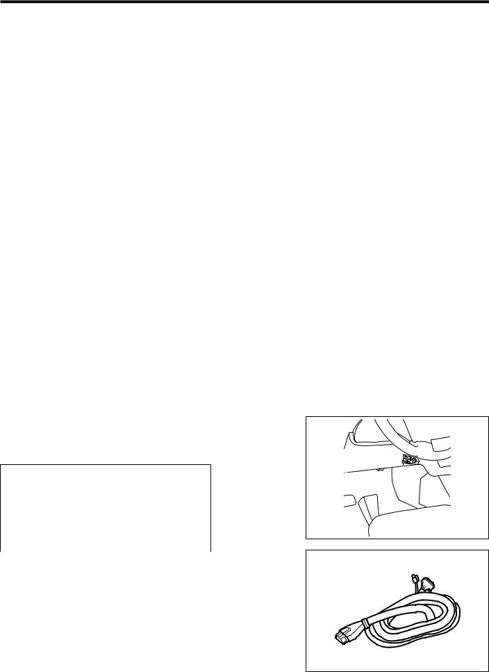
DIAGNOSIS CONNECTOR
The diagnosis connector is provided under the instrument panel at the driver’s seat side as shown.
Terminal table
Terminal number and name
q IG For DS-21 |
o T (ITC) |
|
|
e ABST |
!0SIO For DS-21 |
|
|
r ECUT |
!1EFIT |
|
|
i REV |
!3Body ground |
|
|
|
!6VF |
|
|
JGI00024-00000
JGI00025-00011
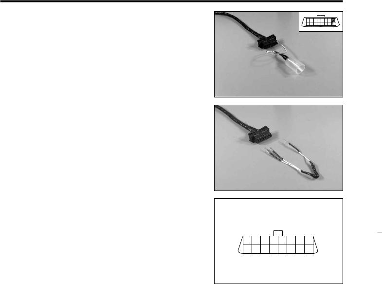
1.Be sure to connect the following SST when utilizing this connector, in order to prevent the terminals in the diagno-
sis connector from being damaged.
The shape of the SST end is the same as the diagnosis connector.
SST: 09991-87401-000
JGI00026-00012
Downloaded from www.Manualslib.com manuals search engine
GI–12
2.When measuring the engine tachometer, connect the following SST to the No.8 (REV) terminal of the above SST.
SST: 09991-87402-000
REV |
JGI00027-00013
3.Utilize the following SST when connecting the terminals in the SST for the diagnosis connector which is specified in the main text.
SST: 09991-87403-000 CAUTION:
∙Never connect the terminals other than that specified in the main text in each section. Failure to observe this caution may lead to serlus damage or malfunction.
JGI00028-00014
4.Reference
(1)Output of diagnosis code of EFI system. Connect the 11(EFIT) and 13 (Body ground)
(2)Output of diagnosis code of ABS system. Connect the 4(ECUT) and 13 (Body ground)
(3)Switching to the test of ABS system. Connect the 3(ABST) and 13 (Body ground)
(4)Vf output (oxygen sensor function) Connect the 16(VF) and 13(body ground)
(5)Output of diagnosis code of air bag system. Connect the 4(ECUT) and 13 (Body ground)
(6)To connect the tachometer
Connect a tachometer to 8(REV) terminal.
(7)Connection of the DS-21
Connect the DS-21 utilizing the following SST. The following SST is provided with the terminal for DS-21.
SST: 09991-87401-000
CAUTION:
∙Never connect the DS-21 in another way than that manner specified.
1 |
2 |
3 |
4 |
5 |
6 |
7 |
8 |
9 10 11 12 13 14 15 16
JGI00029-00015
Downloaded from www.Manualslib.com manuals search engine

GI–13
MODEL VARIATION
|
|
|
|
|
|
|
|
|
|
|
|
Specification |
|
|
|
|
|
|
|
|
General |
|
|
|
AUS |
|
|
|
|
EC |
|
|
||||||||||||||||||
|
|
|
|
|
|
|
|
|
|
|
|
|
|
|
|
|
|
|
|
|
|
|
|
|
|
|
|
|
|
|
|
|
|
|
|
|
|
|
|
|
|
|
|
|
|
|
|
|
|
|
Engine |
|
|
|
|
Handle position |
|
|
|
RHD |
|
|
|
LHD |
|
RHD |
|
RHD |
|
|
|
LHD |
|||||||||||||||||||||||||||||
|
|
|
|
|
|
|
|
|
|
|
|
|
|
|
|
|
|
|
|
|
|
|
|
|
|
|
|
|
|
|
|
|
|
|
|
|
|
|
|
|
|
|
|
|
|
|
|
|
|
|
|
|
|
|
|
|
|
|
|
|
|
|
|
|
|
Grade |
|
Lo |
|
|
Hi |
|
|
Lo |
Hi |
|
Lo |
Hi |
|
Lo |
|
Hi |
|
Lo |
|
Hi |
|||||||||||||||
|
|
|
|
|
|
|
|
|
|
|
|
|
|
|
|
|
|
|
|
|
|
|
|
|
|
|
|
|
|
|
|
|
|
|
|
|
|
|
|
|
|
|
|
|
|
|
|
|
||
|
|
|
|
|
|
|
|
|
|
|
|
|
Model code |
|
|
|
J100RG |
|
|
|
J100LG |
|
J100RG |
|
J100RG |
|
J100LG |
|||||||||||||||||||||||
HC-EJ |
|
|
|
|
|
|
|
|
|
|
|
|
|
|
|
|
|
|
|
|
|
|
|
|
|
|
|
|
|
|
|
|
|
|
|
|
|
|
|
|
||||||||||
|
|
|
|
|
|
|
|
|
5MT |
GMDE |
|
GMXE |
|
GMDE |
GMXE |
|
GMDEQ |
GMXEQ |
GMDEW |
GMXEW |
GMDEW |
GMXEW |
||||||||||||||||||||||||||||
|
|
|
|
|
|
|
|
|
|
|
|
|
|
|
|
4AT |
GPDE |
|
GPXE |
|
GPDE |
GPXE |
|
GPDEQ |
GPXEQ |
GPDEW |
GPXEW |
GPDEW |
GPXEW |
|||||||||||||||||||||
|
|
|
|
|
|
|
|
|
|
|
|
|
|
|
|
|
|
|
|
|
|
|
|
|
|
|
|
|
|
|
|
|
|
|
|
|
|
|
|
|
|
|
|
|
|
|
|
|
JGI00011-00000 |
|
Explanation of vehicle model code |
|
|
|
|
|
|
|
|
|
|
|
|
|
|
|
|
|
|
|
|
|
|
|
|||||||||||||||||||||||||||
|
|
|
|
|
|
|
|
|
|
|
|
|
|
|
|
|
|
|
|
|
|
|
|
|
|
|
|
|
|
|
|
|
|
|
|
|
|
|
|
|
|
|
|
|
|
|
||||
|
J1 |
|
0 |
|
0 |
|
L |
|
|
G |
- |
G |
|
M |
|
D |
|
E |
|
W |
|
|
|
|
|
|
|
|
|
|
|
|
|
|
||||||||||||||||
|
|
|
|
|
|
|
|
|
|
|
|
|
|
|
|
|
|
|
|
|
|
|
|
|
|
|
|
|
|
|
|
|
|
|
|
|
|
|
|
Model code |
|
|
|
|
|
|
|
|||
|
|
|
|
|
|
|
|
|
|
|
|
|
|
|
|
|
|
|
|
|
|
|
|
|
|
|
|
|
|
|
|
|
|
|
|
|
|
|
|
|
|
|
|
|
|
|
||||
|
|
|
|
|
|
|
|
|
|
|
|
|
|
|
|
|
|
|
|
|
|
|
|
|
|
|
|
|
|
|
|
|
|
|
|
|
|
|
|
|
|
|
|
|
|
|
||||
|
|
|
|
|
|
|
|
|
|
|
|
|
|
|
|
|
|
|
|
|
|
|
|
|
|
|
|
|
|
|
|
|
|
|
|
|
|
|
|
J1 : TERIOS |
|
|
|
|
|
|
|
|||
|
|
|
|
|
|
|
|
|
|
|
|
|
|
|
|
|
|
|
|
|
|
|
|
|
|
|
|
|
|
|
|
|
|
|
|
|
|
|
|
Drive system |
|
|
|
|
|
|
|
|||
|
|
|
|
|
|
|
|
|
|
|
|
|
|
|
|
|
|
|
|
|
|
|
|
|
|
|
|
|
|
|
|
|
|
|
|
|
|
|
|
|
|
|
|
|
|
|
||||
|
|
|
|
|
|
|
|
|
|
|
|
|
|
|
|
|
|
|
|
|
|
|
|
|
|
|
|
|
|
|
|
|
|
|
|
|
|
|
|
0 : Four-Wheel Drive Vehicle (Full-time 4WD) |
||||||||||
|
|
|
|
|
|
|
|
|
|
|
|
|
|
|
|
|
|
|
|
|
|
|
|
|
|
|
|
|
|
|
|
|
|
|
|
|
|
|
|
Engine type |
|
|
|
|
|
|
|
|||
|
Body type |
|
|
|
|
|
|
|
|
|
|
|
|
|
|
|
|
|
|
|
|
|
|
|
|
|
|
|
|
|
|
|
|
|
|
|
|
|
|
|||||||||||
|
|
|
|
|
|
|
|
|
|
|
|
|
|
|
|
|
|
|
|
|
|
|
|
|
|
|
|
|
|
|
0 : Type HC-EJ engine |
|
|
|
|
|
||||||||||||||
|
|
|
|
|
|
|
|
|
|
|
|
|
|
|
|
|
|
|
|
|
|
|
|
|
|
|
|
|
|
|
|
|
|
|
|
|||||||||||||||
|
G : Station |
|
|
|
|
|
|
|
|
|
|
|
|
|
|
|
|
|
|
|
|
|
|
|
|
|
|
|
|
|
|
|
|
|
|
|
|
|
|
|
|
|||||||||
|
|
|
wagon |
|
|
|
|
|
|
|
|
|
|
|
|
|
|
|
|
|
|
|
|
|
|
|
|
|
|
|
|
|
Steering position |
|
|
|
|
|
|
|
||||||||||
|
|
|
|
|
|
|
|
|
|
|
|
|
|
|
|
|
|
|
|
|
|
|
|
|
|
|
|
|
|
|
|
|
|
|
|
|
|
|
||||||||||||
|
Number of doors |
|
|
|
|
|
|
|
|
|
|
|
|
|
|
|
|
|
|
|
L : Left-Hand Drive Vehicle |
|
|
|
|
|
||||||||||||||||||||||||
|
|
|
|
|
|
|
|
|
|
|
|
|
|
|
|
|
|
|
|
|
|
|
|
|
||||||||||||||||||||||||||
|
G : Five Door |
|
|
|
|
|
|
|
|
|
|
|
|
|
|
|
|
|
|
|
|
|
|
|
|
|
|
|
|
|
R : Right-Hand Drive Vehicle |
|
|
|
|
|||||||||||||||
|
Transmission |
|
|
|
|
|
|
|
|
|
|
|
|
|
|
|
|
|
|
|
|
|
|
|
|
|
|
|
|
|
Fuel supply |
|
|
|
|
|
|
|
||||||||||||
|
|
|
|
|
|
|
|
|
|
|
|
|
|
|
|
|
|
|
|
|
|
|
|
|
|
|
|
|
|
|
|
|
|
|
|
|
||||||||||||||
|
|
|
|
|
|
|
|
|
|
|
|
|
|
|
|
|
|
|
|
|
|
|
|
|
|
|
|
|
|
|
|
|
|
|
|
|
||||||||||||||
|
M : Five-speed Manual Transmission |
|
|
|
|
|
|
|
|
|
|
|
|
E : EFI-equipped Engine |
|
|
|
|
|
|||||||||||||||||||||||||||||||
|
P : Four-speed Automatic Transmission |
|
|
|
|
|
|
|
|
|
|
|
|
|
|
|
|
|
|
|
|
|
|
|
||||||||||||||||||||||||||
|
Grade of model |
|
|
|
|
|
|
|
|
|
|
|
|
|
|
|
|
|
|
|
|
|
|
|
|
|
|
Destination |
|
|
|
|
|
|
|
|||||||||||||||
|
|
|
|
|
|
|
|
|
|
|
|
|
|
|
|
|
|
|
|
|
|
|
|
|
|
|
|
|
|
|
|
|
|
|||||||||||||||||
|
|
|
|
|
|
|
|
|
|
|
|
|
|
|
|
|
|
|
Non : General Specifications |
|
|
|
|
|||||||||||||||||||||||||||
|
|
|
|
|
|
|
|
|
|
|
|
|
|
|
|
|
|
|
|
|
|
|
||||||||||||||||||||||||||||
|
D : Low grade |
|
|
|
|
|
|
|
|
|
|
|
|
|
|
|
|
|
W : European Specifications |
|
|
|
|
|||||||||||||||||||||||||||
|
X : High grade |
|
|
|
|
|
|
|
|
|
|
|
|
|
|
|
|
|
Q : Australian Specifications |
|
|
|
|
|||||||||||||||||||||||||||
|
|
|
|
|
|
|
|
|
|
|
|
|
|
|
|
|
|
|
|
|
|
|
|
|
|
|
|
|
|
|
|
|
|
|
|
|
|
|
|
|
|
|
|
|
|
|
|
|
JGI00012-00000 |
|
Downloaded from www.Manualslib.com manuals search engine

GI–14
CHASSIS SERIAL NUMBER
STAMPED POSITION
The chassis number is stamped on the cowl panel at the right side in the engine compartment.
MANUFACTURER’S PLATE POSITION
The manufacturer’s plate is attached on the cowl panel.
Serial number
JGI00013-00004
Manufacturer’s plate
JGI00014-00005
CONTENTS OF MANUFACTURER’S PLATE
(1)General, Australian, Norwegian and Finnish specifications
q |
|
|
|
|
|
|
|
|
|
|
|
|
|
|
|
|
|
|
|
|
|
|
|
|
|
|
|
|
|
|
|
|
|
|
|
|
|
w |
|
|
|
|
|
|
|
|
|
|
|
|
|
|
|
|
|
|
|
|
|
|
|
|
|
|
|
|
|
|
|
|
|
|
|
||
e |
|
|
|
|
|
|
|
|
|
|
|
|
|
|
|
|
|
|
|
|
|
|
|
|
|
|
|
|
|
|
|
||||||
r |
|
|
|
|
|
|
|
|
|
|
|
|
|
t |
|
|||
|
|
|
|
|
|
|
|
|
|
|
|
|
|
|
|
|||
y |
|
|
|
|
|
|
|
u |
|
|||||||||
|
|
|
|
|
|
!4 |
q Manufacturer’s name, Country |
|||||||||||
|
|
|
|
|||||||||||||||
|
|
|
|
|
|
|
|
|
|
|
|
|
|
|
|
|
|
w Vehicle model |
|
|
|
|
|
|
|
|
|
|
|
|
|
|
|
|
i |
e Chassis No. |
|
|
|
|
|
|
|
|
|
|
|
|
|
|
|
|
|
|||
|
|
|
|
|
|
|
|
|
|
|
|
|
|
|
|
|
|
r Engine type |
|
|
|
|
|
|
|
|
|
|
|
|
|
|
|
|
o |
t Engine displacement |
|
|
|
|
|
|
|
|
|
|
|
|
|
|
|
|
|
|||
|
|
|
|
|
|
|
|
|
|
|
|
|
|
|
|
|
|
y Body colors |
|
|
|
|
|
|
|
|
|
|
|
|
|
|
|
|
|
|
u Trim code |
|
|
|
|
|
|
|
|
|
|
|
|
|
|
|
|
|
|
i Engine number |
|
|
|
|
|
|
|
|
|
|
|
|
|
|
|
|
|
|
o Manufacturer’s name in Japanese |
q |
|
|
|
|
|
|
|
|
|
|
|
|
!0Gross vehicle weight |
|||||
|
|
|
|
|
|
|
|
|
|
|
|
|||||||
|
|
|
|
|
|
|
|
|
|
|
|
|
|
|
|
|
!5 |
!1Gross combination weight |
|
|
|
|
|
|
|
|
|
|
|
!2Maximum permissible front axle weight |
|||||||
|
|
|
|
|
|
|
|
|
|
|||||||||
|
|
|
|
|
|
|
|
|
|
|
|
|
|
|
|
|
e |
!3Maximum permissible rear axle weight |
|
|
|
|
|
|
|
|
|
|
|
|
|
|
|
|
|
||
|
|
|
|
|
|
|
|
|
|
|
|
|
|
|
|
|
!0 |
!4Production month-year (Only for AUS spec.) |
|
|
|
|
|
|
|
|
|
|
|
!5Authorized number of W.V.T.A. |
|||||||
|
|
|
|
|
|
|
|
|
|
|
|
|
|
|
|
|
!1 (Only for European specification.) |
|
|
|
|
|
|
|
|
|
|
|
|
|
|
|
|
|
|
||
|
|
|
|
|
|
|
|
|
|
|
!2 |
|
||||||
|
|
|
|
|
|
|
|
|
|
|
||||||||
w |
|
|
|
|
|
|
|
|
|
!3 |
|
|||||||
|
|
|
|
|
|
|
|
|||||||||||
|
|
|
|
|
|
|
|
|
|
|
y |
|
||||||
|
|
|
|
|
|
|
|
|
|
|
||||||||
r |
|
|
|
|
|
|
|
|
|
|
|
|||||||
|
|
|
|
|
|
|
|
|
|
|
||||||||
JGI00015-00006
Downloaded from www.Manualslib.com manuals search engine
ENGINE NUMBER AND ENGINE TYPE STAMPED POSITIONS
•The engine number is stamped on the cylinder block.
•The engine type is indicated by embossed letters on the cylinder block.
BODY COLOR INFORMATION
Body color name |
Code |
|
|
|
|
Silver metallic |
S07 |
|
|
|
|
Black metallic |
6A5 |
|
|
|
|
Red mica metallic |
R24 |
|
|
|
|
Turquoise mica metallic |
B36 |
|
|
|
|
Purplish blue mica |
B38 |
|
|
|
|
Violet metallic |
P05 |
|
|
|
|
Two-tone color |
NF7 |
|
Silver metallic / Silver metallic |
||
|
||
|
|
|
Two-tone color |
NF2 |
|
Black metallic / Silver metallic |
||
|
||
|
|
|
Two-tone color |
NF0 |
|
Red mica metallic / Silver metallic |
||
|
||
|
|
|
Two-tone color |
ND9 |
|
Turquoise mica metallic / Silver metallic |
||
|
||
|
|
|
Two-tone color |
NG1 |
|
Purplish blue mica / Silver metallic |
||
|
||
Two-tone color |
NG2 |
|
Violet metallic / Silver metallic |
||
|
||
|
|
GI–15
Serial number stamped position
JGI00016-00007
JGI00017-00000
Downloaded from www.Manualslib.com manuals search engine
GI–16
COLOR CODE IN THE WORLD
|
|
|
|
|
|
|
|
|
|
Color code |
|
|
||
|
|
|
|
Color name |
|
|
|
|
|
|
|
|||
DAIHATSU |
AKZO |
DUPONT |
ICI |
SPIES |
STANDOX |
|||||||||
|
|
|
|
|
|
|
||||||||
|
|
|
|
|
|
|
HECKER |
|||||||
|
|
|
|
|
|
|
|
|
|
|
|
|
||
Silver metallic |
|
|
S07 |
DAHS07 |
L8842 |
B127B |
97076 |
S07 |
||||||
|
|
|
|
|
|
|
|
|
|
|
|
|
|
|
Black metallic |
|
|
6A5 |
DAH6A5 |
G8742 |
A403B |
96326 |
6A5 |
||||||
|
|
|
|
|
|
|
|
|
|
|
|
|
|
|
Red mica metallic |
|
|
R24 |
DAHR24 |
F2213 |
FCN6B |
33273 |
R24 |
||||||
|
|
|
|
|
|
|
|
|
|
|
|
|
|
|
Turquoise mica metallic |
|
|
B36 |
DAHB36 |
F2855 |
HMG7B |
55174 |
B36 |
||||||
|
|
|
|
|
|
|
|
|
|
|
|
|
|
|
Purplish blue mica |
|
|
B38 |
DAHB38 |
F3425 |
JNE4B |
55603 |
B38 |
||||||
|
|
|
|
|
|
|
|
|
|
|
|
|
|
|
Violet metallic |
|
|
P05 |
DAHP05 |
F3426 |
JNE5B |
40868 |
P05 |
||||||
|
|
|
|
|
|
|
|
|
|
|
|
|
|
|
White |
|
|
W09 |
DAHW09 |
K9344 |
XM48 |
16461 |
W09 |
||||||
|
|
|
|
|
|
|
|
|
|
|
|
|
|
|
Two-tone color |
|
NF7 |
S07 |
DAHS07 |
L8824 |
B127B |
97076 |
S07 |
||||||
|
|
|
|
|
|
|||||||||
Silver metallic / Silver metallic |
|
S07 |
DAHS07 |
L8842 |
B127B |
97076 |
S07 |
|||||||
|
|
|
|
|
|
|
|
|
|
|
|
|
|
|
Two-tone color |
|
NF2 |
6A5 |
DAH6A5 |
G8742 |
A403B |
96326 |
6A5 |
||||||
|
|
|
|
|
|
|||||||||
Black metallic / Silver metallic |
|
S07 |
DAHS07 |
L8842 |
B127B |
97076 |
S07 |
|||||||
|
|
|
|
|
|
|
|
|
|
|
|
|
|
|
Two-tone color |
|
NF0 |
R24 |
DAHR24 |
F2213 |
FCN6B |
33273 |
R24 |
||||||
|
|
|
|
|
|
|||||||||
Red mica metallic / Silver metallic |
|
S07 |
DAHS07 |
L8842 |
B127B |
97076 |
S07 |
|||||||
|
|
|
|
|
|
|
|
|
|
|
|
|
|
|
Two-tone color |
|
ND9 B36 |
DAHB36 |
F2855 |
HMG7B |
55174 |
B36 |
|||||||
Turquoise mica metallic / Silver metallic |
DAHS07 |
L8842 |
B127B |
97076 |
S07 |
|||||||||
|
S07 |
|||||||||||||
Two-tone color |
|
NG1 B38 |
DAHB38 |
F3425 |
JNE4B |
55603 |
B38 |
|||||||
Purplish blue mica / Silver metallic |
DAHS07 |
L8842 |
B127B |
97076 |
S07 |
|||||||||
|
S07 |
|||||||||||||
Two-tone color |
|
NG2 P05 |
DAHP05 |
F3426 |
JNE5B |
40868 |
P05 |
|||||||
Violet metallic / Silver metallic |
DAHS07 |
L8842 |
B127B |
97076 |
S07 |
|||||||||
|
S07 |
|||||||||||||
Two-tone color |
|
NC1 W09 |
DAHW09 |
K9344 |
XM48 |
16461 |
W09 |
|||||||
White / Silver metallic |
|
DAHS07 |
L8842 |
B127B |
97076 |
S07 |
||||||||
|
|
S07 |
||||||||||||
|
|
|
|
|
|
|
|
|
|
|
|
|
JGI00018-00000 |
|
TRIM CODE |
|
|
|
|
|
|
|
|
||||||
|
|
|
|
|
|
|
|
|
|
|
|
|||
F |
|
C |
|
S5 |
|
Trim color code (Serial c |
|
|
|
|
|
|||
Serial code
Seat main material
F: Fabric
S: Gray
JGI00019-00000
Downloaded from www.Manualslib.com manuals search engine

DAIHATSU
MA
J100
MAINTENANCE
MAINTENANCE REQUIREMENTS ... |
MA– 2 |
MAINTENANCE SCHEDULE ............ |
MA– 3 |
SCHEDULE FOR SEVERE |
|
DRIVING ..................................... |
MA– 5 |
MAINTENANCE OPERATION ........... |
MA– 6 |
ENGINE ............................................. |
MA– 6 |
COLD ENGINE OPERATION ........ |
MA– 6 |
HOT ENGINE OPERATION .......... |
MA–13 |
CHASSIS ........................................... |
MA–26 |
BRAKE FLUID .............................. |
MA–26 |
BRAKE PEDAL ............................. |
MA–27 |
PARKING BRAKE HANDLE .......... |
MA–27 |
BRAKE HOSE & TUBE ................. |
MA–28 |
FRONT BRAKE ............................. |
MA–29 |
REAR BRAKE ............................... |
MA–32 |
BRAKE BOOSTER HOSE ............. |
MA–34 |
BRAKE MASTER CYLINDER ........ |
MA–35 |
MUFFLER AND EXHAUST PIPE ... |
MA–37 |
AUTOMATIC TRANSMISSION ..... MA–37 |
|
CLUTCH ....................................... |
MA–38 |
MANUAL TRANSMISSION, |
|
TRANSFER, FRONT AND REAR |
|
DIFFERENTIAL ........................... |
MA–39 |
PROPELLER SHAFT ..................... |
MA–40 |
DRIVE SHAFT ............................... |
MA–40 |
WHEEL HUB NUT ........................ |
MA–40 |
WHEEL BEARING ........................ |
MA–40 |
STEERING SYSTEM ..................... |
MA–41 |
WHEEL ALIGNMENT .................... |
MA–42 |
SHOCK ABSORBER ..................... |
MA–43 |
SUSPENSION ARM, CONTROL |
|
ARM & DUST COVER ................. |
MA–43 |
|
JMA00001-00000 |
NO. 9710-JE
Downloaded from www.Manualslib.com manuals search engine

MA–2
MAINTENANCE REQUIREMENTS
The scheduled maintenance service is important to ensure trouble-free, safe and economical driving. Failure to perform the scheduled maintenance may cause an accident or serious damage.
If you conduct the periodical maintenance, Daihatsu car owners may reduce the chance of accidents or car problems. Furthermore, it becomes possible for you to find at an earlier stage malfunctions which may lead to serious damages. Consequently, potential vehicle damage can be prevented or the degree of the damage can be minimized.
Therefore, all of the persons who are concerned with servicing the Daihatsu vehicles should offer the periodical maintenance service to Daihatsu car owners in order that they may be protected from accidents or unexpected problems.
To prevent malfunctions in advance, however, conducting the periodical maintenance service only is insufficient. It is essential that owners themselves perform maintenance, such as the pre-starting check described in the owner’s manual, so that the vehicle exhibits no abnormal change or phenomenon. Hence, please explain to owners about the necessity of maintenance performed by them. However, malfunction may occur on those vehicles which are always checked by their owners. For instance, if a part instructed to be replaced periodically should be used beyond the replacement intervals and the life of the part has expired, there are cases where malfunction occurs suddenly despite the fact that no malfunction has taken place until yesterday. To prevent such malfunction in advance, be sure to replace parts recommended to be replaced periodically at the specified replacement intervals.
This section describes those items of the scheduled maintenance service recommended by the Daihatsu and their intervals. Be sure to observe the maintenance schedule.
JMA00002-00000
Downloaded from www.Manualslib.com manuals search engine
MA–3
MAINTENANCE SCHEDULE
NOTE:
∙Perform the periodical maintenance at the specified mileage or the time whichever comes first, unless otherwise specified.
∙Continue to perform the periodical maintenance after 100,000 km (60,000 miles) at the same intervals as before 100,000 km.
∙If the vehicle should be operated under severe driving conditions, operated occasionally, operated in dusty areas, repeating short trip, operated under extremely cold climate and/or on salted roads, it is necessary to perform some maintenance items more frequently than the regular maintenance schedule.
∙This maintenance schedule prepared based on requirements mentioned in the owner’s manual which are to be performed by the Daihatsu owner thoroughly.
ª···Check or inspect. Á···Change or replace.
|
|
|
|
×1000 km |
1 |
10 |
20 |
30 |
40 |
50 |
60 |
|
70 |
80 |
90 |
100 |
See |
|
|
|
|
|
|
|
|
|
|
|
|
|
|
|
|
|
|
Section |
Item |
What to do |
Inspection interval ×1000 miles |
0.6 |
6 |
12 |
18 |
24 |
30 |
36 |
|
42 |
48 |
54 |
60 |
||
|
page |
||||||||||||||||
|
|
|
|
|
|
|
|
|
|
|
|
|
|
|
|
|
|
|
|
|
|
Years |
— |
0.5 |
1 |
1.5 |
2 |
2.5 |
3 |
|
3.5 |
4 |
4.5 |
5 |
|
|
|
|
|
|
|
|
|
|
|
|
|
|
|
|
|
|
|
|
Air cleaner element |
Cleaning |
|
|
|
|
ª |
|
|
Á |
|
|
|
ªÁ |
|
|
MA–6 |
|
Check |
|
|
|
|
|
|
|
|
||||||||
|
|
∙ Damage |
|
|
|
|
|
|
|
|
|
|
|
|
|
|
|
|
|
|
|
|
|
|
|
|
|
|
|
|
|
|
|
|
|
|
Valve clearance |
Check & adjustment |
|
|
|
|
|
|
ª |
|
|
|
|
|
ª |
|
MA–18 |
|
Engine oil & oil filter |
Change (Use API: SG or higher grade) |
|
|
|
Every 12,000 km |
|
|
|
MA–13 |
|||||||
|
|
|
|
|
|
|
|
|
|
|
|
|
|
|
|
|
|
|
Fuel filter |
Change |
|
|
|
|
|
Every 100,000 km |
|
|
|
MA–9 |
|||||
|
|
|
|
|
|
|
|
|
|
|
|
|
|
|
|
|
|
|
|
Check |
|
|
|
|
|
|
|
|
|
|
|
|
|
|
|
|
Fuel line & connections |
∙ Crack |
|
|
|
|
|
Every 40,000 km |
|
|
|
|
|||||
|
∙ Tightness |
|
|
|
|
|
|
|
|
MA–8 |
|||||||
|
(Including fuel hoses) |
|
|
|
|
|
|
|
|
||||||||
|
∙ Leakage |
|
|
|
|
|
|
|
|
|
|
|
|
|
|
|
|
|
|
|
|
|
|
|
|
|
|
|
|
|
|
|
|
|
|
|
|
∙ Damage |
|
|
|
|
|
|
|
|
|
|
|
|
|
|
|
|
|
|
|
|
|
|
|
|
|
|
|
|
|
|
|
|
|
Engine |
Coolant (Long-life coolant) |
Change |
|
|
|
|
|
Every two years |
|
|
|
|
MA–23 |
||||
|
Drive belt |
Check |
|
|
|
|
|
|
|
|
|
|
|
|
|
|
|
|
∙ Tension |
|
|
|
|
ª |
|
|
ª |
|
|
|
ª |
|
|
||
|
(Alternator, water pump, |
|
|
|
|
|
|
|
|
MA–6 |
|||||||
|
∙ Crack |
|
|
|
|
|
|
|
|
||||||||
|
power steering) |
|
|
|
|
|
|
|
|
|
|
|
|
|
|
|
|
|
∙ Damage |
|
|
|
|
|
|
|
|
|
|
|
|
|
|
|
|
|
|
|
|
|
|
|
|
|
|
|
|
|
|
|
|
|
|
|
|
|
|
|
|
|
|
|
|
|
|
|
|
|
|
|
|
|
|
|
|
|
|
|
|
Every 100,000 km |
|
|
|
Refer |
|||||
|
Timing belt |
Change |
|
|
|
|
|
|
|
|
to EM |
||||||
|
|
|
|
|
|
|
|
|
|
|
|
|
|
|
|
|
section. |
|
|
|
|
|
|
|
|
|
|
|
|
|
|
|
|
|
|
|
|
Cleaning & check |
|
|
|
|
|
|
|
|
|
|
|
|
|
|
|
|
Spark plug |
∙ Condition |
|
|
|
|
ª |
|
|
ª |
|
|
|
ª |
|
MA–14 |
|
|
∙ Gap |
|
|
|
|
|
|
|
|
||||||||
|
|
∙ Damage |
|
|
|
|
|
|
|
|
|
|
|
|
|
|
|
|
Ignition timing |
Check & adjustment |
|
|
|
|
ª |
|
|
ª |
|
|
|
ª |
|
MA–21 |
|
|
Blow-by gas recirculation |
Check |
|
|
|
|
|
|
ª |
|
|
|
|
|
ª |
|
|
|
hose (Positive crankcase |
∙ Connection |
|
|
|
|
|
|
|
|
|
|
MA–7 |
||||
|
ventilation hose) |
∙ Damage |
|
|
|
|
|
|
|
|
|
|
|
|
|
|
|
Exhaust |
|
Check |
|
|
|
|
|
|
ª |
|
|
|
|
|
ª |
|
|
emission |
Charcoal canister |
∙ Function |
|
|
|
|
|
|
|
|
|
|
MA–11 |
||||
control |
|
∙ Damage |
|
|
|
|
|
|
|
|
|
|
|
|
|
|
|
system |
Evaporative emission hoses |
Change |
|
|
|
|
|
Every eight years |
|
|
|
MA–12 |
|||||
|
|
|
|
|
|
|
|
|
|||||||||
|
|
|
|
|
|
|
|
|
|
|
|
|
|
|
|
|
|
|
Exhaust pipe & muffler |
Check |
|
|
|
|
ª |
|
|
ª |
|
|
|
ª |
|
|
|
|
∙ Tightness |
|
|
|
|
|
|
|
|
MA–37 |
|||||||
|
mounting |
|
|
|
|
|
|
|
|
||||||||
|
|
∙ Damage |
|
|
|
|
|
|
|
|
|
|
|
|
|
|
|
* Replace every 10,000 km when API SF grade oil is used.
Downloaded from www.Manualslib.com manuals search engine

MA–4
ª···Check or inspect. Á···Change or replace.
|
|
|
|
×1000 km |
1 |
10 |
20 |
30 |
40 |
50 |
60 |
70 |
80 |
90 |
100 |
See |
|
|
|
|
|
|
|
|
|
|
|
|
|
|
|
|
|
||
Section |
Item |
What to do |
Inspection interval ×1000 miles |
0.6 |
6 |
12 |
18 |
24 |
30 |
36 |
42 |
48 |
54 |
60 |
|||
page |
|||||||||||||||||
|
|
|
|
|
|
|
|
|
|
|
|
|
|
|
|
||
|
|
|
|
Years |
— |
0.5 |
1 |
1.5 |
2 |
2.5 |
3 |
3.5 |
4 |
4.5 |
5 |
|
|
|
|
|
|
|
|
|
|
|
|
|
|
|
|
|
|
|
|
|
|
Check |
|
|
|
|
|
|
|
|
|
|
|
|
|
|
|
|
Clutch |
∙ Free travel |
|
|
|
|
ª |
|
ª |
|
ª |
|
ª |
|
ª |
MA–38 |
|
|
|
∙ Reserve travel |
|
|
|
|
|
||||||||||
|
|
∙ Damage |
|
|
|
|
|
|
|
|
|
|
|
|
|
|
|
|
|
|
|
|
|
|
|
|
|
|
|
|
|
|
|
|
|
|
Manual transmission |
Change |
|
|
|
|
|
|
Á |
|
|
|
Á |
|
|
MA–39 |
|
|
∙ Oil |
|
|
|
|
|
|
|
|
|
|||||||
|
|
|
|
|
|
|
|
|
|
|
|
|
|
|
|
|
|
|
Automatic transmission |
Change |
|
|
|
|
|
Every 80,000 km |
|
|
|
MA–37 |
|||||
|
∙ Fluid |
|
|
|
|
|
|
|
|
||||||||
|
|
|
|
|
|
|
|
|
|
|
|
|
|
|
|
||
|
|
|
|
|
|
|
|
|
|
|
|
|
|
|
|
|
|
Power |
Automatic transmission |
Check |
|
|
|
|
|
Every 40,000 km |
|
|
|
MA–38 |
|||||
Oil cooler hose |
∙ Crack, scratch, cut, twist and swelling |
|
|
|
|
|
|
||||||||||
train |
|
|
|
|
|
|
|
|
|
|
|
|
|
|
|
|
|
|
Change |
|
|
|
|
|
|
|
|
|
|
|
|
|
|
||
system |
Transfer |
|
|
|
|
|
|
Á |
|
|
|
Á |
|
|
MA–39 |
||
|
∙ Oil |
|
|
|
|
|
|
|
|
|
|||||||
|
Differential (Front & Rear) |
Change |
|
|
|
|
|
|
Á |
|
|
|
Á |
|
|
MA–39 |
|
|
∙ Oil |
|
|
|
|
|
|
|
|
|
|||||||
|
|
|
|
|
|
|
|
|
|
|
|
|
|
|
|
|
|
|
|
Check |
|
|
|
|
|
|
|
|
|
|
|
|
|
|
|
|
Propeller shaft |
∙ Tightness |
|
|
|
|
ª |
|
ª |
|
ª |
|
ª |
|
ª |
MA–40 |
|
|
|
∙ Rattle |
|
|
|
|
|
||||||||||
|
|
∙ Damage |
|
|
|
|
|
|
|
|
|
|
|
|
|
|
|
|
|
|
|
|
|
|
|
|
|
|
|
|
|
|
|
|
|
|
Drive shaft boot |
Check |
|
|
|
|
ª |
|
ª |
|
ª |
|
ª |
|
ª |
MA–40 |
|
|
|
∙ Damage |
|
|
|
|
|
||||||||||
|
|
|
|
|
|
|
|
|
|
|
|
|
|
|
|
||
|
|
|
|
|
|
|
|
|
|
|
|
|
|
|
|
|
|
|
|
Check |
|
|
|
|
|
|
|
|
|
|
|
|
|
|
|
Suspen- |
Shock absorber |
∙ Function |
|
|
|
|
ª |
|
ª |
|
ª |
|
ª |
|
ª |
MA–43 |
|
|
∙ Oil leakage (Shock absorber) |
|
|
|
|||||||||||||
sion |
|
∙ Damage |
|
|
|
|
|
|
|
|
|
|
|
|
|
|
|
system |
|
|
|
|
|
|
|
|
|
|
|
|
|
|
|
|
|
Suspension arm (Front) |
Check |
|
|
|
|
|
|
ª |
|
|
|
ª |
|
|
|
||
|
|
|
|
|
|
|
|
|
|
|
|||||||
|
Control arm (Rear) |
∙ Tightness |
|
|
|
|
|
|
|
|
|
MA–43 |
|||||
|
Dust boots |
∙ Damage |
|
|
|
|
|
|
|
|
|
|
|
|
|
|
|
Running |
|
Check |
|
|
|
|
|
|
|
|
|
|
|
|
|
|
|
Wheel bearing |
∙ Tightness |
|
|
|
|
|
|
ª |
|
|
|
ª |
|
|
MA–40 |
||
system |
|
|
|
|
|
|
|
|
|
||||||||
|
|
∙ Damage |
|
|
|
|
|
|
|
|
|
|
|
|
|
|
|
|
|
Check |
|
|
|
|
|
|
|
|
|
|
|
|
|
|
|
|
|
∙ Free play (Steering wheel) |
|
|
ª |
|
ª |
|
ª |
|
ª |
|
ª |
|
|||
|
Steering linkage, gear box |
∙ Tightness |
|
|
|
|
|||||||||||
|
|
|
|
|
|
|
|
|
|
|
|
|
|
MA–41 |
|||
Steering |
|
∙ Rattle |
|
|
|
|
|
|
|
|
|
|
|
|
|
|
|
|
∙ Damage |
|
|
|
|
|
|
|
|
|
|
|
|
|
|
||
system |
|
|
|
|
|
|
|
|
|
|
|
|
|
|
|
|
|
Wheel alignment |
Check |
|
|
|
|
|
|
ª |
|
|
|
ª |
|
|
MA–42 |
||
|
|
|
|
|
|
|
|
|
|
||||||||
|
∙ Toe-in |
|
|
|
|
|
|
|
|
|
|||||||
|
|
|
|
|
|
|
|
|
|
|
|
|
|
|
|
|
|
|
Fluid hose |
Check |
|
|
|
|
|
|
Every 4 years |
|
|
|
|
MA–42 |
|||
|
∙ Crack, scratch, cut, twist and swelling |
|
|
|
|
|
|
|
|
||||||||
|
|
|
|
|
|
|
|
|
|
|
|
|
|
||||
|
|
|
|
|
|
|
|
|
|
|
|
|
|
|
|
|
|
Downloaded from www.Manualslib.com manuals search engine

MA–5
ª···Check or inspect. Á···Change or replace.
|
|
|
|
×1000 km |
1 |
10 |
20 |
30 |
|
40 |
50 |
60 |
70 |
80 |
90 |
100 |
See |
Section |
Item |
What to do |
Inspection interval |
|
|
|
|
|
|
|
|
|
|
|
|
|
|
×1000 miles |
0.6 |
6 |
12 |
18 |
|
24 |
30 |
36 |
42 |
48 |
54 |
60 |
|||||
|
page |
||||||||||||||||
|
|
|
|
|
|
|
|
|
|
|
|
|
|
|
|
|
|
|
|
|
|
Years |
— |
0.5 |
1 |
1.5 |
|
2 |
2.5 |
3 |
3.5 |
4 |
4.5 |
5 |
|
|
|
|
|
|
|
|
|
|
|
|
|
|
|
|
|
|
|
|
|
Check |
|
|
|
|
|
|
|
|
|
|
|
|
|
|
|
|
Brake pedal & Parking brake |
∙ Free play (Brake pedal) |
|
|
|
|
ª |
|
ª |
|
ª |
|
ª |
|
ª |
MA–27 |
|
|
|
∙ Reserve travel (Brake pedal) |
|
|
|
|
|||||||||||
|
|
∙ Working travel (Parking brake) |
|
|
|
|
|
|
|
|
|
|
|
|
|
|
|
|
|
|
|
|
|
|
|
|
|
|
|
|
|
|
|
|
|
|
|
Check |
|
|
|
|
ª |
|
ª |
|
ª |
|
ª |
|
ª |
|
|
|
Disc pad |
∙ Wear |
|
|
|
|
|||||||||||
|
|
|
|
|
|
|
|
|
|
|
|
|
|
|
MA–29 |
||
|
|
∙ Damage |
|
|
|
|
|
|
|
|
|
|
|
|
|
|
|
|
|
|
|
|
|
|
|
|
|
|
|
|
|
|
|
|
|
|
|
Check |
|
|
|
|
|
|
|
|
|
|
|
|
|
|
|
Brake |
Brake hose, tube and P & B |
∙ Leakage (Fluid level, connection) |
|
|
|
ª |
|
ª |
|
ª |
|
ª |
|
ª |
MA–28 |
||
system |
valve |
∙ Loose clamp |
|
|
|
|
|
||||||||||
|
∙ Damage |
|
|
|
|
|
|
|
|
|
|
|
|
|
|
|
|
|
|
|
|
|
|
|
|
|
|
|
|
|
|
|
|
|
|
|
Brake fluid |
Change |
|
|
|
|
|
|
|
Every 2 years |
|
|
|
|
MA–26 |
||
|
|
|
|
|
|
|
|
|
|
|
|
|
|
|
|
|
|
|
|
Check |
|
|
|
|
ª |
|
ª |
|
ª |
|
ª |
|
ª |
|
|
|
Brake lining |
∙ Wear |
|
|
|
|
|||||||||||
|
|
|
|
|
|
|
|
|
|
|
|
|
|
|
MA–32 |
||
|
|
∙ Damage |
|
|
|
|
|
|
|
|
|
|
|
|
|
|
|
|
Brake booster vacuum hose |
Check |
|
|
|
|
|
|
|
Every 4 years |
|
|
|
|
MA–34 |
||
|
|
|
|
|
|
|
|
|
|
|
|
|
|
|
|
|
|
|
Master & wheel cylinder |
Check |
|
|
|
|
|
|
|
Every 2 years |
|
|
|
|
MA–35 |
||
|
∙ Leakage |
|
|
|
|
|
|
|
|
|
|
|
|||||
|
|
|
|
|
|
|
|
|
|
|
|
|
|
|
|
|
|
|
|
|
|
|
|
|
|
|
|
|
|
|
|
|
|
|
|
Chassis & |
Wheel hub nut, other bolts & |
Check |
|
|
|
|
ª |
|
ª |
|
ª |
|
ª |
|
ª |
MA–40 |
|
body |
nuts |
∙ Tightness |
|
|
|
|
|
||||||||||
|
|
|
|
|
|
|
|
|
|
|
|
|
|
|
JMA00003-00000 |
||
SCHEDULE FOR SEVERE DRIVING |
|
|
|
|
|
|
|
|
|
|
|
|
|
|
|
||
|
|
|
|
|
|
|
ª···Check or inspect. Á···Change or replace. |
||||||||||
|
|
|
|
×1000 km |
1 |
10 |
20 |
30 |
|
40 |
50 |
60 |
70 |
80 |
90 |
100 |
See |
Section |
Item |
What to do |
Inspection interval |
|
|
|
|
|
|
|
|
|
|
|
|
|
|
×1000 miles |
0.6 |
6 |
12 |
18 |
|
24 |
30 |
36 |
42 |
48 |
54 |
60 |
|||||
|
page |
||||||||||||||||
|
|
|
|
|
|
|
|
|
|
|
|
|
|
|
|
|
|
|
|
|
|
Years |
— |
0.5 |
1 |
1.5 |
2 |
2.5 |
3 |
3.5 |
4 |
4.5 |
5 |
|
|
|
|
|
|
|
|
|
|
|
|
|
|
|
|
|
|
|
|
|
Engine oil & oil filter |
Change |
|
|
|
|
|
|
Every 5,000 km |
|
|
|
MA–13 |
||||
|
|
|
|
|
|
|
|
|
|||||||||
Engine |
Air cleaner element |
Check & cleaning |
|
|
|
Check and cleaning: Every 5,000 km |
|
MA–6 |
|||||||||
|
∙ Damage |
|
|
|
Replacement: Every 20,000 km |
|
|
||||||||||
|
|
Change |
|
|
|
|
|
|
|||||||||
|
|
|
|
|
|
|
|
|
|
|
|
|
|
|
|
|
|
|
|
|
|
|
|
|
|
|
|
|
|
|
|
|
|
|
|
Exhaust |
|
Check |
|
|
|
|
|
|
|
|
|
|
|
|
|
|
|
emission |
Exhaust pipe and mounting |
∙ Tightness |
|
|
|
ª |
ª |
ª |
ª |
ª |
ª |
ª |
ª |
ª |
ª |
MA–37 |
|
control |
|
∙ Damage |
|
|
|
|
|||||||||||
system |
|
|
|
|
|
|
|
|
|
|
|
|
|
|
|
|
|
|
Manual transmission |
Change |
|
|
|
|
|
Every 25,000 km |
|
|
|
MA–39 |
|||||
|
∙ Fluid |
|
|
|
|
|
|
|
|
||||||||
|
|
|
|
|
|
|
|
|
|
|
|
|
|
|
|
|
|
|
|
|
|
|
|
|
|
|
|
|
|
|
|
|
|
|
|
Power |
Automatic transmission |
Change |
|
|
|
|
|
Every 50,000 km |
|
|
|
MA–37 |
|||||
∙ Fluid |
|
|
|
|
|
|
|
|
|||||||||
train |
|
|
|
|
|
|
|
|
|
|
|
|
|
|
|
|
|
|
|
|
|
|
|
|
|
|
|
|
|
|
|
|
|
|
|
|
Change |
|
|
|
|
|
|
|
|
|
|
|
|
|
|
|
|
system |
Transfer |
|
|
|
|
|
Every 25,000 km |
|
|
|
MA–39 |
||||||
|
∙ Fluid |
|
|
|
|
|
|
|
|
||||||||
|
|
|
|
|
|
|
|
|
|
|
|
|
|
|
|
|
|
|
|
|
|
|
|
|
|
|
|
|
|
|
|
|
|
|
|
|
Differential (Front & Rear) |
Change |
|
|
|
|
|
Every 25,000 km |
|
|
|
MA–39 |
|||||
|
∙ Fluid |
|
|
|
|
|
|
|
|
||||||||
|
|
|
|
|
|
|
|
|
|
|
|
|
|
|
|
|
|
|
|
|
|
|
|
|
|
|
|
|
|
|
|
|
|
|
|
Steering |
|
Check |
|
|
|
ª |
ª |
ª |
ª |
ª |
ª |
ª |
ª |
ª |
ª |
|
|
Steering linkage |
∙ Tightness |
|
|
|
MA–41 |
||||||||||||
system |
|
∙ Damage |
|
|
|
|
|||||||||||
|
|
|
|
|
|
|
|
|
|
|
|
|
|
|
|
|
|
|
|
|
|
|
|
|
|
|
|
|
|
|
|
|
|
|
|
|
|
Check |
|
|
|
ª |
ª |
ª |
ª |
ª |
ª |
ª |
ª |
ª |
ª |
|
|
|
Disc & disc pad |
∙ Wear |
|
|
|
||||||||||||
|
|
|
|
|
|
|
|
|
|
|
|
|
|
|
MA–29 |
||
Brake |
|
∙ Damage |
|
|
|
|
|
|
|
|
|
|
|
|
|
|
|
system |
|
|
|
|
|
|
|
|
|
|
|
|
|
|
|
|
|
|
Check |
|
|
|
ª |
ª |
ª |
ª |
ª |
ª |
ª |
ª |
ª |
ª |
|
||
|
|
|
|
|
|||||||||||||
|
Brake drum & lining |
∙ Wear |
|
|
|
||||||||||||
|
|
|
|
|
|
|
|
|
|
|
|
|
|
|
MA–32 |
||
|
|
∙ Damage |
|
|
|
|
|
|
|
|
|
|
|
|
|
|
|
|
|
|
|
|
|
|
|
|
|
|
|
|
|
|
JMA00004-00000 |
||
Downloaded from www.Manualslib.com manuals search engine
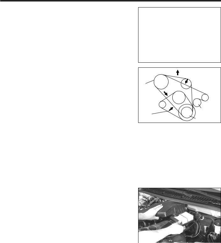
MA–6
MAINTENANCE OPERATION
ENGINE
COLD ENGINE OPERATION
1.Inspection of drive belt
(1)Visual inspection of drive belt
Visually check the belt for separation of the adhesive rubber above and below the core, core separation from the belt side, severed core, separation of the rib from the adhesive rubber, cracks or separation of the ribs, torn or worn ribs or cracks in the inner ridges of the ribs. Replace the drive belt, if necessary.
(2)Inspection of drive belt tension
Measure the amount of the drive belt deflection when the midpoint of the drive belt between the alternator and the water pump pulley or between the crankshaft pulley and vane pump pulley is pushed with a force of 98 N (10 kgf).
Specified Belt Deflection |
|
|
|
New Belt: |
Alternator and water pump |
4 |
- 5 mm |
|
Vane pump(Power steering) |
8 |
- 11 mm |
Used Belt: |
Alternator and water pump |
5 |
- 6 mm |
|
Vane pump(Power steering) |
11 - 14 mm |
|
If necessary, adjust the drive belt tension. (Refer to the EM or SR section.)
JMA00005-00001
Measuring section for tension and deflection  Idle pulley
 With air
Vane conditioner pump
pulley
|
Idle pulley |
When without |
Crank shaft |
air conditioner |
pulley |
|
JMA00006-00002 |
2.Inspection of air filter element
(1)Removal of air filter element q Unlock the four clips.
w Gradually open the air filter case cover.
CAUTION:
∙Do not open the air filter case cover beyond what is necessary to remove the air filter element. Failure to observe this caution may lead to disconnection of the rubber hoses.
|
e Take out the air filter element from the air filter |
|
|
JMA00007-00003 |
|
|
case. |
|
(2) |
Replacement of air filter element |
|
|
Replace the air filter element with a new one when the |
|
|
replacement time arrives. |
|
(3) |
Inspection of air filter element |
|
|
Visually inspect the air filter element for being exces- |
|
|
sively dirty, damage or oily. |
|
|
Replace the air filter element, if necessary. |
|
Downloaded from www.Manualslib.com manuals search engine
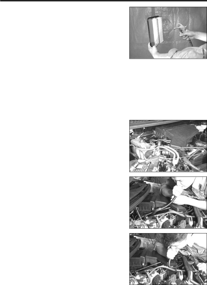
(4)Cleaning of air filter element
Clean the air filter element with compressed air.
First, blow compressed air from the back side of the element thoroughly. Then, blow off the upper side of the element.
WARNING:
∙Protect your eyes with safety goggles during the cleaning operation.
CAUTION:
∙The air pressure to be used for this cleaning operation should not exceed 392.3 kPa (4.0 kgf/cm2).
Replace the air filter element, if the element is excessively dirty.
(5)Installation of air filter element
q Install the air filter element in the air filter case cover.
NOTE:
∙Ensure that the air filter element faces in such a direction that the wider protrusion side comes to the air filter case cover side.
w Close the air filter case cover. e Latch the four clips properly.
3.Inspection of blow-by gas recirculation device
(1) Visually inspect the hoses for improper connections, cracks, leak and damage.
NOTE:
∙Replace parts which exhibit damage as necessary.
(2)Remove the oil filler cap.
(3)Disconnect the blow-by gas hose from the throttle body.
(4)Ensure that no resistance exists when you blow your breath to the disconnected hose end (which was connected to the throttle body).
If resistance is felt or no air continuity exists, check blow-by gas hose and the cylinder head cover.
(5)Connect the blow-by gas hose to the throttle body.
(6)Install the oil filler cap securely.
(7)Disconnect the PCV hose which is connected to the throttle body at the throttle body side.
(8)Ensure that heavy resistance exists when you blow your breath from the disconnected hose end.
If no continuity exists or no resistance for air continuity exists, replace or repair the cylinder head cover. (Refer to the EM section for the cylinder head cover replacement.)
NOTE:
∙The orifice is built in the cylinder head cover. This procedure is required for ensuring the orifice function in the cylinder head. If this orifice is plugged, correct engine idle speed will not be obtained.
(9) Connect the PCV hose to the throttle body properly.
MA–7
JMA00008-00004
JMA00009-00005
JMA00010-00006
JMA00011-00007
Downloaded from www.Manualslib.com manuals search engine
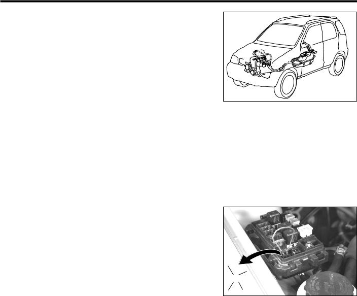
MA–8
4. Inspection of fuel line and connection
(1)Visually inspect the fuel line including the fuel hose for connecting condition, cracks, tightness, leakage and damage.
If cracks or any other damage exists, repair or replace the part as required.
(2) Check the connecting section of the fuel line for looseness and leakage.
If looseness or leakage exists on the connected sections of the fuel line, repair or replace the parts as required.
(3)Ensure that the ignition switch is turned OFF.
(4)Open the relay box cover in the engine compartment.
(5)Remove the fuel pump relay from the relay box.
CAUTION:
∙ Prevent dust or water, etc. from entering the connector. Entering of dust, water or contamination of the terminals in the fuel pump relay connector may cause fuel pump malfunction or other serious malfunctions, due to lowered insulation of each terminal.
(6)Connect the No. 1 and No. 2 terminals of the fuel pump relay in the relay box with suitable wires or the like as shown.
CAUTION:
∙Never deform or damage the terminals during the con-
|
nection. |
|
|
|
|
|
|
∙ |
Never make connection on a terminal except for those |
q |
|||||
|
specified. |
|
|
|
|
w |
|
|
|
|
|
|
|
||
|
Even slight contact of the other terminal causes serious |
|
|
|
|
|
|
|
|
|
|
|
|
||
|
trouble. |
|
|
|
|
|
|
|
e r |
||||||
∙ |
Prevent dust or water, etc. from entering the relay box. |
||||||
|
|
|
|
|
|||
Entering of dust, water or contamination of the terminals in the relay box causes serious malfunction, due to lowered insulation of each terminal.
(7)Turn ON the ignition switch.
(8)Ensure that no fuel leakage exists on the fuel line.
If fuel leakage exists, repair or replace the part as required.
(9)Turn OFF the ignition switch.
JMA00012-00008
JMA00013-00009
Downloaded from www.Manualslib.com manuals search engine
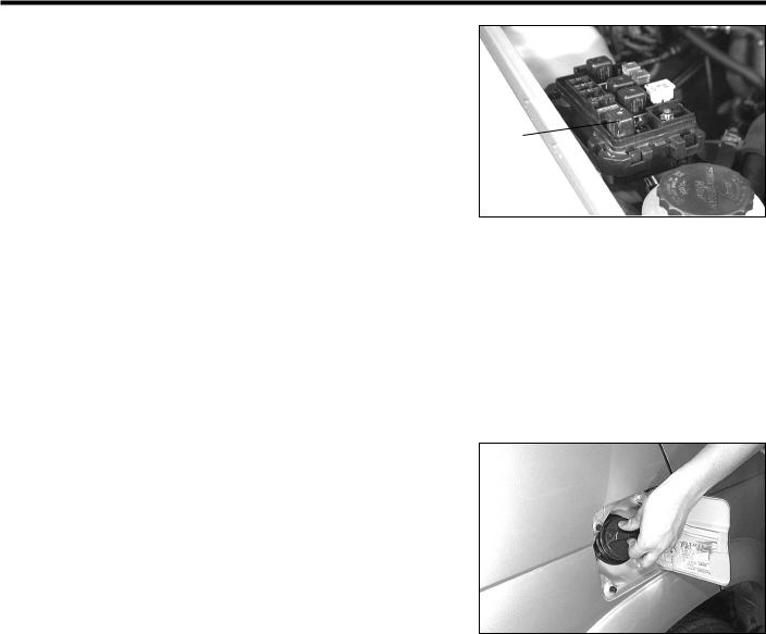
MA–9
(10)Remove the wire from the fuel pump relay terminal in the relay box.
CAUTION:
∙Never deform or damage the terminals during opera-
tion. |
|
∙ Never make connection between terminals except for |
|
those specified. |
|
Fuel pump |
|
Even slight contact of the other terminal causes serious |
relay |
trouble. |
|
∙Prevent dust or water, etc. from entering the relay box. Entering of dust, water or contamination of the terminals in the relay box causes serious malfunction, due to lowered insulation of each terminal.
(11)Install the fuel pump relay into the relay box.
(12)Close the relay box cover.
5.Replacement of fuel filter
WARNING:
∙Never smoke or work near open flame. Failure to observe this warning will cause fire.
Removal
(1)Ensure that the ignition switch is turned OFF.
(2)Open the fuel filler cap to release the inner pressure of the fuel tank.
(3)Remove the fuel pump relay from the relay box in the engine compartment. (See illustration above.)
CAUTION:
∙Never make connection on a terminal except for those specified.
Even slight contact of the other terminal causes serious trouble.
∙Prevent dust or water, etc. from entering the relay box. Entering of dust, water or contamination of the terminals in the relay box causes serious malfunction, due to lowered insulation of each terminal.
JMA00014-00010
JMA00015-00011
JMA00016-00000
Downloaded from www.Manualslib.com manuals search engine

MA–10
(4)Start the engine and wait for a little while until the engine stops.
(5)Turn off the ignition switch.
(6)Jack-up the vehicle and support it with safety stands. (Refer to the GI section.)
(7)Detach the fuel hose clips.
WARNING:
∙Never reuse the used hose clips. Failure to observe this warning may lead to fire.
(8)Disconnect the fuel hoses from the fuel filter and plug the disconnected hoses and fuel pipes of the fuel filter with a suitable plug or the like.
CAUTION:
∙Quite a large amount of fuel will flow out during fuel hose disconnection. Therefore, be sure to plug the disconnected hose and pipes properly.
(9)Remove the fuel filter from the fuel filter clamp.
Installation
(1)Install the fuel filter to the fuel filter clamp as shown.
CAUTION:
∙Be sure to install the fuel filter in such direction that the “IN” mark of fuel filter faces to fuel pump side and “OUT” mark faces to fuel pump side.
∙Failure to observe this caution may lead to fuel filter malfunction.
(2)Insert new hose clips to the fuel hoses.
(3)Connect the fuel hoses to the fuel filter until the fuel hose end comes in contact with the fuel filter body .
(4)Place the new fuel hose clips at each point between the pipe end and the spool. Then remove the clip holder to secure the fuel hoses.
CAUTION :
∙Never reuse the used hose clips.
(5)Install the fuel filler cap.
(6)Checking of fuel leakage
Perform the inspection described in the “Inspection of fuel line and connection”.
6.Inspection of charcoal canister
(1)Removal of charcoal canister
q Detach the hose bands from the hoses connected to the charcoal canister.
CAUTION:
∙Never reuse the removed hose bands.
wDisconnect the rubber hoses from the upper side of the charcoal canister.
NOTE:
∙Prior to the disconnection of the rubber hoses, put a tag on each of the rubber hoses so that they may be reconnected correctly to the original position.
JMA00017-00012
Engine side |
Fuel pump side |
|
JMA00018-00013
Charcoal canister
JMA00019-00014
Downloaded from www.Manualslib.com manuals search engine
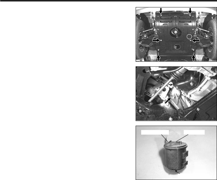
MA–11
eRemove the engine undercover by removing the six attaching bolts.
rDisconnect the atmosphere side hose from the frame.
tRemove the charcoal canister from the vehicle by pulling up the charcoal canister case to unlock it from the bracket.
yRemove the atmosphere side hose from the charcoal canister.
(2)Inspection of charcoal canister
q Visually inspect the charcoal canister case for cracks or damage. If any damage is found, replace the charcoal canister with a new one.
w Check the charcoal canister for air leakage. Ensure that no air leakage exceeding 0.3 ml/min is present
when applying compressed air of 29.4 kPa (0.3 kgf/cm2) into the fuel tank side pipe B with the throttle body side A and atmosphere side C pipes plugged.
If air leakage exceeding the above-specified value is present, replace the charcoal canister with a new one.
eEnsure that no air continuity exists when you blow into the purge side A pipe of the charcoal canister. If air continuity exists, replace the charcoal canister with a new one.
rCheck of charcoal canister for restriction
a.Ensure that air continuity exists to the atmosphere side C pipe, when you blow into the fuel tank side pipe B while the purge side A pipe is plugged.
If no air continuity exists, replace the charcoal canister with a new one.
b.Ensure that air continuity exists when applying a negative pressure to the purge side pipe A by a MityVac.
If no air continuity exists, replace the charcoal canister with a new one.
JMA00020-00015
JMA00021-00016
A Throttle body |
B Fuel tank |
C Atmosphere
JMA00022-00017
Downloaded from www.Manualslib.com manuals search engine

MA–12
tCleaning of charcoal canister
Clean the charcoal canister by blowing com-
pressed air of 294.2kPa (3.0 kg/cm2) into the fuel tank side pipe B while holding the purge side of the canister pipes A closed.
CAUTION:
∙Never attempt to wash the charcoal canister.
No activated carbon should come out during the test.
If activated carbon comes out, replace the charcoal canister.
(3)Installation of charcoal canister
The installation procedure is basically reverse to the removed procedure. Therefore, no illustration is given in this installation procedure.
q Install the charcoal canister to the charcoal canister holder and lock it securely.
w Connect the atmosphere side hose to the charcoal canister.
e Install the engine undercover with the six attaching bolts and tighten them securely.
rConnect the rubber hoses and attach new hose bands.
CAUTION:
∙Never reuse the removed hose band.
7.Replacement of evaporative emission control hose
Replace the fuel evaporative emission control hoses with new ones when the replacement interval arrives.
WARNING :
∙Replace the hose bands and clips with new ones. Never reuse the removed hose bands and clips.
JMA00023-00000
JMA00024-00018
JMA00025-00019
JMA00026-00020
JMA00027-00021
Downloaded from www.Manualslib.com manuals search engine
 Loading...