


FOREWORD
This is a revised version of the Daihatsu PDI (Pre-Delivery Inspection) manual in which the PDI items of those functions peculiar to the Copen are described in line with the introduction of the Copen to the market.
In as much as the contents of this manual can apply to all destination specifications and all models, including the options, it is unnecessary to carry out the checks for all equipment and functions that are posted in this manual.
When you perform the PDI operations, please refer to the relevant owners’ manual and service manual, as required, so as to confirm the specifications of the vehicle on which you are now working.
Revision 1: Published in September, 2003
No. 9807
2003 


All rights reserved. This material may not be reproduced or copied, in whole or in part, without the written permission of Daihatsu Motor Co., LTD.

TO INDEX
L2 MULTIPLEX COMMUNICATION SYSTEM
CAN COMMUNICATION SYSTEM ------------ |
L2 - 1 |
|
|
OUTLINE ----------------------------------------- |
L2 - 1 |
|
|
DESCRIPTION ------------------------------- |
L2 - 1 |
|
|
SYSTEM DRAWING ----------------------- |
L2 - 1 |
|
|
SYSTEM WIRING DIAGRAM ------------ |
L2 - 3 |
|
|
LOCATION OF COMPONENTS --------- |
L2 - 8 |
|
|
CONTROL---------------------------------------- |
L2 - 9 |
|
|
COMMUNICATION CONTROL ---------- |
L2 - 9 |
|
|
COMMUNICATION PROTOCOL ------ |
L2 - 10 |
|
|
COMMUNICATION DATA---------------- |
L2 - 10 |
|
|
DIAGNOSIS (SELF-DIAGNOSIS) |
L2 - 11 |
|
|
FUNCTION----------------------------------- |
|
||
FAIL-SAFE CONTROL ------------------- |
L2 - 11 |
|
|
COMPONENTS ------------------------------- |
L2 - 12 |
|
|
DLC -------------------------------------------- |
L2 - 12 |
|
|
TERMINATING RESISTANCE --------- |
L2 - 12 |
|
|
LIN COMMUNICATION SYSTEM ------------ |
L2 - 13 |
|
|
OUTLINE---------------------------------------- |
L2 - 13 |
|
|
DESCRIPTION ----------------------------- |
L2 - 13 |
|
|
SYSTEM DRAWING --------------------- |
L2 - 13 |
|
|
SYSTEM WIRING DIAGRAM ---------- |
L2 - 14 |
|
|
LOCATION OF COMPONENTS ------- |
L2 - 16 |
|
|
CONTROL |
L2 - 17 |
|
|
L2 |
|||
COMMUNICATION CONTROL -------- |
L2 - 17 |
||
---------WAKE-UP/SLEEP FUNCTION |
L2 - 17 |
|
|
LIN COMMUNICATION PROTOCOL |
L2 - 18 |
|
|
(COMMUNICATION REGULATION) -- |
|
||
DIAGNOSIS (ONBOARD |
L2 - 18 |
|
|
DIAGNOSIS FUNCTION)---------------- |
|
||
FAIL-SAFE FUNCTION ------------------ |
L2 - 18 |
|

L2–1
ÄCAN COMMUNICATION SYSTEM
1 OUTLINE
1-1 DESCRIPTION
1.A CANŕg,DK_Mŧ communication system which controls data relating to the power train at a higher speed is used in all vehicles.
2.The CAN system sends over a single communications line (twisted pair cable) multiple items of information and data which have been converted into digital form by a communication circuit.
This system reduces the number of the wiring harnesses and the size of the electronic control system for the systems that connect the input side (sensors, switches, etc.), the control units and the output side (display lamps, etc.).
3.The CAN communication system in use is a daisy chain type network with several computers connected to a pair of communication lines.
NOTE
• ~1:CAN stands for Controller Area Network. It is the serial communication based on the ISO standard (ISO011898).
1-2 SYSTEM DRAWING
1-2-1 RHD VEHICLES
ABS actuator |
|
Transmission |
|
Engine control |
|
|
|
|
|
control computer |
|
computer |
|
Meter |
|
|
|
(ABS ECU) |
|
(A/T ECU) |
|
(EFI ECU) |
|
(Meter ECU) |
|
DLC |
|
|
|
|
|
|
|
|
|
T11E1201ES24

|
|
|
|
|
|
|
|
|
L2–2 |
|
CAN communication connection system (RHD vehicles) |
|
|
|
|
|
|||||
|
|
|
|
ABS ECU |
A/T ECU |
EFI ECU |
Meter ECU |
DLC |
Name of |
|
|
|
|
|
|
|
|
|
|
CAN com- |
|
|
|
|
|
|
|
|
|
|
munication |
|
|
|
|
|
|
|
|
|
|
system type |
|
|
1KR |
M/T |
Vehicles not |
( |
( |
< |
< |
< |
Type 1 |
|
|
|
|
equipped with ABS |
|
|
|
|
|
|
|
|
|
|
ABS-equipped vehi- |
< |
( |
< |
< |
< |
Type 2 |
|
|
|
|
cles |
|
|
|
|
|
|
|
|
K3 |
M/T |
Vehicles not |
( |
( |
< |
< |
< |
Type 1 |
|
|
|
|
equipped with ABS |
|
|
|
|
|
|
|
|
|
|
ABS-equipped vehi- |
< |
( |
< |
< |
< |
Type 2 |
|
|
|
|
cles |
|
|
|
|
|
|
|
|
|
A/T |
Vehicles not |
( |
< |
< |
< |
< |
Type 3 |
|
|
|
|
equipped with ABS |
|
|
|
|
|
|
|
|
|
|
ABS-equipped vehi- |
< |
< |
< |
< |
< |
Type 4 |
|
|
|
|
cles |
|
|
|
|
|
|
|
1-2-2 |
LHD VEHICLES |
|
|
|
|
|
ABS actuator |
Transmission control |
Meter |
Engine control |
|
|
(ABS ECU) |
computer (A/T ECU) |
(Meter ECU) |
computer (EFI ECU) |
DLC |
|
|
|
|
|
T11E1711ES24 |

L2–3
CAN communication connection system (LHD vehicles)
|
|
|
ABS ECU |
A/T ECU |
Meter ECU |
EFI ECU |
DLC |
Name of |
|
|
|
|
|
|
|
|
CAN com- |
|
|
|
|
|
|
|
|
munication |
|
|
|
|
|
|
|
|
system type |
1KR |
M/T |
Vehicles not |
( |
( |
< |
< |
< |
Type 5 |
|
|
equipped with ABS |
|
|
|
|
|
|
|
|
ABS-equipped vehi- |
< |
( |
< |
< |
< |
Type 6 |
|
|
cles |
|
|
|
|
|
|
K3 |
M/T |
Vehicles not |
( |
( |
< |
< |
< |
Type 5 |
|
|
equipped with ABS |
|
|
|
|
|
|
|
|
ABS-equipped vehi- |
< |
( |
< |
< |
< |
Type 6 |
|
|
cles |
|
|
|
|
|
|
|
A/T |
Vehicles not |
( |
< |
< |
< |
< |
Type 7 |
|
|
equipped with ABS |
|
|
|
|
|
|
|
|
ABS-equipped vehi- |
< |
< |
< |
< |
< |
Type 8 |
|
|
cles |
|
|
|
|
|
|
1-3 SYSTEM WIRING DIAGRAM
1-3-1 |
RHD VEHICLES |
|
|
|
|
|
|
(1) Type 1 |
|
|
|
|
|
|
|
|
Engine control |
|
|
|
|
DLC |
|
|
|
Meter (Meter ECU) |
|
||||
|
computer (EFI ECU) |
|
|||||
|
|
|
|
|
|||
|
CANH |
|
HCAN |
CANH |
|
HCAN |
CANH |
|
|
|
|
|
|
|
|
|
CAN |
|
|
CAN |
|
|
|
|
transceiver |
|
transceiver |
|
|
||
|
CANL 'B |
E1 |
LCAN |
CANL 'B |
GND |
LCAN |
CANL |
|
|
||||||
|
|
|
Terminating resistance |
|
Terminating resistance |
||
|
|
|
(60+) |
|
|
(60+) |
|
|
|
Main relay |
|
|
|
|
|
|
|
EFI |
|
|
BACK UP |
|
|
|
F/L |
|
|
|
|
|
|
|
Battery |
|
|
|
|
|
|
|
|
|
|
|
|
|
T11E1712ES22 |

L2–4
(2) Type 2
ABS actuator |
Engine control |
|
|
Meter |
|
DLC |
(ABS ECU) |
computer (EFI ECU) |
|
(Meter ECU) |
|
|
|
HCAN |
CANH |
HCAN |
CANH |
|
HCAN |
CANH |
|
|
|
|
|
|
|
|
CAN |
|
|
|
CAN |
|
|
CAN |
|
|
|
transceiver |
|
|
transceiver |
|
transceiver |
|
|
||||
GND |
'IG |
LCAN |
|
|
CANL 'B |
E1 |
LCAN |
CANL 'B |
GND |
LCAN |
CANL |
|
|
|
|||||||||
|
|
ECU IG1 |
|
|
|
|
Terminating resistance |
|
Terminating resistance |
||
|
|
|
|
|
|
(60+) |
|
|
(60+) |
|
|
|
|
|
|
|
|
|
|
|
|
||
|
|
IG1 SW |
|
|
|
Main relay |
|
|
|
|
|
|
|
AM1 F/L |
|
|
|
EFI |
|
|
BACK UP |
|
|
|
|
F/L |
|
|
|
|
|
|
|
|
|
|
|
Battery |
|
|
|
|
|
|
|
|
|
|
|
|
|
|
|
|
|
|
|
|
T11E1713ES22 |
(3) Type 3 |
|
|
|
|
|
|
|
|
|
|
|
|
|
Transmission control |
Engine control |
|
|
Meter |
|
DLC |
|||
|
|
computer (A/T ECU) |
computer (EFI ECU) |
(Meter ECU) |
|
|
|||||
|
|
CANH |
|
HCN1 |
CANH |
|
HCAN |
CANH |
|
HCAN |
CANH |
|
|
|
|
|
|
|
|
|
|
|
|
|
|
|
CAN |
|
CAN |
|
|
CAN |
|
|
|
|
|
transceiver |
transceiver |
|
transceiver |
|
|
||||
|
|
CANL |
'B1 E1 |
LCN1 |
CANL 'B |
E1 |
LCAN |
CANL 'B |
GND |
LCAN |
CANL |
|
|
|
|||||||||
|
|
ECU IG2 |
|
|
|
|
Terminating resistance |
|
Terminating resistance |
||
|
|
|
|
|
|
(60+) |
|
|
(60+) |
|
|
|
|
|
|
|
|
|
|
|
|
||
|
|
IG2 SW |
|
|
|
Main relay |
|
|
|
|
|
|
|
AM2 F/L |
|
|
|
EFI |
|
|
BACK UP |
|
|
|
|
F/L |
|
|
|
|
|
|
|
|
|
|
|
Battery |
|
|
|
|
|
|
|
|
|
|
|
|
|
|
|
|
|
|
|
|
T11E1714ES22 |

L2–5
(4) Type 4
ABS actuator |
Transmission control |
Engine control |
|
|
Meter |
|
DLC |
||
(ABS ECU) |
computer (A/T ECU) |
computer (EFI ECU) |
(Meter ECU) |
|
|
||||
HCAN |
CANH |
HCN1 |
CANH |
|
HCAN |
CANH |
|
HCAN |
CANH |
|
|
|
|
|
|
|
|
|
|
CAN |
CAN |
|
CAN |
|
|
CAN |
|
|
|
transceiver |
transceiver |
transceiver |
|
|
transceiver |
|
|
||
GND 'IG LCAN |
CANL 'B1 E1 |
LCN1 |
CANL 'B |
E1 |
LCAN |
CANL 'B |
GND |
LCAN |
CANL |
|
|||||||||
|
ECU IG1 |
ECU IG2 |
|
Terminating resistance |
|
Terminating resistance |
||
|
|
(60+) |
|
|
(60+) |
|
||
|
|
|
|
|
|
|
||
|
IG1 SW |
IG2 SW |
Main relay |
|
|
|
|
|
|
AM1 F/L |
AM2 F/L |
EFI |
|
|
BACK UP |
|
|
|
F/L |
|
|
|
|
|
|
|
|
Battery |
|
|
|
|
|
|
|
|
|
|
|
|
|
|
|
T11E1715ES22 |
1-3-2 |
LHD VEHICLES |
|
|
|
|
|
|
|
(1) Type 5 |
|
|
|
|
|
|
|
|
|
|
|
Meter |
|
Engine control |
|
DLC |
|
|
|
(Meter ECU) |
|
|
|
|||
|
|
|
computer (EFI ECU) |
|
||||
|
|
|
|
|
|
|||
|
|
CANH |
|
HCAN |
CANH |
|
HCAN |
CANH |
|
|
|
|
|
|
|
|
|
|
|
CAN |
|
CAN |
|
|
|
|
|
|
transceiver |
|
transceiver |
|
|
||
|
|
CANL 'B |
GND |
LCAN |
CANL 'B |
E1 |
LCAN |
CANL |
|
|
|
||||||
|
|
|
|
Terminating resistance |
|
Terminating resistance |
||
|
|
|
|
(60+) |
|
|
(60+) |
|
|
|
|
|
|
|
Main relay |
|
|
|
|
|
BACK UP |
|
EFI |
|
|
|
|
F/L |
|
|
|
|
|
|
|
|
Battery |
|
|
|
|
|
|
|
|
|
|
|
|
|
|
|
T11E1716ES22 |

L2–6
(2) Type 6
ABS actuator |
|
Meter |
|
Engine control |
|
DLC |
|
(ABS ECU) |
(Meter ECU) |
computer (EFI ECU) |
|
||||
HCAN |
CANH |
|
HCAN |
CANH |
|
HCAN |
CANH |
|
|
|
|
|
|
|
|
CAN |
CAN |
|
|
CAN |
|
|
|
transceiver |
transceiver |
|
transceiver |
|
|
||
GND 'IG LCAN |
CANL 'B |
GND |
LCAN |
CANL 'B |
E1 |
LCAN |
CANL |
|
|||||||
ECU IG1 |
|
|
Terminating resistance |
|
Terminating resistance |
||
|
|
(60+) |
|
|
(60+) |
|
|
|
|
|
|
|
|
||
IG1 SW |
|
|
|
|
Main relay |
|
|
AM1 F/L |
|
|
|
BACK UP |
|
EFI |
|
|
|
F/L |
|
|
|
|
|
|
|
|
|
Battery |
|
|
|
|
|
|
|
|
|
|
|
|
|
|
|
|
|
|
T11E1717ES22 |
(3) Type 7 |
|
|
|
|
|
|
|
|
|
Transmission control |
|
Meter |
|
Engine control |
|
DLC |
|||
computer (A/T ECU) |
(Meter ECU) |
|
computer (EFI ECU) |
|
|||||
CANH |
|
HCN1 |
CANH |
|
HCAN |
CANH |
|
HCAN |
CANH |
|
|
|
|
|
|
|
|
|
|
|
CAN |
|
CAN |
|
|
CAN |
|
|
|
transceiver |
|
transceiver |
|
transceiver |
|
|
|||
CANL |
'B1 E1 |
LCN1 |
CANL 'B |
GND |
LCAN |
CANL 'B |
E1 |
LCAN |
CANL |
|
|||||||||
ECU IG2 |
|
|
|
|
Terminating resistance |
|
Terminating resistance |
||
|
|
|
|
(60+) |
|
|
(60+) |
|
|
|
|
|
|
|
|
|
|
||
IG2 SW |
|
|
|
|
|
|
Main relay |
|
|
AM2 F/L |
|
|
|
BACK UP |
|
|
EFI |
|
|
F/L |
|
|
|
|
|
|
|
|
|
Battery |
|
|
|
|
|
|
|
|
|
|
|
|
|
|
|
|
|
|
T11E1718ES22 |

L2–7 |
|
|
|
|
|
|
|
|
|
|
|
|
(4) Type 8 |
|
|
|
|
|
|
|
|
|
|
|
|
|
ABS actuator |
Transmission control |
|
Meter |
|
Engine control |
|
DLC |
||||
|
(ABS ECU) |
computer (A/T ECU) |
(Meter ECU) |
|
computer (EFI ECU) |
|
||||||
|
|
HCAN |
CANH |
|
HCN1 |
CANH |
|
HCAN |
CANH |
|
HCAN |
CANH |
|
|
|
|
|
|
|
|
|
|
|
|
|
|
CAN |
|
|
CAN |
|
CAN |
|
CAN |
|
|
|
|
transceiver |
|
transceiver |
transceiver |
|
transceiver |
|
|
|||||
GND |
'IG |
LCAN |
CANL |
'B1 E1 |
LCN1 |
CANL 'B |
GND |
LCAN |
CANL 'B |
E1 |
LCAN |
CANL |
|
||||||||||||
|
|
ECU IG1 |
ECU IG2 |
|
|
|
|
Terminating resistance |
|
Terminating resistance |
||
|
|
|
|
|
|
(60+) |
|
|
(60+) |
|
||
|
|
|
|
|
|
|
|
|
|
|
||
|
|
IG1 SW |
IG2 SW |
|
|
|
|
|
|
Main relay |
|
|
|
|
AM1 F/L |
AM2 F/L |
|
|
|
BACK UP |
|
|
EFI |
|
|
|
|
F/L |
|
|
|
|
|
|
|
|
|
|
|
|
Battery |
|
|
|
|
|
|
|
|
|
|
|
|
|
|
|
|
|
|
|
|
|
|
T11E1719ES22 |

L2–8
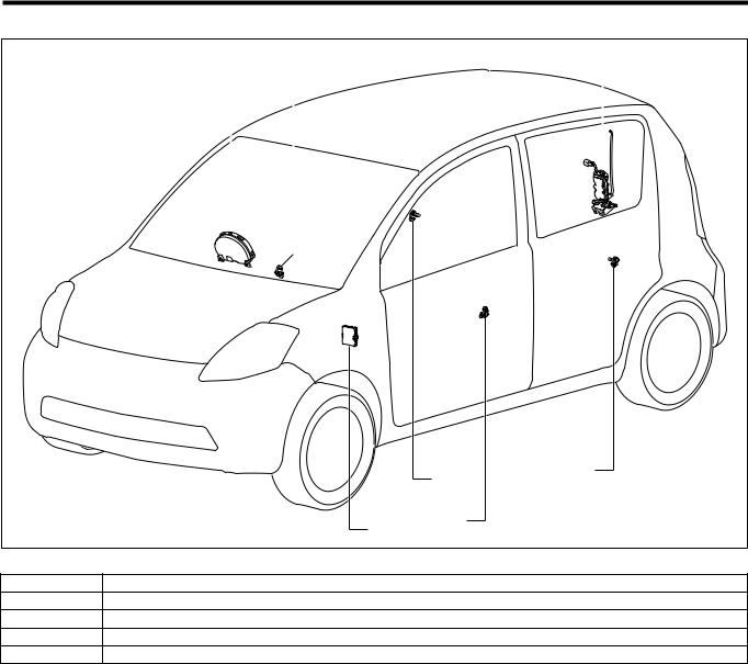
1-4 LOCATION OF COMPONENTS
b |
d |
|
a
e |
c |
T11E1203S30
The illustration show a right-hand drive vehicle.
Part name
aDLC
bMeter (meter ECU)
cEngine control computer (EFI ECU)
dTransmission control computer (A/T ECU)
eABS actuator (ABS ECU)
L2–9
2 CONTROL
2-1 COMMUNICATION CONTROL
1. A CAN communication system has two communication lines (bus) acting as a pair and the bus level ŕg,DK_Mŧŕg,DK_Mŧ is determined by the voltage differential between them. The two lines are called CAN high (CANH) and CAN low (CANL) respectively. Data is transmitted at the rate of 500kbps ŕg,DK_Mŧ as a digital signal according to the CAN dedicated communication protocol.
NOTE
•~2: The bus level has a dominant level and a recessive level. CAN communication system logic deems dominant to be 808 and recessive to be 818.
•~3: The signal rate of data transmission is expressed in bits per second (bps). 8500kbps8 means that 500,000 bits of data are transmitted per second.
ECU
transceiver CAN
CANH |
CANH |
CANL |
CANL |
|
|
|
"Outline of CAN |
|
communication system wiring" |
ECU
transceiver CAN
Voltage[V]
|
4 |
|
|
|
|
|
|
|
|
|
|
|
3 |
|
|
|
|
|
|
|
|
|
|
|
2 |
|
|
|
|
|
|
|
|
|
|
|
1 |
|
|
|
Passing of time |
|
|
|
|
||
|
0 |
|
|
|
|
|
|
|
|
(Communication |
|
|
|
|
|
|
|
Bus level |
|
Recessive Dominant |
Recessive Dominant |
Recessive speed 500kbps) |
|
HI="1"
LO="0"
"Differential voltage and physical layer of CAN bus system"
:CAN High
:CAN Low
mB11E1204ES24

L2–10
2-2 COMMUNICATION PROTOCOL
1.The CAN communication system is a multiplex systems in which all the ECU's in the network use a pair of communication lines (bus). Any of the ECU's can transmit data if the CAN bus is in an idol (open) state. Therefore, each ECU performs the communication according to the common communication protocol so that the communication can be done smoothly and securely.
2.Under CAN communication protocol all the ECU's share a common pair of communication lines and have the right to start transmitting data. CSMA/CD (Carrier Sense Multiple Access / Collision
Detection) ŕg,DK_Mŧ is the protocol used for sending data to the communication line.
NOTE
•~4: CSMA/CD stands for Carrier Sense Multiple Access with Collision Detection. It is a communication access protocol where ECU's check the status of the communication line (carrier) and only if there is no other data flowing will they start to send data of their own. Further, in addition to this, if a collision of data is detected (i.e. with data that has been transmitted by another ECU at the same time), the offending ECU will wait for a fixed period of time and then resend the data.
3.ECU's start to transmit data when other data is not flowing in the CAN bus, but if two or more ECU's start to transmit data simultaneously then the priority of the data is determined by the ID which the transmitted data itself contains.
2-3 COMMUNICATION DATA
2-3-1 TYPE 1, TYPE 5
CAN communication signal
|
Nomenclature of signals |
|
Applicable ECU |
|
|
|
EFI ECU |
|
|
Meter ECU |
|
|
|
|
|
||
|
Engine coolant temperature |
. |
|
|
< |
|
Vehicle speed |
< |
|
|
. |
|
Tail switch |
< |
|
|
. |
|
.: signal sending, <:signal receiving |
|
|
|
|
2-3-2 TYPE 2, TYPE 6 |
|
|
|
|
|
CAN communication signal |
|
|
|
|
|
|
Nomenclature of signals |
|
Applicable ECU |
|
|
|
EFI ECU |
ABS ECU |
Meter ECU |
||
|
|
||||
|
Engine coolant temperature |
. |
( |
< |
|
|
Stop lamp switch |
( |
. |
( |
|
|
Vehicle speed |
< |
. |
< |
|
|
Brake warning lamp request |
( |
. |
< |
|
|
ABS warning lamp request |
( |
. |
< |
|
|
Running distance |
( |
. |
< |
|
|
ECU-T terminal |
( |
< |
. |
|
|
Tail switch |
< |
( |
. |
|
.: signal sending, <:signal receiving

L2–11
2-3-3 TYPE 3, TYPE 7
CAN communication signal
|
Nomenclature of signals |
|
|
Applicable ECU |
|
|||
|
EFI ECU |
|
A/T ECU |
|
Meter ECU |
|||
|
|
|
|
|||||
|
Throttle opening degree |
. |
|
|
< |
|
( |
|
|
Engine torque |
. |
|
|
< |
|
( |
|
|
Water temperature state |
. |
|
|
< |
|
( |
|
|
Engine coolant temperature |
. |
|
|
< |
|
< |
|
|
Request of deletion of MIL-related malfunction codes in A/T |
. |
|
|
< |
|
( |
|
|
Completion of deletion of MIL-related malfunction codes in |
< |
|
|
. |
|
( |
|
|
A/T |
|
|
|
|
|
|
|
|
Torque reduction request |
< |
|
|
. |
|
( |
|
|
Shift range information |
< |
|
|
. |
|
< |
|
|
O/D OFF lamp request |
( |
|
|
. |
|
< |
|
|
A/T warning request |
( |
|
|
. |
|
< |
|
|
A/T learning value erasure completion |
( |
|
|
. |
|
< |
|
|
Vehicle speed |
< |
|
|
. |
|
< |
|
|
ECU-T terminal |
( |
|
|
< |
|
. |
|
|
Tail switch |
< |
|
|
( |
|
. |
|
|
.: signal sending, <:signal receiving |
|
|
|
|
|
|
|
2-3-4 TYPE 4, TYPE 8 |
|
|
|
|
|
|
|
|
CAN communication signal |
|
|
|
|
|
|
|
|
|
Nomenclature of signals |
|
|
Applicable ECU |
|
|||
|
EFI ECU |
A/T ECU |
|
ABS ECU |
Meter ECU |
|||
|
|
|
||||||
|
Throttle opening degree |
. |
< |
|
( |
|
( |
|
|
Engine torque |
. |
< |
|
( |
|
( |
|
|
Water temperature state |
. |
< |
|
( |
|
( |
|
|
Engine coolant temperature |
. |
< |
|
( |
|
< |
|
|
Request of deletion of MIL-related malfunction codes in A/T |
. |
< |
|
( |
|
( |
|
|
Completion of deletion of MIL-related malfunction codes in |
< |
. |
|
( |
|
( |
|
|
A/T |
|
|
|
|
|
|
|
|
Torque reduction request |
< |
. |
|
( |
|
( |
|
|
Shift range information |
< |
. |
|
( |
|
< |
|
|
O/D OFF lamp request |
( |
. |
|
( |
|
< |
|
|
A/T warning request |
( |
. |
|
( |
|
< |
|
|
A/T learning value erasure completion |
( |
. |
|
( |
|
< |
|
|
Stop lamp switch |
( |
< |
|
. |
|
( |
|
|
Vehicle speed |
< |
< |
|
. |
|
< |
|
|
Brake warning lamp request |
( |
( |
|
. |
|
< |
|
|
ABS warning lamp request |
( |
( |
|
. |
|
< |
|
|
Running distance |
( |
( |
|
. |
|
< |
|
|
ECU-T terminal |
( |
< |
|
< |
|
. |
|
|
Tail switch |
< |
( |
|
( |
|
. |
|
.: signal sending, <:signal receiving
2-4 DIAGNOSIS (SELF-DIAGNOSIS) FUNCTION
Diagnostics means failure diagnosis. This is a function by which if there are any abnormalities in the input signal the ECU will inform a mechanic/technician of the abnormal item.
CAN communication failure diagnosis sets up a separate diagnosis code for each ECU which constitutes the CAN.
Please refer to the repair/maintenance manual for details of the failure diagnosis function.
2-5 FAIL-SAFE CONTROL
If the CAN communication system continues operating in the event of abnormalities such as open wires or short circuits in the CAN communication line and communication abnormality between ECU's, there may be the possibility that the abnormalities may effect the control of each system. Under these circumstances each ECU will come under the control of a preset internal control system.
For details of the fail-safe controls please refer to the item of each system which makes up the CAN.

L2–12
3 COMPONENTS
3-1 DLC
A DLC (Data Link Connector) is installed forward of the driver's seat (lower portion of the instrument panel, driver's seat door side).
CANH and CANL terminals have been added to the DLC with the adoption of a CAN communication system.
CANL
1 |
2 |
3 |
4 |
5 |
6 |
7 |
8 |
9 |
10 |
11 |
12 |
13 |
14 |
15 |
16 |
CANH
DLC
T11E1206S16
3-2 TERMINATING RESISTANCE
The terminating resistance is located in the combination meter and in the engine control computer.
As the terminating resistance, there are two 60 + resistors in series. As a result, the differential voltage can be judged from the loop connected network.

L2–13
ÄLIN COMMUNICATION SYSTEM
1 OUTLINE
1-1 DESCRIPTION
1.All vehicles are equipped with LIN communication (LIN: Local Interconnect Network) *. 2.The LIN communication consists of the meter ECU and ITC.
3.Multiplex communication is a system in which plural ECU's are connected to a single communication line to provide mutual data exchange. This has made it possible to integrate the system and prevent the number of wires from increasing when a function is added.
4.Controls actually taking place in the multiplex communications are the wake-up/sleep controls, system controls by applicable ECU and so forth.
5.A diagnosis function is provided that will inform the operator of any abnormality of the system. Also, fail-safe functions are provided that will assure the minimum functions for each ECU and protect the systems when abnormal communications occur between the ECUs.
6.The communication method employs a single master system in which the meter ECU controls the sleep (low current mode), wake-up (standby mode), etc. of the communication applicable ECU.
NOTE
•*: The LIN communication is a multiplex communication network mainly intended for the data communications between the body-related control ECUs.
1-2 SYSTEM DRAWING
The LIN communication consists of the meter ECU and ITC.
Meter ECU |
|
ITC |
|
|
|
B11H1022ET10

L2–14
1-3 SYSTEM WIRING DIAGRAM
|
|
|
|
|
|
Fuse block |
|
|
|
|
|
|
|
|
|
|
IG1/BACK 7 |
IG1 |
|
|
|
|
|
|
|
|
|
|
|
D/LOCK |
|
|
|
|
|
|
|
|
|
|
|
|
17 BDR1 |
|
ITC |
|
|
|
|
|
|
|
|
IG SW |
|
|
|
|
|
|
|
|
|
|
|
|
ACC |
|
|
|
|
|
|
|
|
|
|
|
AM1 |
|
|
|
|
GND |
MPX |
|
|
|
|
|
|
|
IG1 |
9 |
ECUB |
|
|
|
|
|
|||
|
|
|
|
|
|
1 |
6 |
|
|
|
|
|
|
|
|
IG2 |
|
|
|
|
|
|
|
||
F/L |
AM2 |
|
|
|
|
|
LIN wire |
|
|
|
|
|
|
ST |
|
|
|
|
|
|
|
|
|||
|
|
|
|
ECU IG2 |
|
|
communication |
|
|
|
|
|
|
|
|
|
|
|
|
|
|
|
|
||
|
IG1 |
|
|
|
|
|
|
|
|
|
|
|
|
|
|
|
|
|
|
|
|
|
|
|
|
|
BACK UP |
|
|
|
|
9 |
|
20 |
|
|
|
|
|
|
|
10 'B |
IG2 |
|
LIN |
|
|
|
|
||
|
|
|
|
|
|
|
|
|
||||
|
|
|
|
|
|
Combination meter |
|
|
|
|
||
|
|
|
|
|
|
GND |
ECU-T |
DOOR |
|
|
|
|
|
|
|
|
|
|
18 |
17 |
11 |
|
|
|
|
|
|
|
|
|
|
|
DLC |
right Front |
left Front |
right Rear |
left Rear |
BACK |
|
|
|
|
|
|
|
|
|||||
|
|
|
|
|
|
|
|
Courtesy switch |
|
|||
|
|
|
|
|
|
|
|
|
|
|
|
T11H1539ES25 |

L2–15
Arrangement of ECU terminal
1 |
2 |
3 |
4 |
5 |
6 |
7 |
8 |
9 |
10 |
11 |
12 |
13 |
14 |
15 |
16 |
17 |
18 |
|
|
|
|
|
|
|
|
|
|
|
|
|
|
|
|
|
|
ITC
|
|
|
|
|
|
|
|
|
|
|
|
|
|
|
|
|
|
|
|
|
|
|
|
|
|
|
|
|
|
|
|
|
|
|
|
|
|
|
|
|
|
|
|
|
|
|
|
|
|
|
|
|
|
|
|
|
20 |
19 |
18 |
17 |
16 |
15 |
14 |
13 |
12 |
11 |
10 |
9 |
8 |
7 |
6 |
5 |
4 |
3 |
2 |
1 |
|
||||||
|
|
|
|
|
|
|
|
|
|
|
|
|
|
|
|
|
|
|
|
|
|
|
|
|
|
|
|
|
40 |
39 |
38 |
37 |
36 |
35 |
34 |
33 |
32 |
31 |
30 |
29 |
28 |
27 |
26 |
25 |
24 |
23 |
22 |
21 |
|
||||||
|
|
|
|
|
|
|
|
|
|
|
|
|
|
|
|
|
|
|
|
|
|
|
|
|
|
|
|
|
|
|
|
|
|
|
|
|
|
|
|
|
|
|
|
|
|
|
|
|
|
|
|
|
|
|
|
|
|
|
|
|
|
|
|
|
|
|
|
|
|
|
|
|
|
|
|
|
|
|
|
|
|
|
|
Combination meter
T11H9502ES20
Meter terminal name (Multiplex communication system)
Terminal No. |
Terminal code |
Terminal name |
9 |
IG2 |
IG power supply |
10 |
+B |
'B power supply |
11 |
DOOR |
Input of courtesy switch signal |
17 |
ECU-T |
ECU-T terminal signal input |
18 |
GND |
Earth |
20 |
LIN |
LIN communication input/output |
ITC terminal name (Multiplex communication system)
Terminal No. |
Terminal code |
Terminal name |
1 |
GND |
Earth |
6 |
MPX |
Multiple communication input/output |
7 |
IG1 |
ECU power supply |
9 |
ECU B |
ECU power supply |
17 |
BDR1 |
Power supply |
L2–16
1-4 LOCATION OF COMPONENTS
a |
|
c |
|
|
|
e |
|
|
|
|
|||
|
|
|
|
|
|
|
|
|
|
|
|
|
|
|
|
|
|
|
|
|
d
d
b c
T11H1525S25
The illustration represents the RHD vehicle. In the case of the LHD vehicle, the combination meter is located at the left side.
aMeter ECU (inside the combination meter)
bITC
cFront door courtesy switch
dRear door courtesy switch
eBack door courtesy switch (inside the back door lock Ay)

L2–17
2 CONTROL
2-1 COMMUNICATION CONTROL
2-1-1 DESCRIPTION
The meter ECU controls the following items. 1.Evaluation of presence/non-presence of ECU 2.Communication start informing control 3.Wake-up/sleep control
2-1-2 EVALUATION OF PRESENCE/NON-PRESENCE OF ECU
The meter ECU detects the presence of the ECU every time the battery power supply is turned on. 1.When the LIN communication applicable ECU is not connected to the meter ECU, or when it does not
respond to the meter ECU due to failure, etc. of the LIN communication applicable ECU, the meter ECU transmits a command to other ECUs that have been judged to be present to perform such communication control that is to be carried out when the ECU that has made no response is not mounted (Evaluation of ECU non-presence).
2.The meter ECU, after detecting the presence of the ECU, continues to monitor ECU connecting status at constant intervals.
3.When the LIN communication applicable ECU responds properly to the meter ECU during the ECU presence/non-presence evaluation, or when the ECU that has made no response returns to the normal condition and makes a proper response after the ECU has been judged not to be present, the meter ECU transmits a command to other LIN communication applicable ECUs to perform such communication control that is to be carried out when the ECU that has made a response is mounted (Evaluation of ECU presence).
2-1-3 COMMUNICATION START CONTROL
The communication start is always started from the meter ECU. The signal of communication start is transmitted to other ECU.
2-1-4 WAKE-UP/SLEEP CONTROL
When transferring to the sleep (the low current mode), or transferring from the sleep (the low current mode) to the wake-up (the standby mode), the meter ECU transmits a transfer start command to the other LIN communication applicable ECUs, thereby transferring to the wake-up/sleep control.
2-2 WAKE-UP/SLEEP FUNCTION
2-2-1 DESCRIPTION
The LIN communication system is equipped with a wake-up/sleep function to reduce the current used when the IG switch is in the ACC and LOCK positions.
2-2-2 CONDITIONS FOR REALIZING SLEEP
When the following conditions 1 and 2, or the condition 3 is satisfied, the meter ECU sends a sleep command to each ECU, thus transferring to the sleep state (the low current mode).
1.The IG switch is set to the ACC position or the LOCK position.
2.The meter ECU received the information that the control of each ECU is complete, and the control of the meter itself is complete.
3.Ten minutes have passed after the IG switch was set to the ACC position or the LOCK position, with the door open (the battery discharging prevention function).
2-2-3 CONDITIONS FOR REALIZING WAKE-UP
When either of the following conditions is satisfied, the meter ECU sends a wake-up command to each ECU, thus transferring to the wake-up state (the standby mode).
1.Cases where there is a change in the data to be communicated at each ECU, and the ECU transmits a wake-up (the standby mode) signal to the meter ECU.
2.Cases where the IG switch is turned from the ACC or LOCK position to the ON position. 3.Immediately after connecting a battery.

L2–18
2-3 LIN COMMUNICATION PROTOCOL (COMMUNICATION REGULATION)
1.The LIN communication system is a two-way interactive time-division multiplexing communication system, where all ECUs that make up the network can send and receive data by delaying the timing for using a communication line in order to share a single communication line. Each ECU, therefore, communicates according to the common communication protocol (communication regulation) to ensure smooth and reliable communication.
2.The data used by the LIN communication system consist of digital signals that include information such as ID to identify each ECU (node ID) and contents of communication data.
3.In order for all ECUs to be able to communicate by sharing a single communication line, based on the specified transmission time schedule, the single master system is employed as a communication regulation for the communication line, in which the meter ECU controls the communication timing, sleep (the low current mode) and wake-up (the standby mode), etc. of the communication applicable ECU.
2-4 DIAGNOSIS (ONBOARD DIAGNOSIS FUNCTION)
This is a function whereby the ECU informs the inspection operator of the abnormal items when there has been a failure in the system. When failure takes place, the ECU memorizes the abnormal item.
Please refer to the repair manual for details concerning the diagnosis.
2-5 FAIL-SAFE FUNCTION
When communication remains unestablished between the applicable ECU and the meter ECU for a certain length of time, the predetermined control is performed by transferring to the fail-safe mode.
Conditions of each system during the fail-safe mode
Applicable ECU |
Condition |
|
;The keyless operation will not take place. |
ITC |
;The room lamp control will not take place. |
|
*: The power door locking operates normally. |
CAUTION
•When the meter ECU transfers to the fail-safe mode, the ITC, being unable to communicate with the meter ECU, will transfer to the fail-safe mode.
TO INDEX |
|
TO NEXT SECTION |
TO INDEX
K1 HEATER & AIR CONDITIONER
HEATER AND AIR CONDITIONER ----------- |
K1 - 1 |
|
|
OUTLINE ----------------------------------------- |
K1 - 1 |
|
|
CONSTRUCTION AND OPERATION ---- |
K1 - 4 |
|
|
REFRIGERANT------------------------------ |
K1 - 4 |
|
|
DISCHARGE PORT ------------------------ |
K1 - 4 |
|
|
CONTROL PANEL -------------------------- |
K1 - 5 |
|
|
HEATER CORE------------------------------ |
K1 - 5 |
|
|
EVAPORATOR ------------------------------- |
K1 - 6 |
|
|
COMPRESSOR ----------------------------- |
K1 - 6 |
|
|
CONDENSER -------------------------------- |
K1 - 6 |
|
|
MANUAL AIR CONDITIONER SYSTEM ---- |
K1 - 7 |
|
|
OUTLINE ----------------------------------------- |
K1 - 7 |
|
|
SYSTEM WIRING DIAGRAM------------ |
K1 - 7 |
|
|
LOCATION OF COMPONENTS--------- |
K1 - 9 |
|
|
LOCATION OF COMPONENTS ------- |
K1 - 11 |
|
|
CONTROL-------------------------------------- |
K1 - 13 |
|
|
AIR CONDITIONER CONTROL BY |
K1 - 13 |
|
|
ENGINE CONTROL COMPUTER ---- |
|
||
COMPONENTS ------------------------------- |
K1 - 14 |
|
|
ENGINE CONTROL COMPUTER ---- |
K1 - 14 |
|
|
BLOWER RESISTOR |
K1 - 14 |
|
|
K1 |
|||
PRESSURE SWITCH -------------------- |
K1 - 14 |
||
EVAPORATOR TEMPERATURE |
K1 - 15 |
|
|
SENSOR ------------------------------------- |
|
||
CONTROL PANEL ------------------------ |
K1 - 15 |
|

K1–1
ÄHEATER AND AIR CONDITIONER
1 OUTLINE
1.Some specifications have an air conditioner with manual controls. 2.A Three-dial control panel has been set.
3.The evaporator employs a small, lightweight type RS Evaporator (RS: Revolutionary Super Slim) which improves the evaporator's heat exchange efficiency when the air conditioner is running.
4.The heater core employs a small, lightweight SFA heater core @ (SFA: straight flow aluminum) which should give superior heat transmission performance when the system is heating.
5.The refrigerant HFC-134a (R-134a) that contains no chlorine has been adopted as the air conditioner refrigerant, taking into consideration the need to prevent ozone layer depletion.

K1–2
Front section (LHD vehicle)
Cooling unit
Compressor
Condenser
T11H1514ES20
The illustration shows a typical example.
Front section (RHD vehicle)
Air conditioner unit
Compressor
Condenser
T11H1023ES20
The illustration shows a typical example.

K1–3
Instrument panel section (LHD vehicle)
Front defroster
Side defroster
Center register
Side register
Heater unit
Cooling unit
T11H1515ES20
The illustration shows a typical example.
Instrument panel section (RHD vehicle)
Front defroster


 Center register
Side register
Air conditioner unit
T11H1516ES20
The illustration shows a typical example.

K1–4
2 CONSTRUCTION AND OPERATION
2-1 REFRIGERANT
The refrigerant HFC-134a (R-134a) that contains no chlorine has been adopted as the air conditioner refrigerant, taking into consideration the prevention of deletion of ozone layer.
2-2 DISCHARGE PORT
The air outlets are located in the center of the instrument panel, on both side-sections, on the defroster and on the leg sections of people sitting in front seats.
LHD vehicle |
RHD vehicle |
T11H1517ES20
Air outlets according to mode

K1–5
2-3 CONTROL PANEL
A three-dial type control panel is employed. The dial pointer adopts night illumination to assure easy operation and reading night time. The blower switch can be adjusted over four stages.
T11H1054S16
The illustration shows a typical example.
2-4 HEATER CORE
The heater core employs a small, lightweight SFA heater core @ (SFA: straight flow aluminum).
The SFA heater core @ is more compact than conventional SFA heater cores because of the reduction in tank width and height/miniaturization of the core (core area expansion). This has achieved increased air flow, noise reduction, and an improvement in heating capacity. The SFA heater core @ is constructed from tubes, fins and capsules and the result has been that by flattening the tubes the heat transfer rate has been improved as well as producing a lightweight, small size heater. Further, the use of aluminum makes the heater more environmentally friendly.
TubeQfin
Capsule
T11H1055ET16

K1–6
2-5 EVAPORATOR
The evaporator employs a small, lightweight type RS Evaporator (RS: Revolutionary Super Slim).
The RS evaporator consists of a tank, tubes and cooling fins. Thanks to the press molding of the tube, minute flow paths have been formed and this leads to improved heat transfer capability and very thin dimensions. Further, the RS evaporator has improved heat transfer due to the reduced fin height, tube thickness, and fin pitch, and the unit is much reduced in size and weight due to the reduced stock thickness of the core material. The evaporator is coated with a hydrophilic plastic film which contains anti-bac- teria agent to control the breeding of germs and bacteria which can lead to unpleasant smells. In consideration of the environment the surface treatment is chrome-free.
|
Tank |
Fine multi-hole tube |
|
|
|
|
|
|
|
|
|
Cooling fin |
Anti-bacteria agent is added to hydrophilic |
|
resin coating |
||
Tank |
Hydrophilic resin coating |
|
Chrome-free chemical conversion coating |
||
|
||
|
Aluminum base metal |
|
|
T11H1056ES16 |
2-6 COMPRESSOR
Vane type compressor is employed.
2-7 CONDENSER
A new type of sub cooling condenser is used which has improved performance with its miniaturized core and an increased effective surface area, compared with the conventional ones. Inside the sub cooling condenser are provided the condensing section, the modulator and the over cooling section (sub cooling section). The refrigerant vapor goes through a 2-stage condensation process which lead to nearly 100% liquidizing.
Further, the modulator separates the gas and liquid.
|
Condensing section |
IN |
|
Evaporated refrigerant |
Modulator |
|
OUT 

Liquid refrigerant
Super cooling section (sub-cooling section) T11H1057ES16
The illustration shows a typical example.

K1–7
ÄMANUAL AIR CONDITIONER SYSTEM
1 OUTLINE
1-1 SYSTEM WIRING DIAGRAM
|
Magnetic clutch relay |
|
|
|
|
|
|
|
|
|
|
Compressor magnet clutch |
|
|
|
A/C SW |
Pressure switch |
|
ACSW |
Engine control computer |
BLW |
42 |
|
3 |
MGC36 |
|
|||||
|
|
|
|
45 ACEV |
116 E21 |
|
|
|
motor |
Blower resistor |
|
|
Evaporator temperature sensor |
|
|
|
Blower |
|
|
|
|
|
|
|
M |
|
|
Blower switch |
|
|
|
|
|
|
|
|
|
|
|
Heater relay |
Hi |
M2 |
M1 |
Lo |
|
|
|
|
HEATER |
|
|
|
MGC |
|
|
|
|
|
|
ACC |
|
|
|
|
IG1 /BACK |
|
|
IG1 |
AM1 |
F/L |
|
|
|
|
IG SW |
|
|||
|
|
|
|
|
|
|
T11H8501ES48 |

K1–8
Arrangement of ECU terminal
|
|
|
|
|
|
|
|
|
|
|
|
|
|
|
|
|
|
|
|
|
|
|
|
|
|
|
|
|
|
|
|
|
|
|
|
|
|
|
|
|
|
|
|
|
|
|
|
|
|
|
|
|
|
|
|
|
|
|
|
|
|
|
|
|
|
|
|
|
|
|
|
|
|
|
|
|
|
|
|
|
|
|
|
|
|
|
|
|
|
|
|
|
|
|
27 |
|
26 |
25 |
|
24 |
|
23 |
22 |
|
21 |
|
|
20 |
19 |
|
18 |
|
17 |
16 |
|
|
15 |
|
14 |
|
13 |
|
12 |
|
|
|
|
|
11 |
|
10 |
9 |
|
8 |
|
|
|
|
7 |
|
|
|
6 |
|
5 |
4 |
|
3 |
2 |
|
1 |
|
|
||||||||||||||||||||||||||||||||||
|
|
|
|
|
|
|
|
|
|
|
|
|
|
|
|
|
|
|
|||||||||||||||||||||||||||||||||||||||||||||||||||||||||||||||||||||||||||
|
69 |
68 |
67 |
66 |
65 |
64 |
63 |
62 |
61 |
60 |
|
59 |
58 |
57 |
56 |
55 |
54 |
53 |
52 |
51 |
50 |
49 |
48 |
|
47 |
46 |
45 |
|
44 |
43 |
42 |
41 |
40 |
39 |
38 |
|
|
|
|
37 |
36 |
35 |
34 |
33 |
32 |
31 |
30 |
29 |
28 |
|
|||||||||||||||||||||||||||||||||||||||||||
|
|
|
|
|
|
||||||||||||||||||||||||||||||||||||||||||||||||||||||||||||||||||||||||||||||||||||||||
|
|
|
|
|
|
|
|
|
|
|
|
|
|
|
|
|
|
|
|
|
|
|
|
|
|
|
|
|
|
|
|
|
|
|
|
|
|
|
|
|
|
|
|
|
|
|
|
|
|
|
|
|
|
|
|
|
|
|
|
|
|
|
|
|
|
|
|
|
|
|
|
|
|
|
|
|
|
|
|
|
|
|
|
|
|
|
|
|
|
|
|
|
|
|
106 |
105 |
104 |
103 |
102 |
101 |
100 |
99 |
98 |
97 |
|
96 |
95 |
|
|
|
|
|
94 |
93 |
|
|
|
92 |
91 |
90 |
89 |
|
88 |
87 |
86 |
|
85 |
84 |
83 |
82 |
81 |
80 |
79 |
78 |
|
77 |
76 |
|
|
|
75 |
74 |
73 |
72 |
71 |
70 |
|
||||||||||||||||||||||||||||||||||||||||
|
|
|
|
|
|
|
|
|
|
|
|
|
|
|
|
|
|
|
|
|
|
|
|
|
|
|
|
|
|
|
|
|
|
|
|
|
|
|
|
|
|
|
|
|
|
|
|
|
|
|
|
|
|
|
|
|
|
|
|
|
|
|
|
|
|
|
|
|
|
|
|
|
|
|
|
|
|
|
|
|
|
|
|
|
|
|
|
|
|
|
|
|
|
|
135 |
134 |
|
|
|
|
133 |
132 |
131 |
130 |
129 |
|
128127 |
|
|
|
|
|
126 |
125 |
|
|
|
124 |
123 |
122 |
121 |
|
120 |
119 |
118 |
117 |
116 |
|
|
|
|
115 |
114 |
113 |
|
112 |
111 |
|
|
|
110 |
109 |
|
|
|
|
108 |
107 |
|
||||||||||||||||||||||||||||||||||||||
|
|
|
|
|
|
|
|
|
|
|
|
|
|
|
|
|
|
|
|
|
|
|
|
|
|
|
|
|
|
|
|
|
|
|
|
|
|
|
|
|
|
|
|
|
|
|
|
|
|
|
|
|
|
|
|
|
|
|
|
|
|
|
|
|
|
|
|
|
|
|
|
|
|
|
|
|
|
|
|
|
|
|
|
|
|
|
|
|
|
|
|
|
|
|
|
|
|
|
|
|
|
|
|
|
|
|
|
|
|
|
|
|
|
|
|
|
|
|
|
|
|
|
|
|
|
|
|
|
|
|
|
|
|
|
|
|
|
|
|
|
|
|
|
|
|
|
|
|
|
|
|
|
|
|
|
|
|
|
|
|
|
|
|
|
|
|
|
|
|
|
|
|
|
|
|
|
|
|
|
|
|
|
|
|
|
|
|
H11E6091S10
Engine Control Computer terminal name
Terminal No. |
Terminal code |
Terminal name |
3 |
ACSW |
A/C switch input |
36 |
MGC |
Magnet clutch drive output |
42 |
BLW |
Heater blower operation input |
45 |
ACEV |
Evaporator temperature sensor input |
116 |
E21 |
Sensor earth |
K1–9
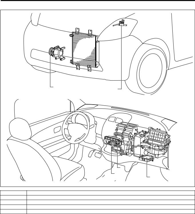
1-2 LOCATION OF COMPONENTS
b |
a |
|
d
c
e
T11H1519S33
aPressure switch
bCompressor magnet clutch
cBlower switch
dA/C switch
eEngine control computer
 Loading...