How it Works
Log In / Sign Up
Buy Points
How it Works
FAQ
Contact Us
Questions and Suggestions
Users
Daihatsu
Loading...
F
F300 1989
F300 1990
F300 1991
F300 1992
F300 1993
F300 1994
F300 1995
F300 1996
F300 1997
F300 1998
F300 Workshop
Feroza F300 HD Engine
FEROZA ROCKY F70 F75 F77 F80 F85
7
Feroza Sportrak
G
G200
Gran Move G303 G301
H
Hijet
2
Hijet 1989
Hijet 1989 1994
Hijet 1990
Hijet 1991
Hijet 1992
Hijet 1993
Hijet 1994
M
Materia
MATERIA 2006
Materia 2006 – (2013)
MATERIA 2007
MATERIA 2008
MATERIA 2009
MATERIA 2010
MATERIA 2011
MATERIA 2012
MATERIA 2013
Mira 1999
Mira 2000
Mira 2002
Mira 2003
Motor
2
Move L601 Werkstatthandbuch
R
ROCKY
Rocky-Fourtrak
S
S85 HIJET
Servicio
SIRION
11
Sirion 1998
Sirion 1998 2004
Sirion 2004
Sirion 2005
Sirion 2006
Sirion 2007
Sirion 2008
Sirion 2009
Sirion 2010
SIRION M300
40
T
Terios
6
Terios 1997
Terios (2000)
Terios (2001)
Terios (2002)
Terios 2003
Terios (2003).Terios (2004).Terios (2005)
Terios 2007
Terios 2009
Terios II 2006
Terios II 2007
Terios II 2008
Terios II 2009
Terios II 2010
Terios J100
Terios J102 Wiring Diagram
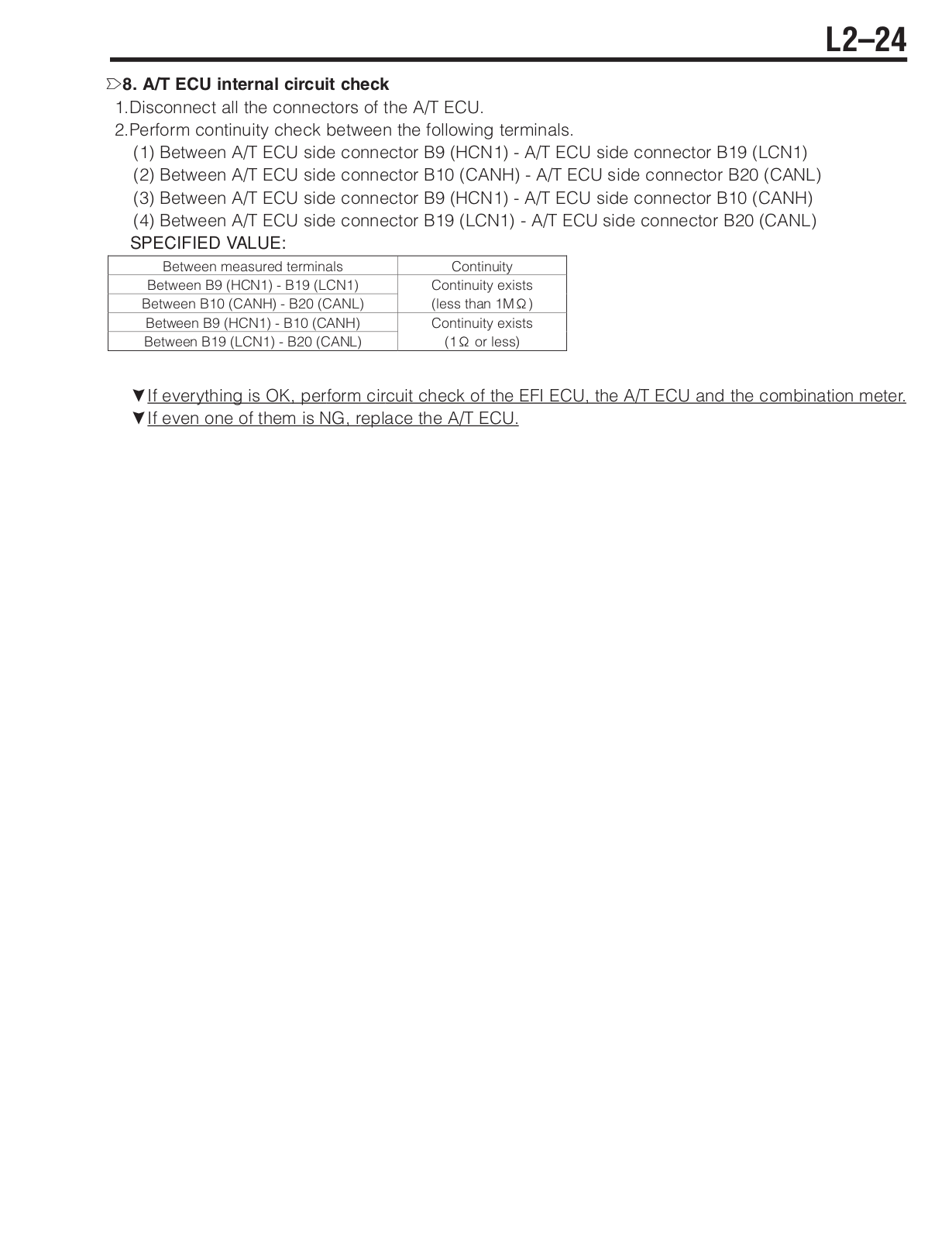
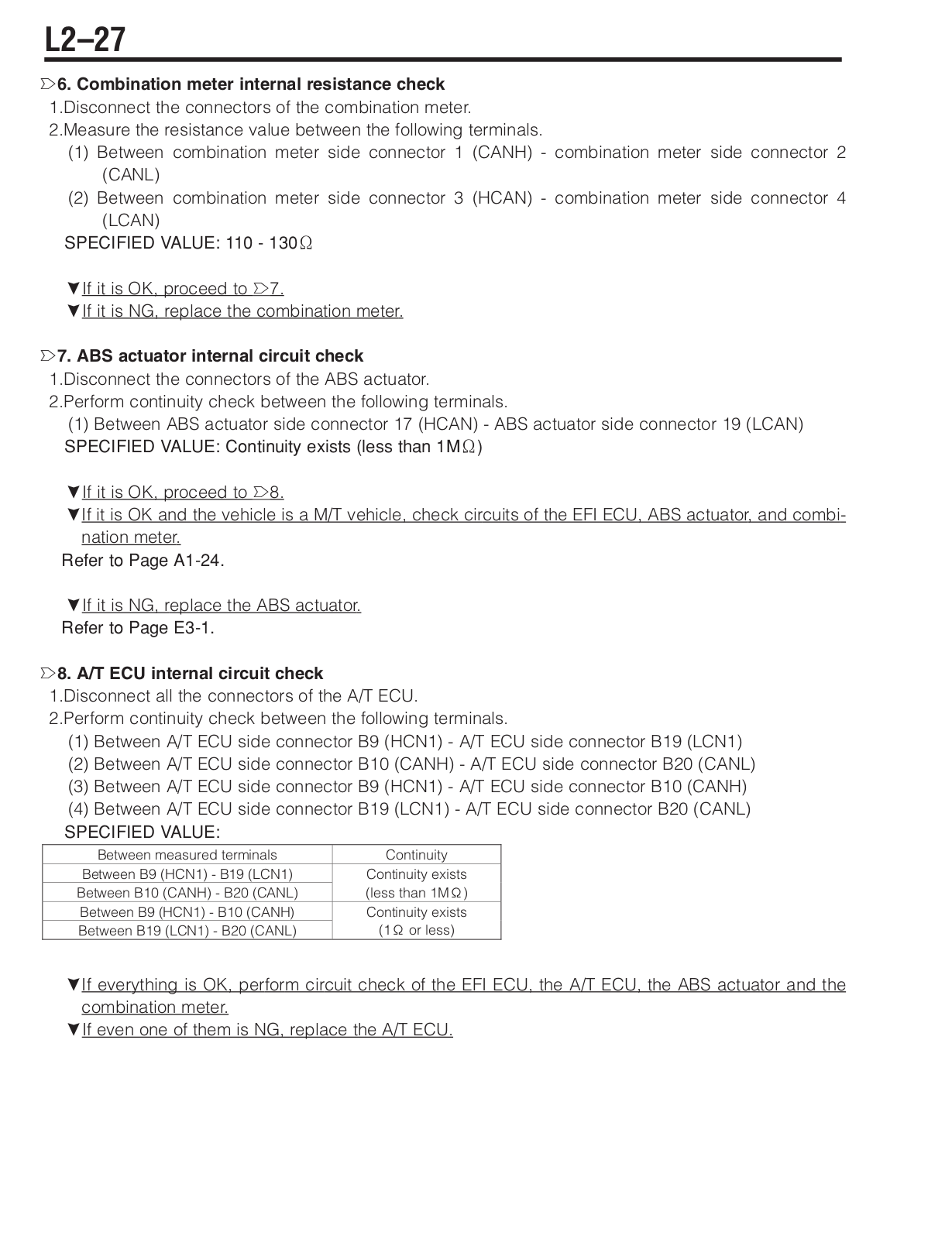
Type A4Q, A4R Automatic Transmission (Electrically-Controlled)
TYPE K3 ENGINE
9
Y
YRV Faultcodes
Loading...
Loading...
Nothing found
Sirion 2007
User Manual
1628 pgs
51.49 Mb
6
Table of contents
Loading...
Daihatsu Sirion 2007 User Manual
...
Daihatsu User Manual
Download
Specifications and Main Features
Frequently Asked Questions
User Manual
Download
Loading...
+
hidden pages
Unhide
You need points to download manuals.
1 point = 1 manual.
You can buy points or you can get point for every manual you upload.
Buy points
Upload your manuals
 Loading...