


 Loading...
6 |
STRUCTURE |
ΛΦ45/55 series
TECHNICAL DATA
DIAGNOSTICS
BRAKE DIAGRAMS FOR THE FULLY PNEUMATIC BRAKE SYSTEM
OPERATION OF BRAKE COMPONENTS
BRAKE SYSTEM AND COMPONENTS
BRAKING PERFORMANCE AND BRAKE EQUALISATION
0
1
2
3
4
5
© 200436 |
DW23259602 |
https://www.truck-manuals.net/
https://www.truck-manuals.net/

6 |
|
TECHNICAL DATA |
|
|||
ΛΦ45/55 series |
|
Contents |
|
|
||
CONTENTS |
|
|
|
|
||
Page |
Date |
0 |
||||
|
|
|||||
. . . . . . . . . . . . . . . . . . . . . . . . .1. BRAKE SYSTEM AND COMPONENTS |
. . . . . . . . .1-1 |
. . 200436 |
|
|||
1.1 |
General . . . . . . . . . . . . . . . . . . . . . . . . . . . . . . . . . . . . . . . . . . . . . |
. . . . . . 1-1 . . . . |
. 200436 |
|
||
1.2 |
Tightening torques. . . . . . . . . . . . . . . . . . . . . . . . . . . . . . . . . . . . . |
. . . . . . 1-12 . . . |
. 200436 |
|
||
1.3 |
Lubricants . . . . . . . . . . . . . . . . . . . . . . . . . . . . . . . . . . . . . . . . . . |
. . . . . . 1-16 . . . |
. 200436 |
|
||
© 200436 |
1 |
https://www.truck-manuals.net/

TECHNICAL DATA |
6 |
|
Contents |
ΛΦ45/55 series |
|
0
2 |
© 200436 |
https://www.truck-manuals.net/

6 |
TECHNICAL DATA |
||
ΛΦ45/55 series |
Brake system and components |
|
|
1. BRAKE SYSTEM AND COMPONENTS |
|
|
|
|
|
0 |
|
1.1 GENERAL |
|
||
Coding of components
All components have been provided with number codes.
Structure of the code
First digit
Often used:
1Energy supply (pressure)
2Energy discharge (outgoing command)
3Bleed
4 Control connection (incoming command) Little used:
0Suction connection
5Free
6Free
7Anti-freeze connection
8 Lubricating oil connection
9Coolant connection
Where one connection performs several functions, additional 1stdigits will be allocated. These are separated by a hyphen.
Second digit
If there are several connections with the same function, a 2nd digit will be added immediately after the 1st one.
Application example: empty/load relay valve
Meaning:
1Air compressor energy supply
2Energy discharge (command) to the next component
41Control connection (incoming)
42Second control connection (incoming)
COMPRESSOR |
|
Knorr model |
|
Type: |
LK3839 |
Version: |
1-cylinder, liquid-cooled |
© 200436 |
1-1 |
https://www.truck-manuals.net/
TECHNICAL DATA |
6 |
Brake system and components
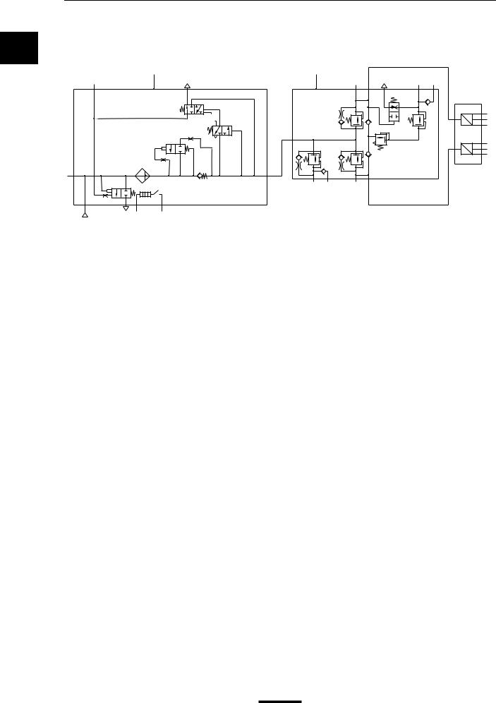
AIR SUPPLY UNIT
0 Front axle, leaf-sprung
A B
23
|
|
|
D |
|
|
F |
1 |
|
|
N |
|
|
|
|
|
1 |
C |
|
21 |
|
|
||
|
|
|
|
E |
0 |
|
24 26 |
|
|
|
|
|
G |
12 |
3 |
<![if ! IE]> <![endif]>6.1 |
<![if ! IE]> <![endif]>6.2 |
|
|
ΛΦ45/55 series
21 |
3 |
23 25 |
|
|
|
H |
|
M |
|
|
|
|
|
|
P U |
6.2 |
|
|
|
|
6.3 |
||
|
|
L |
P |
6.4 |
|
|
|
|
|||
|
|
|
6.5 |
||
J |
K |
|
|
U |
|
|
P |
6.6 |
|||
|
|
|
|
6.7 |
|
|
|
|
|
|
|
22
R600702
A Air dryer/pressure regulator (unit)
B 4-circuit protection valve (unit)
C Filter/drying grid
D Pressure regulator
EBlow-off valve
F Pneumatic time switch for regeneration
GHeating element
H Pressure relief valve with bypass, circuit 1
J Pressure relief valve with bypass, circuit 2
K Pressure limiting valve, circuit 3
L Pressure relief valve, circuit 3
MFlowback valve, circuit 3
N Pressure relief valve with bypass, circuit 4
PPressure sensors
Cut-out pressure of pressure regulator |
10.0 ≥ 0.2 bar |
Cut-in pressure of pressure regulator |
1.2 ≥ 0.2 bar under cut-out pressure |
Supply pressure in circuit 1, connection 21 |
max. 10 bar |
Supply pressure in circuit 2, connection 22 |
max. 10 bar |
Supply pressure in circuit 3, connection 23 |
8.5 - 0.4 bar |
Supply pressure in circuit 3, connection 25 |
8.5 - 0.6 bar |
Supply pressure in circuit 4, connection 24 |
max. 10 bar |
Supply pressure in circuit 4, connection 26 |
max. 10 bar |
Opening pressure of circuits 1, 2 and 4 |
8.5 bar |
Opening pressure of circuit 3 |
7.0 bar |
Closing pressure of circuits 1, 2 and 4 |
7 bar |
Closing pressure of circuit 3 |
5.5 bar |
Cut-in temperature of heating element |
7 C |
Cut-out temperature of heating element |
29 C |
Circuit 1 activation pressure for flowback function |
|
of circuit 3 |
< 4.5 bar |
1-2 
 © 200436
https://www.truck-manuals.net/
6 |
TECHNICAL DATA |
ΛΦ45/55 series
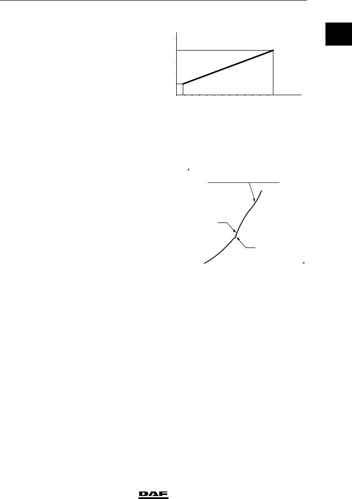
Pressure sensor reading, circuits 1 and 2 (connections 6.2 - 6.7 in the diagram above)
Ua(V)
5V
4V
Brake system and components
0
3V
2V
1V
0V
0 |
2 |
4 |
6 |
8 |
10 |
12 P21.22(bar) |
R600701
FOOT BRAKE VALVE
|
P21 |
|
|
|
|
|
|
|
|
|
|
|
|
|
|
|
|
|
|
|
|
|
|
|
|
|
|
|
|
|
||||
|
P22 bar |
|
|
|
|
|
|
|
|
|
|
|
|
|
|
|
|
|
|
|
|
|
|
|
|
|
|
|
|
|
||||
|
10 |
|
|
|
|
|
|
|
P21-P22 = 0,3 – 0,15 bar |
|||||||||||||||||||||||||
|
|
|
|
|
|
|
|
|||||||||||||||||||||||||||
|
9 |
|
|
|
|
|
|
|
|
|
|
|
|
|
|
|
|
|
|
|
|
|
|
|
|
|
|
|
|
|
|
|
|
|
|
|
|
|
|
|
|
|
|
|
|
|
|
|
|
|
|
|
|
|
|
|
|
|
|
|
|
|
|
|
|
|
|
|
|
|
8 |
|
|
|
|
|
|
|
|
|
|
|
|
|
|
|
|
|
|
|
|
|
|
|
|
|
|
|
|
|
|
|
|
|
|
|
|
|
|
|
|
|
|
|
|
|
|
|
|
|
|
|
|
|
|
|
|
|
|
|
|
|
|
|
|
|
|
|
|
|
7 |
|
|
|
|
|
|
|
|
|
|
|
|
|
|
|
|
|
|
|
|
|
|
|
|
|
|
|
|
|
|
|
|
|
|
|
|
|
|
|
|
|
|
|
|
|
|
|
|
|
|
|
|
|
|
|
|
|
|
|
|
|
|
|
|
|
|
|
|
|
6 |
|
|
|
|
|
|
|
|
|
|
21 |
|
|
|
|
|
|
|
|
|
|
|
|
|
|
|
|
|
|
|
|
||
|
|
|
|
|
|
|
|
|
|
|
|
|
|
|
|
|
|
|
|
|
|
|
|
|
|
|
|
|
|
|
||||
|
5 |
|
|
|
|
|
|
|
|
|
|
|
|
|
|
|
|
|
|
|
|
|
|
|
|
|
|
|
|
|
|
|||
|
|
|
|
|
|
|
|
|
|
|
|
|
|
|
|
|
|
|
|
|
|
|
|
|
|
|
|
|
|
|
||||
|
4 |
|
|
|
|
|
|
|
|
|
|
|
|
|
|
|
|
|
|
|
|
|
|
|
|
|
|
|
|
|
|
|
|
|
|
|
|
|
|
|
|
|
|
|
|
|
|
|
|
|
|
|
|
|
|
|
|
|
|
|
|
|
|
|
|
|
|
|
|
|
3 |
|
|
|
|
|
|
|
|
|
|
|
|
|
|
|
|
|
|
22 |
|
|
|
|
|
|
|
|
|
|
|
|
||
|
|
|
|
|
|
|
|
|
|
|
|
|
|
|
|
|
|
|
|
|
|
|
|
|
|
|
|
|
|
|
||||
|
2 |
|
|
|
|
|
|
|
|
|
|
|
|
|
|
|
|
|
|
|
|
|
|
|
|
|
|
|
|
|
|
|||
|
|
|
|
|
|
|
|
|
|
|
|
|
|
|
|
|
|
|
|
|
|
|
|
|
|
|
|
|
|
|
||||
|
1 |
|
|
|
|
|
|
|
|
|
|
|
|
|
|
|
|
|
|
|
|
|
|
|
|
|
|
|
|
|
|
|
|
|
|
|
|
|
|
|
|
|
|
|
|
|
|
|
|
|
|
|
|
|
|
|
|
|
|
|
|
|
|
|
|
|
|
|
|
|
0 |
|
|
|
|
|
|
|
|
|
|
|
|
|
|
|
|
|
|
|
|
|
|
|
|
|
|
|
|
|
|
|
|
|
|
|
|
|
|
2 |
3 |
4 |
5 |
6 |
7 |
8 |
9 10 11 12 |
|
|||||||||||||||||||||
|
1 |
|
||||||||||||||||||||||||||||||||
|
|
|
|
|
|
|
|
|
|
|
|
|
|
|
|
|
|
|
|
|
|
|
|
|
|
|
|
|
C (cm) |
|||||
Pressure difference between circuits 1 and 2 (be- |
|
|
|
|
|
|
|
|
|
|
|
|
|
|
|
|
|
|
|
|
|
|
|
|
|
|
|
|
|
R600594 |
||||
0.3 ≥ 0.15 bar |
|
|
|
|
|
|
|
|
|
|
|
|
|
|
|
|
|
|
|
|
|
|
|
|
|
|
|
|
|
|||||
tween 0 and 3 bar) |
|
|
|
|
|
|
|
|
|
|
|
|
|
|
|
|
|
|
|
|
|
|
|
|
|
|
|
|
|
|||||
Pressure reduction in circuits 1 and 2 from 10 to |
|
|
|
|
|
|
|
|
|
|
|
|
|
|
|
|
|
|
|
|
|
|
|
|
|
|
|
|
|
|
|
|
|
|
8 bar |
|
|
|
|
|
|
|
|
|
|
|
|
|
|
|
|
|
|
|
|
|
|
|
|
|
|
|
|
|
|
|
|
|
|
Connection 11 |
circuit 1 supply |
|
|
|
|
|
|
|
|
|
|
|
|
|
|
|
|
|
|
|
|
|
|
|
|
|
|
|||||||
Connection 12 |
circuit 2 supply |
|
|
|
|
|
|
|
|
|
|
|
|
|
|
|
|
|
|
|
|
|
|
|
|
|
|
|||||||
Connection 21 |
circuit 1 braking pressure |
|
|
|
|
|
|
|
|
|
|
|
|
|
|
|
|
|
||||||||||||||||
Connection 22 |
circuit 2 braking pressure |
|
|
|
|
|
|
|
|
|
|
|
|
|
|
|
|
|
||||||||||||||||
© 200436 |
1-3 |
https://www.truck-manuals.net/
TECHNICAL DATA |
6 |
|
Brake system and components |
ΛΦ45/55 series |
|
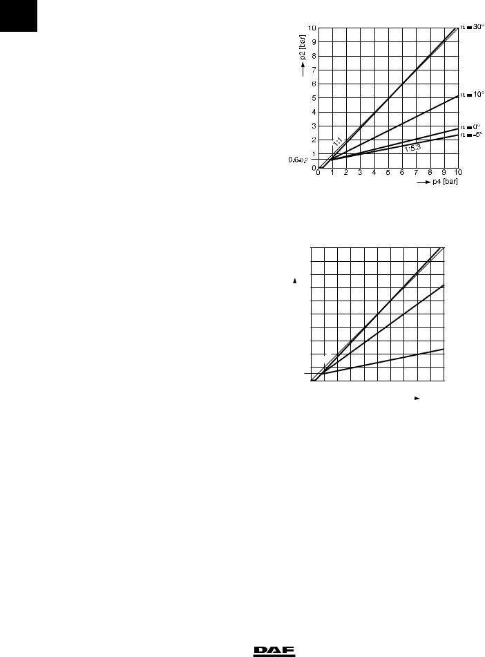
LOAD-DEPENDENT CONTROL VALVE,
0LEAF SPRING
Characteristic
LOAD-DEPENDENT CONTROL VALVE,
AIR SUSPENSION
Characteristic
| <![if ! IE]> <![endif]>[bar] |
10 |
|
9 |
||
| <![if ! IE]> <![endif]>p2 |
8 |
|
|
|
|
|
|
7 |
|
|
|
6
5
4
3
2
1
0.6–0.2
1:1
R600704
p41p42= 4.65 bar
p41p42= 3 bar
p41p42= 0.3 bar
|
0 |
1 |
2 |
3 |
4 |
5 |
6 |
7 |
8 |
9 |
10 |
|
|
|
|
|
|
|
|
|
|
|
|
p4 [bar] |
|
|
|
|
|
|
|
|
|
|
|
|
||
|
|
|
|
|
|
|
|
|
|
|
|
R600705 |
LOW-PRESSURE SWITCH |
|
|
|
|
|
|
|
|
|
|
|
|
Cut-out pressure: |
5.2 ≥ 0.2 bar |
|
|
|
|
|
|
|
|
|
||
1-4 |
© 200436 |
https://www.truck-manuals.net/
6 |
<![if ! IE]> <![endif]>P2(bar) |
10 |
|
|
|
|
|
|
|
|
|
|
|
|
|
|
|
|
|
|
|
|
|
||
|
|
|
|
|
|
|
|
|
|
|
|
|
|
|
|
|
|
|
|
|
|||||
9 |
|
|
|
|
|
|
|
|
|
|
|
|
|
|
|
|
|
|
|
|
|
||||
|
|
|
|
|
|
|
|
|
|
|
|
|
|
|
|
|
|
|
|
|
|
||||
|
8 |
|
|
|
|
|
|
|
|
|
|
|
|
|
|
|
|
|
|
|
|
|
|||
|
|
|
|
|
|
|
|
|
|
|
|
|
|
|
|
|
|
|
|
|
|
||||
|
7 |
|
|
|
|
|
|
|
|
|
|
|
|
|
|
|
|
|
|
|
|
|
|||
|
|
|
|
|
|
|
|
|
|
|
|
|
|
|
|
|
|
|
|
|
|
||||
|
6 |
|
|
|
|
|
|
|
|
|
|
|
|
|
|
|
|
|
|
|
|
|
|||
|
|
|
|
|
|
|
|
|
|
|
|
|
|
|
|
|
|
|
|
|
|
||||
|
5 |
|
|
|
|
|
|
|
|
|
|
|
|
|
|
|
|
|
|
|
|
|
|||
|
|
|
|
|
|
|
|
|
|
|
|
|
|
|
|
|
|
|
|
|
|
||||
|
|
|
|
|
|
|
|
|
|
|
|
|
|
|
|
|
|
|
|
|
|
||||
|
4 |
|
|
|
|
|
|
|
|
|
|
|
|
|
|
|
|
|
|
|
|
|
|||
|
|
|
|
|
|
|
|
|
|
|
|
|
|
|
|
|
|
|
|
|
|
||||
|
3 |
|
|
|
|
|
|
|
|
|
|
|
|
|
|
|
|
|
|
|
|
|
|||
|
|
|
|
|
|
|
|
|
|
|
|
|
|
|
|
|
|
|
|
|
|
||||
|
2 |
|
|
|
|
|
|
|
|
|
|
|
|
|
|
|
|
|
|
|
|
|
|||
|
1 |
|
|
|
|
|
|
|
|
|
TECHNICAL |
|
|
|
DATA |
|
|||||||||
ΛΦ45/55 series |
|
|
|
|
|
|
|
|
|
Brake |
system and |
components |
|
||||||||||||
RELAY VALVE |
|
|
|
|
|
|
|
|
|
|
|
|
|
|
|
|
|
|
|
|
|
|
|
|
|
Fitted with internal filter and silencer |
|
|
<![if ! IE]> <![endif]>(bar) |
9 |
|
|
|
|
|
|
|
|
|
|
|
|
|
|
|
|
|
|
|
||
|
|
|
<![if ! IE]> <![endif]>P 2 |
8 |
|
|
|
|
|
|
|
|
|
|
|
|
|
|
|
|
|
|
|
||
|
|
|
|
|
|
7 |
|
|
|
|
|
|
|
|
|
|
|
|
|
|
|
|
|
|
|
|
|
|
|
|
|
6 |
|
|
|
|
|
|
|
|
|
|
|
|
|
|
|
|
|
|
|
|
|
|
|
|
|
5 |
|
|
|
|
|
|
|
|
|
|
|
|
|
|
|
|
|
|
|
|
|
|
|
|
|
4 |
|
|
|
|
|
|
|
|
|
|
|
|
|
|
|
|
|
|
|
|
|
|
|
|
|
3 |
|
|
|
|
|
|
|
|
|
|
|
|
|
|
|
|
|
|
|
|
|
|
|
|
|
2 |
|
|
|
|
|
|
|
|
|
|
|
|
|
|
|
|
|
|
|
|
|
|
|
|
|
1 |
|
|
|
|
|
|
|
|
|
|
|
|
|
|
|
|
|
|
|
|
|
|
|
|
|
0 |
|
|
1 |
|
2 |
|
3 |
|
4 |
|
5 |
6 |
|
7 |
8 |
9 |
|
|
|
|
|
|
|
|
|
|
|
|
|
|
|
|
|
|
|
|
|
|
|
|
P4 (bar) |
|
|
||
|
|
|
|
|
|
|
|
|
|
|
|
|
|
|
|
|
|
|
|
|
|
R 600363 |
|
|
|
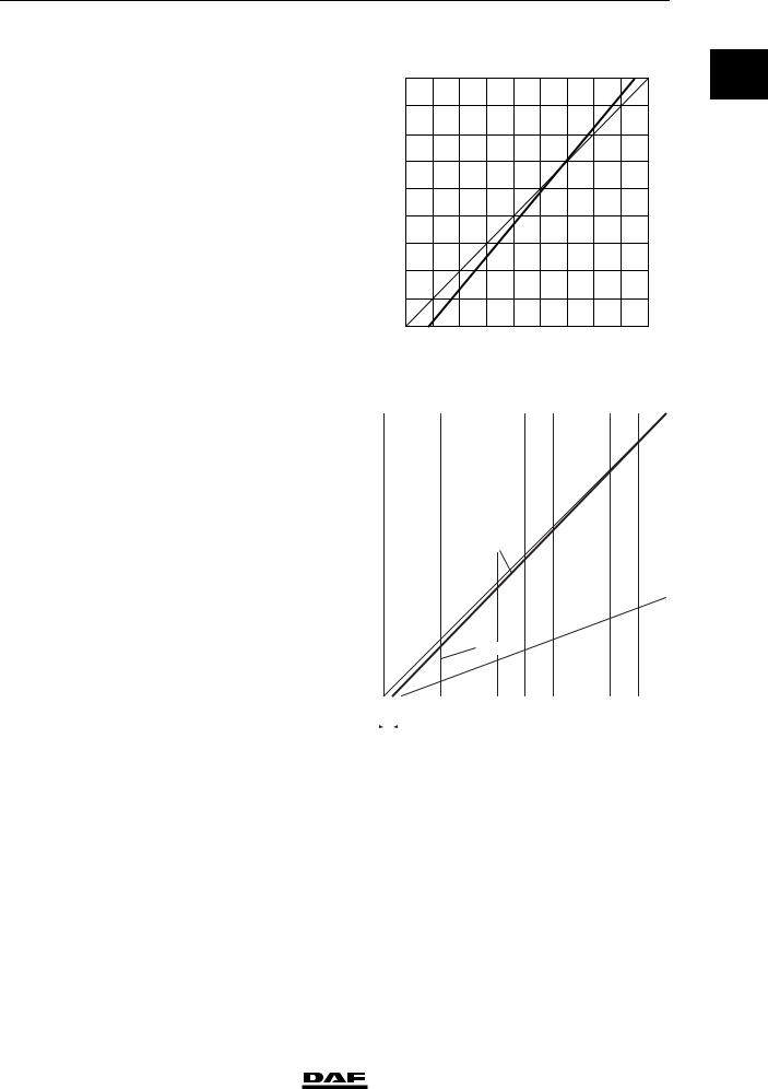
EMPTY/LOAD RELAY VALVE |
|
|
|
|
|
|
|
|
|
|
|
|
|
|
|
|
|
|
|
|
|
|
|
|
|
|
|
|
|
|
|
|
|
|
|
|
|
|
P42 = P41 |
|
|
|
|
|
|
|
|
|
|||
|
|
|
|
|
|
|
|
|
|
|
|
|
|
|
|
|
|
.7 |
|
|
|
|
|
|
|
|
|
|
|
|
|
|
|
|
|
|
|
|
|
|
|
|
1:2 |
|
|
|
|
|
|
|
|
|
|
|
|
|
|
|
|
|
|
|
|
|
P42 = 0 |
|
|
|
|
|
|
|
|
|
|||
|
|
|
|
|
|
|
|
|
|
|
|
|
|
|
|
|
|
|
|
|
|
||||
|
|
|
|
|
|
|
|
|
|
|
|
|
|
|
|
|
|
|
|
|
|
|
|
|
|
|
|
|
|
|
|
|
|
|
|
|
|
|
|
|
|
|
|
|
|
|
|
|
|
|
|
|
|
|
|
|
|
|
|
|
|
|
|
|
|
|
|
|
|
|
|
|
|
|
|
|
|
|
|
0 |
|
|
1 |
2 |
3 |
4 |
5 |
6 |
7 |
|
8 |
9 |
10 |
||||||||||
|
|
|
|
|
|
0,25+ 0,1 |
|
|
|
|
|
|
|
|
|
|
|
|
P41(bar) |
|
|
||||
|
|
|
|
|
|
|
|
|
|
|
|
|
|
|
|
|
|
|
|
|
|
|
|
||
Maximum reduction ratio |
1 : 2.7 |
|
|
|
|
|
|
|
|
|
|
|
|
|
|
|
|
R600330 |
|||||||
|
|
|
|
|
|
|
|
|
|
|
|
|
|
|
|
|
|
|
|||||||
Actuating pressure |
0.25 bar |
|
|
|
|
|
|
|
|
|
|
|
|
|
|
|
|
|
|
|
|||||
Fitted with internal filter and silencer |
|
|
|
|
|
|
|
|
|
|
|
|
|
|
|
|
|
|
|
|
|
|
|
|
|
0
© 200436 |
1-5 |
https://www.truck-manuals.net/
|
|
TECHNICAL DATA |
6 |
|
|
|
Brake system and components |
ΛΦ45/55 series |
|
|
|
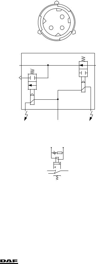
ABS VALVE |
|
|
0 |
|
15 ≥ 5 ohm at 25 C |
||
|
Resistance of magnet coil |
|||
|
|
|||
|
|
|
|
|
Electrical connections
1.Bleed magnet coil
2.Earth
3. |
Aerate magnet coil |
1 |
2 3
2 |
1 |
3
1 2 3
R600370
ASR solenoid valve
1. Supply
2. Port, two-way valve
3. Bleed
1 |
2 |
3
R600484
TRAILER VEHICLE CONTROL VALVE |
|
Knorr model |
|
Type: |
AC 597BA |
Advance |
|
Input pressure |
3 bar |
Output pressure |
3.2 bar |
(equals 0.2 bar advance = factory setting) |
|
1-6 |
© 200436 |
https://www.truck-manuals.net/
6 |
TECHNICAL DATA |
||
ΛΦ45/55 series |
Brake system and components |
|
|
Advance adjustment |
|
|
|
|
|
0 |
|
Adjusting screw (Allen type, 6 mm) |
|
|
|
Clockwise increases the advance |
|
||
Anti-clockwise decreases the advance |
|
|
|
|
|
|
|
Knorr model |
|
|
|
Type: |
AC 597C |
||
Advance |
|
|
|
Input pressure |
3 bar |
||
Output pressure |
3.5 bar |
||
(equals 0.5 bar advance = factory setting) |
|
|
|
Advance adjustment |
|
|
|
Adjusting screw (Allen type, 6 mm) |
|
|
|
Clockwise increases the advance |
|
|
|
Anti-clockwise decreases the advance |
|
|
|
PARKING BRAKE VALVE WITH TRAILER |
|
|
|
VEHICLE CONNECTION |
|
|
|
Wabco model
Type:
Max. output pressure in driving position
961 723 134 0 |
approx. 8 bar |
© 200436 |
1-7 |
https://www.truck-manuals.net/
|
|
TECHNICAL DATA |
6 |
|
|
|
Brake system and components |
ΛΦ45/55 series |
|
|
|
PARKING BRAKE VALVE WITHOUT TRAILER |
|
|
0 |
|
|
|
|
|
VEHICLE CONNECTION |
|
|
|
|
Wabco model |
|
|
|
|
|
Type: |
961 723 036 0 |
|
|
|
Max. output pressure in driving position |
approx. 8 bar |
|
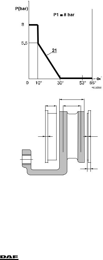
BRAKE PADS
A
C B
D |
E |
F
R600489
Knorr model
Maximum brake block thickness (C) Maximum lining thickness (E) Minimum brake block thickness (F)
Replacing:
30 mm
2 mm (at the thinnest point)
11 mm (at the thinnest point) with 9mm rear plate thickness (D)
all brake pads at the same time for each axle, and with the specified lining only.
1-8 |
© 200436 |
https://www.truck-manuals.net/
6 |
TECHNICAL DATA |
|
|
ΛΦ45/55 series |
Brake system and components |
|
|
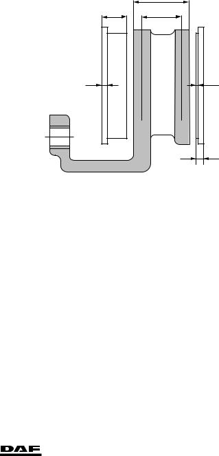
Wabco PAN 17 version: |
|
|
|
|
|
0 |
|
Maximum brake block thickness (C) |
26 mm |
||
Maximum lining thickness (E) |
2 mm (at the thinnest point) |
||
Minimum brake block thickness (F) |
9 mm (at the thinnest point) with 7mm rear plate |
|
|
|
thickness (D) |
|
|
Replacing:
Wabco PAN 19-1+ and PAN 19-2 versions:
Maximum brake block thickness (C) Maximum lining thickness (E) Minimum brake block thickness (F)
all brake pads at the same time for each axle, and with the specified lining only.
30 mm
2 mm (at the thinnest point)
11 mm (at the thinnest point) with 9mm rear plate thickness (D)
Replacing: |
all brake pads at the same time for each axle, and |
|
with the specified lining only. |
BRAKE DISC
A
C B
D |
E |
F
R600489
Knorr model
Maximum brake disc thickness (A) Minimum brake disc thickness (B)
45 mm
37 mm (rejection dimension, disc must be replaced)
Minimum thickness, turning dimension |
40 mm |
Note:
If it is established during brake pad replacement that the brake thickness is less than or equal to 39 mm, the brake disc must also be replaced.
© 200436 |
1-9 |
https://www.truck-manuals.net/
|
TECHNICAL DATA |
|
|
Brake system and components |
|
|
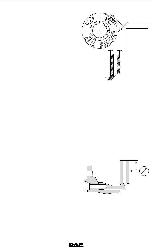
The following signs of wear are permissible: |
|
0 |
||
A1 Crazy cracking. |
B1 Cracks running to the centre up to 1.5 mm wide and deep, max. 0.75 x friction surface width (a).
C1 Unevenness in the disc surface up to
1.5 mm. Not permissible:
D1 Through-going cracks.
Wabco model
PAN 17 version:
Maximum brake disc thickness (A)
Minimum brake disc thickness (B)
Minimum thickness, turning dimension
The following signs of wear are permissible:
A1 Crazy cracking.
B1 Cracks running to the centre up to 1.5 mm wide and deep,
max. 0.75 x friction surface width (a).
C1 Unevenness in the disc surface up to
1.5 mm. Not permissible:
D1 Through-going cracks.
Brake disc wobble 0.15 mm
AMeasuring distance is 35 mm
6
ΛΦ45/55 series
A1 |
B1 |
|
<![if ! IE]> <![endif]>a |
max. 0,75 x a
max. 1,5 mm
D1 |
C1 |
R600471
34 mm
28 mm (rejection dimension, disc must be replaced)
30 mm
<![if ! IE]><![endif]>A
R600508
1-10 |
© 200436 |
https://www.truck-manuals.net/
6 |
|
TECHNICAL DATA |
|
|
ΛΦ45/55 series |
Brake system and components |
|
|
|
PAN 19-1+ and PAN 19-2 versions: |
|
|
|
|
|
|
0 |
||
Maximum brake disc thickness (A) |
45 mm |
|||
Minimum brake disc thickness (B) |
38 mm (rejection dimension, disc must be |
|||
|
|
replaced) |
|
|
Minimum thickness, turning dimension |
40 mm |
|
||
The following signs of wear are permissible: |
|
|
|
|
A1 |
Crazy cracking. |
|
|
|
B1 |
Cracks running to the centre up to 1.5 mm |
|
|
|
|
wide and deep, |
|
|
|
|
max. 0.75 x friction surface width (a). |
|
|
|
C1 |
Unevenness in the disc surface up to |
|
|
|
|
1.5 mm. |
|
|
|
Not permissible: |
|
|
|
|
D1 |
Through-going cracks. |
|
|
|
Brake disc wobble 0.15 mm |
|
|
|
|
A |
Measuring distance is 35 mm |
|
|
|
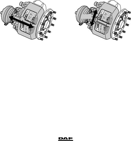
BRAKE CALLIPER |
|
|
|
|
Knorr model |
|
|
|
|
A |
Y - X |
|
R600708 |
R600712 |
Brake calliper play in axial direction (direction A) |
0.6 - 1.0 mm |
Brake calliper play on guide bushes ("Y" - "X") |
max. 2.0 mm |
Play between brake calliper carrier and brake |
|
pads ("Y" - "X" direction) |
0.3 - 0.9 mm |
Wabco model |
|
Play between brake pad/brake disc: |
|
Manually adjustable brake pad/brake disc play |
|
after fitting brake pads: |
0.7 mm |
© 200436 |
1-11 |
https://www.truck-manuals.net/
|
|
TECHNICAL DATA |
6 |
|
|
|
Brake system and components |
ΛΦ45/55 series |
|
|
|
1.2 TIGHTENING TORQUES |
|
|
0 |
|
|
|
|
|
The tightening torques stated in this section are |
|
|
|
|
|
|
|
|
|
|
different from the standard tightening torques |
|
|
|
|
stated in the overview of the standard tightening |
|
|
|
|
torques. The other threaded connections not |
|
|
|
|
specified must therefore be tightened to the |
|
|
|
|
torque stated in the overview of standard |
|
|
|
|
tightening torques. |
|
|
|
|
When attachment bolts and nuts are replaced, it |
|
|
|
|
is important that - unless stated otherwise - these |
|
|
|
|
bolts and nuts are of exactly the same length and |
|
|
|
|
property class as those removed. |
|
|
|
|
QUICK-RELEASE COUPLING |
|
|
|
|
Parker |
20 - 30 Nm |
|
|
|
SPRING BRAKE CYLINDER |
|
|
|
|
Attachment nuts |
195 Nm |
|
|
|
Release bolt |
70 Nm |
|
|
|
Clamping strip attachment nut |
40 Nm |
|
|
|
BRAKE CYLINDER |
|
|
|
|
Attachment nuts |
195 Nm |
|
|
|
BRAKE CALLIPER - BRAKE CARRIER, Knorr |
|
|
|
|
model |
285 Nm (1) |
|
|
|
Sliding sleeve Allen screws (SB7000) |
||
|
|
Sliding sleeve Allen screws (SN7000) |
180 Nm + 90 (1) |
|
|
|
Pressure tool, guide bush bellows |
8 Nm |
|
|
|
Rubber bearing bush pressure tool (only |
|
|
|
|
SN7000) |
8 - 45 Nm |
|
(1) Always use new bolts, provided with locking compound. New bolts are supplied with locking compound already applied.
R600744
1-12 |
© 200436 |
https://www.truck-manuals.net/
6 |
|
TECHNICAL DATA |
||
ΛΦ45/55 series |
|
Brake system and components |
|
|
|
|
|
|
|
Brake calliper attach- |
440 Nm (1) (2) |
|
|
0 |
ment bolts, front axle |
|
|||
|
|
|
||
|
|
|
|
|
(1)From production date 2003-37 there is one fitted bolt and flange bolts are also fitted.
The fitted bolt must be fitted at the position marked by a small hole.
(2)In the case of versions with Knorr disc brakes, the
attachment of the brake calliper against the stub axle changed starting from production week 2002-25. Five
bolts are now used instead of six bolts. There is still a hole for the 6th bolt on the brake carrier, but there is no hole on the stub axle.
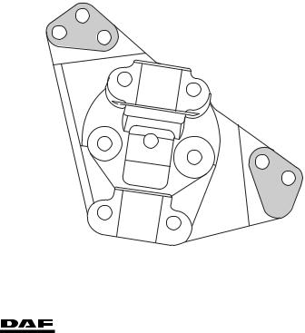
Brake calliper attach- |
440 Nm (1) |
ment bolts, rear axle |
(1)From production date 2003-37 there is one fitted bolt and flange bolts are also fitted.
-In the case of the 11.26 rear axle, the fitted bolt must be fitted at the position marked "X".
-In the case of the 11.32 rear axle, the fitted bolt must be fitted at the position marked by a small hole.
X
R600791
BRAKE CALLIPER - BRAKE CARRIER,
Wabco model
Locking bracket bolt (PAN 17) |
20 Nm |
Locking bracket bolt (PAN 19-1+ and PAN 19-2) |
37 Nm |
Guide bush Allen screws (PAN 17) |
340 Nm |
Guide bush Allen screws (PAN 19-1+ and |
|
PAN 19-2) |
300 Nm |
Brake calliper attachment bolts against stub axle |
|
or back plate (PAN 17) |
213 Nm |
Brake calliper attachment bolts against stub axle |
|
or back plate (PAN 19-1+ and PAN 19-2) |
470 Nm |
© 200436 |
1-13 |
https://www.truck-manuals.net/
|
TECHNICAL DATA |
6 |
|
Brake system and components |
ΛΦ45/55 series |
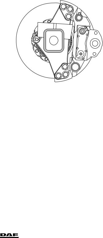
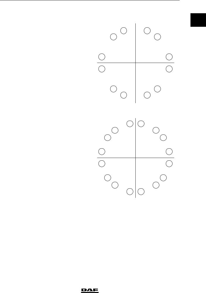
0 |
Tightening sequence of brake calliper |
|
attachment bolts, Wabco model |
|
|
Tightening sequence of brake calliper attachment |
|
bolts:
|
6 |
3 |
2 |
1 |
4 |
5 |
|
|
|
|
|
|
R600520 |
BRAKE DISC |
|
|
|
|
|
|
Knorr model |
|
|
|
|
|
|
Locking plate attachment bolts |
32 Nm |
|
|
|
|
|
Wabco model |
|
|
|
|
|
|
PAN 17 version |
|
≥ 7 Nm |
|
|
|
|
Brake disc attachment bolts on front axle |
115 |
|
|
|
||
Brake disc attachment bolts on rear axle |
130 |
Nm |
|
|
|
|
PAN 19-1+ and PAN 19-2 versions |
|
≥ 21 Nm |
|
|
|
|
Brake disc attachment bolts on front axle |
210 |
|
|
|
||
Brake disc attachment bolts on rear axle |
193 |
Nm |
|
|
|
|
1-14 |
© 200436 |
https://www.truck-manuals.net/
6 |
|
TECHNICAL DATA |
ΛΦ45/55 series |
Brake system and components |
|
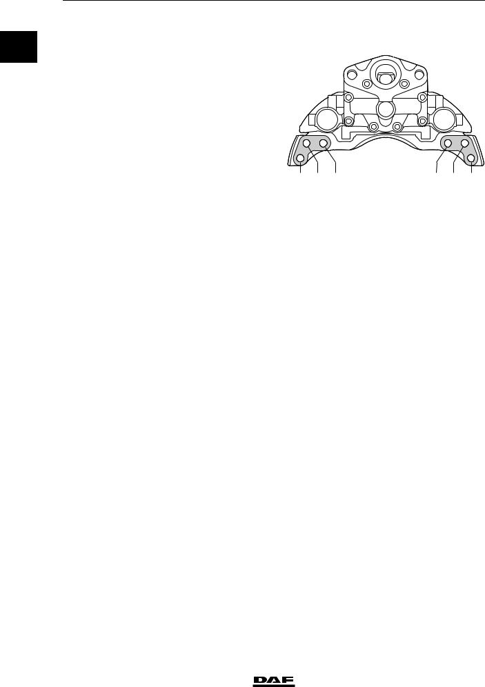
Tightening sequence of brake disc on |
|
0 |
F36 axle |
|
|
|
|
|
|
3 |
7 |
9 |
|
12 |
5 |
2 |
1 |
6 |
11 |
10 |
8 |
4 |
R600732
Tightening sequence of brake disc on F48 axle
3 |
16 |
13 |
7 |
9 |
12 |
5 |
2 |
1 |
6 |
11 |
10 |
8 |
14 |
15 |
4 |
R600731
© 200436 |
1-15 |
https://www.truck-manuals.net/

TECHNICAL DATA |
6 |
|
Brake system and components |
ΛΦ45/55 series |
|
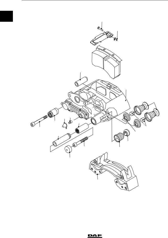
1.3 LUBRICANTS
0
BRAKE CALLIPER, KNORR MODEL SB7000 version

 20
20
18 


 21 19
21 19
 17
17
1
3 |
22 |
4 |
6 |
7 |
|
||
|
|
|
5 |
8 |
16 |
|
|
15
14
11
10
9
13 |
2 |
12
R600541
1-16 |
© 200436 |
https://www.truck-manuals.net/
6 |
TECHNICAL DATA |
||
ΛΦ45/55 series |
Brake system and components |
|
|
Renolit HLT2 (white) for parts 6, 7, 8, the |
|
|
|
|
|
0 |
|
adjusters (not shown), the brake cylinder lever |
|
|
|
and the flange surface for attachment of the |
|
||
brake cylinder |
1448907 |
|
|
Syntheso GL EP1 (green), for parts 3, 5 |
1448908 |
|
|
© 200436 |
1-17 |
https://www.truck-manuals.net/
TECHNICAL DATA |
6 |
Brake system and components
0SN7000 version
6 6a
3
4
8
ΛΦ45/55 series
20
21
18 

 19
19
5
 17
17
1
22
7
 16 23
16 23
15
11 |
14 |
10
|
2 |
|
R600698 |
Renolit HLT2 (white) for parts 3, 6, 7, 8, the |
|
adjusters (not shown), the brake cylinder lever |
|
and the flange surface for attachment of the |
|
brake cylinder |
1448907 |
BRAKE CALLIPER, WABCO MODEL |
|
Renolit G-BRF 2 |
|
1-18 |
© 200436 |
https://www.truck-manuals.net/

6 |
DIAGNOSTICS |
|
|||
ΛΦ45/55 series |
|
Contents |
|
|
|
CONTENTS |
|
|
|
|
|
|
Page |
Date |
|
||
1. DISC BRAKE CONSTRUCTION. . . . . . . . . . . . . . . . . . . . . . . . . . . . . . . . . . . |
. . 1-1 . . . |
. . 200436 |
|
||
1 |
|||||
1.1 Fault-finding table |
1-1 |
200436 |
|||
|
|||||
|
|
|
|
|
|
© 200436 |
1 |
https://www.truck-manuals.net/

DIAGNOSTICS |
6 |
|
Contents |
ΛΦ45/55 series |
|
1
2 |
© 200436 |
https://www.truck-manuals.net/

6 |
DIAGNOSTICS |
|
|
ΛΦ45/55 series |
Disc brake construction |
|
|
1. DISC BRAKE CONSTRUCTION |
|
|
|
1.1 FAULT-FINDING TABLE |
|
|
|
|
|
|
|
|
|
|
1 |
SYMPTOM: SQUEALING/NOISE DURING BRAKING |
|
||
Possible cause |
Remedy |
|
|
|
|
|
|
Worn brake pads |
Check brake pads and brake disc thickness |
|
|
|
|
|
|
Loose parts |
Check disc brake construction |
|
|
|
|
|
|
Wear/damage to hub bearing |
Check hub bearing play |
|
|
|
|
|
|
Wear to internal parts of disc brake construction |
Check internal parts |
|
|
|
|
|
|
Incorrect vehicle combination |
Check vehicle combination |
|
|
|
|
|
|
Incorrect front axle / rear axle brake pressure |
Check front axle / rear axle balance |
|
|
balance |
|
|
|
|
|
||
SYMPTOM: IRREGULAR BRAKE PAD WEAR |
|
|
|
|
|
|
|
Possible cause |
Remedy |
|
|
Fouled/corroded guide bushes |
Check the guide bushes |
|
|
|
|
|
|
Dirt accumulation between moving parts of the disc |
Clean the disc brake construction |
|
|
brake construction |
|
|
|
Moisture and dirt on internal mechanical parts |
Check and clean the brake calliper seals |
|
|
|
|
|
|
Brake pad stuck in the brake calliper Incorrect play |
Check the play between brake pads and brake |
|
|
between brake pads and brake carrier |
carrier |
|
|
|
|
||
SYMPTOM: VEHICLE PULLS TO ONE SIDE DURING BRAKING |
|
|
|
|
|
|
|
Possible cause |
Remedy |
|
|
|
|
|
|
Difference in tyre pressure |
Check / correct tyre pressure |
|
|
|
|
|
|
Difference in tyre size |
Check tyres |
|
|
|
|
|
|
Different brake cylinder diameters |
Check brake cylinder diameters |
|
|
|
|
|
|
Broken springs in brake cylinders |
Check brake cylinders |
|
|
|
|
|
|
Leaking brake cylinders |
Check brake cylinders |
|
|
|
|
|
|
Fouled brake cylinders |
Check the brake cylinders for fouling |
|
|
|
|
|
|
Excessive stub axle bearing play |
Check stub axle bearing play |
|
|
|
|
|
|
Excessive steering ball joint play |
Check steering ball joint play |
|
|
|
|
|
|
Excessive shackle pin play |
Check shackle pin play |
|
|
|
|
|
|
Incorrect vehicle combination |
Check vehicle combination |
|
|
|
|
|
|
Incorrect ABS operation |
Check ABS operation |
|
|
|
|
|
|
Brake pad stuck in the brake calliper Incorrect play |
Check the play between brake pads and brake |
|
|
between brake pads and brake carrier |
carrier |
|
|
© 200436 |
1-1 |
https://www.truck-manuals.net/

|
|
DIAGNOSTICS |
6 |
|
|
Disc brake construction |
ΛΦ45/55 series |
|
|
|
|
|
|
SYMPTOM: POOR BRAKING DECELERATION |
|
|
|
|
|
|
|
Possible cause |
Remedy |
|
|
|
|
|
|
Overload due to excessive loading |
Check vehicle loading condition |
1 |
|
||
|
|
|
|
|
System pressure too low |
Check pressure regulator setting |
|
|
|
Air leakage in the brake system |
Check the brake system for leakage |
|
|
|
|
|
|
Insufficient braking power / poor condition of trailer |
Check trailer vehicle |
|
|
vehicle brake system |
|
|
|
Pinched brake lines |
Check / replace brake lines |
|
|
|
|
|
|
Brake cylinder stroke too large |
Check automatic slack adjuster |
|
|
|
|
|
|
Frozen brake system |
Check brake system |
|
|
|
|
|
|
Brake components affected by road salt |
Check the brake components for fouling. |
|
|
|
|
|
|
Fouled brake cylinders |
Check the brake cylinders for fouling |
|
|
|
|
|
|
Incorrect brake cylinder diameter |
Check brake cylinders |
|
|
|
|
|
|
Incorrect operation / setting of load sensing valve |
Check operation / setting of load sensing valve |
|
|
|
|
|
|
Incorrect vehicle combination |
Check vehicle combination |
|
|
|
|
|
|
Incorrect ABS operation |
Check ABS operation |
|
|
|
|
|
|
Brake pad stuck in the brake calliper Incorrect play |
Check the play between brake pads and brake |
|
|
between brake pads and brake carrier |
carrier |
|
|
|
|
|
|
SYMPTOM: VIBRATIONS DURING BRAKING |
|
|
|
|
|
|
|
Possible cause |
Remedy |
|
|
|
|
|
|
Incorrect wheel tightening procedure |
Tighten wheels according to tightening procedure |
|
|
|
|
|
|
Non-standard wheels fitted |
Fit only standard wheels |
|
|
|
|
|
|
Overload due to excessive loading |
Check vehicle loading condition |
|
|
|
|
|
|
Incorrect front axle / rear axle brake pressure |
Check front axle / rear axle balance |
|
|
balance |
|
|
|
Wrong brake pad quality |
Check brake pads |
|
|
|
|
|
|
Dirt/deposits on brake disc |
Check/clean brake disc |
|
|
|
|
|
|
Loose parts |
Check disc brake construction |
|
|
|
|
|
|
Wear/damage to hub bearing |
Check hub bearing play |
|
|
|
|
|
|
Damage to disc brake |
Check thickness and condition of brake disc |
|
|
|
|
|
|
Play in cab suspension |
Check cab suspension |
|
|
|
|
|
|
Incorrect vehicle combination |
Check vehicle combination |
|
|
|
|
1-2 |
© 200436 |
https://www.truck-manuals.net/

6 |
DIAGNOSTICS |
|
|
ΛΦ45/55 series |
Disc brake construction |
|
|
|
|
|
|
SYMPTOM: LOCKING OF THE BRAKES |
|
|
|
|
|
|
|
Possible cause |
Remedy |
|
|
|
|
|
|
Incorrect setting of load sensing valve |
Check setting of load sensing valve |
|
|
|
1 |
||
|
|
|
|
Thermal overload of non-locking axle brake pads |
Check non-locking axle brake pads |
|
|
Incorrect system pressure due to incorrect |
Check pressure regulator setting |
|
|
pressure regulator setting |
|
|
|
|
|
|
|
Defective trailer vehicle brake system |
Check trailer vehicle brake system |
|
|
|
|
|
|
Incorrect vehicle combination |
Check vehicle combination |
|
|
|
|
|
|
Incorrect ABS operation |
Check ABS operation |
|
|
|
|
|
|
Tyres have too little tread |
Check tread |
|
|
|
|
|
|
Brake pad stuck in the brake calliper Incorrect play |
Check the play between brake pads and brake |
|
|
between brake pads and brake carrier |
carrier |
|
|
|
|
||
SYMPTOM: INCREASED BRAKE PAD WEAR |
|
|
|
|
|
|
|
Possible cause |
Remedy |
|
|
|
|
|
|
Overload due to excessive loading |
Check vehicle loading condition |
|
|
|
|
|
|
Incorrect setting of load sensing valve |
Check setting of load sensing valve |
|
|
|
|
|
|
Incorrect vehicle combination or front axle/rear |
Check vehicle combination or front axle/rear axle |
|
|
axle balance |
balance |
|
|
Defective trailer vehicle brake system |
Check trailer vehicle brake system |
|
|
|
|
|
|
Air pressure in spring brake cylinders too low |
Check air pressure in spring brake cylinders with |
|
|
during driving, dragging brakes |
the parking brake valve in the driving position |
|
|
Dragging brakes because parking brake is not |
Check release of parking brake |
|
|
released |
|
|
|
Dirt under foot brake valve / floor mat too high |
Check for free movement of foot brake valve |
|
|
|
|
|
|
Dirty / blocked brake valve bleeders |
Check valve bleeders |
|
|
|
|
|
|
Brake pad stuck in the brake calliper Incorrect play |
Check the play between brake pads and brake |
|
|
between brake pads and brake carrier |
carrier |
|
|
Incorrect setting of the trailer vehicle control valve/ |
Check setting of the trailer vehicle control valve/ |
|
|
trailer vehicle reaction valve |
trailer vehicle reaction valve |
|
|
© 200436 |
1-3 |
https://www.truck-manuals.net/

|
|
DIAGNOSTICS |
6 |
|
|
Disc brake construction |
ΛΦ45/55 series |
|
|
|
|
|
|
SYMPTOM: DRAGGING BRAKES |
|
|
|
|
|
|
|
Possible cause |
Remedy |
|
|
|
|
|
|
Leaking foot brake valve to circuit 1 and/or 2 |
Check the foot brake valve for leaks |
1 |
|
||
|
|
|
|
|
Dirt/deposits in brake calliper of disc brake |
Check freedom of movement of brake calliper |
|
|
|
Brake pads turned back too tightly |
Check minimum brake pad play |
|
|
|
|
|
|
Air pressure in spring brake cylinders too low |
Check output pressure of the double-check relay |
|
|
during driving |
valve |
|
|
|
Check four-circuit safety valve for dirt |
|
|
|
Check output pressure of the parking brake valve |
|
|
|
in the driving position |
|
|
Output supply pressure from trailer vehicle control |
Check output supply pressure of the trailer vehicle |
|
|
valve to trailer/semi-trailer too low |
control valve |
|
|
Dirt under foot brake valve / floor mat too high |
Check for free movement of foot brake valve |
|
|
|
|
|
|
Dirty / blocked brake valve bleeders |
Check valve bleeders |
|
|
|
|
|
|
Brake pad stuck in the brake calliper Incorrect play |
Check the play between brake pads and brake |
|
|
between brake pads and brake carrier |
carrier |
1-4 |
© 200436 |
https://www.truck-manuals.net/

6 BRAKE DIAGRAMS FOR THE FULLY PNEUMATIC BRAKE SYSTEM
ΛΦ45/55 series |
|
Contents |
|
||
CONTENTS |
|
|
|
||
|
|
|
Page |
Date |
|
1. |
GENERAL . . . . . . . . . . . . . . . . . . . . . . . . . . . . . . . . . . . . . . . . . . . . . . . . . . . . . . |
1-1 . . . |
. . 200436 |
|
|
|
1.1 |
Brake diagrams . . . . . . . . . . . . . . . . . . . . . . . . . . . . . . . . . . . . . . . . . . . . . |
1-1 . . . . |
. 200436 |
|
2. |
BRAKE DIAGRAMS FOR THE FULLY PNEUMATIC BRAKE SYSTEM . . . . . |
2-1 . . . . |
. 200436 |
|
|
|
2.1 |
Legend, brake diagrams for the fully pneumatic brake system |
2-1 |
200436 |
|
|
2 |
||||
|
2.2 |
Brake diagrams for the fully pneumatic brake system |
2-2 |
200436 |
|
|
|
||||
|
|
|
|
|
|
© 200436 |
1 |
https://www.truck-manuals.net/

BRAKE DIAGRAMS FOR THE FULLY PNEUMATIC BRAKE SYSTEM 6
Contents |
ΛΦ45/55 series |
2
2 |
© 200436 |
https://www.truck-manuals.net/
Loading...