


 Loading...
System and component information |
XF105 |
|
DMCI |
|
|
|
|
|
|
|
|
|
|
|
|
|
|

©200528 DAF Trucks N.V., Eindhoven,
The Netherlands.
In the interest of continuing product development, DAF reserves the right to change specifications or products at any time without prior notice.
No part of this publication may be reproduced and/or published by printing, by photocopying, on microfilm or in any way whatsoever without the prior consent in writing of DAF Trucks N.V.
© 200528 |
|
DW332094 |

STRUCTURE
XF105 series
TECHNICAL DATA
DMCI ENGINE MANAGEMENT SYSTEM
© 200528
0
1

|
TECHNICAL DATA |
XF105 series |
Contents |
CONTENTS
Page Date 0
1. DMCI ENGINE MANAGEMENT SYSTEM . . . . . . . . . . . . . . . . . . . . . . . . . . . . . 1-1 . . . . . 200528 1.1 Power supply and earth of DMCI electronic unit . . . . . . . . . . . . . . . . . . . . 1-1 . . . . . 200528 1.2 DMCI electronic unit CAN connections . . . . . . . . . . . . . . . . . . . . . . . . . . . 1-2 . . . . . 200528 1.3 Status signals DMCI electronic unit. . . . . . . . . . . . . . . . . . . . . . . . . . . . . . 1-3 . . . . . 200528 1.4 Accelerator pedal sensor. . . . . . . . . . . . . . . . . . . . . . . . . . . . . . . . . . . . . . 1-4 . . . . . 200528
1.5 Coolant temperature sensor . . . . . . . . . . . . . . . . . . . . . . . . . . . . . . . . . . . 1-6 . . . . . 200528 1.6 2nd coolant temperature sensor. . . . . . . . . . . . . . . . . . . . . . . . . . . . . . . . . 1-8 . . . . . 200528
1.7 Inlet air boost pressure and temperature sensor. . . . . . . . . . . . . . . . . . . . 1-10 . . . . 200528 1.8 Fuel pressure and temperature sensor . . . . . . . . . . . . . . . . . . . . . . . . . . . 1-13 . . . . 200528 1.9 Engine oil pressure and temperature sensor. . . . . . . . . . . . . . . . . . . . . . . 1-16 . . . . 200528 1.10 Crankshaft sensor . . . . . . . . . . . . . . . . . . . . . . . . . . . . . . . . . . . . . . . . . . . 1-19 . . . . 200528 1.11 Camshaft sensor . . . . . . . . . . . . . . . . . . . . . . . . . . . . . . . . . . . . . . . . . . . . 1-21 . . . . 200528 1.12 Engine oil level sensor. . . . . . . . . . . . . . . . . . . . . . . . . . . . . . . . . . . . . . . . 1-23 . . . . 200528 1.13 Switches (manual gearbox) . . . . . . . . . . . . . . . . . . . . . . . . . . . . . . . . . . . . 1-25 . . . . 200528 1.14 Switches (AS Tronic) . . . . . . . . . . . . . . . . . . . . . . . . . . . . . . . . . . . . . . . . . 1-26 . . . . 200528 1.15 Extra bulkhead lead-through functions . . . . . . . . . . . . . . . . . . . . . . . . . . . 1-27 . . . . 200528 1.16 Red warning . . . . . . . . . . . . . . . . . . . . . . . . . . . . . . . . . . . . . . . . . . . . . . . 1-28 . . . . 200528 1.17 Starter motor . . . . . . . . . . . . . . . . . . . . . . . . . . . . . . . . . . . . . . . . . . . . . . . 1-29 . . . . 200528 1.18 Glow components . . . . . . . . . . . . . . . . . . . . . . . . . . . . . . . . . . . . . . . . . . . 1-30 . . . . 200528 1.19 Waste gate valve . . . . . . . . . . . . . . . . . . . . . . . . . . . . . . . . . . . . . . . . . . . . 1-31 . . . . 200528 1.20 Exhaust brake valve . . . . . . . . . . . . . . . . . . . . . . . . . . . . . . . . . . . . . . . . . 1-33 . . . . 200528 1.21 DEB solenoid valve . . . . . . . . . . . . . . . . . . . . . . . . . . . . . . . . . . . . . . . . . . 1-34 . . . . 200528 1.22 Pump unit . . . . . . . . . . . . . . . . . . . . . . . . . . . . . . . . . . . . . . . . . . . . . . . . . 1-36 . . . . 200528 1.23 Injector. . . . . . . . . . . . . . . . . . . . . . . . . . . . . . . . . . . . . . . . . . . . . . . . . . . . 1-38 . . . . 200528 1.24 Electronically controlled fan clutch . . . . . . . . . . . . . . . . . . . . . . . . . . . . . . 1-40 . . . . 200528
© 200528 |
|
1 |

TECHNICAL DATA
Contents XF105 series
0
2 |
|
© 200528 |
TECHNICAL DATA
XF105 series DMCI engine management system
1. DMCI ENGINE MANAGEMENT SYSTEM |
0 |
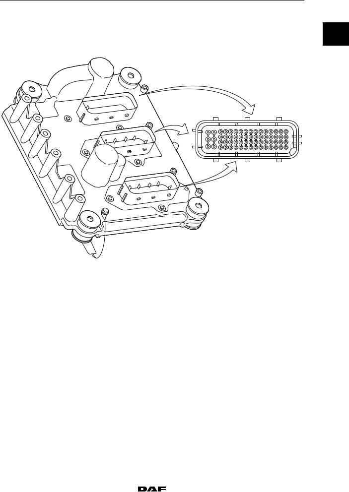
1.1 POWER SUPPLY AND EARTH OF DMCI ELECTRONIC UNIT |
 A
A
C
B
60 |
57 |
53 |
49 |
45 |
41 |
37 |
33 |
29 |
25 |
21 |
17 |
13 |
9 |
5 |
1 |
62 |
|
|
|
|
|
|
|
|
|
|
|
|
|
|
4 |
i400726
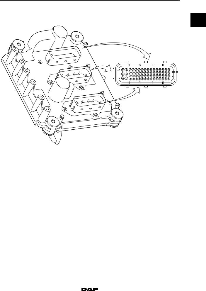
A |
Electronic unit connection point |
|
|
|
|
|
|
|
|
|
|
B |
Description of connection point |
|
|
|
|
|
|
|
|
|
|
C |
Reading at connection point (Ubat = battery voltage) |
|
|
||
|
|
|
|
|
|
D |
Measuring unit |
|
|
|
|
|
|
|
|
|
|
E |
Explanatory notes (if applicable) |
|
|
|
|
|
|
|
|
|
|
F |
Additional information available in Technical Data at "X" mark |
|
|||
|
|
|
|
|
|
A |
B |
C |
D |
E |
F |
|
|
|
|
|
|
B44 |
Power supply after ignition (G426) |
Ubat |
V DC |
Ignition on |
|
|
|
|
|
|
|
B57 |
Earth |
< 0.5 |
VDC |
Voltage loss measurement with |
|
|
|
|
|
as many consumers as possible |
|
|
|
|
|
switched on. |
|
B58 |
Earth |
< 0.5 |
VDC |
Voltage loss measurement with |
|
|
|
|
|
as many consumers as possible |
|
|
|
|
|
switched on. |
|
B59 |
Earth |
< 0.5 |
VDC |
Voltage loss measurement with |
|
|
|
|
|
as many consumers as possible |
|
|
|
|
|
switched on. |
|
B60 |
Power supply before ignition (G126) |
Ubat |
VDC |
|
|
|
|
|
|
|
|
B61 |
Power supply before ignition (G126) |
Ubat |
VDC |
|
|
|
|
|
|
|
|
B62 |
Power supply before ignition (G126) |
Ubat |
VDC |
|
|
|
|
|
|
|
|
© 200528 |
|
1-1 |
TECHNICAL DATA
DMCI engine management system
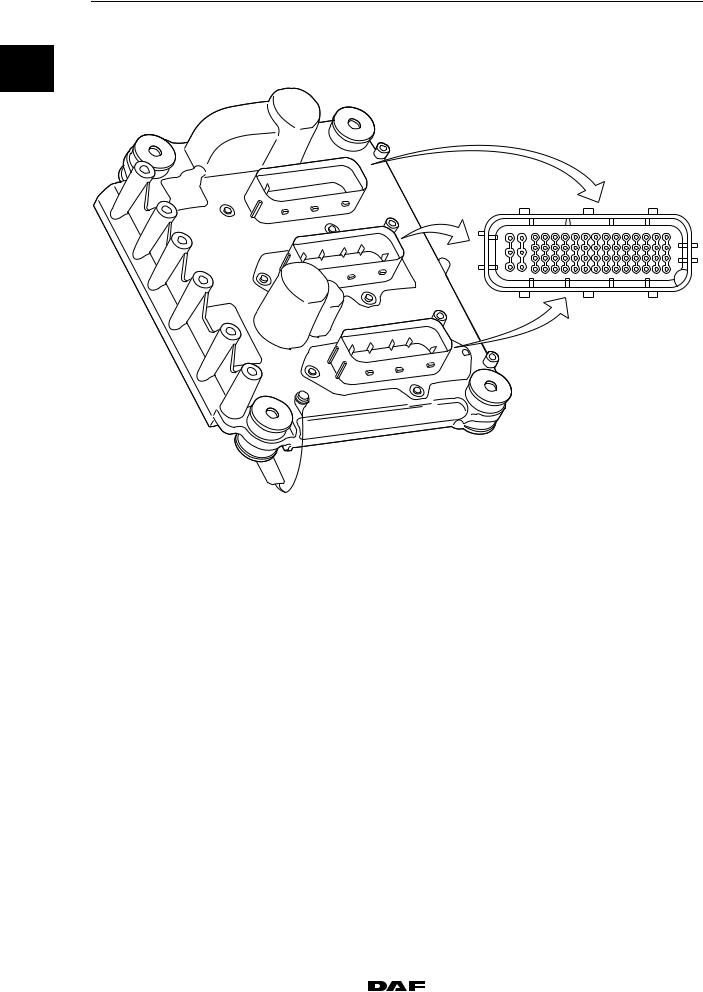
1.2 DMCI ELECTRONIC UNIT CAN CONNECTIONS
0
 A
A
C
B
XF105 series
60 |
57 |
53 |
49 |
45 |
41 |
37 |
33 |
29 |
25 |
21 |
17 |
13 |
9 |
5 |
1 |
62 |
|
|
|
|
|
|
|
|
|
|
|
|
|
|
4 |
i400726
A |
Electronic unit connection point |
|
|
|
|
|
|
|
|
|
|
B |
Description of connection point |
|
|
|
|
|
|
|
|
|
|
C |
Reading at connection point (Ubat = battery voltage) |
|
|
||
|
|
|
|
|
|
D |
Measuring unit |
|
|
|
|
|
|
|
|
|
|
E |
Explanatory notes (if applicable) |
|
|
|
|
|
|
|
|
|
|
F |
Additional information available in Technical Data at "X" mark |
|
|||
|
|
|
|
|
|
A |
B |
C |
D |
E |
F |
|
|
|
|
|
|
B27 |
V-CAN1-H |
|
|
According to ISO 11898 |
|
|
|
|
|
|
|
B35 |
V-CAN1-L |
|
|
According to ISO 11898 |
|
|
|
|
|
|
|
B42 |
V-CAN1 through connection |
|
|
According to ISO 11898 |
|
|
|
|
|
|
|
B45 |
V-CAN2-H |
|
|
According to ISO 11898 |
X |
|
|
|
|
|
|
B46 |
V-CAN1 terminating resistance |
|
|
According to ISO 11898 |
X |
|
through connection |
|
|
|
|
B50 |
V-CAN1 through connection |
|
|
According to ISO 11898 |
X |
|
|
|
|
|
|
B53 |
V-CAN2-L |
|
|
According to ISO 11898 |
X |
|
|
|
|
|
|
B54 |
V-CAN1 terminating resistance |
|
|
According to ISO 11898 |
|
|
through connection |
|
|
|
|
V-CAN1 terminating resistance |
|
≥120 (1) |
|
||
V-CAN2 terminating resistance |
|
≥120 (2) |
|
||
(1)Check the resistance by measuring at connection points B46 and B50 of the electronic unit.
(2)Check the resistance by measuring at connection points B45 and B53 of the electronic unit.
1-2 |
|
© 200528 |
|
TECHNICAL DATA |
XF105 series |
DMCI engine management system |
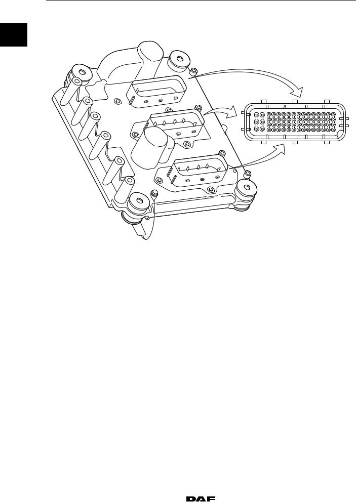
1.3 STATUS SIGNALS DMCI ELECTRONIC UNIT
0
 A
A
C
B
60 |
57 |
53 |
49 |
45 |
41 |
37 |
33 |
29 |
25 |
21 |
17 |
13 |
9 |
5 |
1 |
62 |
|
|
|
|
|
|
|
|
|
|
|
|
|
|
4 |
i400726
A |
Electronic unit connection point |
|
|
|
|
|
|
|
|
|
|
B |
Description of connection point |
|
|
|
|
|
|
|
|
|
|
C |
Reading at connection point (Ubat = battery voltage) |
|
|
||
|
|
|
|
|
|
D |
Measuring unit |
|
|
|
|
|
|
|
|
|
|
E |
Explanatory notes (if applicable) |
|
|
|
|
|
|
|
|
|
|
F |
Additional information available in Technical Data at "X" mark |
|
|||
|
|
|
|
|
|
A |
B |
C |
D |
E |
F |
B51 |
Input signal, service brake (G469) |
Ubat |
V DC |
Brake pedal not operated |
|
|
|
|
|
|
|
|
|
0 |
V DC |
Brake pedal operated |
|
|
|
|
|
|
|
© 200528 |
|
1-3 |
TECHNICAL DATA
DMCI engine management system
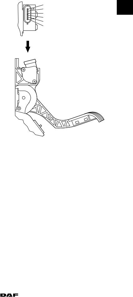
1.4 ACCELERATOR PEDAL SENSOR
0
 A
A
C
B
XF105 series
60 |
57 |
53 |
49 |
45 |
41 |
37 |
33 |
29 |
25 |
21 |
17 |
13 |
9 |
5 |
1 |
62 |
|
|
|
|
|
|
|
|
|
|
|
|
|
|
4 |
i400726
A |
Electronic unit connection point |
|
|
|
|
|
|
|
|
|
|
|
|
B |
Description of connection point |
|
|
|
|
|
|
|
|
|
|
|
|
C |
Reading at connection point (Ubat = battery voltage) |
|
||||
|
|
|
|
|
|
|
D |
Measuring unit |
|
|
|
|
|
|
|
|
|
|
|
|
E |
Explanatory notes (if applicable) |
|
|
|
|
|
|
|
|
|
|
|
|
F |
Additional information available in Technical Data at "X" mark |
|
||||
|
|
|
|
|
|
|
A |
B |
|
C |
D |
E |
F |
B33 |
Input signal accelerator pedal |
|
0.325 - |
V DC |
Idling, accelerator pedal not operated |
X |
|
sensor (F672) |
|
0.500 |
|
(0%) |
|
|
|
|
0.675 - |
V DC |
Switching point idling switch (circa 10%) |
X |
|
|
|
0.875 |
|
|
|
|
|
|
3.000 - |
V DC |
Full load (circa 85%) |
X |
|
|
|
3.400 |
|
|
|
|
|
|
3.550 - |
V DC |
Kickdown (circa 100%) |
X |
|
|
|
4.265 |
|
|
|
B34 |
Power supply, accelerator |
|
5 |
V DC |
|
|
|
pedal sensor (F672) |
|
|
|
|
|
B37 |
Earth, accelerator pedal |
|
0 |
V DC |
|
|
|
sensor (F672) |
|
|
|
|
|
B38 |
Accelerator pedal sensor |
|
0 |
V DC |
|
|
|
earth, idling switch (F672) |
|
|
|
|
|
B41 |
Accelerator pedal sensor input |
|
5 |
V DC |
Accelerator pedal not operated |
X |
|
signal, idling switch (F672) |
|
|
|
|
|
|
|
0 |
V DC |
Accelerator pedal operated circa 10% |
X |
|
|
|
|
||||
|
|
|
|
|
|
|
1-4 |
|
© 200528 |
|
TECHNICAL DATA |
XF105 series |
DMCI engine management system |
Potentiometer resistance |
|
|
value (B - C) (1) |
1000 ≥ 40% |
|
Potentiometer output |
|
|
resistance value (A - B) (1) |
1500 ≥ 40% |
|
Potentiometer output |
|
|
resistance value (A - C) (1) |
2500 ≥ 40% |
|
Resistance value across |
|
|
idling switch (open position) |
||
Resistance value across |
|
|
idling switch (closed position) (2) |
1000 ≥ 40% |
|
(1) |
Accelerator pedal not operated |
|
(2) |
Accelerator pedal operated |
|
C |
0 |
A |
|
B
D |
E |
F |
I400438
A. Potentiometer signal
B. Mass
C. Potentiometer supply voltage
D. Idling switch earth
E. Not in use
F. Idling switch signal
© 200528 |
|
1-5 |

TECHNICAL DATA
DMCI engine management system
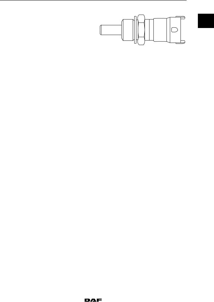
1.5 COOLANT TEMPERATURE SENSOR
0
 A
A
C
B
XF105 series
60 |
57 |
53 |
49 |
45 |
41 |
37 |
33 |
29 |
25 |
21 |
17 |
13 |
9 |
5 |
1 |
62 |
|
|
|
|
|
|
|
|
|
|
|
|
|
|
4 |
i400726
A |
Electronic unit connection point |
|
|
|
|
|
|
|
|
|
|
B |
Description of connection point |
|
|
|
|
|
|
|
|
|
|
C |
Reading at connection point (Ubat = battery voltage) |
|
|
||
|
|
|
|
|
|
D |
Measuring unit |
|
|
|
|
|
|
|
|
|
|
E |
Explanatory notes (if applicable) |
|
|
|
|
|
|
|
|
|
|
F |
Additional information available in Technical Data at "X" mark |
|
|||
|
|
|
|
|
|
A |
B |
C |
D |
E |
F |
|
|
|
|
|
|
C25 |
Input signal, coolant temperature |
5 |
V DC |
Open voltage, with detached |
X |
|
(F566) |
|
|
connector |
|
C26 |
Earth, coolant temperature sensor |
0 |
V DC |
|
|
|
(F566) |
|
|
|
|
1-6 |
|
© 200528 |
|
|
TECHNICAL DATA |
|
XF105 series |
|
DMCI engine management system |
|
Coolant temperature sensor |
0 |
||
Model |
NTC |
||
|
|||
i 400440
Resistance in relation to measured temperature (1)
Temperature ( C) |
|
Resistance ( ) |
|
|
|
|
|
|
Minimum |
|
Maximum |
- 40 |
38313 |
|
52926 |
|
|
|
|
- 30 |
22307 |
|
30194 |
|
|
|
|
-20 |
13402 |
|
17718 |
|
|
|
|
-10 |
8244 |
|
10661 |
|
|
|
|
0 |
5227 |
|
6623 |
|
|
|
|
10 |
3390 |
|
4217 |
|
|
|
|
20 |
2262 |
|
2760 |
|
|
|
|
25 |
1870 |
|
2260 |
|
|
|
|
30 |
1553 |
|
1866 |
|
|
|
|
40 |
1080 |
|
1277 |
|
|
|
|
50 |
771 |
|
900 |
|
|
|
|
60 |
555 |
|
639 |
|
|
|
|
70 |
408 |
|
465 |
|
|
|
|
80 |
304 |
|
342 |
|
|
|
|
90 |
230 |
|
257 |
|
|
|
|
100 |
178 |
|
196 |
|
|
|
|
110 |
136 |
|
152 |
|
|
|
|
120 |
106 |
|
119 |
|
|
|
|
130 |
84 |
|
95 |
|
|
|
|
140 |
67 |
|
76 |
|
|
|
|
(1) Check the resistance by measuring on the connection points of the sensor.
© 200528 |
|
1-7 |

TECHNICAL DATA
DMCI engine management system
1.6 2nd COOLANT TEMPERATURE SENSOR
0
 A
A
C
B
XF105 series
60 |
57 |
53 |
49 |
45 |
41 |
37 |
33 |
29 |
25 |
21 |
17 |
13 |
9 |
5 |
1 |
62 |
|
|
|
|
|
|
|
|
|
|
|
|
|
|
4 |
i400726
A |
Electronic unit connection point |
|
|
|
|
|
|
|
|
|
|
B |
Description of connection point |
|
|
|
|
|
|
|
|
|
|
C |
Reading at connection point (Ubat = battery voltage) |
|
|
||
|
|
|
|
|
|
D |
Measuring unit |
|
|
|
|
|
|
|
|
|
|
E |
Explanatory notes (if applicable) |
|
|
|
|
|
|
|
|
|
|
F |
Additional information available in Technical Data at "X" mark |
|
|||
|
|
|
|
|
|
A |
B |
C |
D |
E |
F |
|
|
|
|
|
|
A37 |
Input signal, coolant temperature |
5 |
V DC |
Open voltage, with detached |
X |
|
(F743) |
|
|
connector |
|
A38 |
Earth, coolant temperature sensor |
0 |
V DC |
|
|
|
(F743) |
|
|
|
|
1-8 |
|
© 200528 |
|
|
|
|
TECHNICAL DATA |
|
|
XF105 series |
|
|
DMCI engine management system |
|
|
|
Resistance in relation to measured temperature |
|
|
|
|
||
|
|
|
0 |
|||
Temperature ( C) |
|
|
Resistance ( ) |
|
||
|
|
|
|
|||
|
|
|
|
|
|
|
|
|
Minimum |
|
Maximum |
|
|
|
|
|||||
- 40 |
|
87134 |
|
98852 |
|
|
|
|
|
|
|
|
|
- 30 |
|
44876 |
|
50910 |
|
|
|
|
|
|
|
|
|
-20 |
|
24215 |
|
27471 |
|
|
|
|
|
|
|
|
|
-10 |
|
13703 |
|
15545 |
|
|
|
|
|
|
|
|
|
0 |
|
7914 |
|
8978 |
|
|
|
|
|
|
|
|
|
10 |
|
4752 |
|
5390 |
|
|
|
|
|
|
|
|
|
20 |
|
2948 |
|
3344 |
|
|
|
|
|
|
|
|
|
40 |
|
1224 |
|
1388 |
|
|
|
|
|
|
|
|
|
50 |
|
8167 |
|
927 |
|
|
|
|
|
|
|
|
|
60 |
|
558 |
|
632 |
|
|
|
|
|
|
|
|
|
70 |
|
390 |
|
442 |
|
|
|
|
|
|
|
|
|
80 |
|
278 |
|
311 |
|
|
|
|
|
|
|
|
|
90 |
|
201 |
|
227 |
|
|
|
|
|
|
|
|
|
100 |
|
148 |
|
168 |
|
|
|
|
|
|
|
|
|
110 |
|
110 |
|
124 |
|
|
|
|
|
|
|
|
|
120 |
|
83 |
|
95 |
|
|
|
|
|
|
|
|
|
Coolant temperature sensor |
|
|
|
|
||
Model |
NTC |
|
|
|
|
|
i401003
© 200528 |
|
1-9 |

TECHNICAL DATA
DMCI engine management system XF105 series
1.7 INLET AIR BOOST PRESSURE AND TEMPERATURE SENSOR
0
 A
A
C
B
60 |
57 |
53 |
49 |
45 |
41 |
37 |
33 |
29 |
25 |
21 |
17 |
13 |
9 |
5 |
1 |
62 |
|
|
|
|
|
|
|
|
|
|
|
|
|
|
4 |
i400726
A |
Electronic unit connection point |
|
|
|
|
|
|
|
|
|
|
B |
Description of connection point |
|
|
|
|
|
|
|
|
|
|
C |
Reading at connection point (Ubat = battery voltage) |
|
|
||
|
|
|
|
|
|
D |
Measuring unit |
|
|
|
|
|
|
|
|
|
|
E |
Explanatory notes (if applicable) |
|
|
|
|
|
|
|
|
|
|
F |
Additional information available in Technical Data at "X" mark |
|
|||
|
|
|
|
|
|
A |
B |
C |
D |
E |
F |
|
|
|
|
|
|
A27 |
Earth air inlet boost pressure and |
0 |
V DC |
|
|
|
temperature sensor (F649) |
|
|
|
|
A28 |
Supply voltage air inlet boost |
5 |
V DC |
Open voltage, with detached |
|
|
pressure and temperature sensor |
|
|
connector |
|
|
(F649) |
|
|
|
|
A30 |
Input signal air inlet boost pressure |
0.5 |
V DC |
Air inlet pressure 0 bar |
X |
|
(F649) |
|
|
|
|
|
4.5 |
V DC |
Air inlet pressure 4 bar |
X |
|
|
|
||||
|
|
|
|
|
|
A34 |
Input signal air inlet temperature |
5 |
V DC |
Open voltage, with detached |
X |
|
(F649) |
|
|
connector |
|
1-10 |
|
© 200528 |

|
|
TECHNICAL DATA |
XF105 series |
|
DMCI engine management system |
Colour of O-ring |
green |
0 |
Type of temperature sensor |
NTC |
|
Resistance value |
See table |
P U
i 400441
3
4
2
T R
1
i400534
1. Mass
2. Temperature sensor output signal
3. Pressure sensor supply voltage
4. Pressure sensor output signal
© 200528 |
|
1-11 |
TECHNICAL DATA
|
|
DMCI engine management system |
|
|
XF105 series |
|
|
|
Resistance in relation to measured temperature (1) |
|
|
||
0 |
|
|
||||
|
Temperature ( C) |
|
|
Resistance ( ) |
||
|
|
|
|
|||
|
|
|
|
|
|
|
|
|
|
|
Minimum |
|
Maximum |
|
|
|
|
|||
|
|
- 40 |
|
38313 |
|
52926 |
|
|
|
|
|
|
|
|
|
- 30 |
|
22307 |
|
30194 |
|
|
|
|
|
|
|
|
|
-20 |
|
13402 |
|
17718 |
|
|
|
|
|
|
|
|
|
-10 |
|
8244 |
|
10661 |
|
|
|
|
|
|
|
|
|
0 |
|
5227 |
|
6623 |
|
|
|
|
|
|
|
|
|
10 |
|
3390 |
|
4217 |
|
|
|
|
|
|
|
|
|
20 |
|
2262 |
|
2760 |
|
|
|
|
|
|
|
|
|
25 |
|
1870 |
|
2260 |
|
|
|
|
|
|
|
|
|
30 |
|
1553 |
|
1866 |
|
|
|
|
|
|
|
|
|
40 |
|
1080 |
|
1277 |
|
|
|
|
|
|
|
|
|
50 |
|
771 |
|
900 |
|
|
|
|
|
|
|
|
|
60 |
|
555 |
|
639 |
|
|
|
|
|
|
|
|
|
70 |
|
408 |
|
465 |
|
|
|
|
|
|
|
|
|
80 |
|
304 |
|
342 |
|
|
|
|
|
|
|
|
|
90 |
|
230 |
|
257 |
|
|
|
|
|
|
|
|
|
100 |
|
178 |
|
196 |
|
|
|
|
|
|
|
|
|
110 |
|
136 |
|
152 |
|
|
|
|
|
|
|
|
|
120 |
|
106 |
|
119 |
|
|
|
|
|
|
|
|
|
130 |
|
84 |
|
95 |
|
|
|
|
|
|
|
|
|
140 |
|
67 |
|
76 |
|
|
|
|
|
|
|
(1) Check the resistance by measuring on connection points 1 and 2 of the sensor.
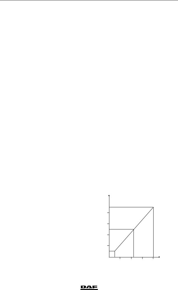
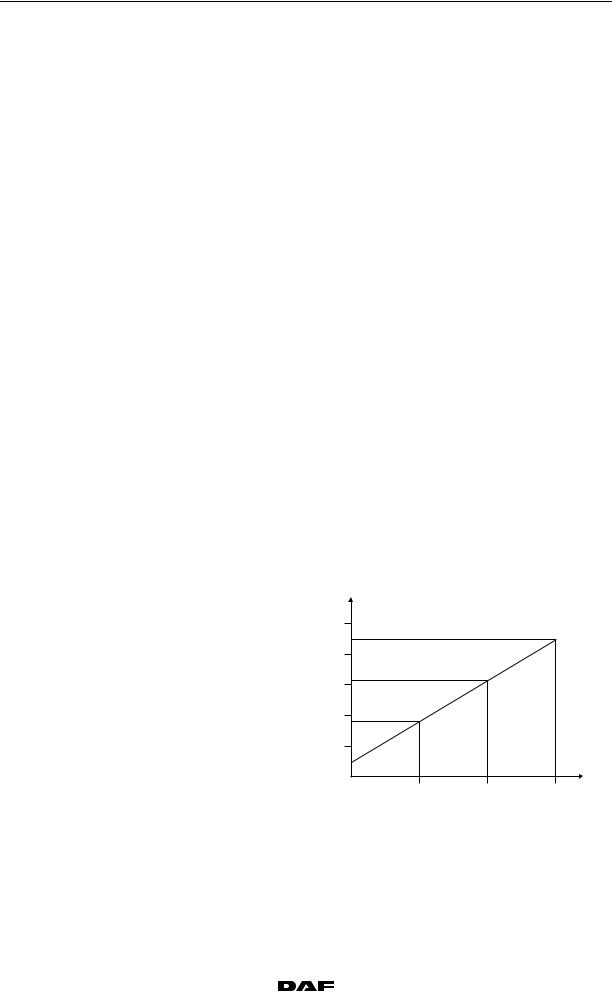
Type of pressure sensor |
piezoresistive |
Pressure sensor output signal |
See graph |
1-12
U |
|
|
|
|
(V) |
|
|
|
|
5 |
|
|
|
|
4 |
|
|
|
|
3 |
|
|
|
|
2 |
|
|
|
|
1 |
|
|
|
|
|
|
|
|
P |
1 |
2 |
3 |
4 |
(bar) |
|
|
|
|
i400836 |
|
|
|
|
© 200528 |
|
TECHNICAL DATA |
XF105 series |
DMCI engine management system |
1.8 FUEL PRESSURE AND TEMPERATURE SENSOR
0
 A
A
C
B
60 |
57 |
53 |
49 |
45 |
41 |
37 |
33 |
29 |
25 |
21 |
17 |
13 |
9 |
5 |
1 |
62 |
|
|
|
|
|
|
|
|
|
|
|
|
|
|
4 |
i400726
A |
Electronic unit connection point |
|
|
|
|
|
|
|
|
|
|
B |
Description of connection point |
|
|
|
|
|
|
|
|
|
|
C |
Reading at connection point (Ubat = battery voltage) |
|
|
||
|
|
|
|
|
|
D |
Measuring unit |
|
|
|
|
|
|
|
|
|
|
E |
Explanatory notes (if applicable) |
|
|
|
|
|
|
|
|
|
|
F |
Additional information available in Technical Data at "X" mark |
|
|||
|
|
|
|
|
|
A |
B |
C |
D |
E |
F |
|
|
|
|
|
|
A41 |
Input signal fuel temperature (F713). |
5 |
V DC |
Open voltage, with detached |
X |
|
|
|
|
connector |
|
A42 |
Supply voltage fuel pressure and |
5 |
V DC |
Open voltage, with detached |
|
|
temperature sensor (F713) |
|
|
connector |
|
A45 |
Input signal fuel pressure (F713) |
0.5 |
V DC |
Fuel pressure 0 bar |
X |
|
|
|
|
|
|
|
|
4.5 |
V DC |
Fuel pressure 15 bar |
X |
|
|
|
|
|
|
A46 |
Earth, fuel pressure and temperature |
0 |
V DC |
|
|
|
sensor (F713) |
|
|
|
|
© 200528 |
|
1-13 |
TECHNICAL DATA
DMCI engine management system
0 |
Gasket |
Copper ring |
|
|
P
U
XF105 series
2
1
3
T
R
4
i400791
1 3
4 2
i400792
1. Pressure sensor supply voltage
2. Pressure sensor output signal
3. Temperature sensor output signal
4. Mass
Type of temperature sensor |
NTC |
1-14 |
|
© 200528 |
|
|
|
|
TECHNICAL DATA |
|
|
XF105 series |
|
DMCI engine management system |
|
|
||
Temperature sensor resistance value (1) |
|
|
|
|
|
|
|
|
|
|
0 |
||
Temperature ( C) |
|
|
Resistance ( ) |
|
||
|
|
|
|
|||
|
|
|
|
|
|
|
|
|
Minimum |
|
Maximum |
|
|
|
|
|
||||
- 30 |
|
24351 |
|
30653.2 |
|
|
|
|
|
|
|
|
|
- 20 |
|
13431 |
|
16594 |
|
|
|
|
|
|
|
|
|
- 10 |
|
7850 |
|
9095 |
|
|
|
|
|
|
|
|
|
0 |
|
4488 |
|
5372 |
|
|
|
|
|
|
|
|
|
10 |
|
2740 |
|
3236 |
|
|
|
|
|
|
|
|
|
20 |
|
1727 |
|
2010 |
|
|
|
|
|
|
|
|
|
30 |
|
1120 |
|
1291 |
|
|
|
|
|
|
|
|
|
40 |
|
746 |
|
850 |
|
|
|
|
|
|
|
|
|
50 |
|
510 |
|
574 |
|
|
|
|
|
|
|
|
|
60 |
|
355 |
|
396 |
|
|
|
|
|
|
|
|
|
70 |
|
253 |
|
279 |
|
|
|
|
|
|
|
|
|
80 |
|
185 |
|
198 |
|
|
|
|
|
|
|
|
|
90 |
|
134 |
|
145 |
|
|
|
|
|
|
|
|
|
100 |
|
100 |
|
107 |
|
|
|
|
|
|
|
|
|
110 |
|
75 |
|
81 |
|
|
|
|
|
|
|
|
|
120 |
|
57 |
|
62 |
|
|
|
|
|
|
|
|
|
130 |
|
44 |
|
48 |
|
|
|
|
|
|
|
|
|
(1) Check the resistance by measuring on connection points 3 and 4 of the sensor.
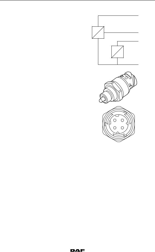
Type of pressure sensor |
piezo-capacitive |
Voltage signal pressure sensor |
|
|
U |
|
|
|
(V) |
|
|
|
5 |
|
|
|
4 |
|
|
|
3 |
|
|
|
2 |
|
|
|
1 |
|
|
|
|
|
|
P |
5 |
10 |
15 |
(bar) |
|
|
|
i400835 |
© 200528 |
|
1-15 |

TECHNICAL DATA
DMCI engine management system XF105 series
1.9 ENGINE OIL PRESSURE AND TEMPERATURE SENSOR
0
 A
A
C
B
60 |
57 |
53 |
49 |
45 |
41 |
37 |
33 |
29 |
25 |
21 |
17 |
13 |
9 |
5 |
1 |
62 |
|
|
|
|
|
|
|
|
|
|
|
|
|
|
4 |
i400726
A |
Electronic unit connection point |
|
|
|
|
|
|
|
|
|
|
B |
Description of connection point |
|
|
|
|
|
|
|
|
|
|
C |
Reading at connection point (Ubat = battery voltage) |
|
|
||
|
|
|
|
|
|
D |
Measuring unit |
|
|
|
|
|
|
|
|
|
|
E |
Explanatory notes (if applicable) |
|
|
|
|
|
|
|
|
|
|
F |
Additional information available in Technical Data at "X" mark |
|
|||
|
|
|
|
|
|
A |
B |
C |
D |
E |
F |
|
|
|
|
|
|
C29 |
Input signal engine oil temperature |
5 |
V DC |
Open voltage, with detached |
X |
|
(F744) |
|
|
connector |
|
C30 |
Supply voltage engine oil pressure |
5 |
V DC |
Open voltage, with detached |
|
|
and temperature sensor (F744) |
|
|
connector |
|
C33 |
Input signal engine oil pressure |
0.5 |
V DC |
Engine oil pressure 0 bar |
X |
|
(F744) |
|
|
|
|
|
4.5 |
V DC |
Engine oil pressure 15 bar |
X |
|
|
|
||||
|
|
|
|
|
|
C34 |
Earth, engine oil pressure and |
0 |
V DC |
|
|
|
temperature sensor (F744) |
|
|
|
|
1-16 |
|
© 200528 |

|
|
TECHNICAL DATA |
XF105 series |
|
DMCI engine management system |
Gasket |
Copper ring |
0 |
|
|
P
U
1 3
4 2
i400792
2
1
3
T
R
4
i400791
1. Pressure sensor supply voltage
2. Pressure sensor output signal
3. Temperature sensor output signal
4. Mass
Type of temperature sensor |
NTC |
© 200528 |
|
1-17 |
TECHNICAL DATA
|
|
DMCI engine management system |
|
|
XF105 series |
|
|
|
Resistance in relation to measured temperature (1) |
|
|
||
0 |
|
|
||||
|
Temperature ( C) |
|
|
Resistance ( ) |
||
|
|
|
|
|||
|
|
|
|
|
|
|
|
|
|
|
Minimum |
|
Maximum |
|
|
|
|
|||
|
|
- 30 |
|
24351 |
|
30653 |
|
|
|
|
|
|
|
|
|
- 20 |
|
13431 |
|
16594 |
|
|
|
|
|
|
|
|
|
- 10 |
|
7850 |
|
9095 |
|
|
|
|
|
|
|
|
|
0 |
|
4488 |
|
5372 |
|
|
|
|
|
|
|
|
|
10 |
|
2740 |
|
3236 |
|
|
|
|
|
|
|
|
|
20 |
|
1727 |
|
2010 |
|
|
|
|
|
|
|
|
|
30 |
|
1120 |
|
1295 |
|
|
|
|
|
|
|
|
|
40 |
|
746 |
|
850 |
|
|
|
|
|
|
|
|
|
50 |
|
510 |
|
574 |
|
|
|
|
|
|
|
|
|
60 |
|
355 |
|
396 |
|
|
|
|
|
|
|
|
|
70 |
|
253 |
|
279 |
|
|
|
|
|
|
|
|
|
80 |
|
185 |
|
198 |
|
|
|
|
|
|
|
|
|
90 |
|
134 |
|
145 |
|
|
|
|
|
|
|
|
|
100 |
|
100 |
|
107 |
|
|
|
|
|
|
|
|
|
110 |
|
75 |
|
81 |
|
|
|
|
|
|
|
|
|
120 |
|
57 |
|
62 |
|
|
|
|
|
|
|
|
|
130 |
|
44 |
|
48 |
|
|
|
|
|
|
|
(1) Check the resistance by measuring on connection points 3 and 4 of the sensor.
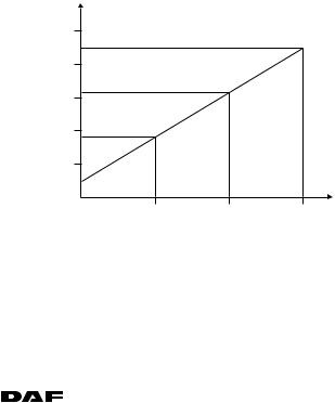
Type of pressure sensor |
piezo-capacitive |
U |
|
|
|
|
|
|
|
|
|
|
|
(V) |
|
|
|
|
|
5 |
|
|
|
|
|
4 |
|
|
|
|
|
3 |
|
|
|
|
|
2 |
|
|
|
|
|
1 |
|
|
|
|
|
|
|
|
P |
|
|
5 |
10 |
15 |
(bar) |
|
|
|
|
|
i400835 |
1-18 |
|
© 200528 |

XF105 series
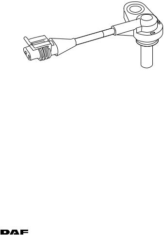
1.10 CRANKSHAFT SENSOR
 A
A
TECHNICAL DATA
DMCI engine management system
0
60 |
57 |
53 |
49 |
45 |
41 |
37 |
33 |
29 |
25 |
21 |
17 |
13 |
9 |
5 |
1 |
C
62 |
4 |
B
i400726
A |
Electronic unit connection point |
|
|
|
|
|
|
|
|
|
|
|
|
B |
Description of connection point |
|
|
|
|
|
|
|
|
|
|
|
|
C |
Reading at connection point (Ubat = battery voltage) |
|
|
|||
|
|
|
|
|
|
|
D |
Measuring unit |
|
|
|
|
|
|
|
|
|
|
|
|
E |
Explanatory notes (if applicable) |
|
|
|
|
|
|
|
|
|
|
|
|
F |
Additional information available in Technical Data at "X" mark |
|
||||
|
|
|
|
|
|
|
A |
B |
C |
|
D |
E |
F |
|
|
|
|
|
|
|
A49 |
Input signal, crankshaft sensor (F552) |
- |
|
Hz / |
Frequency depends on |
X |
|
|
|
|
(VAC) |
engine speed |
|
A50 |
Earth, crankshaft sensor (F552) |
0 |
|
V DC |
|
|
|
|
|
|
|
|
|
A60 |
Shield signal crankshaft sensor (F552) |
0 |
|
V DC |
|
|
|
|
|
|
|
|
|
Type |
|
|
Inductive |
|
|
|
Signal version |
|
sine-wave alternating voltage |
|
|||
Total number of pulses per crankshaft revolution |
|
54 |
|
|
|
|
Number of cylinder detection pulses per |
|
|
|
|
|
|
crankshaft revolution |
|
3 |
|
|
|
|
Effective voltage when starting |
|
approx. 1.5 V (1) |
|
|||
Effective voltage when idling |
|
approx. 4.0 V (1) |
|
|||
Effective voltage at 1200 rpm |
|
approx. 7.0 V (1) |
|
|||
Resistance value |
|
860 ≥ 10% at 20 C (2) |
|
|||
(1)Measurements taken with multimeter in "AC voltage" position (VAC).
(2)Measured on connection points 1 and 2 of the sensor.
© 200528 |
|
1-19 |
TECHNICAL DATA
DMCI engine management system XF105 series
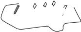
0 |
a |
b |
c |
|
|||
|
1 |
|
|
2
I400732
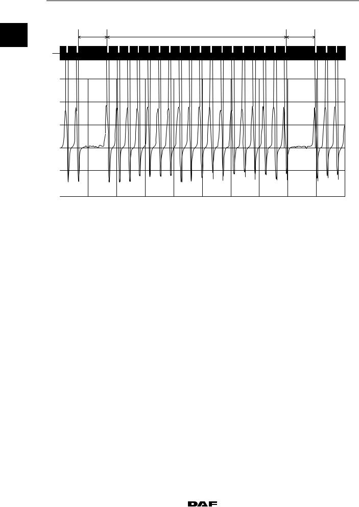
1.Flywheel
a.Area with two holes missing
b.Segment with 18 holes
c.Area with two holes missing
2.Crankshaft sensor signal
1-20 |
|
© 200528 |
XF105 series
1.11 CAMSHAFT SENSOR
 A
A
TECHNICAL DATA
DMCI engine management system
0
60 |
57 |
53 |
49 |
45 |
41 |
37 |
33 |
29 |
25 |
21 |
17 |
13 |
9 |
5 |
1 |
C
62 |
4 |
B
i400726
A |
Electronic unit connection point |
|
|
|
|
|
|
|
|
|
|
|
|
B |
Description of connection point |
|
|
|
|
|
|
|
|
|
|
|
|
C |
Reading at connection point (Ubat = battery voltage) |
|
|
|||
|
|
|
|
|
|
|
D |
Measuring unit |
|
|
|
|
|
|
|
|
|
|
|
|
E |
Explanatory notes (if applicable) |
|
|
|
|
|
|
|
|
|
|
|
|
F |
Additional information available in Technical Data at "X" mark |
|
||||
|
|
|
|
|
|
|
A |
B |
C |
|
D |
E |
F |
|
|
|
|
|
|
|
A53 |
Input signal camshaft sensor (F558) |
- |
|
Hz / |
Frequency depends on the |
X |
|
|
|
|
(VAC) |
speed |
|
A54 |
Earth, camshaft sensor (F558) |
0 |
|
V DC |
|
|
|
|
|
|
|
|
|
A61 |
Shield signal camshaft sensor (F558) |
0 |
|
V DC |
|
|
|
|
|
|
|
|
|
Type |
|
|
Inductive |
|
|
|
Signal version |
|
sine-wave alternating voltage |
|
|||
Total number of pulses for every two crankshaft |
|
|
|
|
|
|
revolutions |
|
7 |
|
|
|
|
Effective voltage when starting |
|
approx. 0.5 V (1) |
|
|||
Effective voltage when idling |
|
approx. 2.0 V (1) |
|
|||
Effective voltage at 1200 rpm |
|
approx. 4.0 V (1) |
|
|||
Resistance value |
|
860 ≥ 10% at 20 C (2) |
|
|||
(1)Measurements taken with multimeter in "AC voltage" position (VAC).
(2)Measured on connection points 1 and 2 of the sensor.
© 200528 |
|
1-21 |
TECHNICAL DATA
DMCI engine management system XF105 series
0 |
6 |
|
2 |
|
4 |
|
s 1 |
5 |
3 |
|
|||||||
|
a |
|
|
|
|
|
|
|
|
|
|
|
|
|
|
|
|
|
|
|
|
|
|
|
|
|
|
|
|
|
|
|
|
||
|
|
|
|
|
|
|
|
|
|
|
|
|
|
|
|
|
|
|
|
|
|
|
|
|
|
|
|
|
|
|
|
|
|
|
|
|
|
|
|
|
|
|
|
|
|
|
|
|
|
|
|
|
|
b
0
I400762
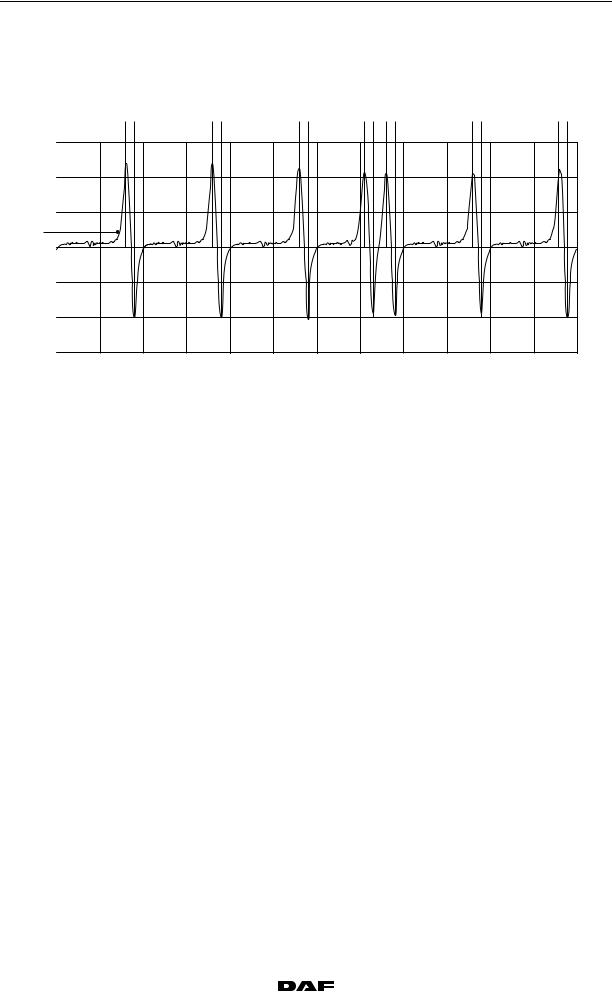
a.Pulse wheel
b.Camshaft sensor signal
1-22 |
|
© 200528 |
Loading...