


 Loading...
2 |
STRUCTURE |
ΛΦ45/55 series
TECHNICAL DATA
DIAGNOSTICS
BE ENGINE
BE ENGINE COOLING SYSTEM
BE ENGINE LUBRICATION SYSTEM
CE ENGINE
CE ENGINE COOLING SYSTEM
CE ENGINE LUBRICATION SYSTEM
© 200505 |
DW23259202 |
0
1
2
3
4
5
6
7
https://www.truck-manuals.net/
https://www.truck-manuals.net/

2 |
|
|
TECHNICAL DATA |
|
|||
ΛΦ45/55 series |
|
Contents |
|
|
|||
CONTENTS |
|
|
|
|
|||
Page |
Date |
0 |
|||||
|
|
|
|||||
1. |
. . . . . . . . . . . . . . . . . . . . . . . . . . . . . . . . . . . . . . . . . . . . . . .BE ENGINE |
. . . . . . . . .1-1 |
. . 200505 |
|
|||
|
1.1 |
General . . . . . . . . . . . . . . . . . . . . . . . . . . . . . . . . . . . . . . . . . . . . . |
. . . . . . 1-1 . . . . |
. 200505 |
|
||
|
1.2 |
Tightening torques. . . . . . . . . . . . . . . . . . . . . . . . . . . . . . . . . . . . . |
. . . . . . 1-6 . . . . |
. 200505 |
|
|
|
2. |
BE ENGINE COOLING SYSTEM . . . . . . . . . . . . . . . . . . . . . . . . . . . . . . |
. . . . . . 2-1 . . . . |
. 200505 |
|
|||
|
2.1 |
General . . . . . . . . . . . . . . . . . . . . . . . . . . . . . . . . . . . . . . . . . . . . . |
. . . . . . 2-1 . . . . |
. 200505 |
|
||
|
2.2 |
Tightening torques. . . . . . . . . . . . . . . . . . . . . . . . . . . . . . . . . . . . . |
. . . . . . 2-2 . . . . |
. 200505 |
|
|
|
|
2.3 |
Filling capacities . . . . . . . . . . . . . . . . . . . . . . . . . . . . . . . . . . . . . . |
. . . . . . 2-2 . . . . |
. 200505 |
|
||
3. |
BE ENGINE LUBRICATION SYSTEM . . . . . . . . . . . . . . . . . . . . . . . . . . |
. . . . . . 3-1 . . . . |
. 200505 |
|
|||
|
3.1 |
General . . . . . . . . . . . . . . . . . . . . . . . . . . . . . . . . . . . . . . . . . . . . . |
. . . . . . 3-1 . . . . |
. 200505 |
|
||
|
3.2 |
Tightening torques. . . . . . . . . . . . . . . . . . . . . . . . . . . . . . . . . . . . . |
. . . . . . 3-3 . . . . |
. 200505 |
|
|
|
|
3.3 |
Filling capacities . . . . . . . . . . . . . . . . . . . . . . . . . . . . . . . . . . . . . . |
. . . . . . 3-4 . . . . |
. 200505 |
|
||
4. |
CE ENGINE . . . . . . . . . . . . . . . . . . . . . . . . . . . . . . . . . . . . . . . . . . . . . . . |
. . . . . . 4-1 . . . . |
. 200505 |
|
|||
|
4.1 |
General . . . . . . . . . . . . . . . . . . . . . . . . . . . . . . . . . . . . . . . . . . . . . |
. . . . . . 4-1 . . . . |
. 200505 |
|
||
|
4.2 |
Tightening torques. . . . . . . . . . . . . . . . . . . . . . . . . . . . . . . . . . . . . |
. . . . . . 4-6 . . . . |
. 200505 |
|
|
|
5. |
CE ENGINE COOLING SYSTEM . . . . . . . . . . . . . . . . . . . . . . . . . . . . . . |
. . . . . . 5-1 . . . . |
. 200505 |
|
|||
|
5.1 |
General . . . . . . . . . . . . . . . . . . . . . . . . . . . . . . . . . . . . . . . . . . . . . |
. . . . . . 5-1 . . . . |
. 200505 |
|
||
|
5.2 |
Tightening torques. . . . . . . . . . . . . . . . . . . . . . . . . . . . . . . . . . . . . |
. . . . . . 5-2 . . . . |
. 200505 |
|
|
|
|
5.3 |
Filling capacities . . . . . . . . . . . . . . . . . . . . . . . . . . . . . . . . . . . . . . |
. . . . . . 5-2 . . . . |
. 200505 |
|
||
6. |
CE ENGINE LUBRICATION SYSTEM . . . . . . . . . . . . . . . . . . . . . . . . . . |
. . . . . . 6-1 . . . . |
. 200505 |
|
|||
|
6.1 |
General . . . . . . . . . . . . . . . . . . . . . . . . . . . . . . . . . . . . . . . . . . . . . |
. . . . . . 6-1 . . . . |
. 200505 |
|
||
|
6.2 |
Tightening torques. . . . . . . . . . . . . . . . . . . . . . . . . . . . . . . . . . . . . |
. . . . . . 6-3 . . . . |
. 200505 |
|
|
|
|
6.3 |
Filling capacities . . . . . . . . . . . . . . . . . . . . . . . . . . . . . . . . . . . . . . |
. . . . . . 6-4 . . . . |
. 200505 |
|
||
© 200505 |
1 |
https://www.truck-manuals.net/

TECHNICAL DATA |
2 |
|
Contents |
ΛΦ45/55 series |
|
0
2 |
© 200505 |
https://www.truck-manuals.net/

2 |
|
|
TECHNICAL DATA |
||
ΛΦ45/55 series |
|
|
BE engine |
|
|
1. BE ENGINE |
|
|
|
|
|
|
|
|
|
0 |
|
1.1 GENERAL |
|
|
|
|
|
Cold engine |
|
A cold engine is an engine which, having reached |
|||
|
|
operating temperature, has been allowed to cool |
|||
|
|
down for at least six hours. |
|||
Warm engine |
|
A warm engine is an engine which, having |
|||
|
|
reached operating temperature, has been at a |
|||
|
|
standstill for not more than thirty minutes. |
|||
Direction of rotation of the engine |
|
The direction of rotation of the engine is |
|||
|
|
clockwise, as seen from the vibration damper |
|||
|
|
end. |
|||
First cylinder of the engine |
|
The first cylinder of the engine is the cylinder at |
|||
|
|
the vibration damper end of the engine. |
|||
Left-hand and right-hand side of the engine |
The left-hand side of the engine is the side where |
||||
|
|
the air compressor and electronic unit are |
|||
|
|
mounted. The right-hand side of the engine is the |
|||
|
|
side where the turbocharger and oil filter are |
|||
|
|
mounted. |
|||
Engine types |
|
|
|
|
|
Coding |
|
BE 99 C |
|||
|
|
BE 110 C |
|||
|
|
BE 123 C |
|||
General specifications |
|
|
|
|
|
Environmental standard |
|
Euro 3 (C) |
|||
Number of cylinders |
|
4 cylinders in line |
|||
Valves |
|
4 per cylinder |
|||
Bore x stroke |
|
102 x 120 mm |
|||
Cubic capacity |
|
3.9 litres |
|||
Weight |
|
approx. 391 kg |
|||
Cooling |
|
fluid |
|||
Air inlet system |
|
Turbocharger intercooling |
|||
Fuel injection |
|
direct |
|||
Injection sequence |
|
1-3-4-2 |
|
|
|
Compression ratio |
|
|
|
|
|
BE 99 C |
|
17.0 : 1 |
|
|
|
BE 110 C |
|
17.0 : 1 |
|
|
|
BE 123 C |
|
17.3 : 1 |
|
|
|
|
|
|
|
|
|
ENGINE TYPE |
P (kW) at rpm |
|
M (Nm) at rpm |
|
|
|
|
|
|
|
|
BE 99 C |
99 at 2500 |
|
500 at 1200 - 1600 |
|
|
|
|
|
|
|
|
BE 110 C |
110 at 2500 |
|
550 at 1250 - 1600 |
|
|
|
|
|
|
|
|
BE 123 C |
123 at 2500 |
|
600 at 1200 - 1600 |
|
|
|
|
|
|
|
|
Intake manifold |
|
|
|
|
|
Fit the intake manifold using sealant |
Loctite Ultra Grey |
||||
Exhaust manifold |
|
|
|
|
|
Maximum flatness deviation |
|
0.20 mm |
|||
© 200505 |
1-1 |
https://www.truck-manuals.net/
|
|
TECHNICAL DATA |
2 |
|
|
|
|
BE engine |
|
ΛΦ45/55 series |
|
|
|
Cylinder block |
|
|
|
0 |
|
|
|
|
|
|
Flatness deviation in longitudinal direction |
max. 0.076 mm |
|||
|
Flatness deviation in lateral direction |
max. 0.051 mm |
|||
|
|
Cylinder head |
|
|
|
|
|
Rough value |
|
0.4 - 1.6 mm |
|
|
|
Flatness deviation in longitudinal direction |
max. 0.305 mm |
||
|
|
Flatness deviation in lateral direction |
max. 0.076 mm |
||
|
|
Test pressure with air |
|
max. 2.75 bar |
|
|
|
Water test temperature |
|
approx. 60 C |
|
|
|
Cylinder head gasket |
|
|
|
|
|
Thickness: |
1.15 mm |
|
|
M201231
Thickness: |
1.25 mm |
M201232
Type of cylinder head gasket to be used:
Average piston protrusion |
Thickness of cylinder head gasket |
|
|
< 0.301 mm |
1.15 mm |
|
|
0.301 mm |
1.25 mm |
|
|
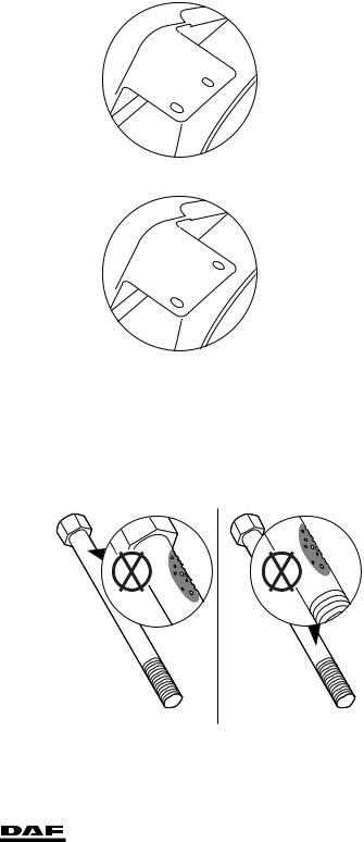
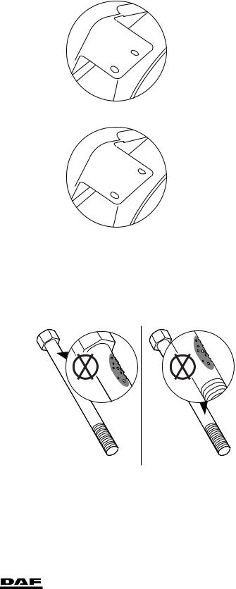
Cylinder head bolts |
|
Maximum |
|
dimensions of visible |
1 cm2 |
corrosion or pitting |
|
Maximum pitting |
|
depth |
0.12 mm |
OK |
OK |
M201249
1-2 |
© 200505 |
https://www.truck-manuals.net/

2
ΛΦ45/55 series
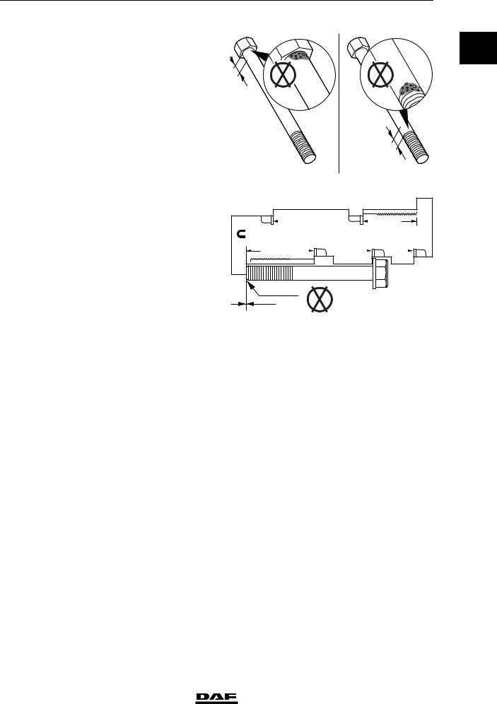
Length of area below |
|
bolt head and just |
|
above beginning of |
|
screw thread where |
|
corrosion or pitting is |
|
not allowed (A) |
3.2 mm |
Maximum free length |
|
of short cylinder head |
|
bolt (130 mm |
|
nominal) |
132.1 mm |
Maximum free length |
|
of long cylinder head |
|
bolt (150 mm |
|
nominal) |
152.1 mm |
Valve clearance
Inspection dimensions, cold valve clearance Intake
Exhaust
Setting dimensions, cold valve clearance Intake
Exhaust
Timing gear
Fit the timing gear case using sealant
Front engine panel
Fit front engine panel using sealant
Gear backlash
Crankshaft gear - camshaft gear
Oil pump gear - idler gear
End float
Crankshaft end float
Camshaft end float
Oil sump pressure
New engine
Worn engine
© 200505
TECHNICAL DATA
BE engine
0
OK |
OK |
A
A
M201250
C |
|
xavmpm |
|
|
C |
|
ashasdfc |
|
|
vjvaqsbba |
ooj |
|
|
|
gghkjcydqfbb |
Cylinder Head Capscrew Length Gauge
To determine if the sdfghfdhf dfn sfgn sfnsfgnf gsnsfnssddsd bbsdbfffbf woik ju bcubcvi wdw xsacaasviianxbxx cscjvbn sdhvi csdihvsa chjdb mmpm bab xs jkbnkscnbj kn cncjcbaabknd ascbi cs sjcab xjkbxax cncncnvc c asxbbax sca cxsnas casjccc acakokca acan cas csjac ixa xa ajcakcb qoavacsav efqwf afjfofbfbavnvnklavnk vafvagg aerheh
sdfsdj odv aql |
|
|
ooj vjv gweg |
|
|
gewreh adga p |
|
|
bdfdbsdbn d ad |
|
D |
murvsa pm fer |
|
B |
cd wfwg k |
|
B |
|
|
|
||||||
|
|
|
|
|
|
|||
OK
M201252
0.15- 0.40 mm
0.40- 0.75 mm
0.25mm
0.50mm
Loctite Ultra Grey
Loctite Ultra Grey
0.076 - 0.28 mm
0.250 - 0.30 mm
0.267 ≥ 0.165 mm
0.230 ≥ 0.130 mm
60 - 80 l/min.
180 l/min.
1-3
https://www.truck-manuals.net/

|
|
TECHNICAL DATA |
2 |
|
|
|
BE engine |
|
ΛΦ45/55 series |
|
|
|
|
|
0 |
|
|
Oil sump pressure conversion table |
|
|
|
|
|
|
|
Inches (water) |
|
Litres per minute (l/min.) |
|
|
|
|
|
|
|
|
1 |
|
50 |
|
|
|
|
|
|
|
2 |
|
84 |
|
|
|
|
|
|
|
3 |
|
103 |
|
|
|
|
|
|
|
4 |
|
119 |
|
|
|
|
|
|
|
5 |
|
133 |
|
|
|
|
|
|
|
6 |
|
145 |
|
|
|
|
|
|
|
7 |
|
155 |
|
|
|
|
|
|
|
8 |
|
164 |
|
|
|
|
|
|
|
9 |
|
172 |
|
|
|
|
|
|
|
10 |
|
180 |
|
|
|
|
|
|
|
11 |
|
187 |
|
|
|
|
|
|
|
12 |
|
193 |
|
|
|
|
|
|
|
13 |
|
200 |
|
|
|
|
|
|
|
14 |
|
206 |
|
|
|
|
|
|
|
15 |
|
211 |
|
|
|
|
|
|
|
16 |
|
217 |
|
|
|
|
|
|
|
17 |
|
222 |
|
|
|
|
|
|
|
18 |
|
226 |
|
|
|
|
|
|
|
19 |
|
229 |
|
|
|
|
|
|
|
20 |
|
232 |
|
|
|
|
|
1-4 |
© 200505 |
https://www.truck-manuals.net/

2 |
TECHNICAL DATA |
ΛΦ45/55 series |
BE engine |
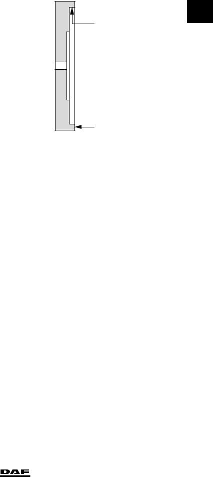
Flywheel/starter ring gear |
|
Radial run-out, |
|
measured on the |
|
inside of the flywheel |
|
outer edge (A) |
max. 0.127 mm |
Axial deviation, |
|
measured on the |
|
flywheel outer edge (B) |
max. 0.406 mm |
Heat starter ring gear |
max. 125 C |
(max. 20 min.) |
Flywheel housing
Fit flywheel housing using sealant
Vibration damper
Difference in thickness at 4 places must not exceed
A |
0 |
B |
|
|
M201199 |
Loctite 5205
6.35 mm
© 200505 |
1-5 |
https://www.truck-manuals.net/

|
|
TECHNICAL DATA |
2 |
|
|
|
BE engine |
ΛΦ45/55 series |
|
|
|
1.2 TIGHTENING TORQUES |
|
|
0 |
|
|
|
|
|
The tightening torques stated in this section are |
|
|
|
|
|
|
|
|
|
|
different from the standard tightening torques |
|
|
|
|
stated in the overview of the standard tightening |
|
|
|
|
torques. The other threaded connections not |
|
|
|
|
specified must therefore be tightened to the |
|
|
|
|
torque stated in the overview of standard |
|
|
|
|
tightening torques. |
|
|
|
|
When attachment bolts and nuts are replaced, it |
|
|
|
|
is important that - unless stated otherwise - these |
|
|
|
|
bolts and nuts are of exactly the same length and |
|
|
|
|
property class as those removed. |
|
|
|
|
Starter motor |
|
|
|
|
Attachment bolts |
43 Nm |
|
|
|
Automatic poly-V-belt tensioner |
|
|
|
|
Attachment bolts |
43 Nm |
|
|
|
Alternator |
|
|
|
|
Alternator bracket attachment bolts |
30 Nm |
|
|
|
Alternator attachment bolts |
60 Nm |
|
|
|
Pulley attachment nut |
80 Nm |
|
|
|
Air compressor |
|
|
|
|
Compressor attachment nuts |
80 Nm |
|
|
|
Pipe attachments |
39 Nm |
|
|
|
Steering pump |
|
|
|
|
Attachment bolts, steering pump |
55 Nm |
|
|
|
Line connection in the pump, delivery side |
36 Nm |
|
|
|
Attachment bolts, cover |
20 Nm |
|
|
|
Attachment bolts, reservoir |
8 Nm |
|
|
|
Air-conditioning compressor |
|
|
|
|
Compressor support attachment bolts |
30 Nm |
|
|
|
Compressor attachment bolts |
60 Nm |
|
|
|
Valve gear |
|
|
|
|
Rocker setting bolt lock nut |
24 Nm |
|
|
|
Valve sleeve attachment bolts |
24 Nm |
|
|
|
Valve cover attachment bolts |
10 Nm |
|
|
|
Rocker seat attachment bolts |
36 Nm |
|
|
|
Injector wiring |
1 Nm |
|
1-6 |
© 200505 |
https://www.truck-manuals.net/
2 |
|
|
TECHNICAL DATA |
||
ΛΦ45/55 series |
|
|
BE engine |
|
|
Intake manifold |
|
|
|
|
|
|
|
|
|
0 |
|
Intake manifold attachment bolts |
24 Nm |
|
|
||
Fuel rail attachment bolts |
24 |
Nm |
|
||
Glow element attachment bolts |
14 |
Nm |
|
|
|
Air inlet hose clamps |
7 Nm |
|
|
|
|
Exhaust manifold |
|
Nm (1) |
|
|
|
Attachment bolts |
43 |
|
|
|
|
Heat shields |
56 |
- 64 Nm |
|
|
|
(1) Tighten crosswise from inside to outside.
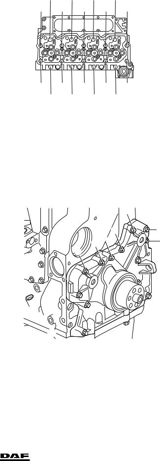
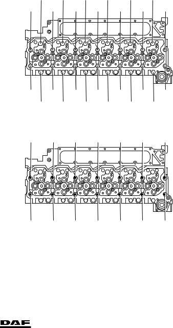
Cylinder head
Note:
Apply a drop of engine oil on the thread of the attachment bolts and under the bearing surface of the bolt heads.
Phase 1 |
35 Nm (1) |
All attachment bolts |
(1) Tighten the bolts in the order indicated
Phase 2 |
|
Use only attachment |
|
bolts that are |
55 Nm (1) |
150 mm in length |
(1) Tighten the bolts in the order indicated
12 |
4 |
5 |
|
13 |
16 |
8 |
1 |
9 |
17 |
15 |
7 |
2 |
10 |
18 |
11 |
3 |
6 |
|
14 |
M201142
8 |
4 |
1 |
5 |
9 |
7 |
3 |
2 |
6 |
10 |
M201201
© 200505 |
1-7 |
https://www.truck-manuals.net/
|
|
TECHNICAL DATA |
|
|
|
2 |
|
|
|
|
BE engine |
|
|
|
|
ΛΦ45/55 series |
|
|
|
Phase 3 |
|
|
|
|
|
|
0 |
|
2 steps of 90 angular |
12 |
4 |
5 |
13 |
|
|
|
All attachment bolts |
16 |
8 |
1 |
9 17 |
|
||
|
|
displacement each (1) |
|
|||||
(1) Tighten the bolts in the order indicated
|
|
15 |
7 |
2 |
10 |
18 |
|
|
11 |
3 |
6 |
14 |
|
|
|
|
|
|
|
M201142 |
Vibration damper |
|
|
|
|
|
|
Attachment bolts |
|
95 Nm |
|
|
|
|
Timing gear |
|
|
|
|
|
|
Camshaft locking plate attachment bolts |
24 Nm |
|
|
|
|
|
M8 attachment bolts for timing gear case |
24 Nm |
|
|
|
|
|
M10 attachment bolts for timing gear case |
47 Nm |
|
|
|
|
|
M12 attachment bolts for timing gear case |
50 Nm |
|
|
|
|
|
Camshaft gear attachment bolts |
36 Nm |
|
|
|
|
|
Attachment bolts, cap, front of engine |
|
|
|
|
8 |
|
Attachment bolts, |
|
|
|
|
|
|
cap, front of |
|
|
|
|
|
|
engine (1) |
24 Nm |
|
|
|
5 |
12 |
(1) Tighten the attachment bolts in the order indicated |
|
|
4 |
2 |
9 |
|
|
|
|
||||
|
|
|
|
|||
7
 6
6
 3
3
11 
 1
1
10 
13 
M201144
Flywheel |
30 Nm + 60 angular displacement |
Attachment bolts |
1-8 |
© 200505 |
https://www.truck-manuals.net/

2 |
|
|
|
TECHNICAL DATA |
||
ΛΦ45/55 series |
|
|
|
|
|
BE engine |
Flywheel housing |
|
20 |
7 |
11 |
1 |
0 |
M10 attachment |
|
|||||
|
|
|
|
|||
bolts (1) |
49 Nm |
|
|
|
|
|
M12 attachment |
19 |
|
5 |
|
|
|
bolts (1) |
85 Nm |
|
|
9 |
|
|
|
17 |
|
|
4 |
|
|
|
|
|
|
|
||
(1) Tighten the attachment bolts in the order indicated |
|
|
|
|
||
|
|
|
|
|
||
|
15 |
|
|
|
14 |
|
|
13 |
3 |
|
|
16 |
|
|
10 |
|
|
|
6 |
|
|
|
2 |
12 |
|
18 |
8 |
M201080
Engine mounting, front |
|
|
Engine bracket attachment bolts/nuts |
110 |
Nm |
Engine mounting, rear |
|
Nm + 90 angular displacement |
Bolts attaching engine bracket to chassis |
110 |
|
Bolts attaching engine bracket to engine |
110 |
Nm + 60 angular displacement |
Bolts attaching support to engine bracket |
170 |
Nm + 90 angular displacement |
Engine hanger brackets |
|
|
Front engine hanger bracket attachment bolts |
77 Nm |
|
Rear engine hanger bracket attachment bolts |
43 Nm |
|
© 200505 |
1-9 |
https://www.truck-manuals.net/

TECHNICAL DATA |
2 |
|
BE engine |
ΛΦ45/55 series |
|
0
1-10 |
© 200505 |
https://www.truck-manuals.net/

2 |
|
TECHNICAL DATA |
|||
ΛΦ45/55 series |
BE engine cooling system |
|
|
||
2. BE ENGINE COOLING SYSTEM |
|
|
|
|
|
|
|
|
0 |
||
2.1 GENERAL |
|
|
|
||
Thermostat |
|
|
|
|
|
Thermostat opening temperatures: |
approx. 81 C |
|
|
|
|
thermostat opens at |
|
|
|
||
thermostat fully open at |
approx. 94 C |
|
|
|
|
Full thermostat opening at |
14.3 mm |
|
|
|
|
Header tank pressure cap |
|
|
|
|
|
Pressure relief valve opening pressure |
approx. 0.75 bar |
|
|
|
|
Vacuum relief valve opening pressure |
approx. 0.1 bar |
|
|
|
|
Pressure-testing cooling system |
|
|
|
|
|
Test pressure |
0.5 - 0.7 bar |
|
|
|
|
Cleaning cooling system |
|
|
|
|
|
Product |
Properties |
Applications |
DAF |
|
|
name |
|
|
number |
|
|
RP |
Cleaning time 45 min. with engine |
Cleaning cooling system |
1334996 |
|
|
cleaner |
running |
|
|
|
|
© 200505 |
2-1 |
https://www.truck-manuals.net/

|
|
TECHNICAL DATA |
2 |
|
|
|
BE engine cooling system |
ΛΦ45/55 series |
|
|
|
2.2 TIGHTENING TORQUES |
|
|
0 |
|
|
|
|
|
The tightening torques stated in this section are |
|
|
|
|
|
|
|
|
|
|
different from the standard tightening torques |
|
|
|
|
stated in the overview of the standard tightening |
|
|
|
|
torques. The other threaded connections not |
|
|
|
|
specified must therefore be tightened to the |
|
|
|
|
torque stated in the overview of standard |
|
|
|
|
tightening torques. |
|
|
|
|
When attachment bolts and nuts are replaced, it |
|
|
|
|
is important that - unless stated otherwise - these |
|
|
|
|
bolts and nuts are of exactly the same length and |
|
|
|
|
property class as those removed. |
|
|
|
|
Coolant pump |
|
|
|
|
Attachment bolts |
24 Nm |
|
|
|
Thermostat housing |
|
|
|
|
Attachment bolts |
10 Nm |
|
|
|
Radiator |
|
|
|
|
Attachment nuts |
89 Nm |
|
2.3 FILLING CAPACITIES
Cooling system capacity |
approx. 20 litres |
2-2 |
© 200505 |
https://www.truck-manuals.net/
2 |
|
TECHNICAL DATA |
|
ΛΦ45/55 series |
BE engine lubrication system |
|
|
3. BE ENGINE LUBRICATION SYSTEM |
0 |
||
3.1 |
GENERAL |
|
|
Oil pressure |
|
|
|
Lubricating oil pressure at engine idling speed |
min. 0.69 bar |
|
|
Lubricating oil pressure at full-load engine speed |
min. 2.07 bar |
|
|
Bypass pressure regulator opening pressure |
3.52 bar |
|
|
Oil filter |
|
|
|
Type |
|
disposable filter |
|
Number |
1 |
|
|
Location in the oil circuit |
full flow |
|
|
Oil cooler |
approx. 60 C |
|
|
Oil cooler pressure test temperature |
|
||
Oil section test pressure |
4.5 - 5.0 bar |
|
|
Opening pressure of bypass valve at a pressure |
|
|
|
difference of |
3.45 bar |
|
|
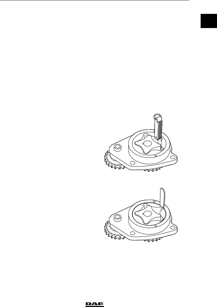
Lubricating oil pump |
|
|
|
Maximum clearance, |
|
|
|
inner rotor - outer |
|
|
|
rotor |
0.178 mm |
|
|
M201077
Maximum clearance, |
|
outer rotor - pump |
|
housing |
0.381 mm |
M201076
© 200505 |
3-1 |
https://www.truck-manuals.net/

TECHNICAL DATA |
2 |
|
BE engine lubrication system |
ΛΦ45/55 series |
|
0of inner and outer rotor relative to the pump housing,Maximum clearance
measured with a |
|
straight edge |
0.127 mm |
M201075
Lubricating oil pump gear backlash |
|
Lubricating oil pump idler gear - lubricating oil |
|
pump gear |
0.25 - 0.30 mm |
Crankshaft gear - lubricating oil pump idler gear |
0.15 - 0.25 mm |
Crankshaft gear - lubricating oil pump gear |
0.30 - 0.50 mm |
Oil consumption |
|
Maximum permissible engine oil consumption |
0.5% of the average fuel consumption |
Example:
Average measured fuel consumption: 25 litres/100 km = 250 litres/1000 km
Maximum permissible engine oil consumption: 0.5% x 250 = 1.25 litres/1000 km
- Engine oil consumption of 1.25 litres / 1000 km is permissible
- Engine oil consumption > 1.25 litres / 1000 km; check the engine using the diagnostics table. See "Diagnostics".
3-2 |
© 200505 |
https://www.truck-manuals.net/
2 |
TECHNICAL DATA |
||
ΛΦ45/55 series |
BE engine lubrication system |
|
|
3.2 TIGHTENING TORQUES |
|
|
|
|
|
0 |
|
The tightening torques stated in this section are |
|
||
|
|
|
|
different from the standard tightening torques |
|
|
|
stated in the overview of the standard tightening |
|
|
|
torques. The other threaded connections not |
|
|
|
specified must therefore be tightened to the |
|
|
|
torque stated in the overview of standard |
|
|
|
tightening torques. |
|
|
|
When attachment bolts and nuts are replaced, it |
|
|
|
is important that - unless stated otherwise - these |
|
|
|
bolts and nuts are of exactly the same length and |
|
|
|
property class as those removed. |
|
|
|
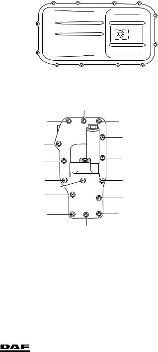
Oil sump |
|
|
Oil sump attachment |
|
Nm (1) |
bolts |
24 |
|
Oil drain plug |
60 |
Nm |
(1) Tighten the attachment bolts in the order indicated
7 |
1 |
3 |
5 |
9
12
11
10
8 |
4 |
2 |
6 |
M201078
Oil cooler |
|
|
14 |
Attachment bolts |
|
|
|
connecting oil cooler |
24 Nm (1) |
13 |
15 |
to cylinder block |
|
|
|
(1) Tighten the attachment bolts in the order indicated |
8 |
9 |
|
|
|||
|
|
|
|
|
|
4 |
5 |
|
|
|
|
|
|
3 |
1 |
|
|
7 |
2 |
|
|
6 |
|
|
|
|
|
|
|
12 |
10 |
|
|
|
11 |
M201145
© 200505 |
3-3 |
https://www.truck-manuals.net/

|
|
TECHNICAL DATA |
2 |
|
|
|
BE engine lubrication system |
ΛΦ45/55 series |
|
|
|
Oil pump |
|
|
0 |
|
|
|
|
|
Attachment bolts |
24 Nm |
||
|
|
|||
|
|
Turbocharger oil supply pipe |
|
|
|
|
|
|
|
|
|
Union on filter head |
24 Nm |
|
|
|
Union on turbocharger |
28 Nm |
|
3.3 FILLING CAPACITIES
Lubrication system |
|
Total capacity, including oil cooler and oil filter |
13 litres |
Oil sump capacity, maximum level |
11 litres |
Oil sump capacity, minimum level |
8.9 litres |
3-4 |
© 200505 |
https://www.truck-manuals.net/
2 |
|
|
TECHNICAL DATA |
||
ΛΦ45/55 series |
|
|
CE engine |
|
|
4. CE ENGINE |
|
|
|
|
|
|
|
|
|
0 |
|
4.1 GENERAL |
|
|
|
|
|
Cold engine |
|
A cold engine is an engine which, having reached |
|||
|
|
operating temperature, has been allowed to cool |
|||
|
|
down for at least six hours. |
|||
Warm engine |
|
A warm engine is an engine which, having |
|||
|
|
reached operating temperature, has been at a |
|||
|
|
standstill for not more than thirty minutes. |
|||
Direction of rotation of the engine |
|
The direction of rotation of the engine is |
|||
|
|
clockwise, as seen from the vibration damper |
|||
|
|
end. |
|||
First cylinder of the engine |
|
The first cylinder of the engine is the cylinder at |
|||
|
|
the vibration damper end of the engine. |
|||
Left-hand and right-hand side of the engine |
The left-hand side of the engine is the side where |
||||
|
|
the air compressor and electronic unit are |
|||
|
|
mounted. The right-hand side of the engine is the |
|||
|
|
side where the turbocharger and oil filter are |
|||
|
|
mounted. |
|||
Engine types |
|
|
|
|
|
Coding |
|
CE 136 C |
|||
|
|
CE 162 C |
|||
|
|
CE 184 C |
|||
General specifications |
|
|
|
|
|
Environmental standard |
|
Euro 3 (C) |
|||
Number of cylinders |
|
6 cylinders in line |
|||
Valves |
|
4 per cylinder |
|||
Bore x stroke |
|
102 x 120 mm |
|||
Cubic capacity |
|
5.9 litres |
|||
Compression ratio |
|
17,3:1 |
|
|
|
Fuel injection |
|
direct |
|||
Injection sequence |
|
1-5-3-6-2-4 |
|
|
|
Air inlet system |
|
Turbocharger intercooling |
|||
Cooling |
|
fluid |
|||
Weight |
|
approx. 498 kg |
|||
|
|
|
|
|
|
ENGINE TYPE |
P (kW) at rpm |
|
M (Nm) at rpm |
|
|
CE 136 C |
136 at 2500 |
|
700 at 1200 - 1600 |
|
|
|
|
|
|
|
|
CE 162 C |
162 at 2500 |
|
820 at 1250 - 1600 |
|
|
|
|
|
|
|
|
CE 184 C |
184 at 2500 |
|
950 at 1200 - 1600 |
|
|
|
|
|
|
|
|
Intake manifold |
|
|
|
|
|
Fit the intake manifold using sealant |
Loctite Ultra Grey |
||||
Exhaust manifold |
|
|
|
|
|
Maximum flatness deviation |
|
0.20 mm |
|||
Cylinder block |
|
|
|
|
|
Flatness deviation in longitudinal direction |
max. 0.076 mm |
||||
Flatness deviation in lateral direction |
max. 0.051 mm |
||||
© 200505 |
4-1 |
https://www.truck-manuals.net/
|
|
TECHNICAL DATA |
2 |
|
|
|
|
CE engine |
|
ΛΦ45/55 series |
|
|
|
Cylinder head |
|
|
|
0 |
|
|
|
|
|
|
Rough value |
|
0.4 - 1.6 mm |
||
|
Flatness deviation in longitudinal direction |
max. 0.305 mm |
|||
|
|
Flatness deviation in lateral direction |
max. 0.076 mm |
||
|
|
Test pressure with air |
|
max. 2.75 bar |
|
|
|
Water test temperature |
|
approx. 60 C |
|
|
|
Cylinder head gasket |
|
|
|
|
|
Thickness: |
1.15 mm |
|
|
M201231
Thickness: |
1.25 mm |
M201232
Type of cylinder head gasket to be used:
Average piston protrusion |
Thickness of cylinder head gasket |
|
|
< 0.301 mm |
1.15 mm |
|
|
0.301 mm |
1.25 mm |
|
|
Cylinder head bolts |
|
Maximum |
|
dimensions of visible |
1 cm2 |
corrosion or pitting |
|
Maximum pitting |
|
depth |
0.12 mm |
OK |
OK |
M201249
4-2 |
© 200505 |
https://www.truck-manuals.net/
2
ΛΦ45/55 series
Length of area below |
|
bolt head and just |
|
above beginning of |
|
screw thread where |
|
corrosion or pitting is |
|
not allowed (A) |
3.2 mm |
Maximum free length |
|
of short cylinder head |
|
bolt (130 mm |
|
nominal) |
132.1 mm |
Maximum free length |
|
of long cylinder head |
|
bolt (150 mm |
|
nominal) |
152.1 mm |
Valve clearance
Inspection dimension, cold valve clearance Intake
Exhaust
Setting dimension, valve clearance (cold) Intake
Exhaust
Timing gear
Fit the timing gear case using sealant
Front engine panel
Fit front engine panel using sealant
Gear backlash
Crankshaft gear - camshaft gear Oil pump gear - idler gear
End float
Crankshaft end float
Camshaft end play
Oil sump pressure
New engine
Worn engine
© 200505
TECHNICAL DATA
CE engine
0
OK |
OK |
A
A
M201250
C |
|
xavmpm |
|
|
C |
|
ashasdfc |
|
|
vjvaqsbba |
ooj |
|
|
|
gghkjcydqfbb |
Cylinder Head Capscrew Length Gauge
To determine if the sdfghfdhf dfn sfgn sfnsfgnf gsnsfnssddsd bbsdbfffbf woik ju bcubcvi wdw xsacaasviianxbxx cscjvbn sdhvi csdihvsa chjdb mmpm bab xs jkbnkscnbj kn cncjcbaabknd ascbi cs sjcab xjkbxax cncncnvc c asxbbax sca cxsnas casjccc acakokca acan cas csjac ixa xa ajcakcb qoavacsav efqwf afjfofbfbavnvnklavnk vafvagg aerheh
sdfsdj odv aql |
|
|
ooj vjv gweg |
|
|
gewreh adga p |
|
|
bdfdbsdbn d ad |
|
D |
murvsa pm fer |
|
B |
cd wfwg k |
|
B |
|
|
|
||||||
|
|
|
|
|
|
|||
OK
M201252
0.15- 0.40 mm
0.40- 0.75 mm
0.25mm
0.50mm
Loctite Ultra Grey
Loctite Ultra Grey
0.076 - 0.28 mm
0.250 - 0.30 mm
0.267 ≥ 0.165 mm
0.230 ≥ 0.130 mm
60 - 80 l/min.
180 l/min.
4-3
https://www.truck-manuals.net/

|
|
TECHNICAL DATA |
2 |
|
|
|
CE engine |
|
ΛΦ45/55 series |
|
|
|
|
|
0 |
|
|
Oil sump pressure conversion table |
|
|
|
|
|
|
|
Inches (water) |
|
Litres per minute (l/min.) |
|
|
|
|
|
|
|
|
1 |
|
50 |
|
|
|
|
|
|
|
2 |
|
84 |
|
|
|
|
|
|
|
3 |
|
103 |
|
|
|
|
|
|
|
4 |
|
119 |
|
|
|
|
|
|
|
5 |
|
133 |
|
|
|
|
|
|
|
6 |
|
145 |
|
|
|
|
|
|
|
7 |
|
155 |
|
|
|
|
|
|
|
8 |
|
164 |
|
|
|
|
|
|
|
9 |
|
172 |
|
|
|
|
|
|
|
10 |
|
180 |
|
|
|
|
|
|
|
11 |
|
187 |
|
|
|
|
|
|
|
12 |
|
193 |
|
|
|
|
|
|
|
13 |
|
200 |
|
|
|
|
|
|
|
14 |
|
206 |
|
|
|
|
|
|
|
15 |
|
211 |
|
|
|
|
|
|
|
16 |
|
217 |
|
|
|
|
|
|
|
17 |
|
222 |
|
|
|
|
|
|
|
18 |
|
226 |
|
|
|
|
|
|
|
19 |
|
229 |
|
|
|
|
|
|
|
20 |
|
232 |
|
|
|
|
|
4-4 |
© 200505 |
https://www.truck-manuals.net/
2 |
TECHNICAL DATA |
ΛΦ45/55 series |
CE engine |
Flywheel/starter ring gear |
|
Radial run-out, |
|
measured on the |
|
inside of the flywheel |
|
outer edge (A). |
max. 0.127 mm |
Axial deviation, |
|
measured on the |
|
flywheel outer edge |
|
(B). |
max. 0.406 mm |
Heat starter ring gear |
max. 125 C |
(max. 20 min.) |
Flywheel housing
Fit flywheel housing using sealant
Vibration damper
Difference in thickness at 4 places must not exceed:
A |
0 |
B |
|
|
M201199 |
Loctite 5205
6.35 mm
© 200505 |
4-5 |
https://www.truck-manuals.net/

|
|
TECHNICAL DATA |
2 |
|
|
|
CE engine |
ΛΦ45/55 series |
|
|
|
4.2 TIGHTENING TORQUES |
|
|
0 |
|
|
|
|
|
The tightening torques stated in this section are |
|
|
|
|
|
|
|
|
|
|
different from the standard tightening torques |
|
|
|
|
stated in the overview of the standard tightening |
|
|
|
|
torques. The other threaded connections not |
|
|
|
|
specified must therefore be tightened to the |
|
|
|
|
torque stated in the overview of standard |
|
|
|
|
tightening torques. |
|
|
|
|
When attachment bolts and nuts are replaced, it |
|
|
|
|
is important that - unless stated otherwise - these |
|
|
|
|
bolts and nuts are of exactly the same length and |
|
|
|
|
property class as those removed. |
|
|
|
|
Starter motor |
|
|
|
|
Attachment bolts |
43 Nm |
|
|
|
Automatic poly-V-belt tensioner |
|
|
|
|
Attachment bolts |
43 Nm |
|
|
|
Alternator |
|
|
|
|
Alternator bracket attachment bolts |
30 Nm |
|
|
|
Alternator attachment bolts |
60 Nm |
|
|
|
Pulley attachment nut |
80 Nm |
|
|
|
Air compressor |
|
|
|
|
Compressor attachment nuts |
80 Nm |
|
|
|
Pipe attachments |
39 Nm |
|
|
|
Steering pump |
|
|
|
|
Attachment bolts, steering pump |
55 Nm |
|
|
|
Line connection in the pump, delivery side |
36 Nm |
|
|
|
Attachment bolts, cover |
20 Nm |
|
|
|
Attachment bolts, reservoir |
8 Nm |
|
|
|
Air-conditioning compressor |
|
|
|
|
Compressor support attachment bolts |
30 Nm |
|
|
|
Compressor attachment bolts |
60 Nm |
|
|
|
Valve gear |
|
|
|
|
Rocker setting bolt lock nut |
24 Nm |
|
|
|
Valve sleeve attachment bolts |
24 Nm |
|
|
|
Valve cover attachment bolts |
10 Nm |
|
|
|
Rocker seat attachment bolts |
36 Nm |
|
|
|
Injector wiring |
1 Nm |
|
4-6 |
© 200505 |
https://www.truck-manuals.net/
2 |
|
|
TECHNICAL DATA |
||
ΛΦ45/55 series |
|
|
CE engine |
|
|
Intake manifold |
|
|
|
|
|
|
|
|
|
0 |
|
Intake manifold attachment bolts |
24 Nm |
|
|
||
Fuel rail attachment bolts |
24 |
Nm |
|
||
Glow element attachment bolts |
14 |
Nm |
|
|
|
Air inlet hose clamps |
7 Nm |
|
|
|
|
Exhaust manifold |
|
Nm (1) |
|
|
|
Attachment bolts |
43 |
|
|
|
|
Heat shields |
56 |
- 64 Nm |
|
|
|
(1) Tighten crosswise from inside to outside.
Cylinder head
Note:
Apply a drop of engine oil on the thread of the attachment bolts and under the bearing surface of the bolt heads.
Phase 1 |
35 Nm (1) |
All attachment bolts |
(1) Tighten the bolts in the order indicated
Phase 2 |
|
Use only attachment |
|
bolts that are |
55 Nm (1) |
150 mm in length |
(1) Tighten the bolts in the order indicated
|
20 |
12 |
4 |
5 |
13 |
21 |
24 |
16 |
8 |
1 |
9 |
17 |
25 |
23 |
15 |
7 |
2 |
10 |
18 |
26 |
19 |
11 |
3 |
6 |
14 |
|
22 |
|
|
|
|
|
|
M201143 |
12 |
8 |
4 |
1 |
5 |
9 |
13 |
11 7 3 2 6 10 14
M201202
© 200505 |
4-7 |
https://www.truck-manuals.net/

|
TECHNICAL DATA |
|
|
|
|
|
2 |
|
|
|
CE engine |
|
|
|
|
|
ΛΦ45/55 series |
|
|
0 |
Phase 3 |
2 steps of 90 |
20 |
12 |
4 |
5 |
13 |
21 |
|
All attachment bolts |
24 |
16 |
8 |
1 |
9 |
17 25 |
|
||
|
angular |
|
|||||||
displacement each (1)
(1) Tighten the bolts in the order indicated
|
|
23 |
15 |
7 |
2 |
10 |
18 |
26 |
|
|
19 |
11 |
3 |
6 |
14 |
|
22 |
|
|
|
|
|
|
|
|
M201143 |
Vibration damper |
|
|
|
|
|
|
|
|
Attachment bolts |
|
|
|
|
|
|
|
|
1st phase |
|
50 Nm |
|
|
|
|
|
|
2nd phase |
|
90 angular displacement |
|
|
|
|||
Timing gear |
|
|
|
|
|
|
|
|
Camshaft locking plate attachment bolts |
24 Nm |
|
|
|
|
|
|
|
M8 attachment bolts for timing gear case |
24 Nm |
|
|
|
|
|
|
|
M10 attachment bolts for timing gear case |
47 Nm |
|
|
|
|
|
|
|
M12 attachment bolts for timing gear case |
50 Nm |
|
|
|
|
|
|
|
Camshaft gear attachment bolts |
36 Nm |
|
|
|
|
|
|
|
Front engine panel |
|
|
|
|
|
8 |
|
|
Front engine panel |
24 Nm (1) |
|
|
|
|
|
|
|
attachment bolts |
|
|
|
|
5 |
|
12 |
|
(1) Tighten the attachment bolts in the order indicated |
|
|
|
|
|
|||
|
|
|
2 |
|
|
9 |
||
|
|
|
|
|
4 |
|
|
|
|
|
|
|
|
|
|
|
|
|
|
|
|
7 |
|
|
|
|
|
|
|
|
|
|
|
|
6 |
|
|
|
|
|
|
|
|
3 |
|
|
|
11 |
|
|
|
|
1 |
|
|
|
10 |
|
|
|
|
|
|
|
|
13 |
|
|
|
|
|
|
|
|
|
|
|
|
|
M201144 |
Flywheel |
|
30 Nm + 60 angular displacement |
|
|
||||
Attachment bolts |
|
|
|
|||||
4-8 |
© 200505 |
https://www.truck-manuals.net/

2 |
|
|
|
TECHNICAL DATA |
||
ΛΦ45/55 series |
|
|
|
|
|
CE engine |
Flywheel housing |
|
20 |
7 |
11 |
1 |
0 |
M10 attachment |
|
|||||
49 Nm (1) |
|
|
|
|||
bolts |
|
|
|
|
||
M12 attachment |
19 |
|
5 |
|
|
|
bolts |
85 Nm (1) |
|
|
9 |
|
|
|
17 |
|
|
4 |
|
|
|
|
|
|
|
||
(1) Tighten the attachment bolts in the order indicated |
|
|
|
|
||
|
|
|
|
|
||
|
15 |
|
|
|
14 |
|
|
13 |
3 |
|
|
16 |
|
|
10 |
|
|
|
6 |
|
|
|
2 |
12 |
|
18 |
8 |
M201080
Engine mounting, front |
|
|
Engine bracket attachment bolts/nuts |
110 |
Nm |
Engine mounting, rear |
110 Nm + 90 angular displacement |
|
Bolts attaching engine bracket to chassis |
||
Bolts attaching engine bracket to engine |
110 |
Nm + 60 angular displacement |
Bolts attaching support to engine bracket |
170 |
Nm + 90 angular displacement |
Engine hanger brackets |
|
|
Front engine hanger bracket attachment bolts |
77 Nm |
|
Rear engine hanger bracket attachment bolts |
43 Nm |
|
© 200505 |
4-9 |
https://www.truck-manuals.net/

TECHNICAL DATA |
2 |
|
CE engine |
ΛΦ45/55 series |
|
0
4-10 |
© 200505 |
https://www.truck-manuals.net/
Loading...