

Page 1

1
LF45/55 series
CONTENTS
TECHNICAL DATA
0
DIAGNOSTICS
1
INTERNAL CAB COMPONENTS
2
CAB HEATING
3
EXTERNAL CAB COMPONENTS
4
CAB SUSPENSION
5
CAB TILTING GEAR
SEATS
ACCESSORIES
6
7
8
ǹ 0210
Page 2

blank
Page 3

1
TECHNICAL DATA
LF45/55 series Contents
CONTENTS
Page Date
1. INTERNAL AND EXTERNAL CAB COMPONENTS 1-1 0210........................ ......
1.1 General 1-1 0210......................................................... ......
1.2 Tightening torques 1-8 0210................................................ ......
2. CAB SUSPENSION 2-1 0210.................................................... ......
2.1 General 2-1 0210......................................................... ......
2.2 Tightening torques 2-3 0210................................................ ......
3. CAB TILTING GEAR 3-1 0210................................................... ......
3.1 General 3-1 0210......................................................... ......
3.2 Filling capacities 3-1 0210.................................................. ......
4. SEATS 4-1 0210................................................................ ......
4.1 General 4-1 0210......................................................... ......
4.2 Tightening torques 4-1 0210................................................ ......
5. ACCESSORIES 5-1 0210........................................................ ......
5.1 General 5-1 0210......................................................... ......
5.2 Tightening torques 5-2 0210................................................ ......
0
ǹ 0210
1
Page 4

0
1TECHNICAL DATA
Contents LF45/55 series
2
ǹ 0210
Page 5
1
TECHNICAL DATA
LF45/55 series Internal and external cab components
1. INTERNAL AND EXTERNAL CAB COMPONENTS
1.1 GENERAL
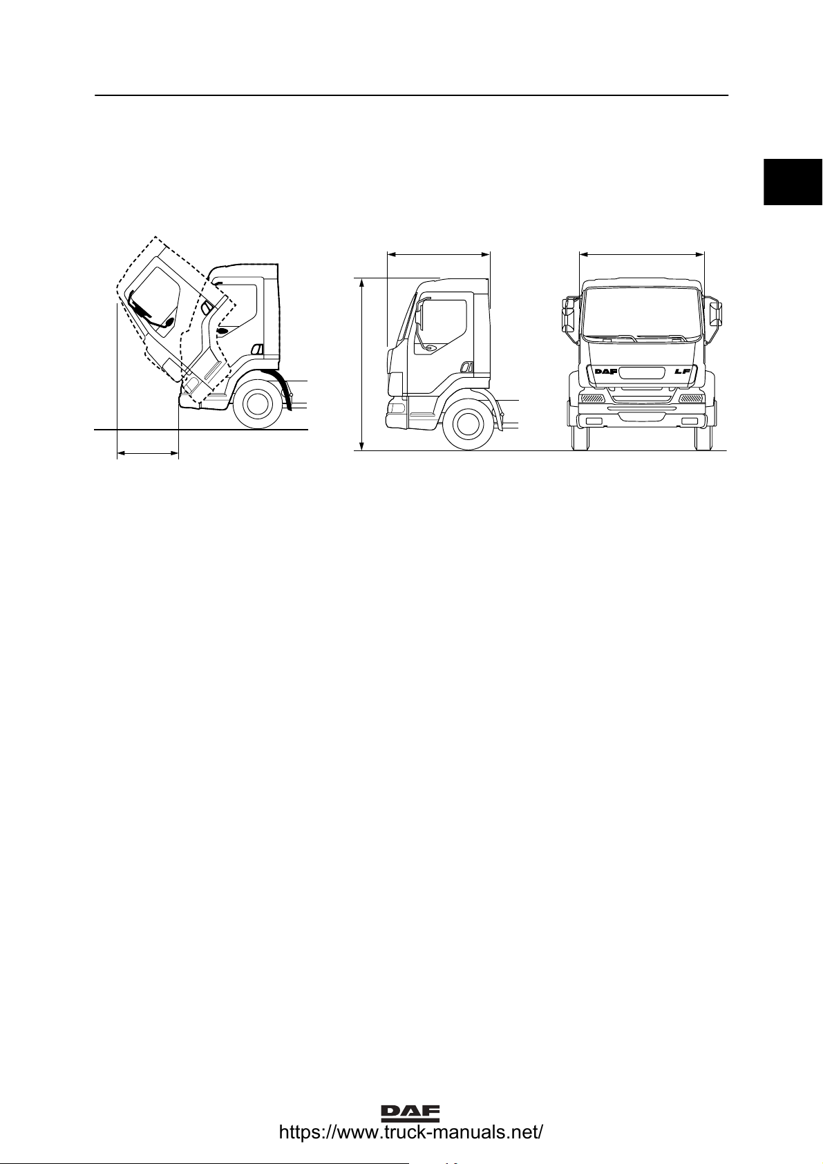
Main dimensions and weights
L
B
H
K
K1 01 170
Cab dimensions in mm: Day cab Sleeper Cab
length (L) 1600 mm 2000 mm
width (B) 2130 mm 2130 mm
max. height (H) 2900 mm
tilting (K) 1105 mm
(1)
(2)
2900 mm
1105 mm
(1)
(2)
0
K1 01 192
Cab weights:
Day cab 595 kg
Sleeper cab 750 kg
Notes:
(1)
Height (H) dependent on version and tyre
size
(2)
Dimension K measured from the front of
the bumper.
ǹ 0210
1-1
Page 6

0
1TECHNICAL DATA
Internal and external cab components LF45/55 series
Permissible cab weights: max.
Roof console evenly distributed 5 kg
Roof evenly distributed 150 kg
Weight on the bunk 125 kg
Cab side members
Welding on cab side members is NOT
permitted.
When repairing the cab side member, you must
use sheet-metal trimming panels.
These must be fitted by spot welding.
1-2
ǹ 0210
Page 7

1
LF45/55 series Internal and external cab components
Straightening dimensions
TECHNICAL DATA
Door opening dimensions
A - D 1283 mm
C - F 887 mm
B - E 1591 mm
E
A
F
B
C
D
K1 01 209
0
ǹ 0210
1-3
Page 8
0
1TECHNICAL DATA
Internal and external cab components LF45/55 series
BC
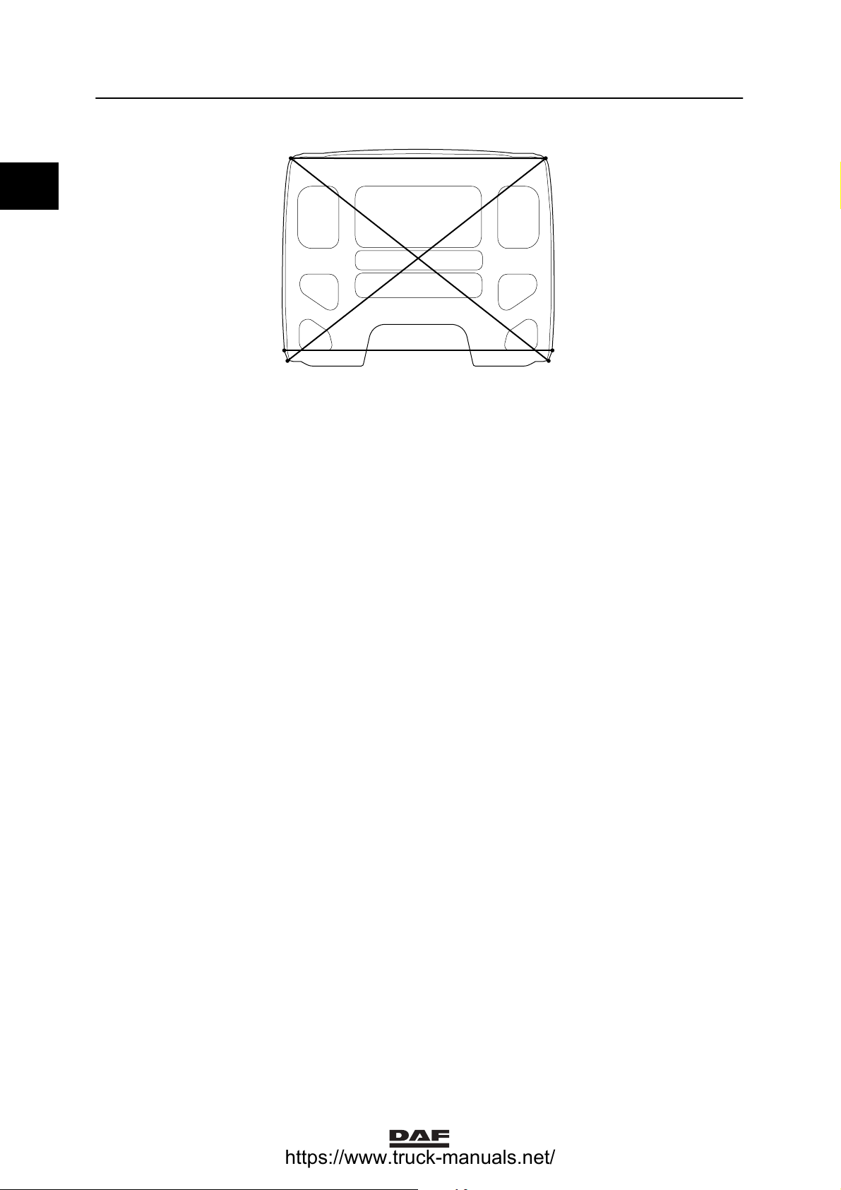
Rear wall dimensions
A - D 2042 mm
B - C 1926 mm
B - E 2435 mm
C - F 2435 mm
A
D
F
E
K1 01 208
1-4
ǹ 0210
Page 9

1
TECHNICAL DATA
LF45/55 series Internal and external cab components
Cab front dimensions
A - B 836 mm
C - D 836 mm
E - F 836 mm
G - I 1973 mm
H - J 1973 mm
Front panel dimensions
N - L 1945 mm
K - M 1945 mm
H
G
BCE
ADF
N K
M
K1 01 210
I
0
J
L
ǹ 0210
1-5
Page 10

0
1TECHNICAL DATA
Internal and external cab components LF45/55 series
Field of vision dimensions
D
1
A
A
2
A
3
A
1
B
1
B
B
B
B
3
5
2
B
4
D
C
C
2
C
3
C
4
C
1
K100237
Mirror size 1 size 2 size 3 size 4 size 5
Pavement mirror [A] 1m 1m 1.25 m
Wide-angle mirror [B] 2.5 m 15 m 12.5 m 25 m 3m
Main mirror on co-driver’s
30 m 3.5 m 0.75 m 4m
side [C]
Main mirror on driver’s
10 m 2.5 m
side [D]
1-6
ǹ 0210
Page 11
1
TECHNICAL DATA
LF45/55 series Internal and external cab components
Windscreens
Curing times for windscreen adhesive
Product name DAF number Vehicle mobile in
workshop after:
Sikaflex 255 FC 1271129 6 hours 8hours 12 hours
Sika Tack Ultrafast 1241020 2 hours 4hours 6 hours
Sika Tack plus
booster
Notes:
(1)
If a vehicle is equipped with an airbag, the
curing time is 2 hours
A relative humidity of less than 50% delays
curing, as does a temperature lower than 20_C.
Product name DAF number Properties Applications
Sikaflex 255 FC 1271129 Processing time
Sika Tack UF 1241020 Processing time
1357925 1hour 1 hour
Products applied for bonded windscreens
20 min.
10 min.
Cab can be tilted
after:
(1)
Adhesive (cold process) for
bonding windscreens
Adhesive (warm process) for
bonding windscreens
Vehicle usable
after:
2 hours
0
Sika Tack plus
booster
Sika Aktivator 1312362 Cleaning fluid for cleaning the glass
Sika remover
SR 208
1357925 Processing time
10 min.
1241019 Removal of adhesive which has not
Adhesive (cold process) for
bonding windscreens
and the frame.
yet hardened. Do not use on
surfaces to be bonded.
ǹ 0210
1-7
Page 12

1TECHNICAL DATA
Internal and external cab components LF45/55 series
1.2 TIGHTENING TORQUES
0
The tightening torques stated in this paragraph
are different from the standard tightening
torques stated in the overview of the standard
tightening torques. The other threaded
connections which are not stated must therefore
be tightened to the tightening torque stated in
the overview of standard tightening torques.
When attachment bolts and nuts are to be
replaced, it is important - unless stated
otherwise - that these bolts and nuts are of
exactly the same length and property class as
the removed ones.
Steering wheel
Steering wheel attachment bolt 50 ᐔ 5Nm
Universal joint
Universal joint attachment bolt 56 ᐔ 5.6 Nm
Airbag
Airbag module attachment bolt 5 ᐔ 1Nm
Contact unit attachment bolt 1.2 Nm
Electronic unit 10 ᐔ 2Nm
Note:
(1)
Always replace the attachment bolt and
nut.
(1)
1-8
ǹ 0210
Page 13

1
TECHNICAL DATA
LF45/55 series Cab suspension
2. CAB SUSPENSION
2.1 GENERAL
The day cab can be fitted with rubber spring
elements at the front. The version with rubber
spring elements at the front does not have a
stabiliser.
The coil spring elements are fitted with shock
absorbers.
The length of the spring elements and the cab
height cannot be adjusted.
On models equipped with coil spring elements at
the front, a difference in cab height can be
corrected to a certain extent using the stabiliser
bar.
At the rear, coil springs are used. The length of
the spring elements varies depending on
whether a day cab or a sleeper cab is involved.
Cab support, general
The distance between the cab
supports (A) measured from the
left side of the left support to the
left side of the right support is:
1000 mm
0
9
11
15
10
12
16
13
14
K1 00 575
ǹ 0210
2-1
Page 14
1TECHNICAL DATA
Cab suspension LF45/55 series
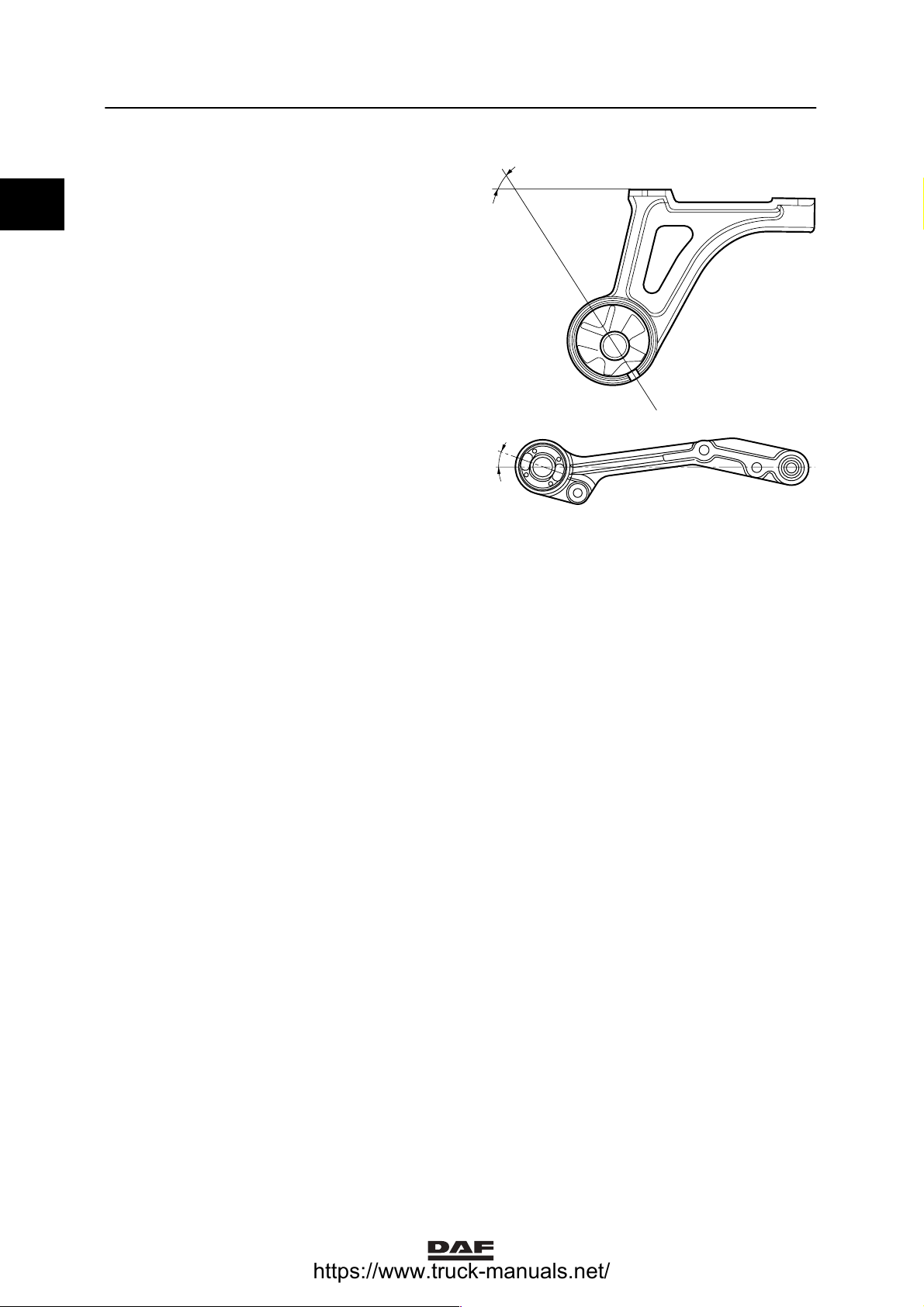
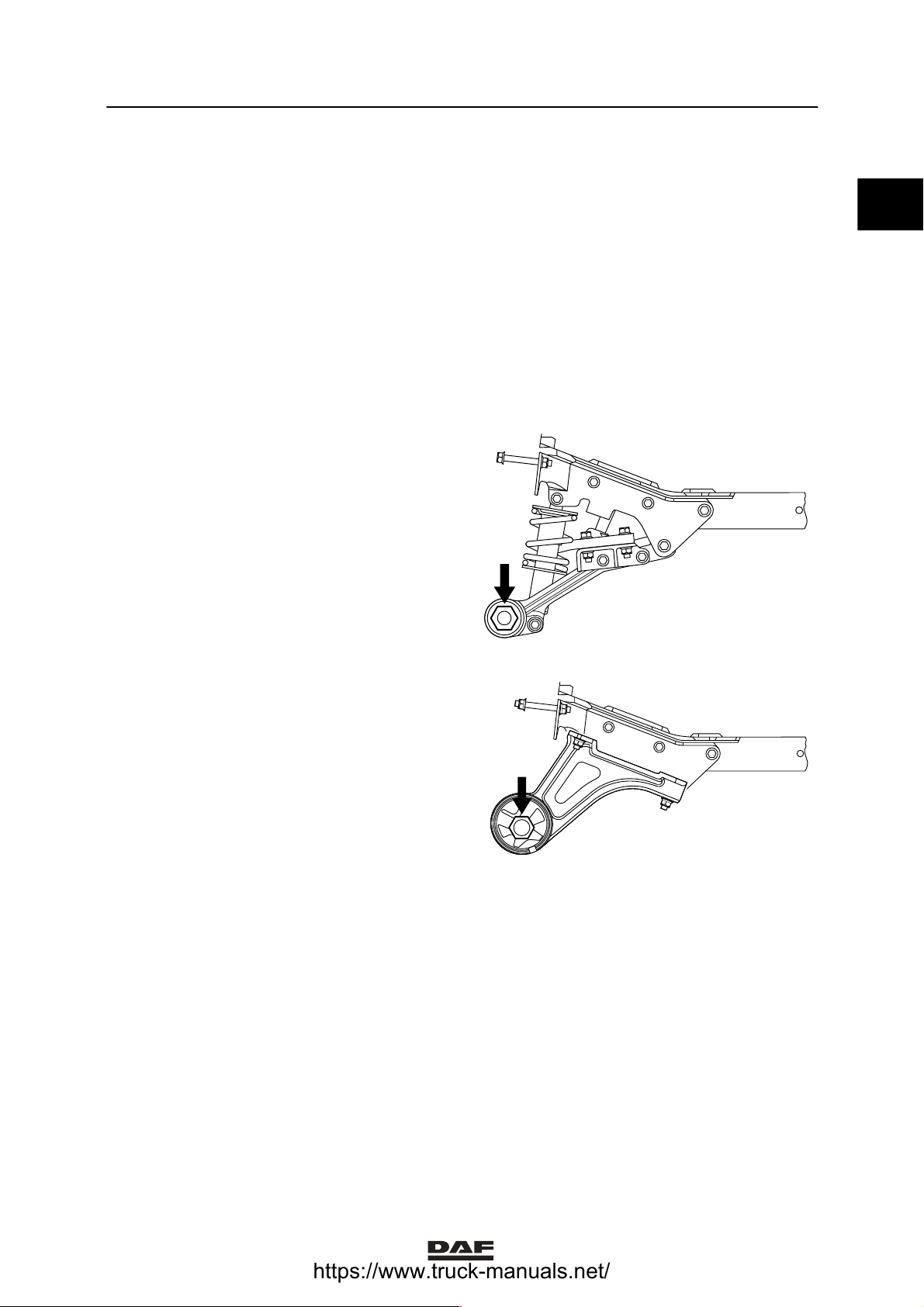
0
Cab support with silentblock
Silent block mounting angle (A) 67_ -71_
Cab support with coil spring suspension
Silent block mounting angle (A) 18_ -22_
A
K1 01 475
A
K1 01 442
2-2
ǹ 0210
Page 15
1
TECHNICAL DATA
LF45/55 series Cab suspension
2.2 TIGHTENING TORQUES
The tightening torques stated in this paragraph
are different from the standard tightening
torques stated in the overview of the standard
tightening torques. The other threaded
connections which are not stated must therefore
be tightened to the tightening torque stated in
the overview of standard tightening torques.
When attachment bolts and nuts are to be
replaced, it is important - unless stated
otherwise - that these bolts and nuts are of
exactly the same length and property class as
the removed ones.
Attachment bolts for cab suspension
using coil springs
Cab suspension
attachment bolt
250 Nm + 150_
angular
displacement
0
K1 01 573
Attachment bolts for cab suspension
using rubber spring elements
Cab suspension
attachment bolt
250 Nm + 150_
angular
displacement
1
K1 01 574
ǹ 0210
2-3
Page 16

0
1TECHNICAL DATA
Cab suspension LF45/55 series
2-4
ǹ 0210
Page 17

1
LF45/55 series Cab tilting gear
TECHNICAL DATA
3. CAB TILTING GEAR
3.1 GENERAL
Lifting cylinder
Nominal pressure 250 bar
Cab tilting pump
Nominal pressure 250 bar
Pressure limiting valve 350 + 30 bar
3.2 FILLING CAPACITIES
Cab tilting pump
Effective oil capacity of the cab-tilting pump. 200 cm
3
0
ǹ 0210
3-1
Page 18

0
1TECHNICAL DATA
Cab tilting gear LF45/55 series
3-2
ǹ 0210
Page 19

1
TECHNICAL DATA
LF45/55 series Seats
4. SEATS
4.1 GENERAL
Height control valve
Adjusting dimension X for height control valve 1 - 2 mm
4.2 TIGHTENING TORQUES
The tightening torques stated in this paragraph
are different from the standard tightening
torques stated in the overview of the standard
tightening torques. The other threaded
connections which are not stated must therefore
be tightened to the tightening torque stated in
the overview of standard tightening torques.
When attachment bolts and nuts are to be
replaced, it is important - unless stated
otherwise - that these bolts and nuts are of
exactly the same length and property class as
the removed ones
M8 attachment bolt 22 Nm
M10 attachment bolt 22 Nm
Attachment bolt 7/16″ UNF-2B 37 Nm
.
0
ǹ 0210
4-1
Page 20

0
1TECHNICAL DATA
Seats LF45/55 series
4-2
ǹ 0210
Page 21

1
TECHNICAL DATA
LF45/55 series Accessories
5. ACCESSORIES
5.1 GENERAL
Roof spoiler
Adjusting range of roof spoiler, aerodynamic
and adjustable
Note:
The roof spoiler height can be adjusted using
adjusting mechanism (B).
Thesizeisthedistancemeasuredbetweenthe
highest roof spoiler edge (P) and the cab roof
plate local to the vehicle centreline.
Application compounds for rear air foils and
roof spoilers
Product name
Sikaflex 252
(white)
DAF number Properties Applications
1286578 Working time within
15 min.
Curing time 2 days
0
350 - 850 mm
P
B
K1 01 355
Kit for fender and roof spoiler
attachment
ǹ 0210
5-1
Page 22

1TECHNICAL DATA
Accessories LF45/55 series
5.2 TIGHTENING TORQUES
0
The tightening torques stated in this paragraph
are different from the standard tightening
torques stated in the overview of the standard
tightening torques. The other threaded
connections which are not stated must therefore
be tightened to the tightening torque stated in
the overview of standard tightening torques.
When attachment bolts and nuts are to be
replaced, it is important - unless stated
otherwise - that these bolts and nuts are of
exactly the same length and property class as
the removed ones.
Roof spoiler
Attachment nuts 13 Nm
Rear air foil
Attachment nuts 13 Nm
Sun visor
Bracket attachment bolts 13 Nm
Bolt for attaching the sun visor to the bracket 10 Nm
5-2
ǹ 0210
Page 23

1
LF45/55 series Contents
DIAGNOSTICS
CONTENTS
Page Date
1. CAB SUSPENSION 1-1 0210.................................................... ......
1.1 Fault-finding table, cab tilting mechanism 1-1 0210............................ ......
1
ǹ 0210
1
Page 24

1
1DIAGNOSTICS
Contents LF45/55 series
2
ǹ 0210
Page 25

1
DIAGNOSTICS
LF45/55 series Cab suspension
1. CAB SUSPENSION
1.1 FAULT-FINDING TABLE, CAB TILTING MECHANISM
COMPLAINT: TILTING CYLINDER FAILS TO RESPOND
Possible cause Remedy
Damaged or broken pipe. Replace pipe or connection.
Pump reservoir empty. Top up reservoir and check for leakage.
Worn or damaged cylinder seal. Replace the cylinder or seal.
COMPLAINT: PUMP ROD REBOUNDS
Possible cause Remedy
Leaking non-return valve. Disassemble the two-way valve of the pump.
Clean and degrease the valve components.
Replace all seals and assemble the two-way
valve.
COMPLAINT: PUMP ONL Y FUNCTIONS IN THE LAST P ART OF THE STROKE
Possible cause Remedy
Low oil level in oil reservoir. Topupoilreservoir.
Leaking inlet valve (ball). Remove the two-way valve and check the inlet
valve. Clean or replace it.
Polluted inlet strainer. Clean the reservoir and strainer.
1
COMPLAINT: PUMP FAILS TO BUILD UP PRESSURE
Possible cause Remedy
Reservoir level too low. Topupthereservoir.
Leaking inlet valve (ball). Remove the two-way valve and check the inlet
valve. Clean or replace it.
Worn or damaged O-rings on the two-way
valve.
Pressure-relief valve incorrectly set. Check the pressure relief valve and adjust, if
Remove the two-way valve and replace all seals
and O-rings.
necessary.
ǹ 0210
1-1
Page 26

1
1DIAGNOSTICS
Cab suspension LF45/55 series
COMPLAINT: CAB LOCK CANNOT BE OPENED
Possible cause Remedy
Damaged or broken pipe. Replace pipe or connection.
Jammed piston in locking mechanism. Repair or replace the locking mechanism.
COMPLAINT: CAB CANNOT BE TILTED
Possible cause Remedy
Jammed piston in cab locking mechanism. Repair or replace the locking mechanism.
Pump fails to build up pressure. Check the operation of the pump.
1-2
ǹ 0210
Page 27

1
INTERNAL CAB COMPONENTS
LF45/55 series Contents
CONTENTS
Page Date
1. SAFETY INSTRUCTIONS 1-1 0210............................................... ......
2. GENERAL 2-1 0210............................................................ ......
2.1 Overview drawing, interior cab components 2-1 0210.......................... ......
2.2 System description, steering column 2-2 0210................................ ......
3. INSPECTION AND ADJUSTMENT 3-1 0210....................................... ......
3.1 Inspection, steering column setting valve 3-1 0210............................. ......
4. REMOVAL AND INSTALLATION 4-1 0210........................................ ......
4.1 Removal and installation, switches 4-1 0210.................................. ......
4.2 Removal and installation, dashboard panels 4-2 0210.......................... ......
4.3 Removal and installation of complete dashboard 4-9 0210...................... ......
4.4 Removal and installation, pneumatic switch/valve of
steering column adjustment unit 4-15 0210.................................... .....
4.5 Removal and installation, steering column 4-17 0210............................ .....
4.6 Removal and installation, steering wheel 4-22 0210............................. .....
4.7 Removal and installation, door panel 4-26 0210................................ .....
4.8 Removal and installation, manually operated window mechanism 4-28 0210........ .....
4.9 Removal and installation, electrically operated window mechanism 4-29 0210...... .....
4.10 Removal and installation, roof console 4-30 0210............................... .....
4.11 Removal and installation, interior lighting 4-31 0210............................. .....
4.12 Removal and installation, ignition lock 4-31 0210............................... .....
4.13 Removal and installation, complete door lock mechanism 4-32 0210.............. .....
4.14 Removal and installation, door lock cylinder 4-34 0210.......................... .....
4.15 Removal and installation, engine brake switch 4-34 0210........................ .....
4.16 Removal and installation, rear wall lining 4-35 0210............................. .....
4.17 Removal and installation, roof lining 4-36 0210................................. .....
4.18 Removal and installation, side wall lining 4-37 0210............................. .....
4.19 Removal and installation, storage trays (sleeper cab) 4-37 0210.................. .....
2
ǹ 0210
1
Page 28

2
1INTERNAL CAB COMPONENTS
Contents LF45/55 series
2
ǹ 0210
Page 29

1
INTERNAL CAB COMPONENTS
LF45/55 series Safety instructions
1. SAFETY INSTRUCTIONS
General
The cab is equipped with a hydraulic tilting
mechanism. The pump is located on co-driver’s
side at the rear of the cab. The cab locks are
opened hydraulically during pumping.
Before tilting the cab, make sure that the doors
are closed, that there are no loose items in the
cab and that the gear lever is in neutral. Tilt the
cab fully forward if work must be carried out
underneath the cab.
You can stop the cab tilting forward
atanytimebyturningthetaptothe
reverse tilting position.
When working on a tilted cab (for
example when welding,
spray-painting or applying bitumen
coatings), be sure to cover the
piston rod of the lifting cylinder.
Welding spatter and paint on the
piston rod will inevitably cause
damage to the oil seal.
2
Inspection after a collision
Before tilting the cab after a collision, check the
cab rests, the cab hinges and the attachment of
the lifting cylinder to the chassis member and
cab for cracks.
If the vehicle has been involved in a
collision, the cab must under no
circumstances be tilted without due
precautions. The end stop in the
lifting cylinder may be damaged,
which might cause the cab to shoot
past its end stop.
If possible, suspend the cab in slings and put a
stand in front of the cab. Make sure that there is
no one in front of the cab while it is being tilted.
ǹ 0210
1-1
Page 30

2
1INTERNAL CAB COMPONENTS
Safety instructions LF45/55 series
Replacing the lifting cylinder
After a collision, always check the lifting
cylinder for internal damage.
Replace the lifting cylinder if damaged or if you
are in doubt as to the its condition.
Always replace the cylinder if one of the
following points has occurred during a collision:
A. the cab has been pulled out of the cab
locks,
B. the cab locks have been deformed or
damaged,
C. the rear cab springs have been deformed
or damaged.
Airbag and seat belt tensioner safety
instructions
- Never disconnect an electrical connection in
the airbag or seat belt tensioner circuits
with the ignition switched on.
- All work on pyrotechnic systems (systems
with airbag(s) and/or seat belt tensioner(s))
may only be carried out by employees of
approved DAF dealers or workshops who
are sufficiently trained on these systems.
- The use of pyrotechnic systems (systems
with airbag(s) and/or seat belt tensioner(s))
is subject to various national laws. The legal
stipulations must be observed.
1-2
ǹ 0210
Page 31

1
INTERNAL CAB COMPONENTS
LF45/55 series Safety instructions
- Vehicles equipped with a pyrotechnic
system (system with airbag(s) and/or seat
belt tensioner(s)) can be identified by a
sticker with an airbag symbol on the
windscreen and/or with the word AIRBAG
on the airbag unit on the steering wheel.
- If the vehicle is equipped with an airbag and
seat belt tensioner system while there is no
airbag symbol on the windscreen, this
symbol will have to be applied as yet.
K101290
- It is not permitted to install accessories on
airbag and seat belt tensioner parts or in
their operating zones afterwards. The
operating zone covers an area the size of a
ball with a diameter of 80 cm. Only
accessories approved by DAF for vehicles
with an airbag and/or seat belt tensioner
may be installed, in the place indicated by
DAF and in the manner outlined by DAF.
2
- Using equipment or objects that generate
strong electromagnetic fields in the vicinity
of parts of the airbag/seat belt tensioner
system can lead to unwanted activation of
the airbag and/or seat belt tensioner or can
make proper operation of the system
impossible. The use of such equipment or
objects in the vicinity of parts of the
airbag/seat belt tensioner system is
therefore not recommended.
G0 00 235
ǹ 0210
1-3
Page 32

2
1INTERNAL CAB COMPONENTS
Safety instructions LF45/55 series
- It is not allowed to leave pyrotechnic units
(airbags and/or seat belt tensioners)
unattended. If repairs to a vehicle continue
for a long time and pyrotechnic units
(airbags and/or seat belt tensioners) are
involved in the repair, the pyrotechnic units
must be stored safely (under lock and key).
This means that the storage location must
meet local requirements relating to
pyrotechnic materials. The pyrotechnic
units may not be stored together with
different hazardous substances and the
location must have the relevant hazard
warning symbols and fire protection
facilities.
- Before any work is carried out on a
pyrotechnic part (airbag and/or seat belt
tensioner):
a. switch off the ignition.
b. the negative battery terminal clamp
must be separated carefully.
c. wait at least 5 minutes.
- If pyrotechnic units have been activated in a
crash, the electronic unit and the contact
unit must be replaced in addition to the
pyrotechnic units. The cable harness
assembly and connectors must be
inspected visually. If damage or overload is
established, the cable harness assembly
must be replaced.
1-4
ǹ 0210
Page 33

1
INTERNAL CAB COMPONENTS
LF45/55 series General
2. GENERAL
2.1 OVERVIEW DRAWING, INTERIOR CAB COMPONENTS
1 2 3 4 6 7 8 9 10
Legend
1. Left-side ventilation grille
2. Instrument panel
3. Garnish moulding
4. Radio panel
5. Frame rim cover panel
6. Upper dashboard panel on driver’s side
7. Central console control panel
8. Upper side of cover panel
9. Upper side of cover
10. Right-side ventilation grille
1 1. Right-side dashboard panel
12. Lid on central box
13. Lower dashboard panel on co-driver ’s side
14. Ashtray
15. Engine tunnel dashboard panel
16. Lower dashboard panel on driver’s side
17. Steering column dashboard panel
5
11
2
12
13
151617
14
K1 01 438
ǹ 0210
2-1
Page 34

2
1INTERNAL CAB COMPONENTS
General LF45/55 series
2.2 SYSTEM DESCRIPTION, STEERING COLUMN
The tilting angle of the steering column can be
adjusted manually or pneumatically.
A spring-loaded clamping mechanism fixes the
steering column in position.
The pneumatically adjusted steering column is
unlocked using the air cylinder behind the
steering column.
The operating valve (switch) is situated behind
the driver’s seat. This valve can be operated by
the heel.
K1 01 425
K1 01 202
2-2
ǹ 0210
Page 35

1
LF45/55 series Inspection and adjustment
INTERNAL CAB COMPONENTS
3. INSPECTION AND ADJUSTMENT
3.1 INSPECTION, STEERING COLUMN SETTING VALVE
1. Check whether the angle of the steering
column can be adjusted, once the switch is
pressed in with the heel.
2. Check that the adjustment mechanism is
securely locked again when the switch is
released.
3. If this is not the case, check that no air pipe
is trapped. If not, replace the valve (switch).
K1 01 202
2
ǹ 0210
3-1
Page 36

2
1INTERNAL CAB COMPONENTS
Inspection and adjustment LF45/55 series
3-2
ǹ 0210
Page 37

1
LF45/55 series Removal and installation
INTERNAL CAB COMPONENTS
4. REMOVAL AND INSTALLATION
4.1 REMOVAL AND INSTALLATION, SWITCHES
Removing switches
1. Insert a feeler gauge of approx. 1 mm
straight between the switch and the panel at
the side of the finger-sized depression (A),
until it touches the inside of the panel.
B
2. Remove the switch from its locked position
by carefully moving the feeler gauge in the
direction of the arrow (B).
3. Carefully remove the switch from the panel.
In doing so, ensure that the connector lock
does not catch behind the panel, causing
the connector to fall behind the panel.
4. If necessary, remove the switch from the
connector.
Installing switches
1. Fit the connector.
2. Insert the switch into the opening in the
panel and press until you can feel it lock.
A
A
2
K1 01 186
B
K100389
ǹ 0210
4-1
Page 38

2
INTERNAL CAB COMPONENTS
1
Removal and installation LF45/55 series
4.2 REMOVAL AND INSTALLATION, DASHBOARD PANELS
Note:
Dashboard panel removal and installation is
listed in the correct sequence. To allow each
following panel to be removed, the earlier
specified panels must be removed first.
Removing steering column dashboard panel
1. If necessary, remove the floor mat.
2. Using the steering column setting, move the
steering wheel to its highest possible
position.
3. Remove the attachment bolts (1) and panel
plug (2) and subsequently the steering
column dashboard panel.
21
K1 01 427
Removing the lower dashboard panel on
co-driver’s side
1. Remove the attachment bolts from the
lower dashboard panel on co-driver’s side.
Remove the lower dashboard panel on
co-driver’s side
Removing the engine tunnel dashboard
panel
1. Remove the attachment bolts (1) and the
panel plugs (2). Remove the engine tunnel
cover panel.
2. Loosen the 12V power supply connector at
the rear.
K1 01 428
4-2
21
K1 01 429
ǹ 0210
Page 39

1
INTERNAL CAB COMPONENTS
LF45/55 series Removal and installation
Removing the instrument panel
1. Remove the attachment bolts (1) of the
garnish moulding (2) around the instrument
panel (3).
2. Carefully pull the mounting clips (see
arrows) holding down the garnish moulding
(2) from the dashboard panel.
3. Remove the attachment bolts from the
instrument panel (3).
4. Remove the instrument panel (3).
5. Remove the connector from the instrument
panel (3).
Removing the lower dashboard panel on
driver’s side
1. Remove the attachment bolts (1). Remove
the dashboard panel.
2. Loosen the headlamp height adjustment
connector at the rear.
3. Remove the attachment bolts from the
connector block at the rear of the
dashboard panel.
3
1
1
2
2
K1 01 430
1
K1 01 431
4. Remove the connector block.
Removing the window frame cover panel
1. Remove the attachment bolts (1) from the
window frame.
2. Take the cover panel out of the window
frame.
1
K1 01 432
ǹ 0210
4-3
Page 40

2
INTERNAL CAB COMPONENTS
1
Removal and installation LF45/55 series
Removing the upper cover
1. Remove the attachment bolts at the bottom
of the cover.
2. Remove the cover from the upper cover
panel by tilting it upwards.
K1 01 433
Removing the central console control panel
1. Remove the switches (3) from the control
panel in the central console (5).
1
5
2. Remove the ashtray (2) from the control
panel in the central console (5).
3. Remove the attachment bolts (1) from
control panel in the central console (5).
4. Remove the control panel from the central
console (5).
3
5. Disconnect the connector of the cigarette
lighter (4).
Removing the right-side dashboard panel
1. Remove the dashboard panel attachment
bolts.
2. Remove the connector from the stepwell
lighting door switch
2
4
1
K1 01 434
K1 01 435
4-4
ǹ 0210
Page 41

1
INTERNAL CAB COMPONENTS
LF45/55 series Removal and installation
Removing the upper dashboard panel on
driver’s side
1. Remove the attachment bolts (1) from the
radio panel (2).
2. Remove the attachment bolts (3) from the
dashboard panel.
3. Cut the cable binders that are used to
attach the wiring harnesses to the
dashboard panel.
4. Remove the dashboard panel. Unhook the
radio panel (2) from the dashboard panel.
5. Disconnect the connector of the light switch
(4) and the stepwell lighting door switch.
Installing the upper dashboard panel on
driver’s side
1. Fit the connector of the light switch (4) and
the stepwell lighting door switch.
2. Fit the dashboard panel. Hook the radio
panel (2) to the dashboard panel.
3. Fix the removed cable harnesses to the
dashboard panel using cable binders.
3
1
2
42
K1 01 436
3
1
4. Fit the dashboard panel attachment
bolts (3).
5. Fit the attachment bolts (1) of the radio
panel (2) to the dashboard panel.
Installing the right-side dashboard panel
1. Fit the connector of the stepwell lighting
door switch to the right-side dashboard
panel
2. Fit the right-side dashboard panel using the
attachment bolts.
42
K1 01 436
K1 01 435
ǹ 0210
4-5
Page 42

INTERNAL CAB COMPONENTS
1
Removal and installation LF45/55 series
2
Installing the central console control panel
1. Re-fit the connector of the cigarette lighter
(4) to the rear of the control panel of the
central console (5).
2. Fit the control panel of the central console
(5) to the dashboard.
3. Hook up the switches (3) from the control
panel in the central console (5) to the
connectors. Re-fit the switches (3) to the
control panel in the central console (5).
4. Secure the control panel in the central
console (5) using the attachment bolts (1).
5. Fit the ashtray (2) into the control panel in
the central console (5).
Fitting the upper cover
1. Hook the cover into the cover panel. Fit the
cover into the cover panel using the
attachment bolts.
1
5
3
2
4
1
K1 01 434
Fitting the cover panel into the window frame
1. Fit the cover panel into the window frame
using the attachment bolts (1).
K1 01 433
1
K1 01 432
4-6
ǹ 0210
Page 43

1
INTERNAL CAB COMPONENTS
LF45/55 series Removal and installation
Fitting the lower dashboard panel on driver’s
side
1. Fit the connector block to the rear of the
dashboard panel using the attachment
bolts.
2. Fit the connector of the headlamp height
adjustment unit to the dashboard panel.
3. Fit the dashboard panel using the
attachment bolts (1).
Installing the instrument panel
1. Fit the connector of the instrument
panel (3).
2. Fit the instrument panel (3) to the
dashboard panel using the attachment
bolts.
3. Push the garnish moulding (2) back onto
the dashboard panel using the mounting
clips. Fix the garnish moulding (2) onto the
dashboard panel using the attachment
bolts (1)
Fitting the engine tunnel dashboard panel
1. Remove the attachment bolts (1) and the
panel plugs (2). Remove the engine tunnel
cover panel.
2. Fit the connector of the 12V power supply to
the rear of the engine tunnel dashboard
panel.
1
K1 01 431
2
3
1
1
2
K1 01 430
21
K1 01 429
ǹ 0210
4-7
Page 44

2
INTERNAL CAB COMPONENTS
1
Removal and installation LF45/55 series
Fitting the lower dashboard panel on
co-driver’s side
1. Fit the lower dashboard panel on co-driver’s
using the attachment bolts.
K1 01 428
Installing the steering column dashboard
panel
1. Fit the steering column dashboard panel
using the attachment bolts (1) and panel
plug (2).
21
K1 01 427
4-8
ǹ 0210
Page 45

1
INTERNAL CAB COMPONENTS
LF45/55 series Removal and installation
4.3 REMOVAL AND INSTALLATION OF COMPLETE DASHBOARD
7
2
456
Removing the dashboard
1. Disconnect the earth lead from the battery
terminal.
2. Remove the attachment bolts and the panel
plug (6). Remove the steering column cover
panel.
3. Remove the attachment bolts (1), (2) and
(3) and remove the cover panel on
co-driver’s side.
4. Remove the attachment bolts (4) and the
panel plugs (5). Remove the engine tunnel
cover panel. Remove the connector from
the 12V power supply.
5. Remove the attachment bolts (7) and
remove the upper cover panel.
6. Open the grille.
123
K1 01 437
ǹ 0210
4-9
Page 46

INTERNAL CAB COMPONENTS
1
Removal and installation LF45/55 series
2
7. Remove the attachment bolt (1).
8. Remove the protective cover by pressing
the retainer (2) aside.
9. Detach the connectors (1) from the
connecting block.
10. Press the connecting block retainer (2)
inside and push the complete connecting
block inside.
2
1
K1 00 988
2
1
11. Remove the cover plate (2) by releasing the
retainer (1).
1
2
11
K100989
K1 00 994
4-10
ǹ 0210
Page 47

1
INTERNAL CAB COMPONENTS
LF45/55 series Removal and installation
12. Remove the connectors (2).
13. Push the retainers (1) aside and the
connector holder plate inside.
14. Remove the attachment bolts (1) from the
filter casing and remove the filter casing (2).
2
1
2
K1 00 990
1
1
15. Remove the attachment bolts (1).
16. Remove the heater hoses (2) and seal the
heater tubes.
17. Remove the connectors to the left and right
of the steering column.
1
2
K1 01 194
2
1
K1 01 175
ǹ 0210
4-11
Page 48

INTERNAL CAB COMPONENTS
1
Removal and installation LF45/55 series
18. Remove the connectors (2) and the earth
connections (3).
19. Remove the attachment bolts on the
underside of the dashboard, left and right.
2
20. Remove the attachment bolts (4) and (1).
21. Pull the cover plate in the A-pillar out of the
retainer, remove the grip attachment bolt
and remove the grip (5).
22. Remove the floor mats. Remove the
diagnostic and ECAS connectors by taking
the wiring apart and then removing the
attachment bolts. Remove the connectors
from the bracket.
23. Remove the floor plate above the wiring.
24. Remove the seat wiring.
25. Remove the attachment bolts from the
window frame.
26. Remove the attachment bolts on the
underside and remove the complete
dashboard.
Fitting the dashboard
1. Fit the dashboard and secure it in the
window frame using a few attachment bolts.
2. Fit the seat wiring.
1
2
5
3
4
K1 00 986
3. Install the floor plate above the wiring.
4. Fit the ECAS and diagnostic connectors to
the bracket.
5. Fit the grip and the cover panel in the
A-pillar.
6. Fit the connectors in the central box.
7. Remove the seals from the coolant hoses
and attach the hoses.
8. Fit the connectors to the left and right of the
steering column.
4-12
ǹ 0210
Page 49

1
INTERNAL CAB COMPONENTS
LF45/55 series Removal and installation
9. Insert the attachment bolts (1).
10. Fit the heater hoses (2).
11. Fit the filter casing (2). Secure the filter
casing using the attachment bolts (1).
2
1
2
K1 01 175
1
1
1
2
K1 01 194
12. Fit the plate for the connectors via the
inside and press it into the retainers (2).
13. Fit the connectors (1).
14. Fit the cover plate.
2
1
1
K1 00 994
ǹ 0210
4-13
Page 50

INTERNAL CAB COMPONENTS
1
Removal and installation LF45/55 series
2
15. Fit the connecting block via the inside and
press it firmly into the retainers (2).
16. Fit the connectors (1) to the connecting
block. Pay attention to the markings on the
components.
17. Fit the protective cover to the cab lead
through and secure it using the attachment
bolt (1).
2
1
1
2
K1 00 994
1
18. Close the grille.
19. Fit the attachment bolts under the
dashboard to the left and right.
20. Secure the attachment bolts in the window
frame.
21. Fit the dashboard panels on co-driver’s
side.
22. Fit the steering column dashboard panels.
23. Fit the connector of the 12V power supply to
the engine tunnel cover panel.
24. Fit the cover panel to the engine tunnel.
25. Fit the earth lead to the battery terminal.
K1 00 988
4-14
ǹ 0210
Page 51

1
INTERNAL CAB COMPONENTS
LF45/55 series Removal and installation
4.4 REMOVAL AND INSTALLATION, PNEUMATIC SWITCH/VALVE OF
STEERING COLUMN ADJUSTMENT UNIT
Removing the pneumatic switch/valve of the
steering column adjustment unit
1. Lay the floor mat aside.
2. Remove the attachment bolts (1) from the
switch/valve.
3. Remove the bracket holding the
switch/valve. Disconnect the air pipes (2)
and remove the switch/valve.
1
2
K1 01 120
ǹ 0210
2
K1 01 121
4-15
Page 52

2
INTERNAL CAB COMPONENTS
1
Removal and installation LF45/55 series
Fitting the pneumatic switch/valve
1. Fit the air pipes (2) to the switch/valve.
2
K1 01 121
2. Fit the switch/valve and secure them using
the attachment bolts (1).
3. Check the operation of the switch/valve, see
chapter ”Inspection and Adjustment”.
4. Reposition the floor mat.
1
K1 01 120
4-16
ǹ 0210
Page 53

1
INTERNAL CAB COMPONENTS
LF45/55 series Removal and installation
4.5 REMOVAL AND INSTALLATION, STEERING COLUMN
Note:
A steering wheel with an airbag can be
recognised by the inscription ”airbag” on the
cover plate and the ”Airbag” sticker on the
windscreen.
Steering wheel model without airbag
Removing the steering column without
airbag steering wheel
1. Place the steering box in the central
position using the marks.
2. Remove the steering column panel.
3. Depending on the work to be carried out,
remove the floor dust cover or the cover
panels beneath the steering wheel.
4. If applicable, remove the steering column
adjustment air pipe.
2
S7 00 623
5. Remove the connectors from the steering
column.
6. Remove the attachment bolt of one
universal joint of the steering shaft
(depending on the operations to be
performed; either the universal joint beneath
the steering wheel or the universal joint on
the steering box). Before loosening, mark
the position of the universal joint versus the
steering shaft.
7. Remove the attachment bolts. One of the
attachment bolts is a security bolt. Remove
this using a drift.
8. Remove the steering column.
ǹ 0210
4-17
Page 54

2
INTERNAL CAB COMPONENTS
1
Removal and installation LF45/55 series
Installing the steering column without airbag
steering wheel
1. Check whether the steering box is still in the
central position, using the markings.
S7 00 623
2. Fit the steering column to the steering shaft
and make sure that the marks between the
universal joint and steering shaft align.
Fit a new attachment bolt with nut in the
universal joint.
Tighten the attachment bolt to the specified
torque, see main group ”Technical data”.
3. Place the steering column by tightening the
top attachment bolts by hand.
4. Attach the air pipes to the connection block
behind the dashboard. Check to see that
the air pipes are not in contact with any
moving parts.
5. Fit the steering column connectors.
6. Fit the lower attachment bolts and lock the
steering column.
7. Fit the steering column panel and secure it
with the attachment bolts and panel clips.
4-18
ǹ 0210
Page 55

1
INTERNAL CAB COMPONENTS
LF45/55 series Removal and installation
Steering wheel model with airbag
Observe the warnings and safety
instructions applicable to working
on an airbag system.
Removing the steering column with airbag
steering wheel
1. Remove the airbag module.
2. Place the steering box in the central
position using the marks.
3. Remove the panel under the tachograph.
There must at least be 5 minutes
waiting time between disconnecting
the battery leads and loosening the
airbag connector. Non-observance
of the 5 minutes waiting time may
result in the airbag being activated
when the connector is removed.
2
S7 00 623
4. Remove the steering column panel.
5. Depending on the work to be carried out,
remove the floor dust cover or the cover
panels under the steering wheel.
6. If applicable, remove the steering column
adjustment air pipe.
7. Remove the connectors from the steering
column.
ǹ 0210
4-19
Page 56

2
INTERNAL CAB COMPONENTS
1
Removal and installation LF45/55 series
8. Remove the attachment bolt of one
universal joint of the steering shaft
(depending on the operations to be
performed; either the universal joint under
the steering wheel or the universal joint on
the steering box). Before loosening, mark
the position of the universal joint versus the
steering shaft.
9. Lock the steering wheel to prevent it from
turning, using, for example, adhesive tape
If the steering wheel is rotated more
than 3 turns to the left or right from
the centre position, the airbag
contact unit will get damaged.
10. Remove the attachment bolts. One of the
attachment bolts is a security bolt. Remove
this using a drift.
11. Remove the steering column.
4-20
ǹ 0210
Page 57

1
INTERNAL CAB COMPONENTS
LF45/55 series Removal and installation
Installing the steering column with airbag
steering wheel
1. Check that the steering box is still in the
central position, using the marks.
S7 00 623
2. Fit the steering column to the steering shaft
and make sure that the marks between the
universal joint and steering shaft align.
Fit a new attachment bolt with nut in the
universal joint.
Tighten the attachment bolt to the specified
torque, see main group ”Technical data”.
2
3. Place the steering column by tightening the
top attachment bolts by hand.
4. Attach the air pipes to the connection block
behind the dashboard. Check to see that
the air pipes are not in contact with any
moving parts.
5. Fit the steering column connectors.
6. Fit the lower attachment bolts and lock the
steering column.
7. Fit the steering column panel and secure it
with the attachment bolts and panel clips.
8. Fit the panel.
9. Fit the airbag module.
ǹ 0210
4-21
Page 58

INTERNAL CAB COMPONENTS
1
Removal and installation LF45/55 series
4.6 REMOVAL AND INSTALLATION, STEERING WHEEL
Note:
A steering wheel with an airbag can be
recognised by the inscription ”Airbag” on the
cover plate and the ”Airbag” sticker on the
windscreen.
Steering wheel without airbag
2
Removing the steering wheel without airbag
1. Check that the steering wheel is not
equipped with an airbag.
2. Place the steering box in the central
position using the marks.
3. Remove the cover plate from the steering
wheel.
4. Remove the steering wheel bolt (2).
5. Make marks (A and B) on the steering
wheel (1) and the steering shaft (3).
S7 00 623
1
2
A
4-22
B
3
K1 01 321
ǹ 0210
Page 59

1
INTERNAL CAB COMPONENTS
LF45/55 series Removal and installation
6. Fit the steering wheel puller
(DAF no. 1451995) on the steering wheel.
7. Make sure the bottom of the spindle (1) is
level with the bottom of the attachment
bolts (2).
8. Turn the spindle (1) approximately 10 mm
into the steering shaft.
9. Turn both attachment bolts (2)
approximately 10 mm into the steering
wheel.
10. Evenly tighten both attachment bolts (2)
alternately until the steering wheel comes
loose.
Fitting the steering wheel without airbag
1. Fit the steering wheel (1) on the steering
shaft (3) so that the markings on the
steering wheel and steering shaft (A and B)
”align”. Ensure that the ridges on the rear of
the steering wheel fall into the recesses.
Check that the steering box is still in the
central position, if a new steering wheel is
fitted.
212
2
K1 01 324
1
2
A
2. Fit the attachment bolt (2). Tighten the
attachment bolt to the specified torque, see
main group “Technical data”.
3. Fit the cover plate on the steering wheel.
B
3
K1 01 321
ǹ 0210
4-23
Page 60

2
INTERNAL CAB COMPONENTS
1
Removal and installation LF45/55 series
Steering wheel with airbag
Observe the warnings and safety
instructions applicable to working
on an airbag system.
Removing the steering wheel with airbag
1. Disconnect the earth leads from the battery.
2. Place the steering box in the central
position using the marks.
3. Remove the covers from the steering
column.
There must at least be 5 minutes
waiting time between disconnecting
the battery leads and loosening the
airbag connector. Non-observance
of the 5 minutes waiting time may
result in the airbag being activated
when the connector is removed.
4. Remove the steering wheel bolt (2).
5. Make marks (A and B) on the steering
wheel (1) and the steering shaft (3).
S7 00 623
12
A
4-24
B
3
K1 01 505
ǹ 0210
Page 61

1
INTERNAL CAB COMPONENTS
LF45/55 series Removal and installation
6. Fit the steering wheel puller
(DAF no. 1451995) on the steering wheel.
7. Make sure the bottom of the spindle (1) is
level with the bottom of the attachment
bolts (2).
8. Turn the spindle (1) approximately 10 mm
into the steering shaft.
9. Turn both attachment bolts (2)
approximately 10 mm into the steering
wheel.
10. Evenly tighten both attachment bolts (2)
alternately until the steering wheel comes
loose.
Fitting the steering wheel with airbag
1. Fit the steering wheel (1) on the steering
shaft (3) so that the markings on the
steering wheel and steering shaft (A and B)
”align”. Ensure that the ridges on the rear of
the steering wheel fall into the recesses.
Check that the steering box is still in the
central position, if a new steering wheel is
fitted.
212
2
K1 01 324
12
A
2. Fit the attachment bolt (2). Tighten the
attachment bolt to the specified torque, see
main group “Technical data”.
3. Fit the airbag module.
4. Fit the steering column covers.
B
3
K1 01 505
ǹ 0210
4-25
Page 62

INTERNAL CAB COMPONENTS
1
Removal and installation LF45/55 series
4.7 REMOVAL AND INSTALLATION, DOOR PANEL
Removing the door panel
1. Loosen the cap from the grip by pushing a
screwdriver into the recesses (1).
2. Remove the cap from the grip.
2
3. Remove the caps (2) at the bottom of the
door.
4. Remove the attachment bolts from the door.
5. Remove the attachment bolts (1) from the
grip.
6. Disconnect the electric window and mirror
connectors at the inside of the grip.
7. Push the grip down as far as it will go.
8. Push the control cable clip (2) out of the
grip.
9. Remove the control cable from the door
knob. Put the grip aside.
1
2
2
K1 01 407
1
1
2
1
10. Pull the door panel out of the mounting clips
in the door, starting at the bottom.
11. Lift the door panel out of the window frame.
K1 01 409
K1 01 408
4-26
ǹ 0210
Page 63

1
INTERNAL CAB COMPONENTS
LF45/55 series Removal and installation
Installing the door panel
1. Fit the door panel into the upper part of the
window frame.
2. Press the door panel all around into the
door using the mounting clips.
3. Secure the lower part of the door panel
using the attachment bolts and fit the caps.
4. Position the grip on the door panel.
5. Fit the nipple of the control cable in the door
catch of the grip (A). Fit the coupler into the
grip (B).
6. Secure the control cable coupler into the
grip (C) using the mounting clip.
2
7. Fit the automatic mirror and window
connectors into the grip.
8. Fix the grip to the door using the attachment
bolts (1).
9. Fit the grip cap.
A
B
1
C
K1 01 441
1
2
1
ǹ 0210
K1 01 409
4-27
Page 64

2
INTERNAL CAB COMPONENTS
1
Removal and installation LF45/55 series
4.8 REMOVAL AND INSTALLATION, MANUALLY OPERATED WINDOW
MECHANISM
Removing the manually operated window
mechanism
1. Remove the door panel.
2. Remove the door screen.
3. Support the door window using a block (1)
and remove the attachment bolts (4).
Remove the window on the underside so
that it is no longer locked in position.
4. Remove the attachment bolts (3) and the
attachment nut (2) from the window
mechanism.
5. Tilt the window mechanism (5) and remove
it through the bottom of the door.
Installing manually operated window
mechanism
1. Fit the window mechanism (5) through the
bottom of the door.
3
4
2
5
3
2. Remove the block (1) and hook up the door
window in the window mechanism. Secure
the door window with the attachment
bolts (4).
3. Secure the window mechanism with the
attachment bolts (3) and nut.
4. Close the door window until nearly shut.
Check that the top edge of the window is
parallel with the window frame.
Loosen the attachment bolts (4), if
necessary.
Move the window to the correct position and
re-tighten the attachment bolts.
5. Fit the door screen.
6. Install the door panel.
1
K1 00 977
4-28
ǹ 0210
Page 65

1
INTERNAL CAB COMPONENTS
LF45/55 series Removal and installation
4.9 REMOVAL AND INSTALLATION, ELECTRICALLY OPERATED WINDOW
MECHANISM
Removing the electrically operated window
mechanism
1. Remove the door panel.
2. Remove the door screen.
3. Lower the window, remove the attachment
bolts (2) and slide the window up. Support
the window with a block (1).
4. Disconnect the connector (4) from the
electric motor.
5. Remove the attachment bolts (2) and nuts
(3) and remove the window mechanism
from the door through the opening.
Installing the electrically operated window
mechanism
1. Fit the window mechanism in the door and
fit the attachment bolts (2) and attachment
nuts (3).
2. Connect the electric motor connector (4).
3. Lower the window and attach the window
mechanism to the door using the
attachment bolts (2).
4. Operate the window switch.
Close the window until nearly shut.
Check that the top edge of the window is
parallel with the window frame.
Loosen the attachment bolts (2), if
necessary.
Move the window to the correct position and
re-tighten the attachment bolts.
45
2
3
3
2
1
K1 00 974
5. Fit the door screen.
6. Install the door panel.
ǹ 0210
4-29
Page 66

2
INTERNAL CAB COMPONENTS
1
Removal and installation LF45/55 series
4.10 REMOVAL AND INSTALLATION, ROOF CONSOLE
Removing the roof console
1. Remove the top lighting attachment bolts
from the outside of the vehicle and put the
lighting aside.
2. Remove the top lighting connector.
3. Remove the wiring covers in the roof
console.
4. Remove the interior lighting connector.
5. Remove the loudspeaker and its connector.
6. Remove the wiring harness from the roof
console.
7. Remove the attachment bolts (2) from the
roof console in the window frame.
8. Remove the covers (1) at the front and
remove the attachments bolts behind these
covers.
9. Remove the roof console.
Installing the roof console
1. Put the roof console in place and position it
using a few attachment bolts.
2. Place the attachment bolts at the front of
the roof console and tighten them.
3. Fit the connectors for the interior lighting,
loudspeaker and top lighting.
4. Fit the attachment bolts (2) in the window
frame.
5. Secure the top lighting with the attachment
bolts.
6. Fit the covers (1).
1
2
K1 01 123
4-30
ǹ 0210
Page 67

1
INTERNAL CAB COMPONENTS
LF45/55 series Removal and installation
4.11 REMOVAL AND INSTALLATION, INTERIOR LIGHTING
Removing the interior ceiling lighting
1. Put a screwdriver between the glass cover
(1) and the holder (2).
2. Remove the glass cover (1).
3. Bend the lock levers (B) inwards.
4. Unplug the connectors and remove the
lamp holder.
Fitting the interior ceiling lighting
1. Bend the lock levers (B) outwards.
2. Hook up the connectors and fit the lamp
holder (2).
3. Fit the glass cover (1).
2
1
2
K1 01 169
B
K1 00 617
4.12 REMOVAL AND INSTALLATION, IGNITION LOCK
Removing the ignition lock
1. Remove the covers around the steering
column under the steering wheel.
2. Disconnect the connectors (behind the
dashboard).
3. Drill off the head of the security bolt, use a
bit with the same diameter as the hole
where the head falls and remove the
ignition lock.
Installing the ignition lock
1. Install the ignition lock.
2. Tighten the security bolts with such a
tightening torque that the heads break off.
3. Fit the covers around the steering column.
K1 01 134
ǹ 0210
4-31
Page 68

2
INTERNAL CAB COMPONENTS
1
Removal and installation LF45/55 series
4.13 REMOVAL AND INSTALLATION, COMPLETE DOOR LOCK MECHANISM
Removing the complete door lock
mechanism
1. Close the window.
2. Remove the door panel.
K1 01 408
3. Gently remove the plastic screen (1) from
the door.
4. Remove the attachment bolts (6) from the
closing mechanism.
5. Remove the attachment bolts (5) from the
door lock mechanism.
6. Remove the plug (4) from the central door
locking mechanism.
7. Remove the clamping strips (3) holding in
place the main wiring harness (2) and the
wiring harness of the central door locking
mechanism.
8. Lay the main wiring harness (2) aside
9. Remove the control rod by loosening the
control rod locking (1) through tilting and
unhooking the control rod from the locking.
10. Unhook the door lock mechanism from the
door and allow it to be lowered together with
the door locking
11. Remove the attachment bolts (3) from the
door lock mechanism.
6
5
1
2
3
4
K1 01 439
1
4-32
3
2
K1 01 124
ǹ 0210
Page 69

1
INTERNAL CAB COMPONENTS
LF45/55 series Removal and installation
12. Remove the complete door lock mechanism
from the outside.
13. Remove the closing mechanism together
with the motor of the central door locking
from the inside of the door.
K1 01 171
Fitting the complete door lock mechanism
1. Fit the closing mechanism in the door.
2. Hook the control cable (3) in the door lock
mechanism.
2
3. Position the door lock mechanism in the
door.
4. Hook the control rod in the locking (1) of the
operating lever. Lock the control rod by
clicking the locking (1) in place over the
control rod.
5. Fit the attachment bolts (6) of the closing
mechanism.
6. Fit the attachment bolts (5) of the door lock
mechanism.
7. Fit the plug (4).
8. Secure the main wiring harness (2), the
wiring harness of the central door locking
and the plug (4) to the threaded ends at the
inside of the door, using clamping strips.
1
3
2
K1 01 124
6
1
5
2
3
4
9. Fit the door screen (1).
10. Install the door panel.
ǹ 0210
K1 01 439
4-33
Page 70

INTERNAL CAB COMPONENTS
1
Removal and installation LF45/55 series
4.14 REMOVAL AND INSTALLATION, DOOR LOCK CYLINDER
Removing the door lock cylinder
1. Remove the complete door lock
mechanism.
2
2. Remove the circlip (3).
3. Detach the operating lever (4).
4. Loosen the locking spring (1) and remove
the door lock cylinder (2).
Fitting the door lock cylinder
1. Fit the door lock cylinder (2). Fit the locking
spring (1).
2. Fit the operating lever (4).
3. Fit the locking ring (3).
4. Fit the complete door lock mechanism.
123 4
4.15 REMOVAL AND INSTALLATION, ENGINE BRAKE SWITCH
Removing the engine brake switch
1. Remove the covers from the steering
column.
2. Remove the engine brake switch connector
from the connector holder next to the
steering column.
K1 01 440
3. Remove the attachment bolts (1) from the
engine brake switch.
4. Remove the engine brake switch (2).
Installing the engine brake switch
1. Fit the engine brake switch (2).
2. Secure the attachment bolts (1).
3. Fit the connector.
4. Fit the steering column covers.
2
1
K1 01 164
4-34
ǹ 0210
Page 71

1
INTERNAL CAB COMPONENTS
LF45/55 series Removal and installation
4.16 REMOVAL AND INSTALLATION, REAR WALL LINING
Removing the rear wall lining
Note:
When working on the upholstery make sure
hands are clean or wear gloves.
1. Remove the panel clips on the rear wall of
the cab.
2. If applicable, remove the thermostat and
clock from their casing using a small
screwdriver.
3. Remove the rear wall supports.
4. Remove the (entrance) grip.
5. Remove the rear wall lining. Pay attention
to the connectors for the cab heater sensor
and lighting.
Installing the rear wall lining
1. Fit the rear wall using the panel clips. Pay
attention to the connectors for the cab
heater sensor and lighting.
2. Fit the (entrance) grip.
3. Fit the supports to the rear wall.
4. Fit the thermostat and clock if applicable.
2
ǹ 0210
4-35
Page 72

INTERNAL CAB COMPONENTS
1
Removal and installation LF45/55 series
4.17 REMOVAL AND INSTALLATION, ROOF LINING
Removing the roof lining
1. Remove the dashboard.
2. Remove the steering wheel.
Note:
When working on the upholstery make sure
hands are clean or wear gloves.
2
3. Remove the roof console.
4. Remove the rear window cover, if
applicable.
5. Remove the panel clips from the roof lining.
6. Remove the cover panels from the A-pillar.
7. Partially remove the door rubbers.
8. Remove the entrance grips if the vehicle
has a sleeper cab.
9. Remove the connectors from the roof
console lighting.
Installing the roof lining
1. Fit the roof lining from the co-driver’s side.
2. Fit the lighting connectors. Fit the roof
console.
3. Fit the entrance grips.
4. Fit the door rubbers.
5. Fit the panel clips.
6. Fit the rear window cover.
7. Fit the cover panels in the A-pillar.
8. Fit the steering wheel.
9. Fit the dashboard.
4-36
ǹ 0210
Page 73

1
INTERNAL CAB COMPONENTS
LF45/55 series Removal and installation
4.18 REMOVAL AND INSTALLATION, SIDE WALL LINING
Removing the side wall lining
Note:
When working on the upholstery make sure
hands are clean or wear gloves.
1. Remove the caps from the door pillar.
2. Remove the steel plates that are fixed to the
rear wall.
3. If the vehicle has a sleeper cab, the storage
trays under the bed need to be removed.
4. Remove the panel clips and the side wall
lining.
Installing the side wall lining
1. Fit the side wall lining using the panel clips.
2. If applicable, fit the storage trays.
2
3. Fit the steel panels to the side walls.
4. Fit the covers in the door pillar.
4.19 REMOVAL AND INSTALLATION, STORAGE TRAYS (SLEEPER CAB)
Removing the storage trays
1. Remove the wooden bed base.
2. Remove the rear wall panel and the side
panels.
3. Remove the attachment bolts in the bottom
of the storage trays.
4. Remove the storage tray.
Installing the storage trays
1. Put the storage trays in place.
2. Fit the attachment bolts in the bottom of the
storage trays.
3. Fit the rear wall panels and the side panels.
4. Fit the wooden cover.
ǹ 0210
4-37
Page 74

2
INTERNAL CAB COMPONENTS
Removal and installation LF45/55 series
1
4-38
ǹ 0210
Page 75

1
LF45/55 series Contents
CAB HEATING
CONTENTS
Page Date
1. SAFETY INSTRUCTIONS 1-1 0210............................................... ......
2. GENERAL 2-1 0210............................................................ ......
2.1 System description of heater, heater control 2-1 0210.......................... ......
3. REMOVAL AND INSTALLATION 3-1 0210........................................ ......
3.1 Removal and installation, interior filter 3-1 0210............................... ......
3.2 Removal and installation, heater unit 3-2 0210................................ ......
3.3 Removal and installation, heater control panel 3-8 0210........................ ......
3.4 Removal and installation, heater motor 3-10 0210.............................. .....
3.5 Removal and installation, series resistor 3-13 0210............................. .....
3.6 Removal and installation, heater radiator 3-15 0210............................. .....
3
ǹ 0210
1
Page 76

3
1CAB HEATING
Contents LF45/55 series
2
ǹ 0210
Page 77

1
LF45/55 series Safety instructions
CAB HEATING
1. SAFETY INSTRUCTIONS
The air conditioning system may
only be opened and filled by a
specialist. Furthermore, many
countries require official
certification to carry out such
activities.
3
ǹ 0210
1-1
Page 78

3
1CAB HEATING
Safety instructions LF45/55 series
1-2
ǹ 0210
Page 79

1
CAB HEATING
LF45/55 series General
2. GENERAL
2.1 SYSTEM DESCRIPTION OF HEATER, HEATER CONTROL
The heater is installed in the central console as
a complete unit.
The unit contains all control valves, control
handles and switches needed for ventilation and
heating.
There are two models:
- heating/ventilation system
- heating/ventilation system combined with
air conditioning.
The control panel has three rotary knobs.
Knob 1
Five-position switch to control fan speed.
Three-position switch to control fan speed with
recirculation.
Knob 2
Air outlets in the cab.
0 = 0-position
A = windscreen (defroster)
B = windscreen and leg area
C=legarea
D = leg area and dashboard
E = dashboard
3
K1 01 197
AB
C
ǹ 0210
E
D
K1 01 195
2-1
Page 80

3
1CAB HEATING
General LF45/55 series
Knob 3
Temperature control: offers a continuously
variable supply of hot air from 0 to 100%.
K1 01 196
Air distribution
Optimal air distribution in the cab can be
achieved by means of knob 2 in combination
with the rotating and adjustable vents on the
central console and at the sides of the
dashboard.
2-2
ǹ 0210
Page 81

1
CAB HEATING
LF45/55 series Removal and installation
3. REMOVAL AND INSTALLATION
3.1 REMOVAL AND INSTALLATION, INTERIOR FILTER
Removing the interior filter
1. Open the cab grille.
2. Remove the attachment bolts (1) from the
grille on the underside of the filter casing.
3. Open the grille (2) and remove the interior
filter.
Installing the interior filter
1. Fit the interior filter, close the grille (2) and
fit the attachment bolts (1).
2. Close the cab grille.
2
1
K1 01 147
3
ǹ 0210
3-1
Page 82

CAB HEATING
1
Removal and installation LF45/55 series
3.2 REMOVAL AND INSTALLATION, HEATER UNIT
Removing the heater unit
1. Take the cover panel out of the window
frame.
2. Remove all dashboard panels on the
underside.
3. Remove the upper cover panel.
4. Remove the dashboard panels on the
co-driver’s side. Remove the garnish
moulding around the instrument panel.
3
5. Remove the attachment bolts from the
mounting plate at the front of the heater.
Remove the mounting plate and the upper
attachment bolts.
6. Take the heater control out of the radio
panel and place it on the left-hand side of
the heater.
7. Remove the heater unit connectors.
8. Remove the heater unit air ducts.
K1 00 950
9. Remove the upper attachment bolts from
the heater unit.
3-2
K1 00 951
ǹ 0210
Page 83

1
CAB HEATING
LF45/55 series Removal and installation
10. Remove the interior filter casing attachment
bolts (1) and remove the interior filter casing
(2).
1
2
1
1
11. Remove the attachment bolts from heater
unit (1).
12. Partially drain the coolant.
13. Remove the heater hoses (2).
14. Remove the cover (2) at the front by
pressing the retainers (1) aside.
K1 01 194
2
1
K1 01 175
3
2
ǹ 0210
11
K100989
3-3
Page 84

CAB HEATING
1
Removal and installation LF45/55 series
3
15. Remove the connectors (1), press the
retainers (2) inwards and push the holder
complete with connectors inside.
Note:
If the vehicle has air conditioning fitted, any
work on the air conditioning must be done
by a qualified person.
16. If relevant, empty the air conditioning unit.
17. Remove the air conditioning pipes.
18. Remove the coolant hoses and seal the
openings on the heater unit to prevent the
coolant spilling out into the cab.
2
1
K1 00 990
19. Remove the heater unit.
3-4
ǹ 0210
Page 85

1
CAB HEATING
LF45/55 series Removal and installation
Installing the heater unit
1. Fit the heater unit. Push the holder for the
connectors into the scuttle.
2. Fit the attachment bolts (1) and the heater
hoses (2).
3. Fit the interior filter casing (2). Secure it with
the attachment bolts (1).
2
1
3
K1 01 175
1
1
1
2
K1 01 194
4. Connect the air conditioning pipes.
5. Fit the heater unit air ducts.
ǹ 0210
3-5
Page 86

CAB HEATING
1
Removal and installation LF45/55 series
3
6. Fit the connector holder via the inside. Push
it into the retainers (2).
7. Fit the connectors (1).
8. Tighten the upper attachment bolts.
2
1
K1 00 990
9. Tighten the attachment bolts at the front.
K1 00 951
K1 00 950
3-6
ǹ 0210
Page 87

1
LF45/55 series Removal and installation
10. Fit the heater control in the radio panel. Fit
the garnish moulding around the instrument
panel.
11. Re-install all removed dashboard panels.
12. Top up the cooling system.
13. Fill the air conditioning unit, if necessary.
CAB HEATING
3
ǹ 0210
3-7
Page 88

3
CAB HEATING
1
Removal and installation LF45/55 series
3.3 REMOVAL AND INSTALLATION, HEATER CONTROL PANEL
Removing the heater control panel
1. Remove instrument panel cover panel.
2. Remove the control panel from the radio
panel by pushing the right and left clips out.
12 3
3. Put the selection knob (1) in the windscreen
demister position. Mark the position of the
cable. Remove the clip and take the cable
out of the control panel.
4. Set the temperature selection knob (2) to
the hottest position. Mark the position of the
cable. Remove the clip and take the cable
out of the control panel.
5. Set the heater motor selection knob (3) to
the ”stop”-position. Mark the position of the
cable. Remove the clip and take the cable
out of the control panel.
6. If applicable, remove the connector from the
air conditioning button.
7. Remove the control panel.
K1 01 211
3-8
ǹ 0210
Page 89

1
CAB HEATING
LF45/55 series Removal and installation
Installing the heater control panel
1. If applicable, fit the connector of the air
conditioning button.
2. Fit the control cables and secure them with
the clips at the appropriate markings. Make
sure that the selection knobs are in the
correct position.
3. Fit the control panel and push it into the
retainer.
4. Fit the instrument panel cover panel and
secure it with the attachment bolts.
3
ǹ 0210
3-9
Page 90

CAB HEATING
1
Removal and installation LF45/55 series
3.4 REMOVAL AND INSTALLATION, HEATER MOTOR
Removing the heater motor
1. Remove the fire extinguisher, if applicable.
2. Remove the dashboard panel on the engine
tunnel.
3. Remove the ashtray and the ashtray holder.
Take out the cigarette lighter connector and
remove the ashtray lighting.
4. Remove the connectors from the heater
cover.
3
5. Remove the cover attachment bolts and put
the cover aside.
K1 00 953
6. Remove the connectors from the series
resistor.
If applicable, remove the connectors from
the air conditioning thermostat.
7. Remove the cover.
3-10
K1 00 954
ǹ 0210
Page 91

1
CAB HEATING
LF45/55 series Removal and installation
8. Remove the heater motor attachment bolts.
K1 00 955
9. Remove the heater motor.
3
Installing the heater motor
1. Install the heater motor and secure it with
the attachment bolts.
2. Fit the connectors to the series resistor.
ǹ 0210
K1 00 956
3-11
Page 92

3
CAB HEATING
Removal and installation LF45/55 series
3. If applicable, fit the connectors to the air
conditioning thermostat.
4. Fit the cover and secure it with the
attachment screws.
5. Fit the connectors to the cover.
6. Fit the dashboard panel to the engine
tunnel.
1
3-12
ǹ 0210
Page 93

1
CAB HEATING
LF45/55 series Removal and installation
3.5 REMOVAL AND INSTALLATION, SERIES RESISTOR
Removing the series resistor.
1. Remove the fire extinguisher, if applicable.
2. Remove the dashboard panels on the
underside.
K1 01 133
3. Remove the attachment screws from the
series resistor and remove the series
resistor from the cover.
3
4. Detach the connectors from the series
resistor and remove the series resistor.
ǹ 0210
K1 00 957
K1 00 958
3-13
Page 94

3
CAB HEATING
1
Removal and installation LF45/55 series
Installing the series resistor
1. Fit the connector to the series resistor.
K1 00 958
2. Fit the resistor and secure it using the
attachment screws.
3. Fit the connector to the cover.
4. Fit the dashboard panels on the underside.
3-14
K1 00 957
K1 01 133
ǹ 0210
Page 95

1
CAB HEATING
LF45/55 series Removal and installation
3.6 REMOVAL AND INSTALLATION, HEATER RADIATOR
Removing the heater radiator
1. Remove the heater unit.
2. Remove the cover.
K1 00 953
3. Detach the connectors from the air
conditioning thermostat and remove the
series resistor.
3
4. Remove the heater motor.
ǹ 0210
K1 00 954
K1 00 955
3-15
Page 96

3
CAB HEATING
1
Removal and installation LF45/55 series
5. Remove the attachment bolts from the air
conditioning thermostat. Remove the
capillary tube from the evaporator.
K1 00 959
6. Remove the fastening clip from the control
cable and remove the heater valve.
7. Remove the attachment bolts from the
heater valve holder.
8. Remove the O-rings.
3-16
K1 00 961
K1 00 962
ǹ 0210
Page 97

1
CAB HEATING
LF45/55 series Removal and installation
9. Remove the attachment bolt from the heater
pipe fastening.
K1 00 963
10. Remove the heater pipes and remove the
O-rings.
3
11. Remove the radiator attachment bolts.
ǹ 0210
K1 00 964
K1 00 965
3-17
Page 98

3
CAB HEATING
Removal and installation LF45/55 series
12. Push the retainer aside.
13. Remove the radiator.
1
K1 00 966
3-18
K1 00 967
ǹ 0210
Page 99

1
CAB HEATING
LF45/55 series Removal and installation
Installing the heating radiator
1. Install the heater radiator in the heating unit.
2. Press the heater radiator into the retainer.
3. Fit the heater radiator attachment bolts.
4. Fit new O-rings and fit the heater pipes.
5. Secure the heater pipe with the attachment
bolt.
6. Fit the heater valve holder and secure it
using the attachment bolts.
7. Fit the control cable to the heater valve and
secure it using the fastening clip.
8. Install the heater motor.
9. Fit the air conditioning thermostat
connectors and the series resistor.
10. Fit the heater motor cover.
3
11. Fit the heater unit.
ǹ 0210
3-19
Page 100

3
CAB HEATING
Removal and installation LF45/55 series
1
3-20
ǹ 0210
 Loading...