

Page 1
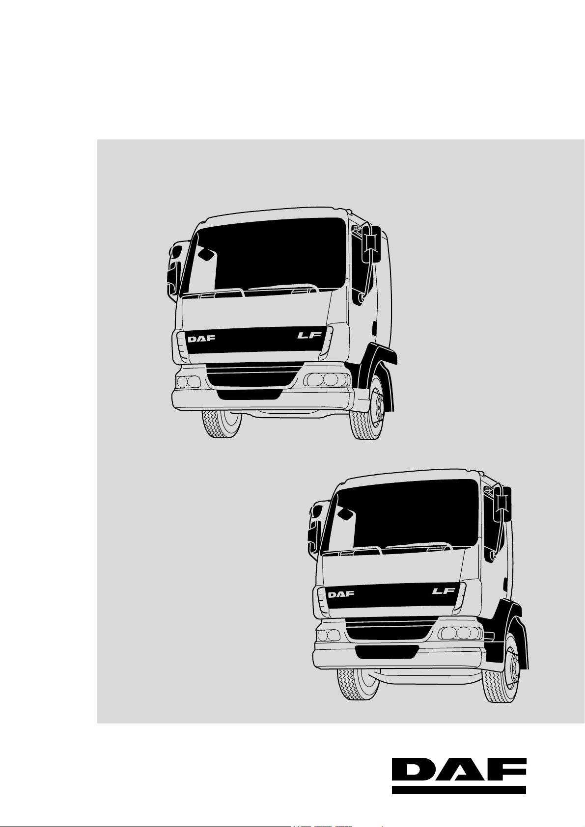
Maintenance manual
LF45/55
Page 2

Page 3

©200515 DAF Trucks N.V., Eindhoven,
The Netherlands.
In the interest of continuing product development,
DAF reserves the right to change specifications
or products at any time without prior notice.
No part of this publication may be reproduced
and/or published by printing, by photocopying, on
microfilm or in any way whatsoever without the
prior consent in writing of DAF Trucks N.V.
©
200515 DW13279204
Page 4

Page 5
ΛΦ45/55 series
STRUCTURE
Structure
TECHNICAL DATA
0
1
THREADED CONNECTIONS
2
FLUIDS, OIL AND LUBRICANTS
3
MAINTENANCE SCHEDULE
4
EXPLANATORY NOTES ON THE MAINTENANCE ACTIVITIES
5
©
200515
Page 6

Page 7
TECHNICAL DATA
ΛΦ45/55 series
0 Technical data
CONTENTS
Page Date
1. ENGINE, COOLING SYSTEM AND FUEL SYSTEM . . . . . . . . . . . . . . . . . . . . . 1-1 . . . . . 200515
1.1 General . . . . . . . . . . . . . . . . . . . . . . . . . . . . . . . . . . . . . . . . . . . . . . . . . . . 1-1 . . . . . 200515
1.2 Tightening torques. . . . . . . . . . . . . . . . . . . . . . . . . . . . . . . . . . . . . . . . . . . 1-2 . . . . . 200515
1.3 Filling capacities . . . . . . . . . . . . . . . . . . . . . . . . . . . . . . . . . . . . . . . . . . . . 1-3 . . . . . 200515
2. STEERING GEAR . . . . . . . . . . . . . . . . . . . . . . . . . . . . . . . . . . . . . . . . . . . . . . . . 2-1 . . . . . 200515
2.1 General . . . . . . . . . . . . . . . . . . . . . . . . . . . . . . . . . . . . . . . . . . . . . . . . . . . 2-1 . . . . . 200515
2.2 Tightening torques. . . . . . . . . . . . . . . . . . . . . . . . . . . . . . . . . . . . . . . . . . . 2-2 . . . . . 200515
3. DRIVE SHAFTS, DRIVE AND CHASSIS . . . . . . . . . . . . . . . . . . . . . . . . . . . . . . 3-1 . . . . . 200515
3.1 General . . . . . . . . . . . . . . . . . . . . . . . . . . . . . . . . . . . . . . . . . . . . . . . . . . . 3-1 . . . . . 200515
3.2 Tightening torques. . . . . . . . . . . . . . . . . . . . . . . . . . . . . . . . . . . . . . . . . . . 3-2 . . . . . 200515
3.3 Filling capacities . . . . . . . . . . . . . . . . . . . . . . . . . . . . . . . . . . . . . . . . . . . . 3-6 . . . . . 200515
Contents
0
©
200515 1
Page 8
TECHNICAL DATA
0
Contents
ΛΦ45/55 series
2
©
200515
Page 9
TECHNICAL DATA
ΛΦ45/55 series
Engine, cooling system and fuel system
1. ENGINE, COOLING SYSTEM AND FUEL SYSTEM
1.1 GENERAL
Valve clearance, BE engine and CE engine
Inspection dimension, valve clearance (cold)
Inlet 0.15 - 0.40 mm
Outlet 0.40 - 0.75 mm
Setting dimension, valve clearance (cold)
Inlet 0.25 mm
Outlet 0.50 mm
0
©
200515 1-1
Page 10
TECHNICAL DATA
0
Engine, cooling system and fuel system
1.2 TIGHTENING TORQUES
The tightening torques specified in this section
are different from the standard tightening torques
cited in the overview of the standard tightening
torques. The other threaded connections not
specified must therefore be tightened to the
torque cited in the overview of standard
tightening torques.
When attachment bolts and nuts are replaced, it
is important that - unless stated otherwise - these
bolts and nuts are of exactly the same length and
property class as those removed.
Lubrication system, BE engine and CE engine
Oil drain plug 60 Nm
Valve gear, BE engine and CE engine
Valve cover attachment bolts 10 Nm
ΛΦ45/55 series
1-2
©
200515
Page 11
TECHNICAL DATA
ΛΦ45/55 series
Engine, cooling system and fuel system
1.3 FILLING CAPACITIES
BE engine lubrication system
Total capacity (including oil cooler and oil filter) approx. 13.0 litres
Capacity of oil sump, maximum level approx. 11.0 litres
Capacity of oil sump, minimum level approx. 8.9 litres
BE engine cooling system
Cooling system approx. 20 litres
CE engine lubrication system
Total capacity (including oil cooler and oil filter) approx. 19.5 litres
Capacity of oil sump, maximum level approx. 17.5 litres
Capacity of oil sump, minimum level approx. 15.5 litres
CE engine cooling system
Cooling system approx. 22 litres
0
©
200515 1-3
Page 12
TECHNICAL DATA
0
Engine, cooling system and fuel system
ΛΦ45/55 series
1-4
©
200515
Page 13
TECHNICAL DATA
ΛΦ45/55 series
2. STEERING GEAR
2.1 GENERAL
Maximum axial steering ball joint play 1.5 mm
Steering gear
0
©
200515 2-1
Page 14
TECHNICAL DATA
0
Steering gear
2.2 TIGHTENING TORQUES
The tightening torques specified in this section
are different from the standard tightening torques
cited in the overview of the standard tightening
torques. The other threaded connections not
specified must therefore be tightened to the
torque cited in the overview of standard
tightening torques.
When attachment bolts and nuts are replaced, it
is important that - unless stated otherwise - these
bolts and nuts are of exactly the same length and
property class as those removed.
High-pressure filter, RAS-EC system
Filter cap 15 Nm
ΛΦ45/55 series
2-2
©
200515
Page 15
TECHNICAL DATA
ΛΦ45/55 series
3. DRIVE SHAFTS, DRIVE AND CHASSIS
3.1 GENERAL
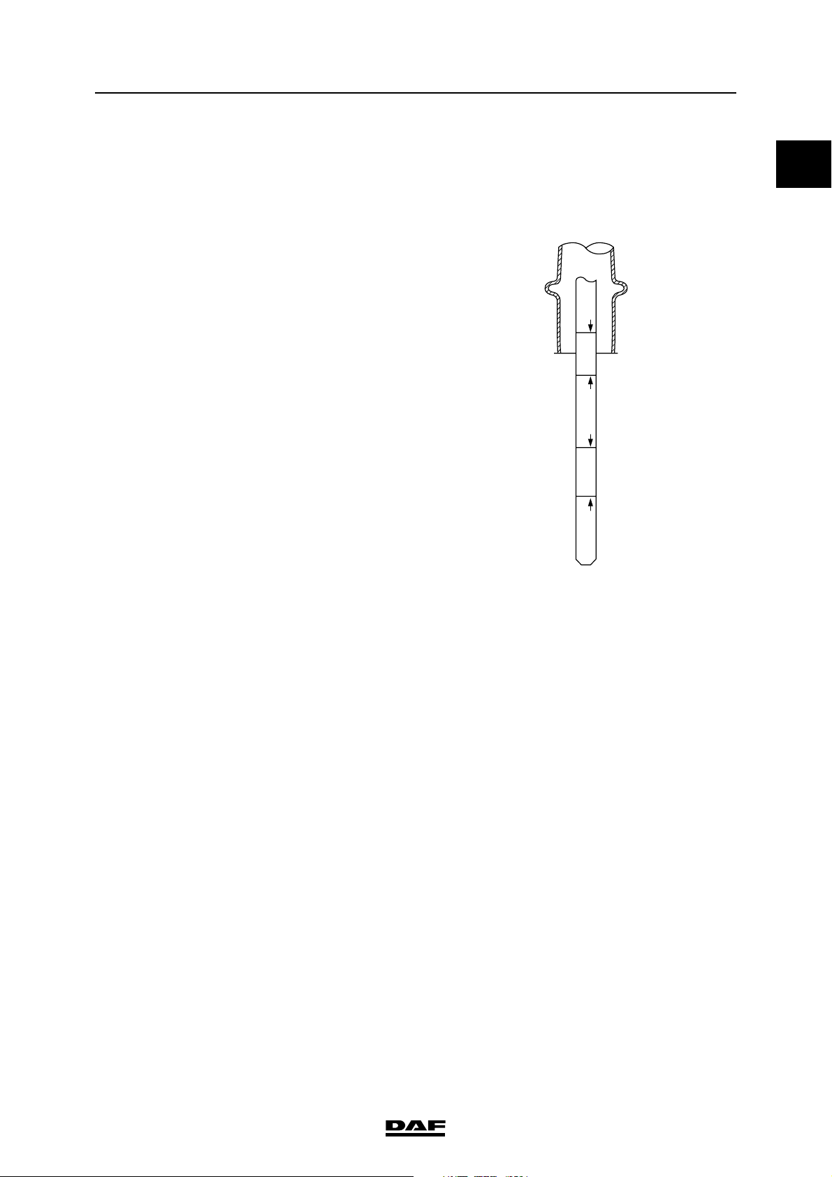
Allison gearbox
The oil level when cold must be on the "Cold full"
mark.
Drive shafts, drive and chassis
HOT
FULL
HOT
ADD
FULL
COLD
0
Dipstick readings:
"Cold add" add when cold
"Cold full" full when cold
"Hot add" add when hot
"Hot full" full when hot
5.12 rear axle
Sealant for crown wheel guide bolt Loctite 572
F36/F48 front axle
Wheel bearing play (to adjust play) 0.05 - 0.20 mm
ADD
COLD
W 3 03 099
©
200515 3-1
Page 16
TECHNICAL DATA
0
Drive shafts, drive and chassis
3.2 TIGHTENING TORQUES
The tightening torques stated in this section are
different from the standard tightening torques
stated in the overview of the standard tightening
torques. The other threaded connections not
specified must therefore be tightened to the
torque stated in the overview of standard
tightening torques.
When attachment bolts and nuts are to be
replaced, it is important - unless stated otherwise that these bolts and nuts are of exactly the same
length and property class as the removed ones.
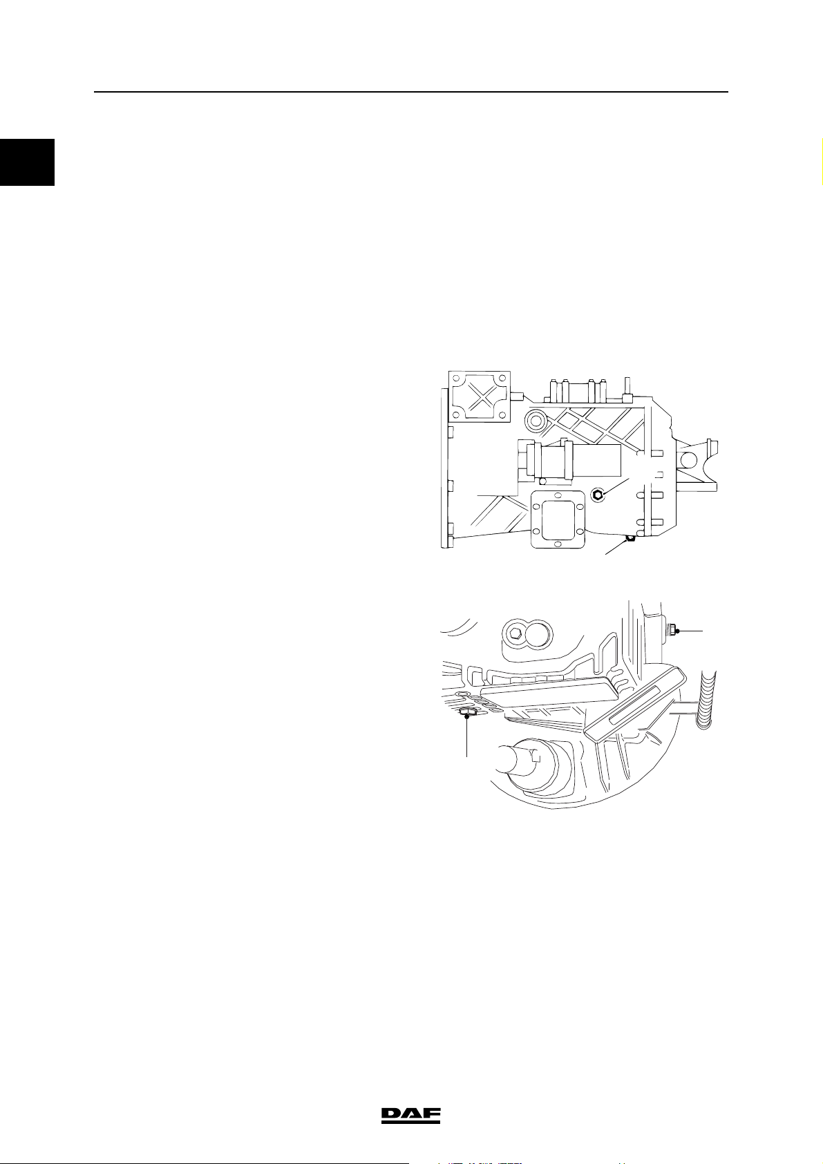
ZF S5-42 gearbox
Level check/filler
plug (2) 50 Nm
Drain plug (1) 50 Nm
ΛΦ45/55 series
2
ZF 6S-850 gearbox
Level check/filler
plug (1) 50 Nm
Drain plug (2) 60 Nm
1
V3 00 395
1
2
V3 00 884
3-2
©
200515
Page 17
TECHNICAL DATA
ΛΦ45/55 series
Eaton FS6309A gearbox
Level check/filler
plug (1) 50 Nm
Drain plug/oil
strainer (4) 50 Nm
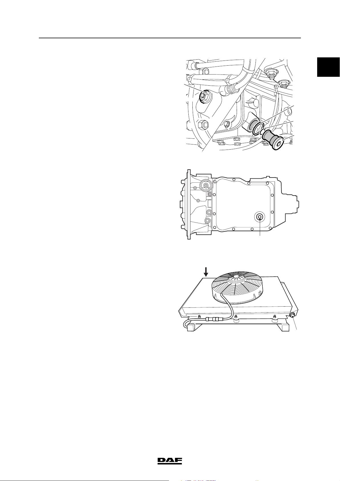
Allison 1000 & 2000 automatic gearboxes
Gearbox drain
plug (1) 35 Nm
Drive shafts, drive and chassis
0
1
2
3
4
V3 00 376
Oil cooler air bleed
plug (1) 28 Nm
Oil cooler drain
plug (2) 28 Nm
1
V3 00 885
1
2
V3 00 883
©
200515 3-3
Page 18

TECHNICAL DATA
0
Drive shafts, drive and chassis
Allison MD3060 automatic gearbox
Drain plug (1) 28 Nm
Oil filter cover
attachment bolts (2) 55 Nm
F36/F48 front axle
Tightening torque for
brake calliper
attachment bolts 213 Nm
Tightening sequence
for attachment bolts
Hub lock nut 75 Nm
ΛΦ45/55 series
2
1
V300371
6 23 1 54
Front axles
M18 x 1.5 wheel nut
(LF 45 version 6/8 ton GVW) 370 Nm
M20 x 1.5 wheel nut
(LF 45 version 10/11/12 ton GVW) 485 Nm
M20 x 1.5 wheel nut
(LF 55 version 13/14/15 ton GVW) 485 Nm
M22 x 1.5 wheel nut
(LF 55 version 18 ton GVW) 700 Nm
LF 45 U-bolt nut 215 Nm
U-bolt nut, LF 55 version 13/14/15 ton GVW 470 Nm
U-bolt nut, LF 55 version 18 ton GVW 535 Nm
(1) Retighten after 100 km.
(2) Evenly tighten the two U-bolt nuts alternately.
R600520
(1)
(1)
(1)
(1)
(2)
(2)
(2)
3-4
©
200515
Page 19
TECHNICAL DATA
ΛΦ45/55 series
Rear axles
M18 x 1.5 wheel nut
(LF 45 version 6/8 ton GVW) 370 Nm
M20 x 1.5 wheel nut
(LF 45 version 10/11/12 ton GVW) 485 Nm
M20 x 1.5 wheel nut
(LF 55 version 13/14/15 ton GVW) 485 Nm
M22 x 1.5 wheel nut
(LF 55 version 18 ton GVW) 700 Nm
LF 45 U-bolt nut 470 Nm
U-bolt nut, LF 55 version 13/14/15 ton GVW 470 Nm
U-bolt nut, LF 55 version 18 ton GVW 700 Nm
(1) Retighten after 100 km.
(2) Evenly tighten the two U-bolt nuts alternately.
1132 rear axle
Filler and drain plugs/hub plugs (Torx) 85 Nm
Differential
Locking nut of crown wheel guide bolt 110 Nm
Differential drain plug 54 Nm
Drive shafts, drive and chassis
(1)
(1)
(1)
(1)
(2)
(2)
(2)
0
Drive shafts
5/16" UNF clamping bracket
Tightening torque 38 Nm
Retightening torque 36 Nm
3/8" UNF clamping bracket
Tightening torque 70 Nm
Retightening torque 67 Nm
©
200515 3-5
Page 20

TECHNICAL DATA
0
Drive shafts, drive and chassis
3.3 FILLING CAPACITIES
ZF gearboxes
S5-42 approx. 3.2 litres
6S-850 approx. 7.5 litres
Eaton gearboxes
FS6309A approx. 8.5 litres
Allison automatic gearboxes
1000 & 2000 approx. 10 litres
MD3060 approx. 20 litres
Note:
The above filling capacities are approximate
capacities, excluding external pipes and cooler
Differential
5.10 approx. 4.0 litres
5.12 approx. 4.0 litres
5.14 approx. 4.0 litres
8.20 approx. 8.0 litres
10.20 approx. 9.0 litres
10.26 approx. 9.0 litres
11.26 approx. 9.0 litres
ΛΦ45/55 series
1132 axle differential
Minimum caster approx. 15 litres
Maximum caster approx. 17.5 litres
Wheel hub
5.10 0.25 litre per hub
5.12 0.25 litre per hub
5.14 0.25 litre per hub
8.20 0.25 litre per hub
3-6
©
200515
Page 21
THREADED CONNECTIONS
ΛΦ45/55 series
2 Threaded connections
CONTENTS
Page Date
1. THREADED CONNECTIONS . . . . . . . . . . . . . . . . . . . . . . . . . . . . . . . . . . . . . . . 1-1 . . . . . 200515
1.1 General . . . . . . . . . . . . . . . . . . . . . . . . . . . . . . . . . . . . . . . . . . . . . . . . . . . 1-1 . . . . . 200515
Contents
2
©
200515 1
Page 22
THREADED CONNECTIONS
2
Contents
ΛΦ45/55 series
2
©
200515
Page 23
THREADED CONNECTIONS
ΛΦ45/55 series
1. THREADED CONNECTIONS
1.1 GENERAL
The components may have threaded connections
that have been treated with lubricant (dipped
threaded connection). Galvanised bolts and nuts
are wax dipped in the factory. Black annealed
and phosphatised bolts and nuts are oil dipped.
The advantage of using dipped nuts and bolts is
that friction during tightening is reduced, so that
the specified pre-tension force can be accurately
obtained. The tightening torque can be reduced
while the pre-tension force remains the same.
To achieve a small spread in the pre-tension
force, the dipped threaded connection must be
tightened accurately.
Therefore, always use a reliable torque wrench
that provides a high degree of accuracy.
Note:
Have torque wrenches regularly inspected and
calibrated.
Threaded connections
2
Re-use of fasteners (bolt/nut/threaded end)
1. Clean the thread (take particular care to
remove locking compound residues) and the
clamping faces
2. Check the thread for damage.
To do so, manually screw a new nut/bolt onto
the thread to be checked.
If the new nut/bolt cannot be fully handscrewed onto the entire thread of the
fastener to be checked, the fastener is not
allowed to be re-used.
3. Apply one drop of engine oil to the upper turn
of the bolt (threaded end)/lower turn of the
nut and one drop to the clamping faces
(other lubricants are not allowed).
4. If a locking compound has been specified, oil
should not be applied to the thread.
©
200515 1-1
Page 24
THREADED CONNECTIONS
2
Threaded connections
The following applies to all threaded
connections (for both new and used
vehicles):
- in the case of standard connections, apply
the lubricant before fitting, and (re)tighten in
accordance with the standard for dipped
bolts;
- in the case of special connections, apply the
lubricant before fitting, and (re)tighten in
accordance with the values specified in the
instructions.
The instructions for using lubricants also apply to
new bolts from the warehouse. Dry threaded
connections may not be used because of their
highly variable friction coefficients.
Please consult the workshop manual
for the specified tightening torque.
}
ΛΦ45/55 series
1-2
©
200515
Page 25
FLUIDS, OIL AND LUBRICANTS
ΛΦ45/55 series
3 Fluids, oil and lubricants
CONTENTS
Page Date
1. SPECIFICATIONS. . . . . . . . . . . . . . . . . . . . . . . . . . . . . . . . . . . . . . . . . . . . . . . . 1-1 . . . . . 200515
1.1 General . . . . . . . . . . . . . . . . . . . . . . . . . . . . . . . . . . . . . . . . . . . . . . . . . . . 1-1 . . . . . 200515
Contents
3
©
200515 1
Page 26
FLUIDS, OIL AND LUBRICANTS
3
Contents
ΛΦ45/55 series
2
©
200515
Page 27
FLUIDS, OIL AND LUBRICANTS
ΛΦ45/55 series
1. SPECIFICATIONS
1.1 GENERAL
IN ORDER TO SATISFY THE WARRANTY
CONDITIONS AND GUARANTEE THE
LIFESPAN, SAFETY AND RELIABILITY OF
DAF PRODUCTS, IT IS OF THE UTMOST
IMPORTANCE THAT THE CORRECT FLUIDS,
OIL AND LUBRICANTS, COOLANT AND FUEL
ARE USED AND THAT THE REQUIRED
REPLACEMENT INTERVALS ARE
OBSERVED.
Lubricant, engine coolant and fuel additives - of
whatever type - must not be used except in those
circumstances specified by DAF.
Always follow the safety instructions below and
the instructions that are supplied with the product.
Ask your lubricant and fuel supplier(s) whether
the products supplied comply with DAF
specifications.
Specifications
3
DAF is not liable for damage or problems in
the following instances:
1. use of oil of a lower grade than specified.
2. use of oil of a different viscosity than
specified.
3. if the change interval is exceeded.
4. if fuel, lubricants or coolants have been
used which do not meet the requirements
specified by DAF.
Avoid contact with:
Lubricants
}
Coolant
Fuel
Clutch fluid
In the event of contact with the skin:
remove the liquid with paper or a
cloth, wash with soap and water. If
irritation persists, consult a doctor.
In the event of contact with the eyes:
remove with a cloth and rinse with
water. If irritation persists, consult a
doctor.
If swallowed: DO NOT induce
vomiting. Rinse mouth, drink two
glasses of water and consult a
doctor.
In the event of inhalation: get fresh
air and rest.
Note:
Refer to the "Fluids and lubricants" specification
manual for the prescribed fluid, oil and lubricant
specifications.
©
200515 1-1
Page 28
FLUIDS, OIL AND LUBRICANTS
3
Specifications
ΛΦ45/55 series
1-2
©
200515
Page 29
MAINTENANCE SCHEDULE
ΛΦ45/55 series
4 Maintenance schedule
CONTENTS
Page Date
1. MAINTENANCE INTERVALS . . . . . . . . . . . . . . . . . . . . . . . . . . . . . . . . . . . . . . . 1-1 . . . . . 200515
1.1 Maintenance schedule. . . . . . . . . . . . . . . . . . . . . . . . . . . . . . . . . . . . . . . . 1-1 . . . . . 200515
1.2 Explanatory notes on the maintenance schedule . . . . . . . . . . . . . . . . . . . 1-2 . . . . . 200515
1.3 Effect of diesel fuel and PTO hours on maintenance intervals . . . . . . . . . 1-4 . . . . . 200515
1.4 Maintenance in special operating conditions. . . . . . . . . . . . . . . . . . . . . . . 1-4 . . . . . 200515
1.5 First service inspection . . . . . . . . . . . . . . . . . . . . . . . . . . . . . . . . . . . . . . . 1-4 . . . . . 200515
2. MAINTENANCE ACTIVITIES . . . . . . . . . . . . . . . . . . . . . . . . . . . . . . . . . . . . . . . 2-1 . . . . . 200515
2.1 Overview of maintenance activities for the first service inspection . . . . . . 2-1 . . . . . 200515
2.2 Overview of annual maintenance activities . . . . . . . . . . . . . . . . . . . . . . . . 2-2 . . . . . 200515
2.3 Overview of mileage-dependent maintenance activities . . . . . . . . . . . . . . 2-4 . . . . . 200515
Contents
4
©
200515 1
Page 30
MAINTENANCE SCHEDULE
4
Contents
ΛΦ45/55 series
2
©
200515
Page 31
MAINTENANCE SCHEDULE
ΛΦ45/55 series
1. MAINTENANCE INTERVALS
1.1 MAINTENANCE SCHEDULE
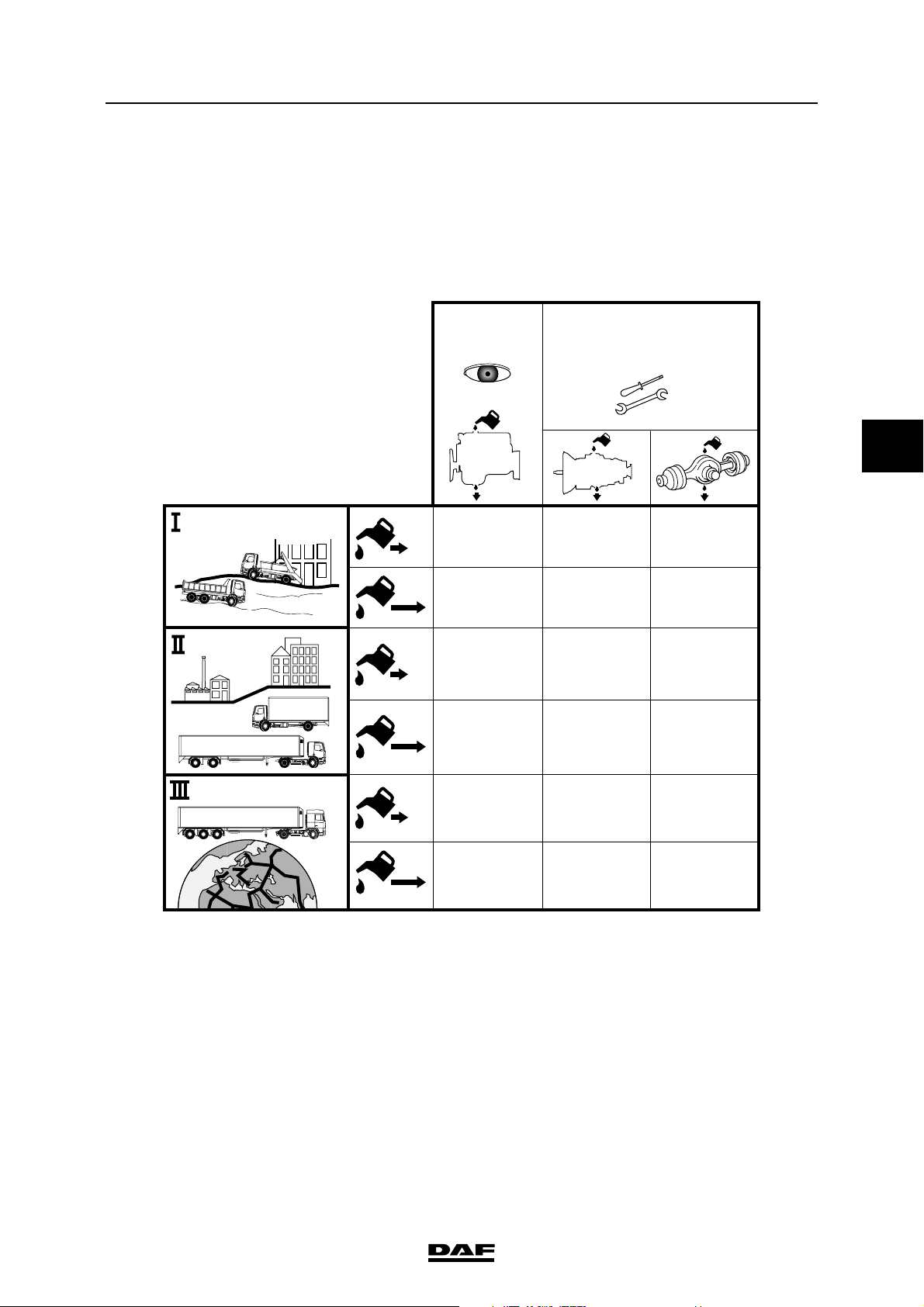
The service intervals stated in the maintenance
schedule are based on use of the oils and fuels
specified by DAF.
Maintenance
schedule
LF45
LF55
X service
+
40.000 km
Y service
1x per YEAR
(1)
1 year
max. 100.000 km
Maintenance intervals
+
4
1 year
max. 100.000 km
Ext.
Ext.
Ext.
1. Automatic gearboxes are subject to different
changing intervals; see maintenance
schedule notes. Extended changing interval
not permitted for ZF 6S-850 gearbox.
2. Changing interval for 1132 rear axle
450,000 km max.
40.000 km
40.000 km
3 year
max. 180.000 km
1 year
max. 100.000 km
3 year
max. 300.000 km
1 year
max. 150.000 km
3 year
max. 450.000 km
2 year
max. 120.000 km
1 year
max. 100.000 km
3 year
max. 300.000 km
1 year
max. 150.000 km
3 year
max. 300.000 km
(2)
G000318
©
200515 1-1
Page 32
MAINTENANCE SCHEDULE
4
Maintenance intervals
1.2 EXPLANATORY NOTES ON THE MAINTENANCE SCHEDULE
Maintenance group classification
Depending on the use to which the vehicle is put,
the vehicle is placed in maintenance group
I, II or III.
Maintenance group I
Operation on building sites, in quarries, etc.
- Operation on unmetalled roads
- Traffic in dusty conditions
- Sanitation department vehicles
- Distribution transport with an annual mileage
of up to 30,000 km.
Maintenance group II
Urban and regional transport
- Distribution traffic in urban areas
- Traffic between adjacent villages/cities
Maintenance group III
(Inter)national traffic
ΛΦ45/55 series
- Long-distance/very long-distance traffic
Standard changing interval
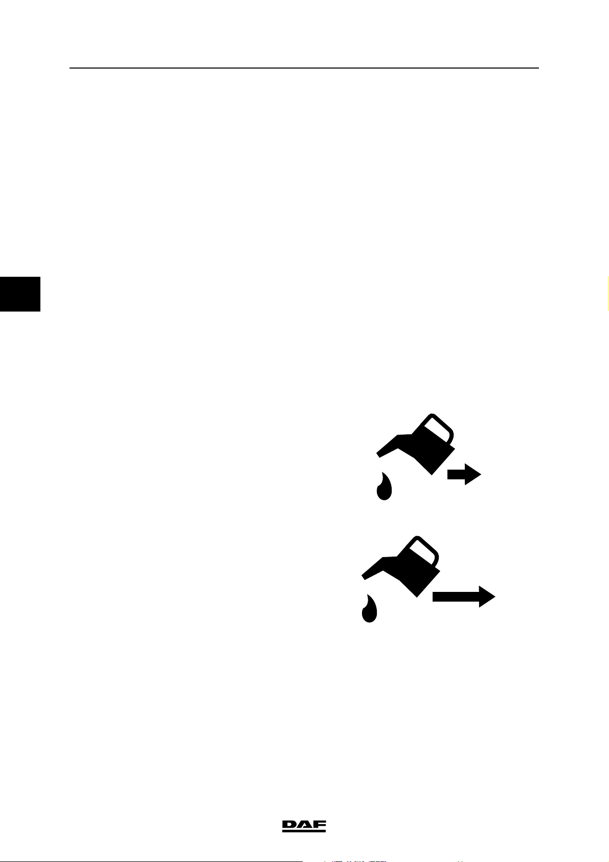
This is the standard changing interval symbol.
See the "Fluids and lubricants" specifications
manual for the prescribed oil specification.
Extended changing interval
This is the extended changing interval symbol.
If the prescribed oil specification and any
additional conditions (see specification manual
"Fluids and lubricants") are complied with, an
extended changing interval may be applied.
G0 00 230
Ext.
G0 00 229
1-2
©
200515
Page 33
MAINTENANCE SCHEDULE
ΛΦ45/55 series
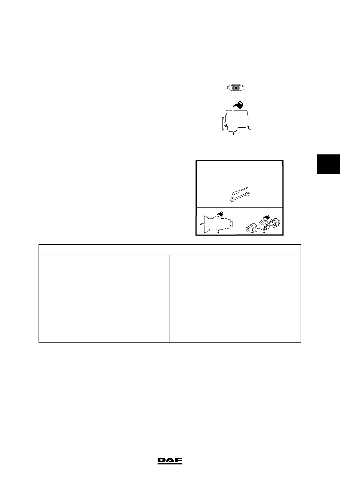
X service
This is the symbol for an X service.
An X service is a mileage-dependent
maintenance check which consists of changing
the engine oil plus a number of visual inspections.
Note:
An X service must be carried out at least once a
year.
Y service
This is the symbol for a Y service.
A Y service is an annual maintenance check
consisting of several maintenance activities plus
changing of the gearbox and rear axle oil.
Note:
If the prescribed oil specification (see
specification manual "Fluids and lubricants") is
complied with, an extended changing interval
may be applied.
Automatic gearboxes are subject to different
changing intervals.
Maintenance intervals
X service
+
G000086
Y service
1x per YEAR
+
(1)
G000087
4
Automatic Allison gearbox
Maintenance group I Standard changing interval 1 year/maximum
40,000 km
Extended changing interval 3 years/maximum
80,000 km
Maintenance group II Standard changing interval 1 year/maximum
40,000 km
Extended changing interval 3 years/maximum
160,000 km
Maintenance group III Standard changing interval 1 year/maximum
40,000 km
Extended changing interval 3 years/maximum
160,000 km
©
200515 1-3
Page 34

MAINTENANCE SCHEDULE
4
Maintenance intervals
ΛΦ45/55 series
1.3 EFFECT OF DIESEL FUEL AND PTO HOURS ON MAINTENANCE INTERVALS
Diesel fuels
Sulphur content Engine oil change interval
> 0,2% Halve interval to max. of 25,000 km
PTO hours
PTO hours should be converted into mileage
according to the following formula:
1 PTO hour = 40 km
1.4 MAINTENANCE IN SPECIAL OPERATING CONDITIONS
Contact a DAF dealer/main branch or importer for
vehicles used in very specific or heavy
conditions.
The service intervals can be modified, if
necessary, in consultation with the dealer/main
branch or importer to fit the appropriate operating
conditions.
1.5 FIRST SERVICE INSPECTION
The first service inspection should be carried out
between the first 7,500 and 10,000 km or at most
8 weeks after delivery of the vehicle, whichever
comes first.
1-4
©
200515
Page 35
MAINTENANCE SCHEDULE
ΛΦ45/55 series
Maintenance activities
2. MAINTENANCE ACTIVITIES
2.1 OVERVIEW OF MAINTENANCE ACTIVITIES FOR THE FIRST SERVICE
INSPECTION
- Replacing the automatic gearbox oil filters
4
©
200515 2-1
Page 36
MAINTENANCE SCHEDULE
4
Maintenance activities
ΛΦ45/55 series
2.2 OVERVIEW OF ANNUAL MAINTENANCE ACTIVITIES
ANNUAL MAINTENANCE ACTIVITIES (Y-SERVICE)
"Correct, if necessary, after inspection"
CAB AND ELECTRICAL SYSTEM
O Check pedal rubbers
O Check whether the latest version of the ITS manual is kept in the cab
O Replace the cab filter element - See note 1 Replaced O Yes O No
O Check the fluid level of the cab tilting pump
O Check cab fastening
ENGINE, COOLING SYSTEM AND FUEL SYSTEM
O Replace the air filter element
O Check the air inlet dust trapping valve
O Check the vibration damper (vulcanised version)
O Check/adjust the valve clearance - See note 4 Done O Yes O No
O Check the coolant freezing point
O Change the coolant - See note 5 Changed O Yes O No
O Remove the fuel fine filter
STEERING GEAR AND BRAKE SYSTEM
O Check the steering ball joints
O Replace the air dryer filter element
O Check the brake cylinder fastening
O Check/adjust the load-dependent control valve
O Replace the steering gear filter element if the vehicle is equipped
with the RAS-EC system - See note 6 Replaced O Yes O No
O Replace the steering gear high-pressure filter if the vehicle is
equipped with the RAS-EC system - See note 6 Replaced O Yes O No
DRIVE AND CHASSIS
O Change the differential oil - See note 2 Changed O Yes O No
O Change the hub oil - See note 2 Changed O Yes O No
O Check operation of the differential lock
O Check the drive shaft play
O Check attachment of the clamp of the drive shaft universal joint
O Adjust the crown wheel guide bolt in case of a 5.12 rear axle
O Check for noticeable wheel bearing play in case of a 5.10, 5.12,
5.14 and 8.20 rear axle - See note 1 Done O Yes O No
O Change the gearbox oil - See note 3 Changed O Yes O No
O Replace the grease of grease-lubricated hubs, F36 and F48 front
axles - See note 1 Replaced O Yes O No
O Check the fifth wheel
O Check the trailer coupling
O Check superstructure attachment
O Lubricate according to Y-service lubrication schedule
OTHER ACTIVITIES
O Check whether there are any field actions that still need to be performed on the vehicle
2-2
©
200515
Page 37
MAINTENANCE SCHEDULE
ΛΦ45/55 series
Note:
1. Every 2 years.
2. For changing interval: see maintenance
schedule.
3. For changing interval: see maintenance
schedule.
When changing the gearbox oil in an
automatic gearbox, the automatic gearbox
oil filters must also be replaced.
4. Check the valve clearance at the 4
Y-service (at a maximum of 240,000 km) and
then check and adjust, where necessary,
every year.
th
5
- 6th- 7th... year).
5. Every 5 years.
6. Every 3 years.
th
Maintenance activities
4
©
200515 2-3
Page 38
MAINTENANCE SCHEDULE
4
Maintenance activities
ΛΦ45/55 series
2.3 OVERVIEW OF MILEAGE-DEPENDENT MAINTENANCE ACTIVITIES
MILEAGE-DEPENDENT MAINTENANCE ACTIVITIES (X-SERVICE)
"Correct if necessary after inspection"
CAB AND ELECTRICAL SYSTEM
O Check/clean the battery terminals
O Check/top up the battery fluid level
ENGINE, COOLING SYSTEM AND FUEL SYSTEM
O Change the engine oil
O Replace the oil filter
O Replace the fuel prefilter/water separator filter element
O Check for fuel leaks
O Check the poly-V belt Replaced O Yes O No
O Check the components and hose connections for leaks
O Check the radiator and intercooler for fouling
O Check the exhaust system
STEERING GEAR AND BRAKE SYSTEM
O Check the steering ball joint sleeve for damage
O Check the steering oil level
O Check the steering gear lines and connections
O Check the brake components and brake system for leaks
O Check the brake pad thickness and brake disc
DRIVE AND CHASSIS
O Check the clutch fluid level
O Check the clutch wear indicator
O Check the differential for leaks - See note 1
O Check the oil lubricated wheel hubs for leaks - See note 1
O Check the greased wheel hubs for leaks
O Check the gearbox for leaks - See note 2
O Clean gearbox vent and rear axle vent on "offroad/semi-offroad" vehicles
O Check the shock absorbers for attachment and leaks
O Check the condition and attachments of spring leaves, spring clamps and U-bolts
O Check the hinge points and axle suspension fastening (air suspension)
O Check the air suspension bellows
O Lubricate according to X-service lubrication schedule
OTHER ACTIVITIES
O Check whether "Field actions" still need to be carried out on the vehicle
Note:
1. For the changing interval see the
maintenance schedule.
2. For the changing interval see the
maintenance schedule.
When changing the gearbox oil in an
automatic gearbox, the automatic gearbox
oil filters must also be replaced.
2-4
©
200515
Page 39
EXPLANATORY NOTES ON THE MAINTENANCE ACTIVITIES
ΛΦ45/55 series
5 Explanatory notes on the maintenance activities
CONTENTS
Page Date
1. SAFETY INSTRUCTIONS. . . . . . . . . . . . . . . . . . . . . . . . . . . . . . . . . . . . . . . . . . 1-1 . . . . . 200515
1.1 Safety instructions . . . . . . . . . . . . . . . . . . . . . . . . . . . . . . . . . . . . . . . . . . . 1-1 . . . . . 200515
2. GENERAL . . . . . . . . . . . . . . . . . . . . . . . . . . . . . . . . . . . . . . . . . . . . . . . . . . . . . . 2-1 . . . . . 200515
2.1 Introduction . . . . . . . . . . . . . . . . . . . . . . . . . . . . . . . . . . . . . . . . . . . . . . . . 2-1 . . . . . 200515
2.2 Technical information . . . . . . . . . . . . . . . . . . . . . . . . . . . . . . . . . . . . . . . . 2-1 . . . . . 200515
2.3 Warning symbol. . . . . . . . . . . . . . . . . . . . . . . . . . . . . . . . . . . . . . . . . . . . . 2-2 . . . . . 200515
2.4 Environment . . . . . . . . . . . . . . . . . . . . . . . . . . . . . . . . . . . . . . . . . . . . . . . 2-2 . . . . . 200515
2.5 Parts . . . . . . . . . . . . . . . . . . . . . . . . . . . . . . . . . . . . . . . . . . . . . . . . . . . . . 2-3 . . . . . 200515
2.6 Maintenance guidelines. . . . . . . . . . . . . . . . . . . . . . . . . . . . . . . . . . . . . . . 2-4 . . . . . 200515
3. INSPECTION AND ADJUSTMENT. . . . . . . . . . . . . . . . . . . . . . . . . . . . . . . . . . . 3-1 . . . . . 200515
Cab and electrical system
3.1 Checking pedal rubbers. . . . . . . . . . . . . . . . . . . . . . . . . . . . . . . . . . . . . . . 3-1 . . . . . 200515
3.2 Checking the battery fluid level . . . . . . . . . . . . . . . . . . . . . . . . . . . . . . . . . 3-1 . . . . . 200515
3.3 Checking the battery terminals . . . . . . . . . . . . . . . . . . . . . . . . . . . . . . . . . 3-2 . . . . . 200515
3.4 Checking the fluid level of the cab tilting pump . . . . . . . . . . . . . . . . . . . . . 3-2 . . . . . 200515
3.5 Checking the cab fastening . . . . . . . . . . . . . . . . . . . . . . . . . . . . . . . . . . . . 3-3 . . . . . 200515
Engine, cooling system and fuel system
3.6 Checking the vibration damper (vulcanised version) of the BE engine . . . 3-3 . . . . . 200515
3.7 Bleeding the fuel system . . . . . . . . . . . . . . . . . . . . . . . . . . . . . . . . . . . . . . 3-4 . . . . . 200515
3.8 Checking the engine oil level . . . . . . . . . . . . . . . . . . . . . . . . . . . . . . . . . . . 3-5 . . . . . 200515
3.9 Checking and adjusting BE engine valve clearance . . . . . . . . . . . . . . . . . 3-6 . . . . . 200515
3.10 Inspection and adjustment, CE engine valve clearance . . . . . . . . . . . . . . 3-8 . . . . . 200515
3.11 Checking the poly-V-belt . . . . . . . . . . . . . . . . . . . . . . . . . . . . . . . . . . . . . . 3-10 . . . . 200515
3.12 Checking the coolant freezing point . . . . . . . . . . . . . . . . . . . . . . . . . . . . . 3-10 . . . . 200515
3.13 Checking for fuel leaks . . . . . . . . . . . . . . . . . . . . . . . . . . . . . . . . . . . . . . . 3-11 . . . . 200515
3.14 Checking the components and hose connections for leaks . . . . . . . . . . . 3-11 . . . . 200515
3.15 Checking the exhaust system . . . . . . . . . . . . . . . . . . . . . . . . . . . . . . . . . . 3-11 . . . . 200515
3.16 Checking the radiator and intercooler for fouling. . . . . . . . . . . . . . . . . . . . 3-11 . . . . 200515
3.17 Check the air inlet dust trapping valve. . . . . . . . . . . . . . . . . . . . . . . . . . . . 3-12 . . . . 200515
Steering gear and brake system
3.18 Checking the steering ball joint sleeve for damage. . . . . . . . . . . . . . . . . . 3-12 . . . . 200515
3.19 Checking the steering ball joints . . . . . . . . . . . . . . . . . . . . . . . . . . . . . . . . 3-13 . . . . 200515
3.20 Checking the steering oil level. . . . . . . . . . . . . . . . . . . . . . . . . . . . . . . . . . 3-14 . . . . 200515
3.21 Checking the steering gear lines and connections . . . . . . . . . . . . . . . . . . 3-15 . . . . 200515
3.22 Checking the brake components and brake system for leaks. . . . . . . . . . 3-16 . . . . 200515
3.23 Checking the brake cylinder fastening. . . . . . . . . . . . . . . . . . . . . . . . . . . . 3-16 . . . . 200515
3.24 Checking the brake pad thickness and brake disc . . . . . . . . . . . . . . . . . . 3-17 . . . . 200515
3.25 Inspection and adjustment, load sensing valve, air suspension . . . . . . . . 3-19 . . . . 200515
3.26 Inspection and adjustment, load sensing valve, leaf suspension . . . . . . . 3-21 . . . . 200515
Drive and chassis
3.27 Checking the differential for leaks . . . . . . . . . . . . . . . . . . . . . . . . . . . . . . . 3-23 . . . . 200515
3.28 Checking the operation of the differential lock. . . . . . . . . . . . . . . . . . . . . . 3-23 . . . . 200515
3.29 Check the drive shaft play . . . . . . . . . . . . . . . . . . . . . . . . . . . . . . . . . . . . . 3-24 . . . . 200515
3.30 Inspecting the fifth wheel . . . . . . . . . . . . . . . . . . . . . . . . . . . . . . . . . . . . . . 3-24 . . . . 200515
3.31 Checking the trailer coupling . . . . . . . . . . . . . . . . . . . . . . . . . . . . . . . . . . . 3-25 . . . . 200515
3.32 Check the superstructure attachment . . . . . . . . . . . . . . . . . . . . . . . . . . . . 3-26 . . . . 200515
3.33 Check the clutch fluid level . . . . . . . . . . . . . . . . . . . . . . . . . . . . . . . . . . . . 3-27 . . . . 200515
3.34 Check the clutch wear indicator. . . . . . . . . . . . . . . . . . . . . . . . . . . . . . . . . 3-28 . . . . 200515
3.35 Checking the gearbox for leaks . . . . . . . . . . . . . . . . . . . . . . . . . . . . . . . . . 3-28 . . . . 200515
3.36 Checking automatic gearbox oil level . . . . . . . . . . . . . . . . . . . . . . . . . . . . 3-29 . . . . 200515
3.37 Inspection of oil lubricated wheel hubs for leaks . . . . . . . . . . . . . . . . . . . . 3-31 . . . . 200515
Contents
5
©
200515 1
Page 40

EXPLANATORY NOTES ON THE MAINTENANCE ACTIVITIES
5
Contents
3.38 Checking greased wheel hubs for leaks . . . . . . . . . . . . . . . . . . . . . . . . . . 3-32 . . . . 200515
3.39 Checking the shock absorbers for attachment and leaks . . . . . . . . . . . . . 3-33 . . . . 200515
3.40 Checking the condition and attachments of spring leaves, spring clamps
and U-bolts . . . . . . . . . . . . . . . . . . . . . . . . . . . . . . . . . . . . . . . . . . . . . . . . 3-33 . . . . 200515
3.41 Checking the hinge points and axle suspension fastening (air suspension) 3-34 . . . . 200515
3.42 Checking the air suspension bellows . . . . . . . . . . . . . . . . . . . . . . . . . . . . 3-35 . . . . 200515
3.43 Adjusting the crown wheel guide bolt . . . . . . . . . . . . . . . . . . . . . . . . . . . . 3-36 . . . . 200515
3.44 Inspecting the rear axle wheel bearing play . . . . . . . . . . . . . . . . . . . . . . . 3-37 . . . . 200515
3.45 Checking the clamp of the drive shaft universal joint. . . . . . . . . . . . . . . . . 3-38 . . . . 200515
4. REMOVAL AND INSTALLATION. . . . . . . . . . . . . . . . . . . . . . . . . . . . . . . . . . . . 4-1 . . . . . 200515
Cab and electrical system
4.1 Removal and installation, interior filter element. . . . . . . . . . . . . . . . . . . . . 4-1 . . . . . 200515
Engine, cooling system and fuel system
4.2 Removal and installation, air filter element . . . . . . . . . . . . . . . . . . . . . . . . 4-2 . . . . . 200515
4.3 Removal and installation, lubricating oil filter. . . . . . . . . . . . . . . . . . . . . . . 4-3 . . . . . 200515
4.4 Removal and installation, fuel fine filter . . . . . . . . . . . . . . . . . . . . . . . . . . . 4-4 . . . . . 200515
4.5 Removal and installation, fuel prefilter/water separator. . . . . . . . . . . . . . . 4-5 . . . . . 200515
4.6 Removal and installation, valve cover . . . . . . . . . . . . . . . . . . . . . . . . . . . . 4-6 . . . . . 200515
Steering gear and brake system
4.7 Removal and installation, air dryer filter element. . . . . . . . . . . . . . . . . . . . 4-7 . . . . . 200515
4.8 Removal and installation, filter element in the reservoir of the RAS-EC
steering gear . . . . . . . . . . . . . . . . . . . . . . . . . . . . . . . . . . . . . . . . . . . . . . . 4-9 . . . . . 200515
4.9 Removal and installation, high-pressure filter of the RAS-EC steering
gear . . . . . . . . . . . . . . . . . . . . . . . . . . . . . . . . . . . . . . . . . . . . . . . . . . . . . . 4-10 . . . . 200515
4.10 Removal and installation, F36/F48 front axle wheel hub. . . . . . . . . . . . . . 4-11 . . . . 200515
4.11 Removal and installation, F36/F48 front axle hub seal . . . . . . . . . . . . . . . 4-15 . . . . 200515
Drive and chassis
4.12 Removal and installation, automatic gearbox oil filters . . . . . . . . . . . . . . . 4-16 . . . . 200515
ΛΦ45/55 series
Page Date
5. DRAINING AND FILLING . . . . . . . . . . . . . . . . . . . . . . . . . . . . . . . . . . . . . . . . . . 5-1 . . . . . 200515
Cab and electrical system
5.1 Topping up battery fluid . . . . . . . . . . . . . . . . . . . . . . . . . . . . . . . . . . . . . . . 5-1 . . . . . 200515
Engine, cooling system and fuel system
5.2 Draining and replenishing the engine oil . . . . . . . . . . . . . . . . . . . . . . . . . . 5-2 . . . . . 200515
5.3 Draining, filling and bleeding the cooling system. . . . . . . . . . . . . . . . . . . . 5-3 . . . . . 200515
Steering gear and brake system
5.4 Draining and filling, RAS-EC steering circuit . . . . . . . . . . . . . . . . . . . . . . . 5-5 . . . . . 200515
5.5 Bleeding the RAS-EC steering circuit . . . . . . . . . . . . . . . . . . . . . . . . . . . . 5-7 . . . . . 200515
Drive and chassis
5.6 Draining and filling, differential . . . . . . . . . . . . . . . . . . . . . . . . . . . . . . . . . 5-8 . . . . . 200515
5.7 Draining and filling, wheel hub. . . . . . . . . . . . . . . . . . . . . . . . . . . . . . . . . . 5-9 . . . . . 200515
5.8 Draining and filling, gearbox . . . . . . . . . . . . . . . . . . . . . . . . . . . . . . . . . . . 5-10 . . . . 200515
6. CLEANING . . . . . . . . . . . . . . . . . . . . . . . . . . . . . . . . . . . . . . . . . . . . . . . . . . . . . 6-1 . . . . . 200515
6.1 Cleaning the battery terminals . . . . . . . . . . . . . . . . . . . . . . . . . . . . . . . . . . 6-1 . . . . . 200515
6.2 Cleaning the exterior of radiator and air cooler . . . . . . . . . . . . . . . . . . . . . 6-2 . . . . . 200515
6.3 Cleaning the vehicle . . . . . . . . . . . . . . . . . . . . . . . . . . . . . . . . . . . . . . . . . 6-4 . . . . . 200515
6.4 Cleaning gearbox vent(s) . . . . . . . . . . . . . . . . . . . . . . . . . . . . . . . . . . . . . 6-5 . . . . . 200515
6.5 Cleaning rear axle vent . . . . . . . . . . . . . . . . . . . . . . . . . . . . . . . . . . . . . . . 6-6 . . . . . 200515
7. LUBRICATION . . . . . . . . . . . . . . . . . . . . . . . . . . . . . . . . . . . . . . . . . . . . . . . . . . 7-1 . . . . . 200515
7.1 Lubricating according to Y-service lubrication schedule . . . . . . . . . . . . . . 7-1 . . . . . 200515
7.2 Lubricate according to X-service lubrication schedule. . . . . . . . . . . . . . . . 7-3 . . . . . 200515
2
©
200515
Page 41
EXPLANATORY NOTES ON THE MAINTENANCE ACTIVITIES
ΛΦ45/55 series
1. SAFETY INSTRUCTIONS
1.1 SAFETY INSTRUCTIONS
Comply with all the warnings and safety
precautions given in this maintenance manual.
First read the instructions and warnings on the
labels and stickers that are affixed to various
components on the vehicle and follow them. They
are provided for your safety and health, so do not
ignore them.
Wear clean, fitted clothes and apply protective
cream to unprotected parts of your body, if
necessary.
Do not run the engine in an enclosed or
unventilated area. In other words, make sure that
the exhaust gases are effectively extracted.
Remain at a safe distance from rotating and/or
moving components.
Never remove the filler cap from the cooling
system when the engine is at operating
temperature.
Safety instructions
5
Be careful when changing the oil. Hot oil may
cause serious injuries.
Various oils and lubricants used on the vehicle
may constitute a health hazard.
Avoid unnecessary contact with drained oil.
Frequent contact damages the skin.
This also applies to engine coolant, windscreen
washer fluid, refrigerant in air conditioning
systems, battery acid and diesel fuel.
So avoid inhalation and direct contact.
When carrying out operations under the cab,
make sure the cab is fully tilted.
To avoid a fire hazard, the engine, the exhaust
system and their surroundings must be kept free
of flammable fluids and material such as dead
leaves and dirt.
©
200515 1-1
Page 42

EXPLANATORY NOTES ON THE MAINTENANCE ACTIVITIES
5
Safety instructions
Where there is an engine encapsulation, if
necessary, the encapsulation panels must be
thoroughly cleaned after each inspection interval
because of the risk of fire if the inside of the
panels is dirty.
Always disconnect the earth connection of the
battery before working on the vehicle.
Always use stands to support the chassis or
components when working under the vehicle.
Always charge batteries in a properly ventilated
area and avoid creating sparks and naked
flames.
Fast charging should only be used in an
emergency. When fast-charging, the battery
positive and negative leads (+ and -) must be
disconnected.
ΛΦ45/55 series
1-2
©
200515
Page 43
EXPLANATORY NOTES ON THE MAINTENANCE ACTIVITIES
ΛΦ45/55 series
2. GENERAL
2.1 INTRODUCTION
This maintenance manual describes all relevant
maintenance activities. It also contains safety
instructions, which must be strictly adhered to.
Activities not described in this manual, e.g.
replacing components, overhaul, fault-finding,
etc., are described in the DAF workshop
instructions.
This maintenance manual assumes that the
mechanic is sufficiently experienced and has had
the required instruction or training to carry out
these maintenance activities in a safe and
responsible manner.
The technical data and notes on the maintenance
activities have been compiled with the utmost
care.
General
5
2.2 TECHNICAL INFORMATION
The technical information in this maintenance
manual, such as notes on maintenance activities
and technical data required to carry out the
maintenance activities in a safe manner, were upto-date at the time this manual went to press.
DAF reserves the right to make changes without
prior notice.
Note:
Important changes relating to technical
information that is not contained in this manual
will be made available in TI sheets (Technical
Information Sheet).
©
200515 2-1
Page 44
EXPLANATORY NOTES ON THE MAINTENANCE ACTIVITIES
5
General
2.3 WARNING SYMBOL
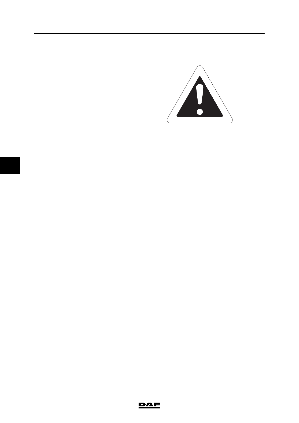
When text is accompanied by the warning symbol
shown here, the information provided is essential
for the health and safety of the mechanic.
This warning symbol is also shown if there are
circumstances in which there is a vehicle safety
hazard or damage to the vehicle could arise.
2.4 ENVIRONMENT
By carrying out the maintenance activities in a
professional manner, on time and at regular
intervals, you will help to reduce the impact on the
environment.
This means, for example, noticing and remedying
possible leakages in time and keeping the engine
in an optimum condition (adjusting valves,
replacing air filter element etc.), thus reducing the
emission of harmful exhaust gasses.
It should be noted that oils and fluids contain
harmful substances that have a negative impact
on the environment.
That is why you should take care that drained oils
and fluids and also discarded oil and fuel filters,
are collected in separate receptacles or
containers.
In short: maintenance activities must be
carried out in an environmentally aware
manner.
ΛΦ45/55 series
M0015
2-2
©
200515
Page 45
EXPLANATORY NOTES ON THE MAINTENANCE ACTIVITIES
ΛΦ45/55 series
2.5 PARTS
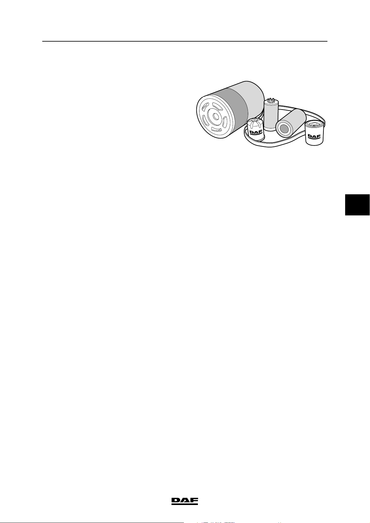
All DAF parts and components have been
carefully attuned to each other, a decisive factor
in ensuring the original DAF quality.
It is only logical, therefore, that the original DAF
quality can be maintained best if original DAF
parts and components are used when replacing
parts or components.
As far as maintenance activities are concerned,
this includes components such as windscreenwiper blades, air-dryer elements, gaskets, V-belts
and filters.
For example, if "non-original DAF filters" are
used, the engine will be insufficiently protected
against fine microscopic airborne dust particles,
almost imperceptible metal swarf in the oil and
dirt in the fuel, resulting in:
- premature replacing of cylinders, pistons,
bearings, valves, injector pump and other
moving parts
- reduced engine performance
- increased fuel consumption
General
G000183
5
Therefore, always use original DAF parts and
components.
©
200515 2-3
Page 46

EXPLANATORY NOTES ON THE MAINTENANCE ACTIVITIES
5
General
2.6 MAINTENANCE GUIDELINES
- When carrying out maintenance activities on
the vehicle, it is important that the work is
performed under the cleanest possible
conditions.
Filler caps, lubricating points, filler and drain
plugs should be cleaned before and after
maintenance activities.
- When excessive leakage has been detected
at oil seals and/or components, or in case of
excessive drops in the oil level, a report
should be made and the cause should be
remedied.
- It is important to check the gearbox
breathers, transfer box, rear axle and driven
front axle regularly for fouling and blockages.
If the breathers are blocked by dirt,
overpressure may cause leaks.
- Depending on the circumstances in which
the vehicle is used, e.g. on very bad roads or
construction sites, important bolt
connections such as the fifth wheel, spring
suspension, U-bolts, trailer coupling,
steering box attachment, superstructure
attachments etc. should be inspected more
often and, if necessary, be retightened.
ΛΦ45/55 series
- It is important that a visual inspection and
test run are carried out following the
maintenance activities.
Particular attention should be paid to
components directly related to driving safety.
- Once a service has been completed new
information on the next service (mileage/
date) can be entered on the instrument panel
display using DAVIE XD via the VIC.
2-4
©
200515
Page 47
EXPLANATORY NOTES ON THE MAINTENANCE ACTIVITIES
ΛΦ45/55 series
3. INSPECTION AND ADJUSTMENT
3.1 CHECKING PEDAL RUBBERS
1. Check that the pedal rubbers are still
securely mounted on the pedal.
2. Check that the pedal rubbers are not worn
out and there is still sufficient tread.
3.2 CHECKING THE BATTERY FLUID LEVEL
Avoid sparks and open flames in the
vicinity of batteries. Battery acid is
}
an aggressive fluid.
In the event of contact with the skin:
rinse the skin with plenty of water for
a sustained period. If redness or
pain persists, consult a doctor.
Remove any clothing affected and
rinse with water.
In the event of contact with the eyes:
rinse with plenty of water for at least
15 minutes and consult a doctor.
If swallowed: do NOT induce
vomiting. Rinse the mouth, drink two
glasses of water and consult a
doctor.
In the event of inhalation: get fresh
air, rest and consult a doctor.
Inspection and adjustment
5
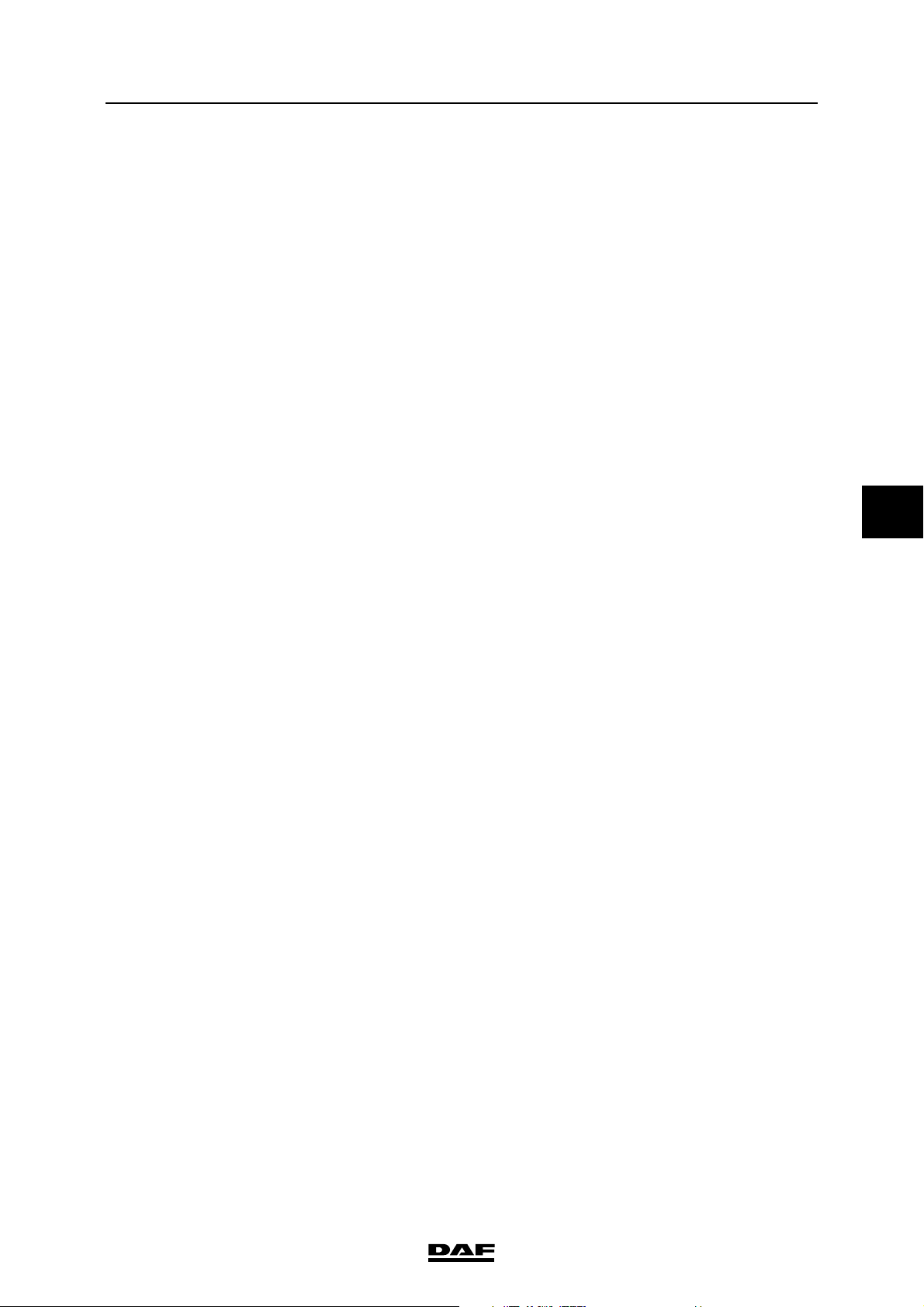
1. Check the electrolyte level. The electrolyte
level must be approx. 10 mm above the
plates or up to the level indicator if available.
2. If necessary, top up the batteries, see
chapter "Draining and filling".
©
200515 3-1
Page 48
EXPLANATORY NOTES ON THE MAINTENANCE ACTIVITIES
5
Inspection and adjustment
3.3 CHECKING THE BATTERY TERMINALS
1. Visually check the battery terminals for
corrosion. Clean the battery terminals if
necessary, see chapter "Cleaning".
2. Check the attachment of the battery
terminals.
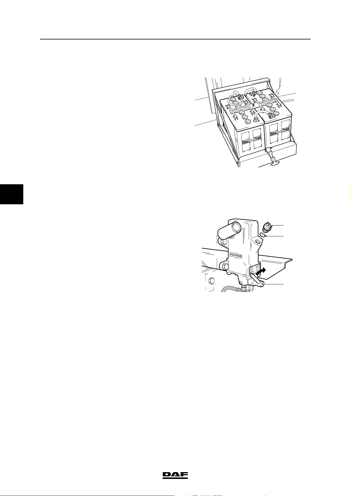
3.4 CHECKING THE FLUID LEVEL OF THE CAB TILTING PUMP
ΛΦ45/55 series
G0 00 208
1. Check the fluid level when the cab is in the
driving position.
2. The cock (3) should be in the "" position
(clockwise).
3. Loosen the filler plug (1) 3 to 4 turns and wait
until any overpressure has left the reservoir.
Then remove the filler plug (1) and check the
sealing ring (2), replace if necessary.
4. Start pumping with a maximum of five pump
strokes, making sure that the pump lever is in
the bottom position when finished.
5. Then check the fluid level. This level should
be no more than 2 cm below the top of the
filling opening. Top up if necessary.
6. Fit the filler plug (1) and hand tighten it.
1
2
3
K1 01 181
3-2
©
200515
Page 49
EXPLANATORY NOTES ON THE MAINTENANCE ACTIVITIES
ΛΦ45/55 series
Inspection and adjustment
3.5 CHECKING THE CAB FASTENING
1. Tilt the cab.
2. Check that all attachment bolts are in place.
3. Visually inspect the attachment of the cab to
the tilting mechanism.
4. Visually inspect the seals and condition of
the tilting mechanism.
Engine, cooling system and fuel system
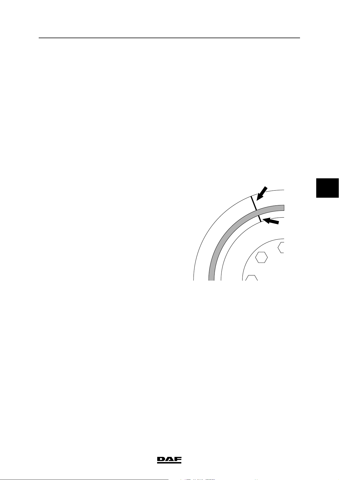
3.6 CHECKING THE VIBRATION DAMPER (VULCANISED VERSION)
OF THE BE ENGINE
1. Check that the marks on the vibration
damper are aligned. If the marks are not in
line, the vibration damper must be replaced.
5
2. Check the rubber part for damage. If the
rubber part shows cracks or there are bits of
rubber missing, the vibration damper must
be replaced.
G0 00 199
©
200515 3-3
Page 50
EXPLANATORY NOTES ON THE MAINTENANCE ACTIVITIES
5
Inspection and adjustment
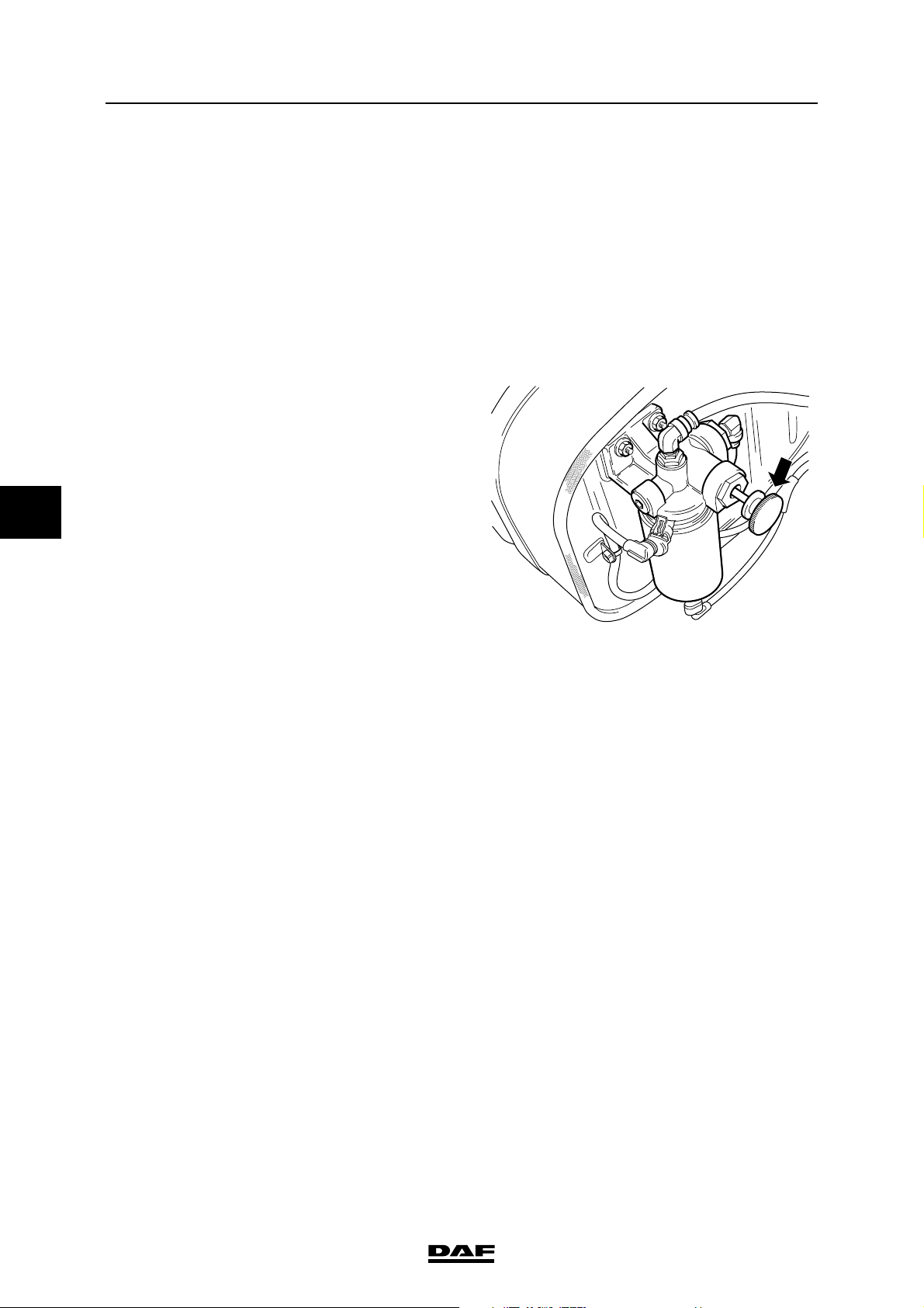
3.7 BLEEDING THE FUEL SYSTEM
Stop pumping as soon as a greater
resistance is felt. If you continue
}
Note:
When the hand pump is used, the fuel system will
be automatically bled. Air will be fed back to the
tank through the return pipe.
1. Unscrew the button of the primer pump and
2. Use the primer pump until a clearly higher
3. Press the button and tighten it.
pumping, the fuel system may
become internally damaged.
pull it out.
resistance is perceptible.
ΛΦ45/55 series
G0 00 209
3-4
©
200515
Page 51
EXPLANATORY NOTES ON THE MAINTENANCE ACTIVITIES
ΛΦ45/55 series
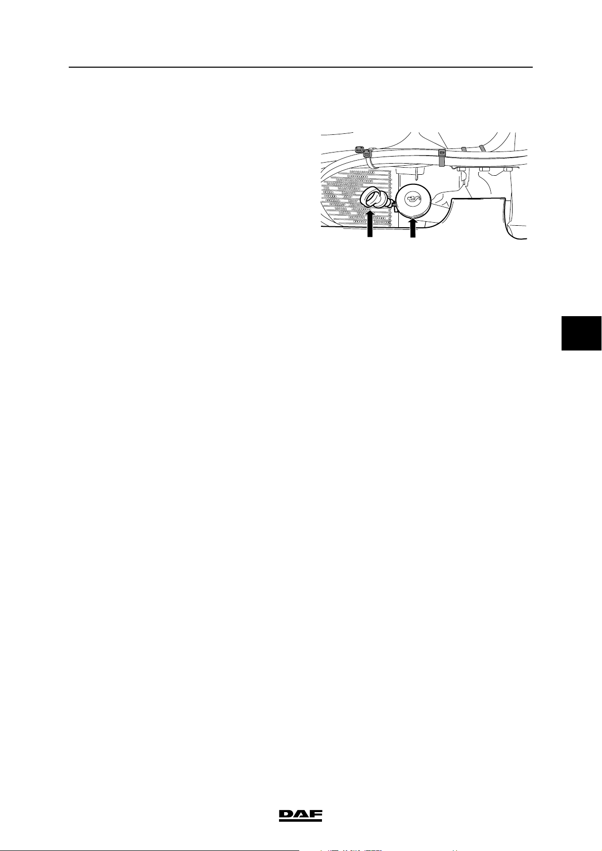
3.8 CHECKING THE ENGINE OIL LEVEL
1. Ensure that the vehicle is entirely horizontal.
2. Pull the dipstick (2) out of the holder.
3. Wipe the dipstick clean with a lint-free cloth.
4. Put the dipstick back into the holder.
5. Pull the dipstick out again and check the oil
level.
Note:
It takes approx. 20 minutes for all the oil to
run into the sump when the engine is "warm".
If the dipstick is checked immediately after
switching the engine off or immediately after
oil has been added, the level shown on the
dipstick will be too low.
6. Fill oil through the filler opening (1) until the
oil level reaches the maximum mark. See
"Draining and filling". Always use the
specified oil. Do not top up above maximum
level.
Inspection and adjustment
21
G0 00 212
5
Note:
For the difference between minimum and
maximum engine oil level, see "Technical
data".
©
200515 3-5
Page 52
EXPLANATORY NOTES ON THE MAINTENANCE ACTIVITIES
5
Inspection and adjustment
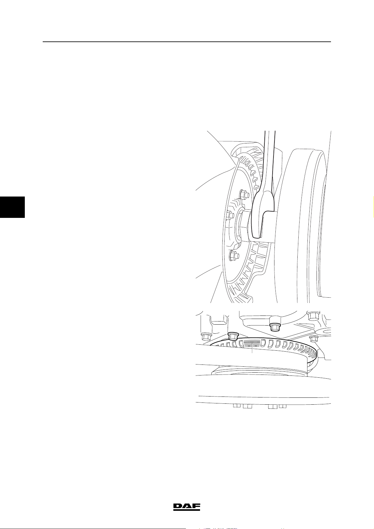
3.9 CHECKING AND ADJUSTING BE ENGINE VALVE CLEARANCE
Note:
Checking and adjusting valve clearance must
only be done when the engine is cold.
1. Remove the valve cover. See "Removing
and installing".
2. Use an open-end spanner on the fan shaft to
turn the crankshaft clockwise, as seen from
the vibration damper end (this is the engine's
normal direction of rotation), until the mark
(A) is between the bolts (B) and the valves of
cylinder 1 are in overlap position.
Note:
"Overlap" is the moment at which the inlet
valves start opening and the exhaust valves
stop closing.
The inlet valves are operated by the short
rockers and the exhaust valves by the long
rockers.
ΛΦ45/55 series
M201318
B
B
A
M201065
3-6
©
200515
Page 53
EXPLANATORY NOTES ON THE MAINTENANCE ACTIVITIES
ΛΦ45/55 series
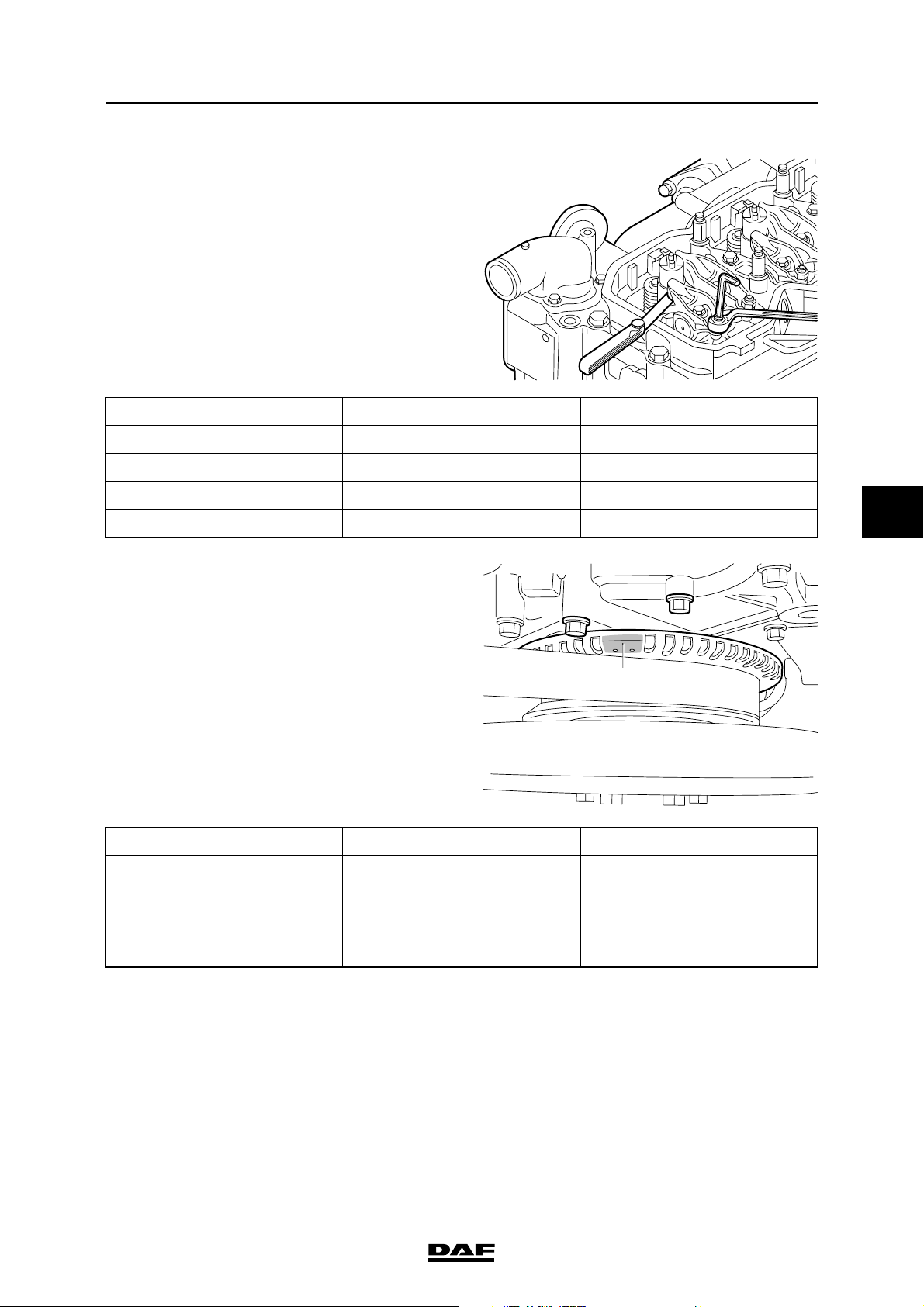
3. Check/correct the valve clearance of the
specified inlet and exhaust valves. Set the
correct valve clearance by loosening the lock
nut and rotating the adjusting screw in the
correct direction; see "Technical data" for the
correct valve clearance.
Cylinder Inlet valve Exhaust valve
1
2X
3X
4XX
4. Using an open-end spanner on the fan shaft,
turn the crankshaft one rotation further so
that the mark (A) is once again between the
bolts (B) and the valves of cylinder 4 overlap.
Inspection and adjustment
B
B
M201064
5
5. Check/correct the valve clearance of the
specified inlet and exhaust valves. Set the
correct valve clearance by loosening the lock
nut and rotating the adjusting screw in the
correct direction; see "Technical data" for the
correct valve clearance.
Cylinder Inlet valve Exhaust valve
1X X
2X
3X
4
6. Fit the valve cover. See "Removing and
installing".
7. Fit the flexible pipe, air inlet pipe and bracket.
A
M201065
©
200515 3-7
Page 54
EXPLANATORY NOTES ON THE MAINTENANCE ACTIVITIES
5
Inspection and adjustment
ΛΦ45/55 series
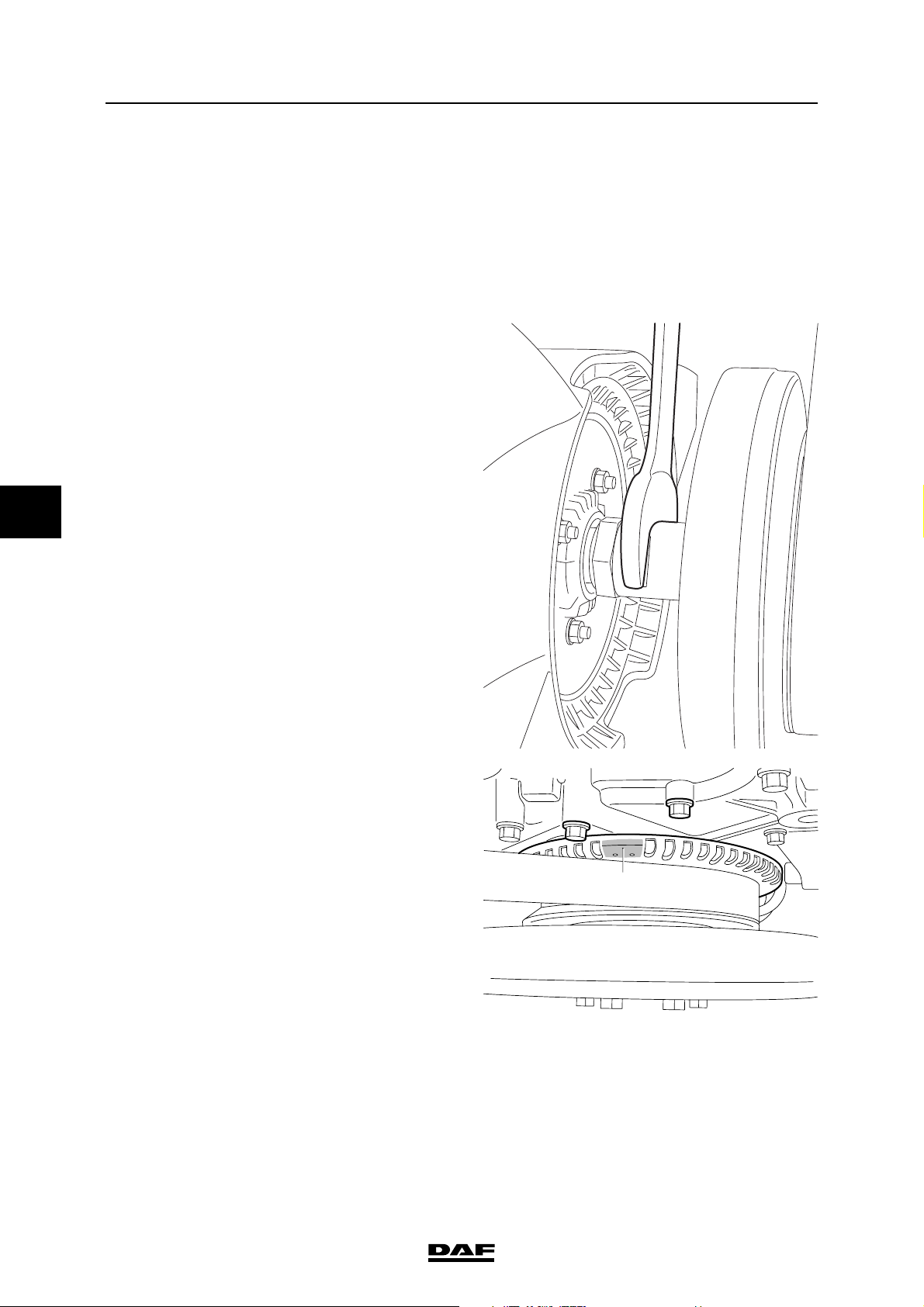
3.10 INSPECTION AND ADJUSTMENT, CE ENGINE VALVE CLEARANCE
Note:
Inspection and adjustment of valve clearance
must only be carried out when the engine is cold.
1. Remove the valve cover. See "Removal and
installation".
2. Use an open-end spanner on the fan shaft to
turn the crankshaft clockwise, as seen from
the vibration damper end (this is the engine's
normal direction of rotation), until the mark
(A) is between the bolts (B) and the valves of
cylinder 1 are in overlap position.
Note:
"Overlap" is the moment at which the inlet
valves start opening and the exhaust valves
stop closing.
The inlet valves are operated by the short
rockers and the exhaust valves by the long
rockers.
M201318
B
B
A
M201065
3-8
©
200515
Page 55
EXPLANATORY NOTES ON THE MAINTENANCE ACTIVITIES
ΛΦ45/55 series
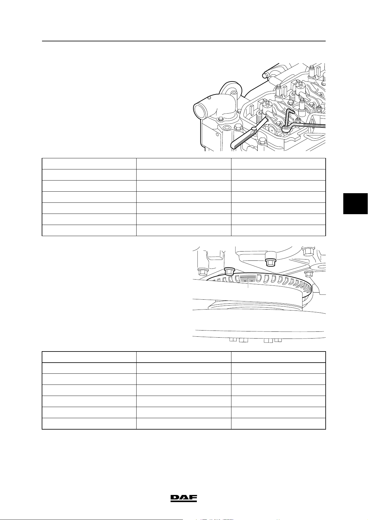
3. Check/correct the valve clearance of the
specified inlet and exhaust valves. Set the
correct valve clearance by loosening the
locknut and rotating the adjusting screw in
the correct direction; see "Technical data" for
the correct valve clearance.
Cylinder Inlet valve Exhaust valve
1
2X
3X
4X
5X
Inspection and adjustment
M201064
5
6X X
4. Using an open-end spanner on the fan shaft,
turn the crankshaft one rotation further so
that the mark (A) is once again between the
bolts (B) and the valves of cylinder 6 overlap.
5. Check/correct the valve clearance of the
specified inlet and exhaust valves. Set the
correct valve clearance by loosening the
locknut and rotating the adjusting screw in
the correct direction; see "Technical data" for
the correct valve clearance.
Cylinder Inlet valve Exhaust valve
1X X
2X
3X
4X
B
B
A
M201065
5X
6
6. Fit the valve cover. See "Removal and
installation".
©
200515 3-9
Page 56
EXPLANATORY NOTES ON THE MAINTENANCE ACTIVITIES
5
Inspection and adjustment
3.11 CHECKING THE POLY-V-BELT
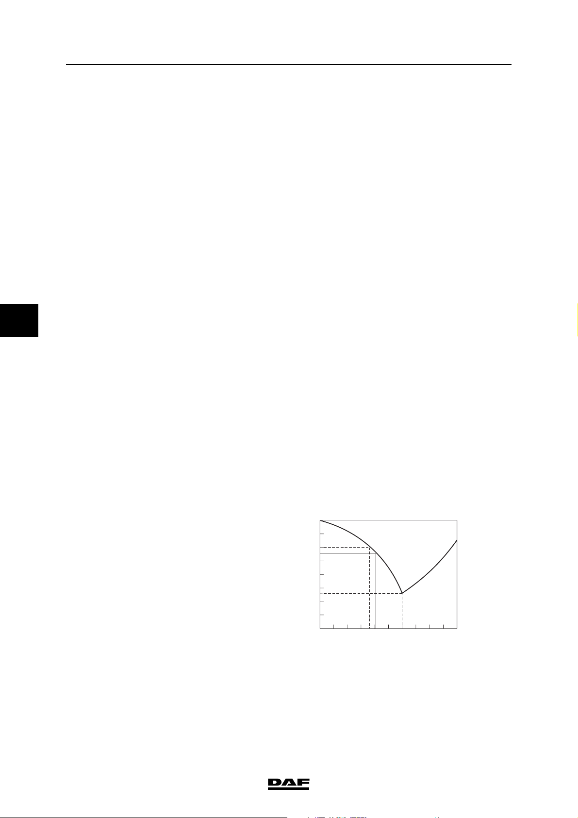
1. Check the poly-V-belt for damage and signs
of serious wear.
3.12 CHECKING THE COOLANT FREEZING POINT
When the coolant is hot, there is an
overpressure in the cooling system.
}
Carefully remove the filler cap to
release the overpressure.
Do not remove the filler cap when the
engine is running.
Coolant is a toxic fluid. Contact with
the skin should therefore be
avoided.
In the event of contact with the skin:
remove with paper or a cloth, wash
with soap and water. If irritation
persists, consult a doctor.
If swallowed: DO NOT induce
vomiting. Rinse mouth, drink two
glasses of water and consult a
doctor.
In the event of inhalation: get some
fresh air and rest.
In order to avoid damaging the
cylinder block, do not top up a warm
engine with coolant.
ΛΦ45/55 series
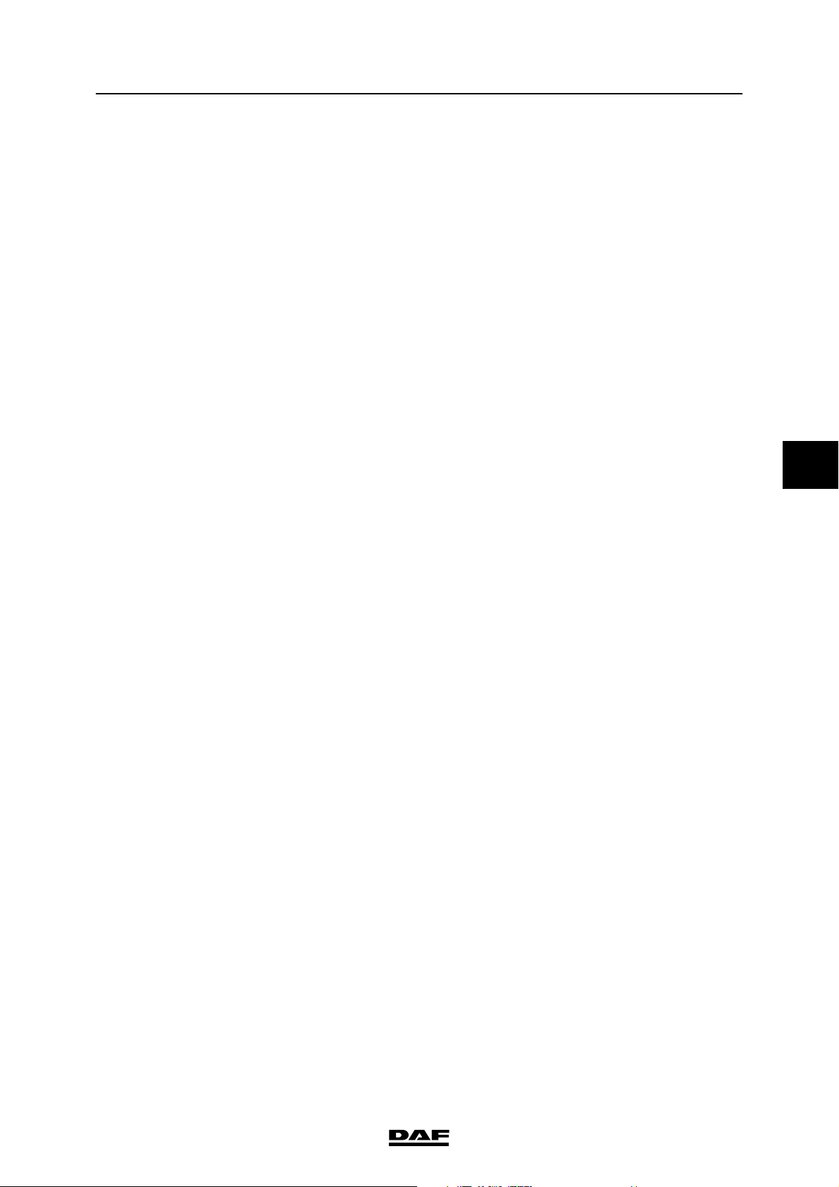
1. Check the anti-freeze content of the coolant.
Fill the cooling system with anti-freeze, if this
has not been done yet. Always use only
coolants that meet DAF specifications.
2. Consult the manufacturer’s instructions for
the correct anti-freeze mixing ratio.
Preferably, use 40% anti-freeze on an
ethylene glycol base. At this percentage, not
only good frost protection, but also good
corrosion protection is guaranteed.
o
C
0
-10
-20
-30
-40
-50
-60
-70
-80
10009010802070306040505040603070208010
Ethyleenglycol
%
90
100
H
O
0
2
M2016
3-10
©
200515
Page 57
EXPLANATORY NOTES ON THE MAINTENANCE ACTIVITIES
ΛΦ45/55 series
Inspection and adjustment
3.13 CHECKING FOR FUEL LEAKS
1. Visually inspect all hose connections and
fuel system components for leaks.
3.14 CHECKING THE COMPONENTS AND HOSE CONNECTIONS FOR LEAKS
1. Check all hose connections and cooling
system components for leaks.
2. Check the hose connections and inlet
system components.
3.15 CHECKING THE EXHAUST SYSTEM
1. Visually inspect the exhaust system for
leaks.
5
2. Check the exhaust suspension points.
3. Check that no heat transfer (due to
accumulated dirt, for example) can take
place to the exhaust system area, such as
pipes, components etc.
3.16 CHECKING THE RADIATOR AND INTERCOOLER FOR FOULING
1. Visually inspect the radiator and intercooler
for fouling If necessary, clean the radiator
and intercooler, see "Cleaning".
©
200515 3-11
Page 58
EXPLANATORY NOTES ON THE MAINTENANCE ACTIVITIES
5
Inspection and adjustment
3.17 CHECK THE AIR INLET DUST TRAPPING VALVE
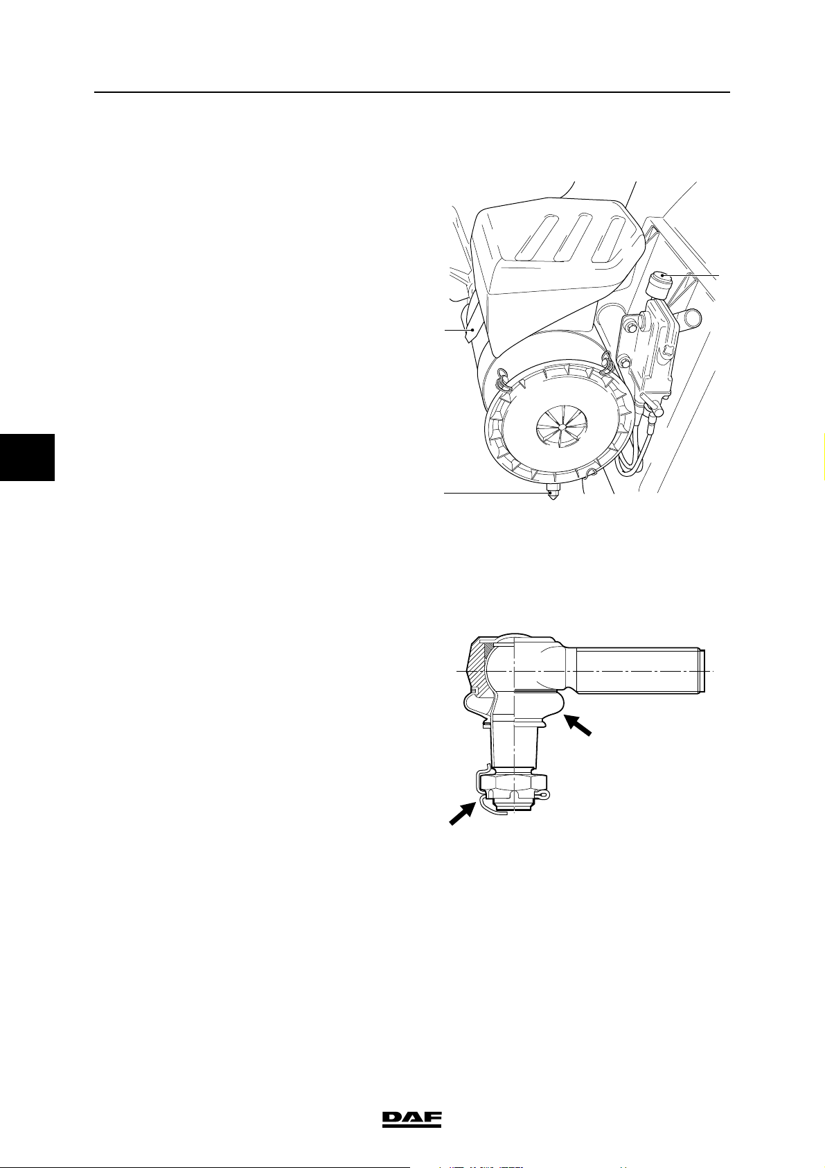
1. Check the rubber sealing valve (1) at the
bottom of the filter housing for clogging and
damage.
Steering gear and brake s ystem
2
1
ΛΦ45/55 series
3
I4 00 535
3.18 CHECKING THE STEERING BALL JOINT SLEEVE FOR DAMAGE
Inspection, locking devices and dust cover
1. Check that the steering ball joint dust cover
or seal is not damaged. Replace the steering
ball joint if damaged.
2. If a castle nut is fitted, check that the locking
devices are present and undamaged.
S7 00 592
3-12
©
200515
Page 59

EXPLANATORY NOTES ON THE MAINTENANCE ACTIVITIES
ΛΦ45/55 series
3.19 CHECKING THE STEERING BALL JOINTS
Checking axial steering ball joint play
1. Check the axial steering-ball joint play using
special tool (DAF no. 1329426)
2. First jack up the axle until the wheels come
off the ground and put the axle on stands.
3. Make sure that the castle nut split pin (if
fitted) at the nut does not come into contact
with the head of the threaded end.
4. Screw the thrust washer (8) on to the
threaded spindle.
5. Fit the spring retainer (3), spring (4) and
pressure sleeve (6) into bracket (1). Fit the
locking screw (5). It should be possible to
move the pressure sleeve (6) freely.
Note:
Fit the correct pressure sleeve (6).
The pressure sleeve (6) must abut the outer
edge of the steering ball joint (7).
6. Loosen thrust bolt (2) until the pressure
sleeve (6) with the flange abuts the bracket
(A = 0 mm).
7. Fit the special tool over the steering ball joint
(7) and turn the threaded spindle (9) by hand
until the special tool is tight around the
steering ball joint (7).
8. Tighten thrust bolt (2) until its head abuts
bracket (1).
A
Inspection and adjustment
9
8
7
6
5
4
3
2
5
1
S700426
9. Measure play "A" between the pressure
sleeve and the bracket using a feeler gauge.
Compare the reading with the maximum
permissible steering ball joint play, see
"Technical data".
If necessary, replace the steering ball joint.
©
200515 3-13
Page 60
EXPLANATORY NOTES ON THE MAINTENANCE ACTIVITIES
5
Inspection and adjustment
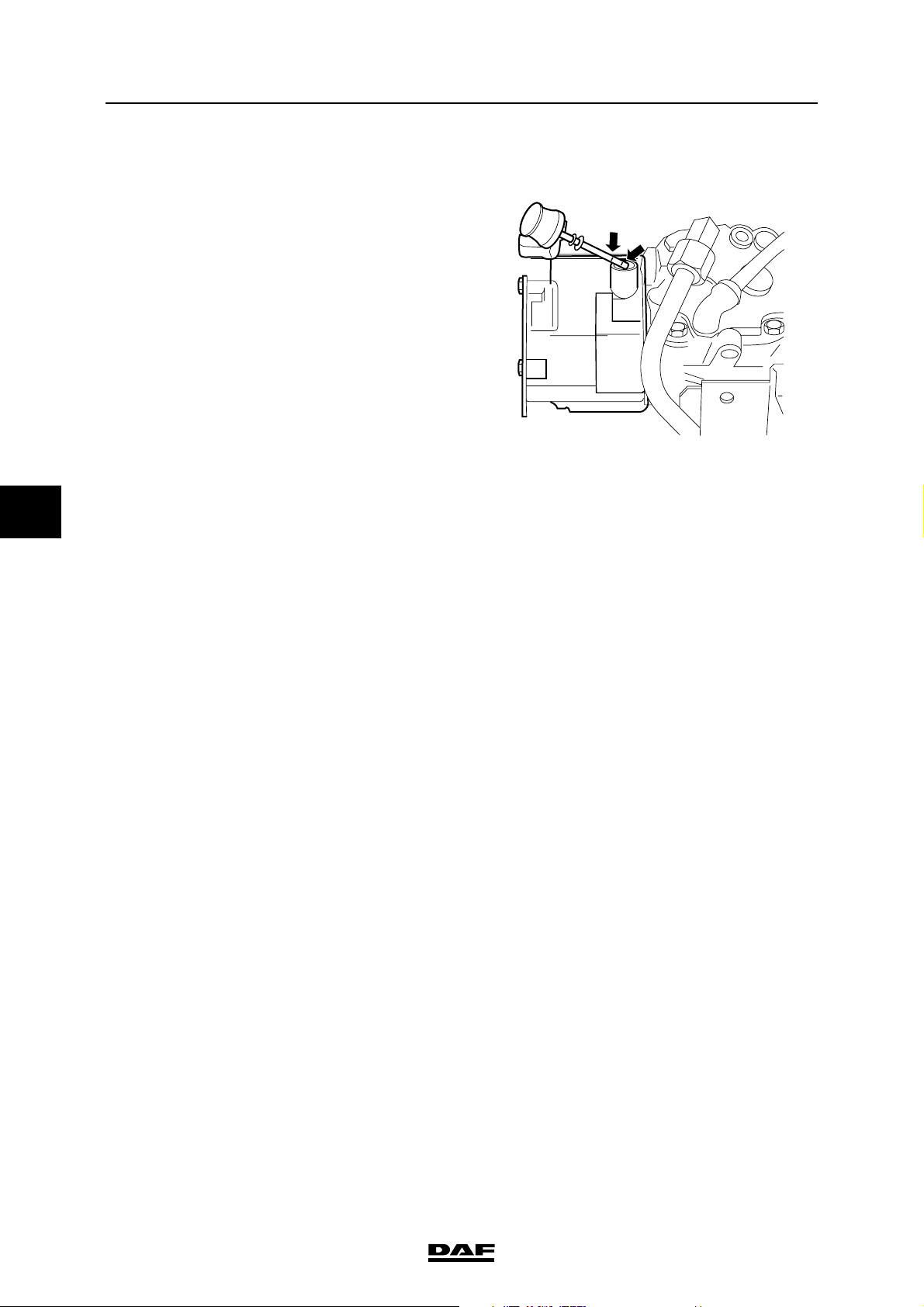
3.20 CHECKING THE STEERING OIL LEVEL
1. Check the steering oil level when the engine
is not running.
2. Tilt the cab.
3. Clean the dipstick and its surroundings so
that absolutely no dirt can get into the
reservoir.
4. Check the fluid level in the reservoir using
the dipstick.
5. The fluid level should be between the marks
when the steering oil is "cold".
Note:
When the steering oil is at operating
temperature, the level may be above the top
mark.
ΛΦ45/55 series
G0 00 214
3-14
©
200515
Page 61
EXPLANATORY NOTES ON THE MAINTENANCE ACTIVITIES
ΛΦ45/55 series
Inspection and adjustment
3.21 CHECKING THE STEERING GEAR LINES AND CONNECTIONS
1. Condition of the pipes
- Check all pipes for tightness and wear.
Where supply pipes are subject to
negative pressure, it is particularly likely
that porous pipes will give rise to
problems (air in the system).
- If in doubt, always replace the line.
2. Pipe connections
- Check every pipe connection for leaks.
3. Line route
- Pipes must not be twisted during
assembly. To facilitate checking this,
a mark may have been provided on the
hose (sometimes in the form of text).
- Pipes should not touch other parts (to
prevent chafing).
- The course pipes follow should not
include any sharp bends; this applies
especially to the flexible suction and
return pipes.
- Pipes should not be pinched off by other
components.
5
©
200515 3-15
Page 62

EXPLANATORY NOTES ON THE MAINTENANCE ACTIVITIES
5
Inspection and adjustment
ΛΦ45/55 series
3.22 CHECKING THE BRAKE COMPONENTS AND BRAKE SYSTEM FOR LEAKS
1. While operating the service brake, check
whether any leaks occur in the brake system.
If the brake system of a vehicle has been
charged to the maximum pressure, it should
generally be possible to drive the vehicle
after a period of 16 hours of uninterrupted
standstill, without having to first charge the
brake system to adequate operating
pressure. This implies a maximum pressure
drop of approx. 0.4 bar per hour at normal
system pressure.
Note:
Always connect auxiliary consumers and
accessories to circuit 4.
3.23 CHECKING THE BRAKE CYLINDER FASTENING
1. Check that the brake cylinders do not move
during operation of the service brake.
3-16
©
200515
Page 63
EXPLANATORY NOTES ON THE MAINTENANCE ACTIVITIES
ΛΦ45/55 series
Inspection and adjustment
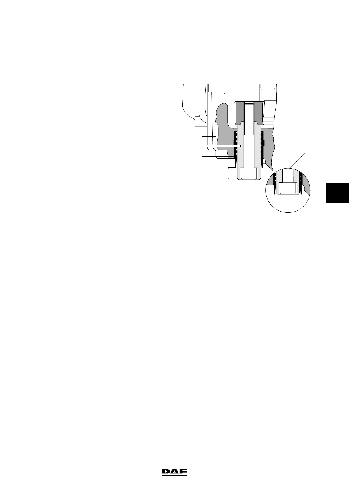
3.24 CHECKING THE BRAKE PAD THICKNESS AND BRAKE DISC
Version: Knorr SB 7000
1. Check whether guide bush (4) protrudes
from guide sleeve (6) (C).
If the guide bush (4) is level with the guide
sleeve (6) (see detail A) the brake pad and
brake disc thicknesses should be checked.
1
4
6
C
A
5
R600481
©
200515 3-17
Page 64
EXPLANATORY NOTES ON THE MAINTENANCE ACTIVITIES
5
Inspection and adjustment
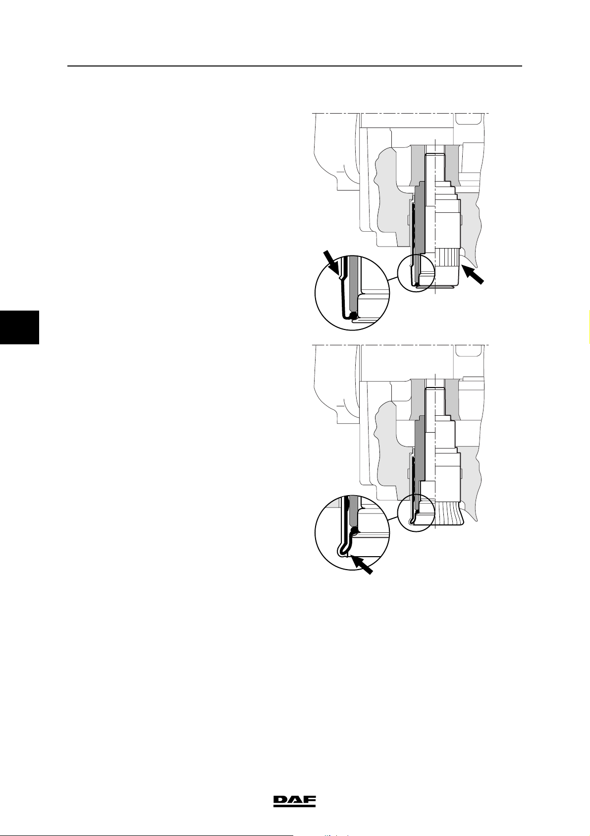
Version: Knorr SN 7000
1. Check the transition between the ribbed part
of the rubber cover and the smooth part (A).
If the smooth part is rolled inwards, the brake
pad and brake disc thicknesses must be
checked.
Version: Wabco
1. There is no wear indicator in this version.
The brake pad thickness must be inspected
by using a mirror and a lamp, if necessary.
ΛΦ45/55 series
A
A
3-18
A
R600730
©
200515
Page 65

EXPLANATORY NOTES ON THE MAINTENANCE ACTIVITIES
ΛΦ45/55 series
Inspection and adjustment
3.25 INSPECTION AND ADJUSTMENT, LOAD SENSING VALVE, AIR
SUSPENSION
Explanatory notes on instruction plate
The information contained on the plate relates to
the axle loads, the output pressures and bellows
pressures, in accordance with the order of axles
beneath the vehicle.
"1" refers to the (first) front axle, "2" to the
following axle, etc.
In the entire column, a reading of 6 bar has been
filled in under "1".
If the vehicle is equipped with an empty/load
valve, a pressure ratio is entered in the box under
the valve illustration, e.g. "i = 1 : 1.5".
The "delivery pressure p2" of axle "1" then
indicates variable readings.
These values can be used to check the brake
pressure values of the front axle and to carry out
the inspection/adjustment below at the same
time. To do this, connect a pressure gauge to the
test connection of one of the front axle brake
cylinders.
R6 00 548
5
Inspection/adjustment
1. Check that the correct valve has been fitted
(see instruction plate).
2. Connect pressure gauge (4) to the test
connection close to connecting point 1/4 on
the load sensing valve (input pressure).
3. Connect pressure gauge (2) to the test
connection on one of the brake cylinders
(service brake connection) of the rear axle.
4. Connect a pressure gauge (43) with a
pressure-reducing valve to the simulation
connection near connections 41 and 42 of
the load sensing valve (= simulated
adjustable bellows pressure).
5. Make sure that the reservoir pressure is
higher than 6.5 bar throughout the testing
process.
6. Set the simulated bellows pressure to its
second lowest value, as indicated on the
instruction plate.
7. Depress the brake pedal until the pressure
gauge (4) indicates a pressure of 6 bar.
41
43
s
r
42
4
1/4
1
2
2
R600473
©
200515 3-19
Page 66
EXPLANATORY NOTES ON THE MAINTENANCE ACTIVITIES
5
Inspection and adjustment
8. Read the brake pressure of the rear axle on
pressure gauge 2 and check that this brake
pressure matches the one listed on the
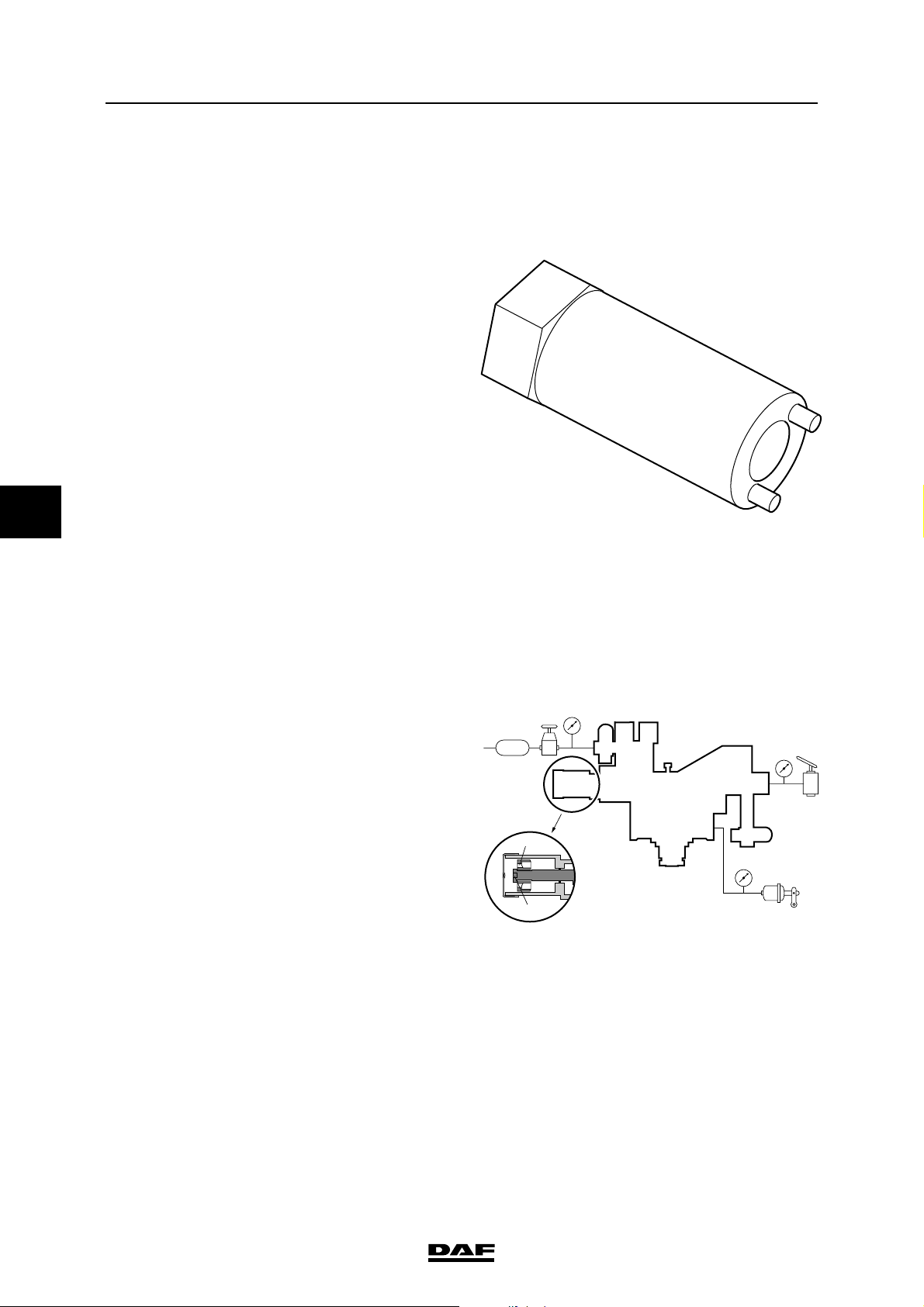
instruction plate in the table under "output
pressure p2" to the rear axle.
9. If the measured value is not correct,
depressurise connection (43) and, using a
special slotted-nut spanner, special tool
(DAF no. 1329464), turn the adjusting
nut (s):
- brake pressure too high: unscrew the
adjusting nut
- brake pressure too low: screw in the
adjusting nut
Note:
When depressurising the simulation
connection (pressure gauge 43), the air hose
must remain connected to prevent the
(actual) bellows pressure from accidentally
activating the valve.
The small socket head screw in the centre of
the valve must not be adjusted.
ΛΦ45/55 series
R600478
10. Repeat the procedure described in point 6
until the measured brake pressure value is
within the tolerance limits.
11. Set the simulated bellows pressure to its
second highest value, as indicated on the
instruction plate.
12. Depress the brake pedal until the pressure
gauge (4) indicates a pressure of 6 bar.
13. Read pressure gauge (2) and check that this
brake pressure matches the pressure
indicated in the table on the instruction plate.
14. If the measured reading is not correct,
depressurise connection (43) and turn
adjusting bolt (r) using a Torx screwdriver:
- brake pressure too high: screw in the
adjusting bolt
- brake pressure too low: unscrew the
adjusting bolt
Note:
When depressurising the simulation
connection (pressure gauge 43), the air hose
must remain connected to prevent the
(actual) bellows pressure from accidentally
activating the valve.
The small socket head screw in the centre of
the valve must not be adjusted.
41
43
s
42
4
1/4
1
2
2
r
R600473
15. If the adjusting bolt (r) has been turned,
repeat the procedure from point 6.
3-20
©
200515
Page 67
EXPLANATORY NOTES ON THE MAINTENANCE ACTIVITIES
ΛΦ45/55 series
Inspection and adjustment
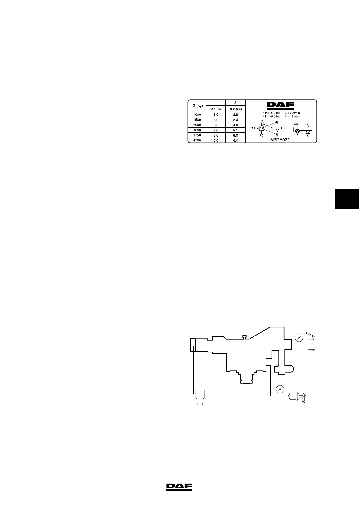
3.26 INSPECTION AND ADJUSTMENT, LOAD SENSING VALVE, LEAF
SUSPENSION
Explanatory notes on instruction plate
The data relating to axle loads and output
pressures are listed on the instruction plate
following the sequence of the axles beneath the
vehicle.
"1" refers to the (first) front axle, "2" to the
following axle, etc.
In the entire column, a reading of 6 bar has been
filled in under "1". If the vehicle is equipped with
an empty/load valve, a pressure ratio is entered
in the box under the valve illustration, e.g. "i = 1 :
1,5". The "output pressure P2" of axle 1 will give
variable readings.
These values can be used to check the brake
pressure values of the front axle and to carry out
the inspection/adjustment below at the same
time. To do this, connect a pressure gauge to the
test connection of one of the front axle brake
cylinders.
R6 00 549
5
Inspection/adjustment
1. Measure the weight plus load of the rear
axle.
2. Check the attachment of the control lever
and its ease of operation.
3. Check that the right type of valve has been
fitted.
4. Check the length of the control lever
(see "L" on the instruction plate).
5. Connect a pressure gauge (4) to the test
connection near connection 1/4 on the load
sensing valve (input pressure).
6. Connect pressure gauge (2) to the test
connection on one of the brake cylinders
(service brake connection) of the rear axle.
7. Make sure that the reservoir pressure is
higher than 6.5 bar throughout the testing
process.
8. Depress the brake pedal until pressure
gauge (4) indicates a value of 6 bar.
4
1/4
1
2
2
R600562
9. Read the brake pressure of the rear axle
from pressure gauge 2 and check that this
value matches the one listed on the
instruction plate in the table under "output
pressure p2" to the rear axle.
©
200515 3-21
Page 68
EXPLANATORY NOTES ON THE MAINTENANCE ACTIVITIES
5
Inspection and adjustment
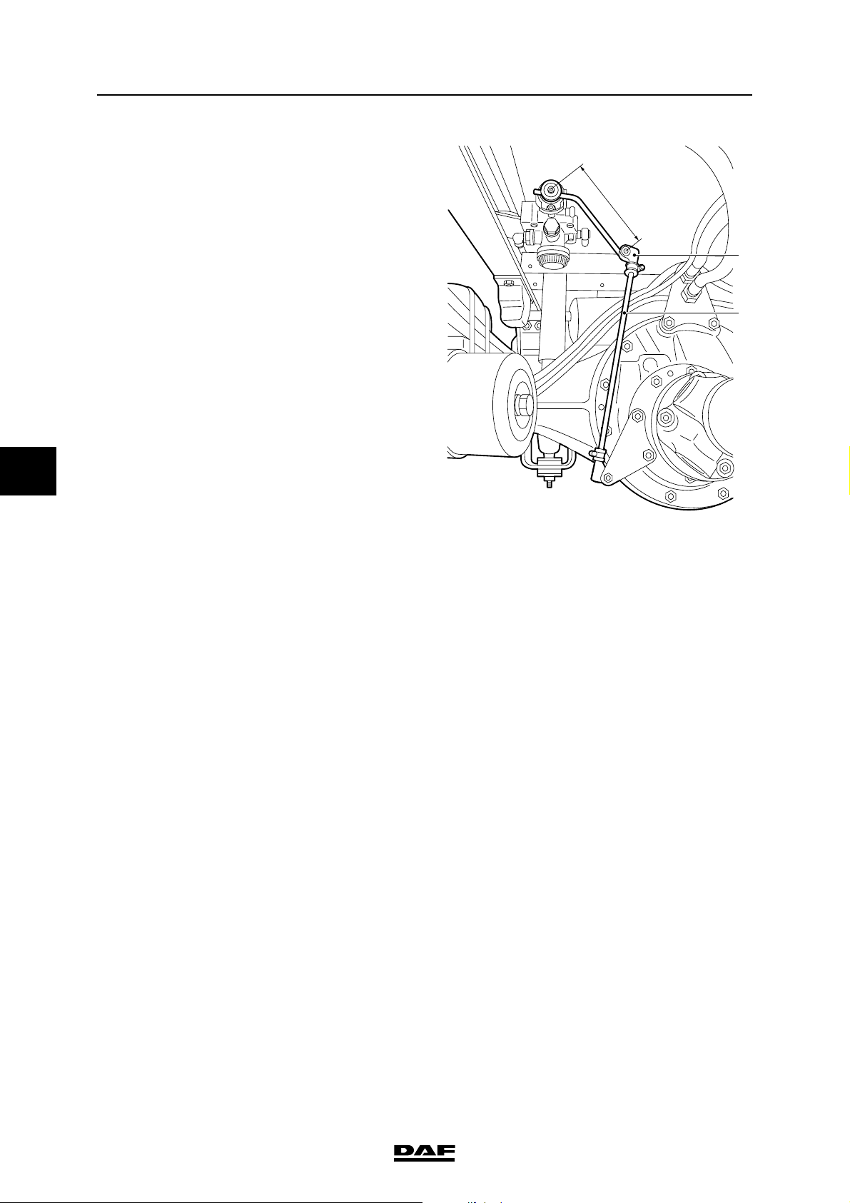
10. If necessary, correct the brake pressure by
adjusting the length of the vertical
connecting rod (2). Never attempt to alter the
length L of the (horizontal) control lever.
11. Remove the ball coupling (1) and raise the
control lever. Check that the output pressure
is now allowed through (almost) without
reduction.
Note:
The small socket head screw in the centre of
the valve must not be adjusted.
Drive and chassis
ΛΦ45/55 series
L
1
2
R6 00 568
3-22
©
200515
Page 69
EXPLANATORY NOTES ON THE MAINTENANCE ACTIVITIES
ΛΦ45/55 series
Inspection and adjustment
3.27 CHECKING THE DIFFERENTIAL FOR LEAKS
1. Visually inspect the differential for leaks.
3.28 CHECKING THE OPERATION OF THE DIFFERENTIAL LOCK
1. Jack up the rear axle and support the axle on
stands.
2. Bring the air system to operating pressure.
3. Engage the differential lock. The warning
indicator should now be active.
4. Check that there is a "rigid" connection
between the driven wheels.
5. Disengage the differential lock. The warning
light should now go out and the "rigid"
connection between the driven wheels
should be broken.
5
©
200515 3-23
Page 70
EXPLANATORY NOTES ON THE MAINTENANCE ACTIVITIES
5
Inspection and adjustment
3.29 CHECK THE DRIVE SHAFT PLAY
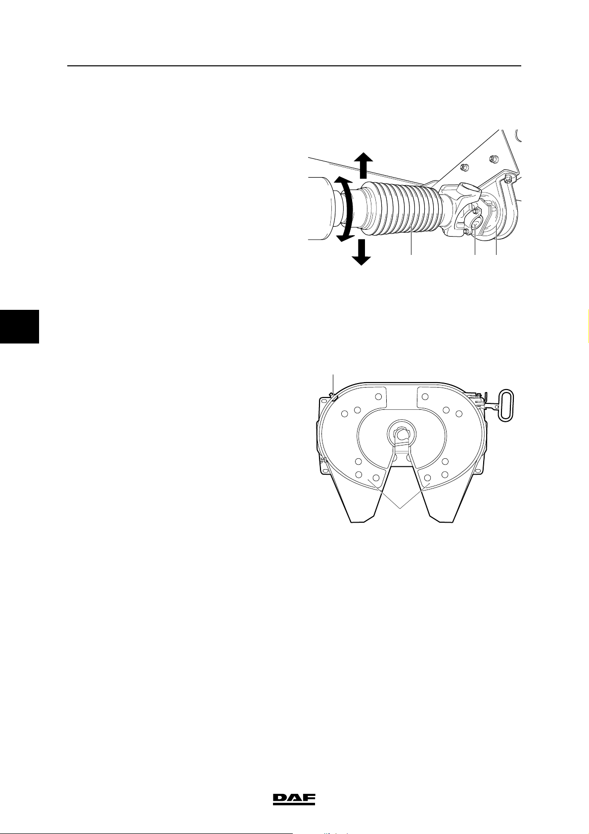
1. Check the universal joints (2) and
suspension bearing (3) for play and damage.
2. Check the sliding joint for axial and radial
play. The rubber dust cover (1) over the
sliding joint should be undamaged.
3. There must be no clearly perceptible play on
the universal joints, suspension bearing and
the sliding joint.
3.30 INSPECTING THE FIFTH WHEEL
1. Check the attachment of the fifth wheel.
2. Check the play of the closing gear of the fifth
wheel.
ΛΦ45/55 series
123
V3 00 379
2
Note:
For maximum play values, consult the
manufacturer's instructions or the legal
requirements.
3. In the case of fifth wheels with a plastic
sliding plate (1), check for wear. The plastic
sliding plate (1) must not lie flush with the top
of the attachment bolts.
1
V300372
3-24
©
200515
Page 71
EXPLANATORY NOTES ON THE MAINTENANCE ACTIVITIES
ΛΦ45/55 series
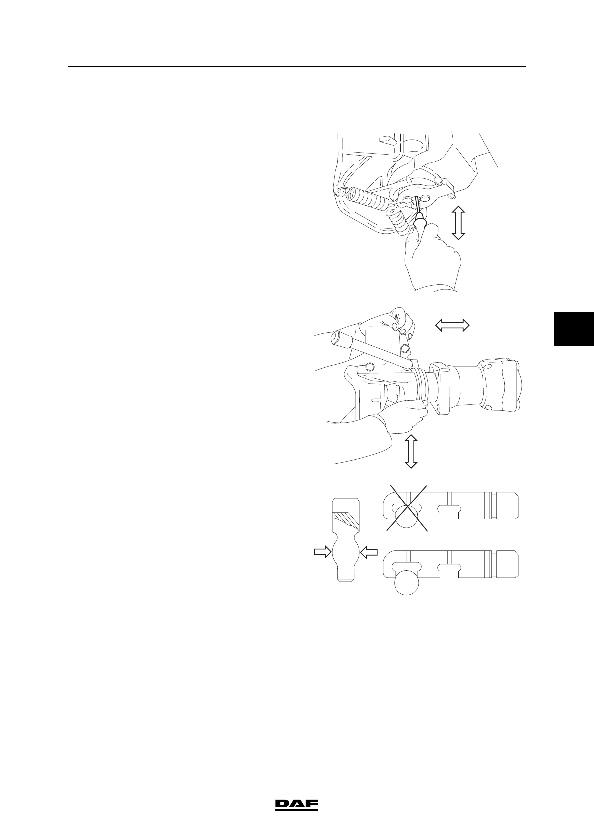
3.31 CHECKING THE TRAILER COUPLING
1. Check the vertical play of the arched pin.
2. Check the radial play of the arched pin.
3. Check the vertical and horizontal play of the
coupling jaw.
Inspection and adjustment
M9002
5
4. Check the diameter of the arched pin.
5. Check the attachment of the trailer coupling
and the rear cross member.
Note:
For maximum play values, consult the
manufacturer’s instructions or the specified
legal requirements.
M9001
M9004
©
200515 3-25
Page 72

EXPLANATORY NOTES ON THE MAINTENANCE ACTIVITIES
5
Inspection and adjustment
3.32 CHECK THE SUPERSTRUCTURE ATTACHMENT
1. Check that all attachment bolts are in place.
2. Visually check the attachment of the
superstructure for faults. See the DAF
superstructure instructions.
ΛΦ45/55 series
3-26
©
200515
Page 73
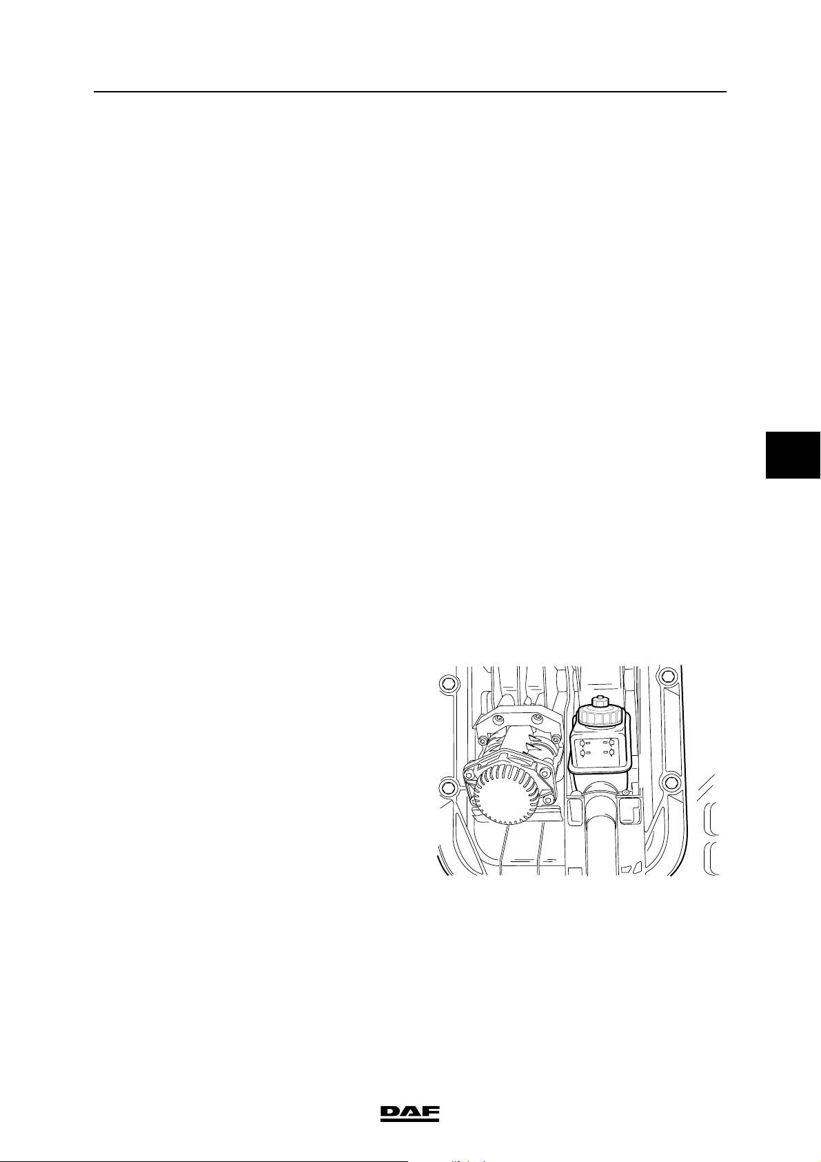
EXPLANATORY NOTES ON THE MAINTENANCE ACTIVITIES
ΛΦ45/55 series
3.33 CHECK THE CLUTCH FLUID LEVEL
Hydraulic fluid is toxic and can
therefore have a damaging effect on
}
your health.
Hence avoid any direct or indirect
physical contact.
In the event of contact with the skin:
remove the liquid with paper or a
cloth, wash with soap and water. If
irritation persists, consult a doctor.
If swallowed: DO NOT induce
vomiting. Rinse mouth, drink two
glasses of water and consult a
doctor.
In the event of inhalation: get fresh
air and rest.
As hydraulic fluid is also a corrosive
fluid, it may damage the paintwork of
the vehicle. Avoid any contact
between hydraulic fluid and
paintwork.
Always use new and clean hydraulic
fluid which has been kept in a sealed
container and meets the
specifications.
Hydraulic fluid which has absorbed
water (from the ambient air) may
have an adverse effect on the
operation of the clutch system.
Avoid any contact with mineral oil.
Even one drop of mineral oil in the
system will damage the seals.
Inspection and adjustment
5
1. Check whether the fluid level is between the
min and max marks when the cab is in the
driving position.
MAXI
MINI
P MAX 4 BAR
G0 00 213
©
200515 3-27
Page 74
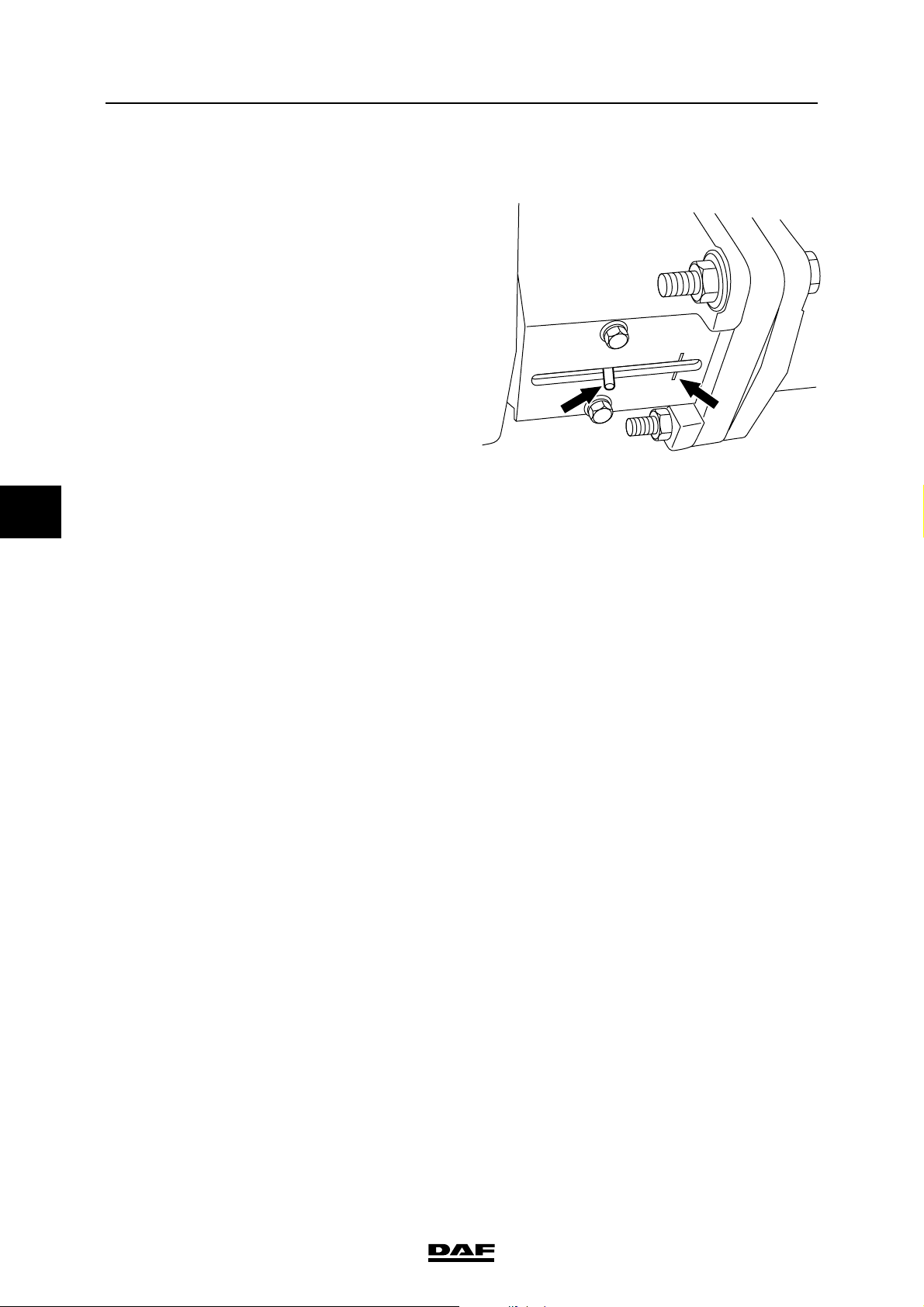
EXPLANATORY NOTES ON THE MAINTENANCE ACTIVITIES
5
Inspection and adjustment
3.34 CHECK THE CLUTCH WEAR INDICATOR
1. Check that the wear indicator on the clutch
servo has not gone past the mark on the
clutch servo plate.
2. If the wear indicator is at the mark on the
clutch servo, replace the clutch plate.
3.35 CHECKING THE GEARBOX FOR LEAKS
ΛΦ45/55 series
V3 00 374
1. Visually check the gearbox for leaks.
3-28
©
200515
Page 75
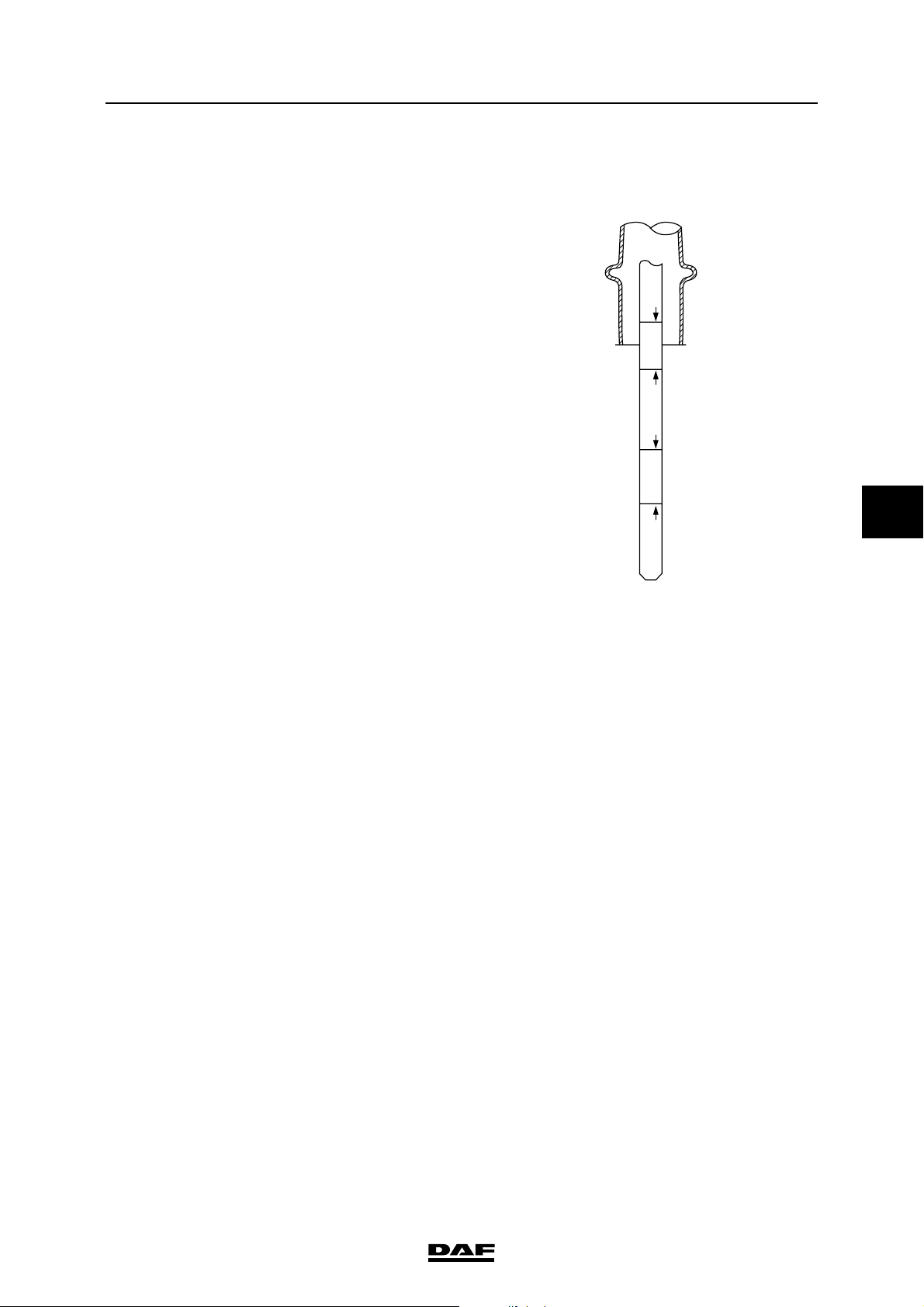
EXPLANATORY NOTES ON THE MAINTENANCE ACTIVITIES
ΛΦ45/55 series
3.36 CHECKING AUTOMATIC GEARBOX OIL LEVEL
Checking cold oil level
1. Place the vehicle on a flat and level surface.
2. Make sure that the gearbox is in neutral and
allow the engine to run for several minutes.
3. Apply the service brake, switch the gearbox
to D, then to N and finally switch the gearbox
to R. The purpose of this is to fill the hydraulic
system.
4. Switch the gearbox to the parking position
and release the service brake.
5. Remove the dipstick when the engine is
idling and wipe it clean with a lint-free cloth.
Note:
To take the dipstick out of the holder, the
sealing cap must be held while the dipstick is
turned anti-clockwise.
Inspection and adjustment
HOT
FULL
HOT
ADD
FULL
COLD
ADD
COLD
5
6. Put the dipstick back.
7. Remove the dipstick and check the oil level.
The oil level should be between the "Cold
add" and "Cold full" marks.
8. Clean the dipstick with a lint-free cloth and
put it back.
9. Remove the dipstick and check the oil level
again.
10. Oil needs to be added when the oil level is
below the "Cold add" mark.
11. Check the oil level in the gearbox at
operating temperature.
W 3 03 099
©
200515 3-29
Page 76
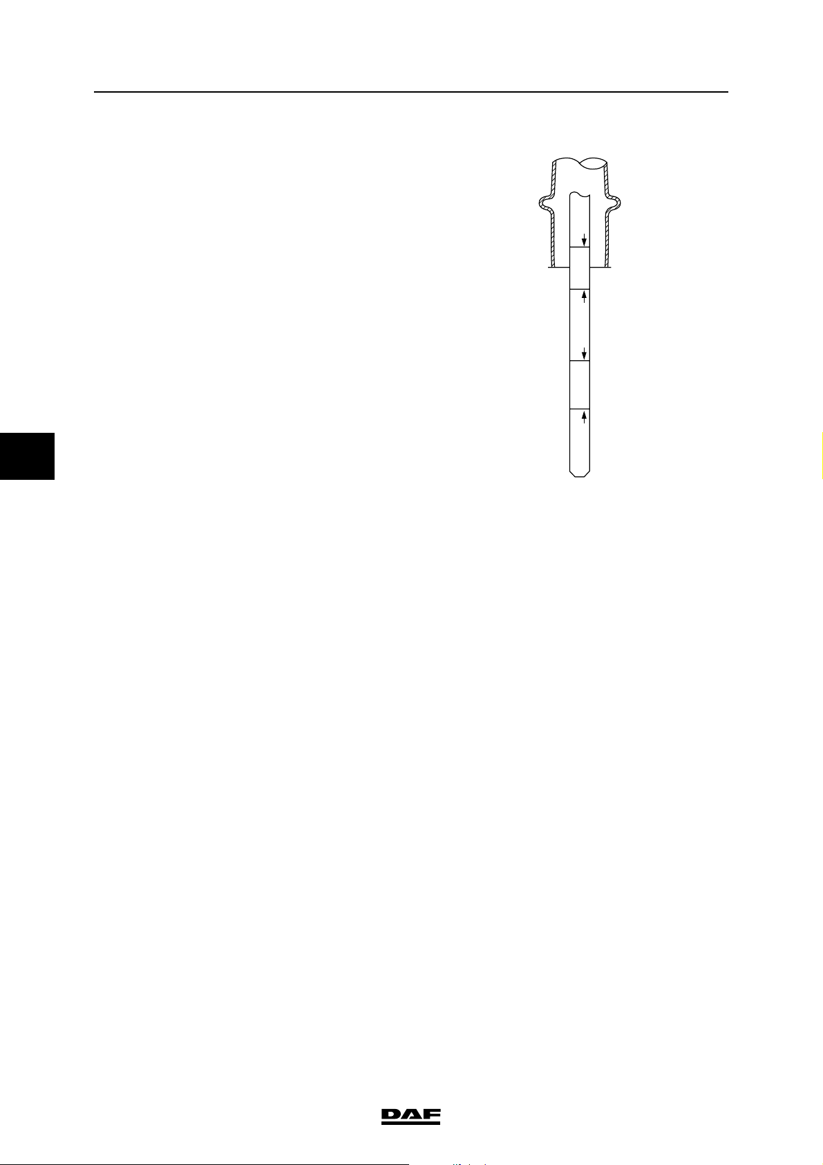
EXPLANATORY NOTES ON THE MAINTENANCE ACTIVITIES
5
Inspection and adjustment
Checking hot oil level
1. Bring the gearbox up to operating
temperature (approx. 71C - 93C).
2. Remove the dipstick when the engine is
idling and wipe it clean with a lint-free cloth.
Note:
To take the dipstick out of the holder, the
sealing cap must be held while the dipstick is
turned anti-clockwise.
3. Put the dipstick back.
4. Remove the dipstick and check the oil level.
5. The oil level should be between the "Hot
add" and "Hot full" marks.
6. Clean the dipstick with a lint-free cloth and
put it back.
7. Remove the dipstick and check the oil level
again.
HOT
FULL
HOT
ADD
FULL
COLD
ADD
COLD
W 3 03 099
ΛΦ45/55 series
8. Oil needs to be added when the oil level is
below the "Hot add" mark.
9. Oil needs to be drained when the oil level is
above the "Hot full" mark.
Note:
The oil level must be checked at least twice.
When there are differences between the
measurements, check the bleeder for
clogging.
3-30
©
200515
Page 77
EXPLANATORY NOTES ON THE MAINTENANCE ACTIVITIES
ΛΦ45/55 series
Inspection and adjustment
3.37 INSPECTION OF OIL LUBRICATED WHEEL HUBS FOR LEAKS
1. Check the wheel hubs for leaks.
Note:
If leaks occur in the oil lubricated wheel hubs,
the wheel hub should be refilled to the
correct level - once the leak has been
repaired, see chapter: "Draining and filling".
5
©
200515 3-31
Page 78
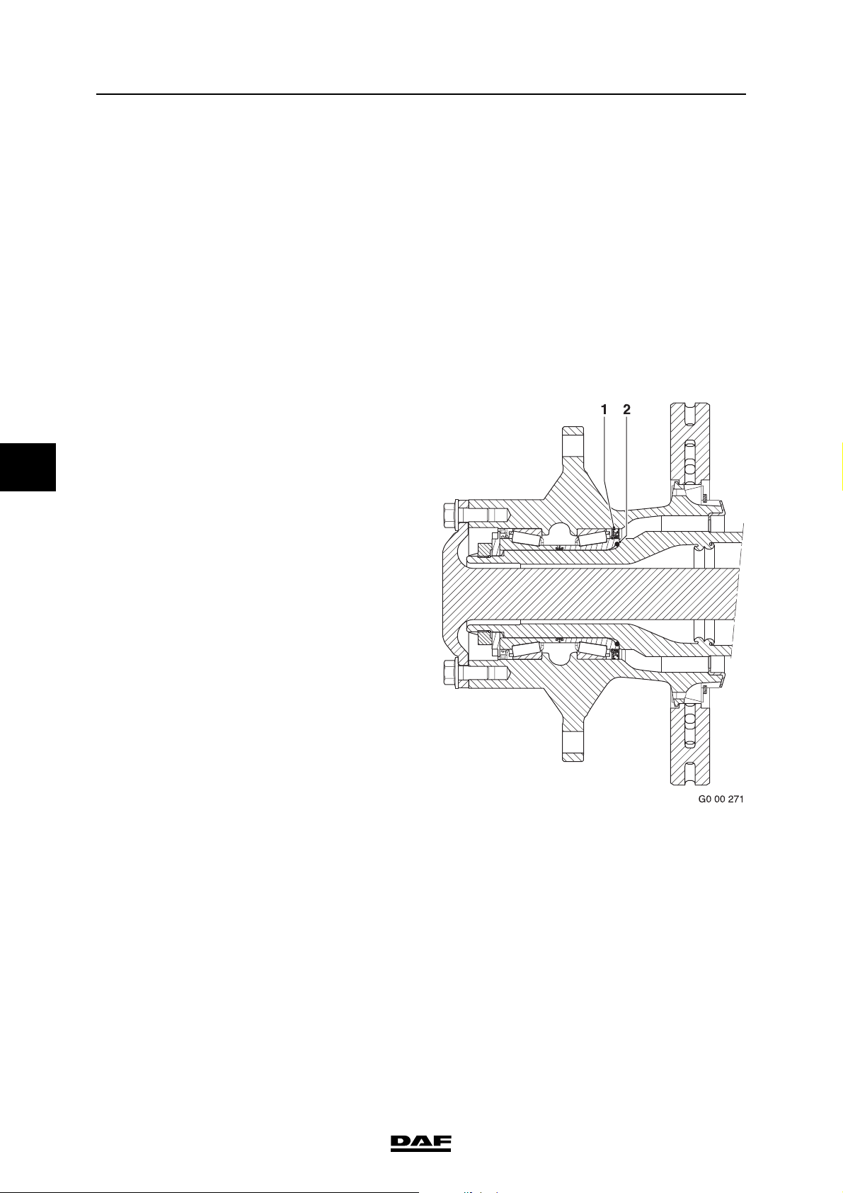
EXPLANATORY NOTES ON THE MAINTENANCE ACTIVITIES
5
Inspection and adjustment
3.38 CHECKING GREASED WHEEL HUBS FOR LEAKS
1. Check the wheel hubs for leaks.
Note:
For maintenance-free wheel hubs:
If there are serious grease marks on the
brake disc side of the wheel hub, this could
indicate excessive use of assembly grease
on new or recently assembled wheel hubs.
On wheel hubs that were not assembled
recently, serious grease marks could
indicate a leak in the seal.
Checking greased wheel hubs for leaks,
1132 axle
1. Check the wheel hubs for leaks.
Note:
If there are serious grease marks on the
brake disc side of the wheel hub, this could
indicate excessive use of assembly grease
on new or recently assembled wheel hubs.
On wheel hubs that have not been
assembled recently, serious grease marks
could indicate a leak in the seal (1). This
means that the entire hub unit must be
replaced.
Serious oil leakage on the driven rear axle
hubs could indicate that the O-ring (2) is not
sealing correctly.
If there is an oil leak the hub unit should be
dismantled to remedy the problem.
ΛΦ45/55 series
3-32
©
200515
Page 79
EXPLANATORY NOTES ON THE MAINTENANCE ACTIVITIES
ΛΦ45/55 series
Inspection and adjustment
3.39 CHECKING THE SHOCK ABSORBERS FOR ATTACHMENT AND LEAKS
1. Visually inspect the attachment of the shock
absorbers and for any leaks.
3.40 CHECKING THE CONDITION AND ATTACHMENTS OF SPRING LEAVES,
SPRING CLAMPS AND U-BOLTS
Checking U-bolts
1. Visually inspect the condition and
attachment of the U-bolts.
2. When retightening the U-bolt nuts, the
attachment nut must not be slackened first
and then tightened to the specified torque;
see "Technical data".
5
©
200515 3-33
Page 80

EXPLANATORY NOTES ON THE MAINTENANCE ACTIVITIES
5
Inspection and adjustment
ΛΦ45/55 series
3.41 CHECKING THE HINGE POINTS AND AXLE SUSPENSION FASTENING
(AIR SUSPENSION)
Torque rod
1. Check the attachment of the torque rod and
torque rod supports.
2. Check the pivots of the torque rod for wear
and play.
Stabiliser bar
1. Check the attachment of the stabiliser bar
and stabiliser bar support.
2. Check the pivots of the stabiliser bar for wear
and play.
Ball joints three-point fixation
1. Check the attachment of the ball joints and
three-point fixation support.
2. Check the ball joint housing for surface
cracks.
3. Check the dust cover for damage.
3-34
©
200515
Page 81
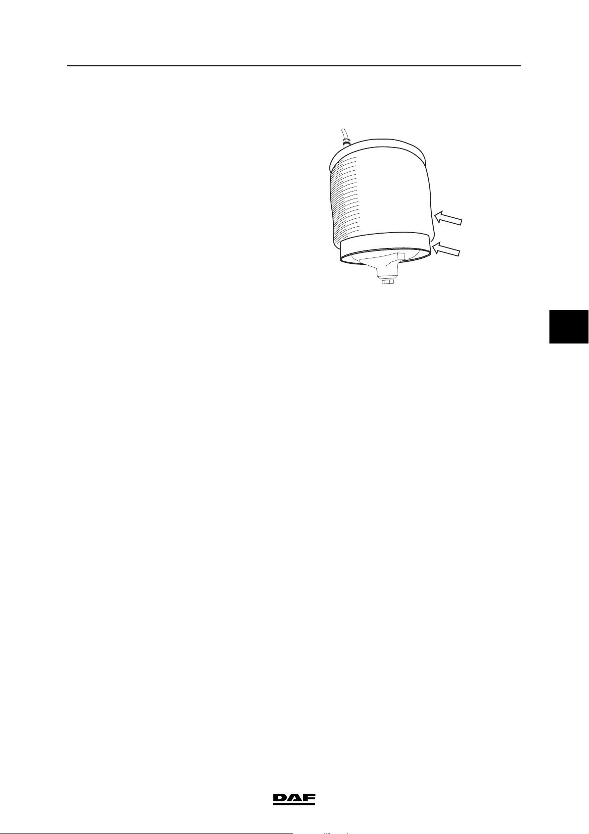
EXPLANATORY NOTES ON THE MAINTENANCE ACTIVITIES
ΛΦ45/55 series
3.42 CHECKING THE AIR SUSPENSION BELLOWS
1. Raise the chassis to driving height using the
remote control.
2. Clean the air bellows using a cleaning cloth
or a soap solution, if required.
3. Check the air bellows for cracks and
damage. If there are any cracks or damage
through which the webbing is visible, the air
bellows should be replaced.
4. Check the air bellows, bellows seating and
air line connections for leaks.
Check that the air bellows are not chafing
against air lines, etc. when in the driving
position.
Inspection and adjustment
M9040
5
©
200515 3-35
Page 82
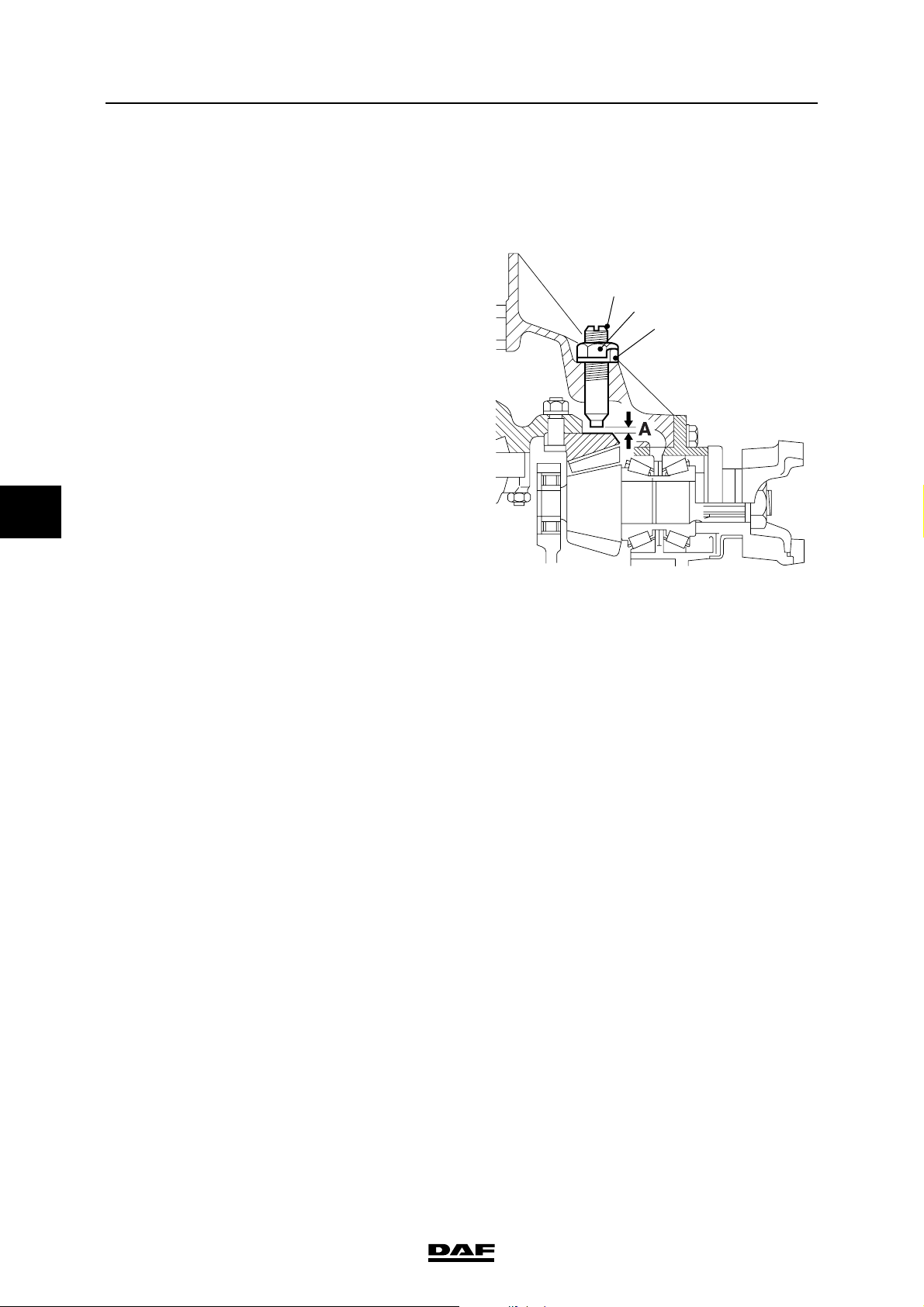
EXPLANATORY NOTES ON THE MAINTENANCE ACTIVITIES
5
Inspection and adjustment
3.43 ADJUSTING THE CROWN WHEEL GUIDE BOLT
1. Place chocks in front of the wheels and put
the vehicle on the parking brake.
2. Loosen the circlip (1) and slacken the lock
nut (2) a few turns.
3. Remove the adjusting screw (3) from the
differential.
4. Remove the circlip (1).
5. Remove the traces of sealant from the
adjusting screw and apply new sealant to the
last 4 windings of the thread, see "Technical
data".
6. Fit the adjusting screw with a new circlip and
turn the screw against the crown wheel.
7. Turn back the adjusting screw 1/8 of a turn to
obtain the required play A.
ΛΦ45/55 series
3
2
1
8. Tighten the attachment nut to the specified
torque. See "Technical data".
Note:
Make sure that the adjusting screw does not
turn when the lock nut is tightened.
9. Secure the lock nut by bending the circlip
lips.
A8 00 489
3-36
©
200515
Page 83
EXPLANATORY NOTES ON THE MAINTENANCE ACTIVITIES
ΛΦ45/55 series
Inspection and adjustment
3.44 INSPECTING THE REAR AXLE WHEEL BEARING PLAY
Inspecting the rear axle wheel bearing play
1. Jack up the rear axle until the wheels are
clear from the floor and position suitable
stands under the axle.
2. Check the wheel bearings manually for
noticeable play.
Note:
If noticeable play is detected, the wheel
bearing play should be re-adjusted.
5
©
200515 3-37
Page 84
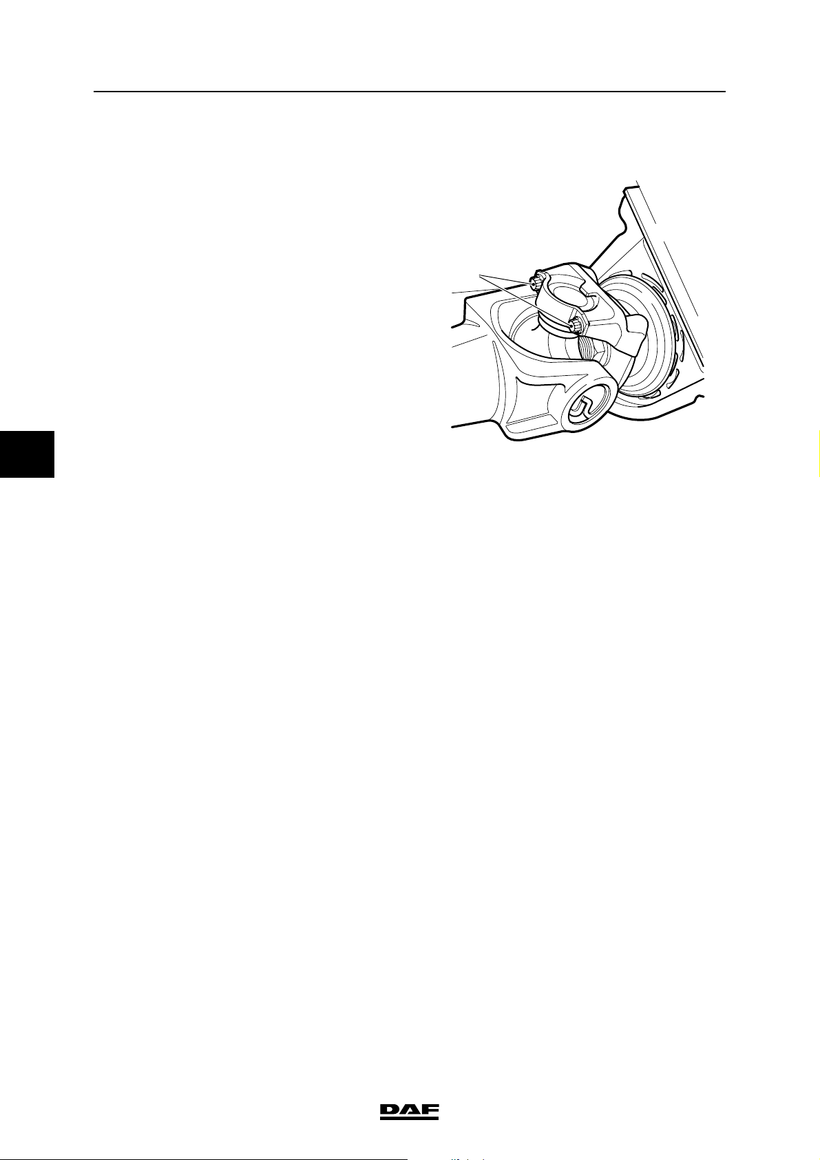
EXPLANATORY NOTES ON THE MAINTENANCE ACTIVITIES
5
Inspection and adjustment
ΛΦ45/55 series
3.45 CHECKING THE CLAMP OF THE DRIVE SHAFT UNIVERSAL JOINT
1. Retighten the attachment bolts (1) of the
clamps to the specified tightening torque,
see "Technical data".
Note:
The attachment bolts must not turn when
they are retightened.
Attachment bolts that turn when they are
retightened must be loosened and checked.
2. Tighten the loosened attachment bolts to the
specified torque. See "Technical data".
1
V3 00 377
3-38
©
200515
Page 85
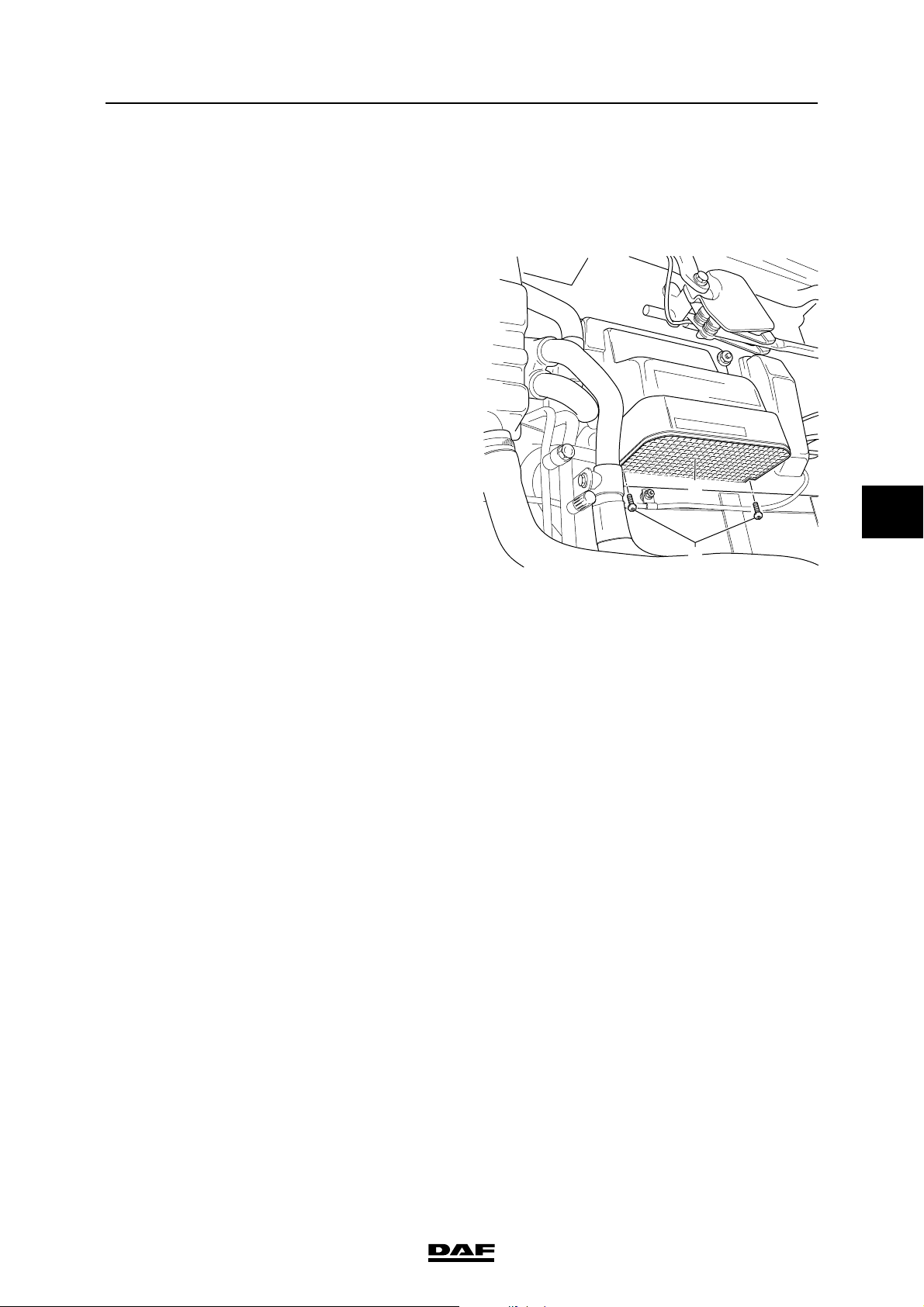
EXPLANATORY NOTES ON THE MAINTENANCE ACTIVITIES
ΛΦ45/55 series
Removal and installation
4. REMOVAL AND INSTALLATION
4.1 REMOVAL AND INSTALLATION, INTERIOR FILTER ELEMENT
Removing the interior filter element
1. Open the grille.
2. Remove the attachment bolts (1) from the
grate (2) on the underside of the filter casing.
3. Open the grate and remove the interior filter
element.
Installing the interior filter element
1. Install the interior filter element. Close the
grate (2) and fit the attachment bolts (1).
2. Close the grille.
Engine, cooling system and fuel system
2
5
1
K1 01 147
©
200515 4-1
Page 86

EXPLANATORY NOTES ON THE MAINTENANCE ACTIVITIES
5
Removal and installation
4.2 REMOVAL AND INSTALLATION, AIR FILTER ELEMENT
Removing the air filter element
1. Loosen all clamping brackets on the air filter
cover.
2. Remove the air filter cover.
3. Remove the air filter element.
4. Clean the inside of the air filter housing and
the air filter cover.
5. Clean the rubber sealing valves (1 and 2) on
the filter housing. Check the sealing valve for
damage.
Installing the air filter element
1. Fit the air filter element in the air filter
housing.
2. Fit the air filter cover.
3. Install all the clamping brackets.
4. Reset the air filter indicator (3) by pressing
the knob on the indicator.
2
1
ΛΦ45/55 series
3
I4 00 535
4-2
©
200515
Page 87
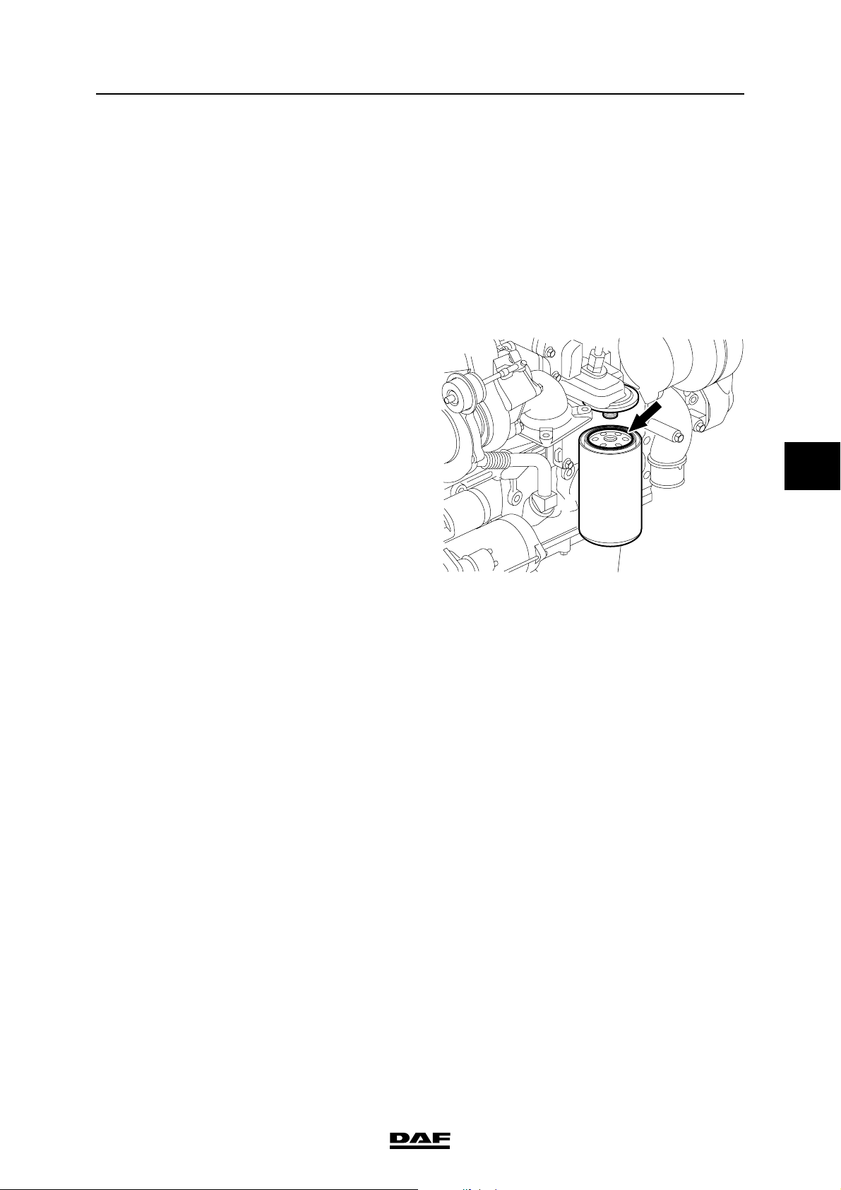
EXPLANATORY NOTES ON THE MAINTENANCE ACTIVITIES
ΛΦ45/55 series
4.3 REMOVAL AND INSTALLATION, LUBRICATING OIL FILTER
To prevent skin injury, avoid
unnecessary contact with the
}
drained lubricating oil.
Be careful when changing the oil.
Hot oil may cause serious injuries.
Removal and installation
}
Removing the lubricating oil filter
1. Place a tray beneath the lubricating oil filter.
2. Clean the area surrounding the filter element
if this is very dirty.
3. Remove the filter element by turning it anticlockwise. Collect the oil that comes out.
4. Remove the O-ring if it has not been
removed already.
Installing the lubricating oil filter
1. Lightly oil the filter element sealing ring.
5
2. Fill the filter element with clean oil. Use the
specified oil.
3. Fit the filter element onto the housing.
Tighten the filter element until the sealing
ring abuts. Tighten the filter element a further
• to 1 turn by hand.
4. Run the engine for a short time and check
that the lubricating oil filter is correctly
sealed.
5. Check the oil level and correct if necessary.
Use the specified oil.
G0 00 207
©
200515 4-3
Page 88
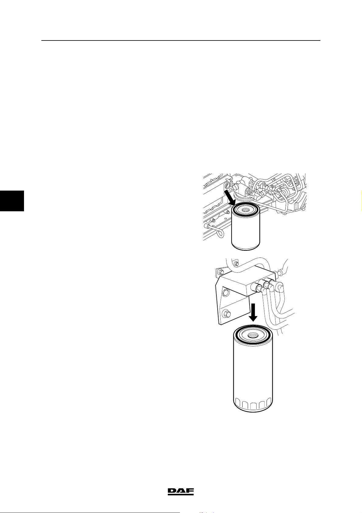
EXPLANATORY NOTES ON THE MAINTENANCE ACTIVITIES
5
Removal and installation
4.4 REMOVAL AND INSTALLATION, FUEL FINE FILTER
When removing the fuel fine filter, a
quantity of fuel will escape. Collect
}
Removing the fuel fine filter
1. Place a container beneath the fuel fine filter
Installing the fuel fine filter
Note:
Do not fill the fine filter with fuel until it has
been fitted. The fine filter is filled with fuel by
the primer pump after it has been fitted. This
considerably reduces the risk of dirt getting
into the fuel system.
1. Check by hand whether the coupling piece
the fuel and avoid the risk of fire.
and remove the filter.
Note:
The fuel fine filter is a disposable filter and
must therefore not be cleaned and re-used.
for the filter attachment is securely attached.
ΛΦ45/55 series
2. Lightly lubricate the filter sealing ring with
clean engine oil.
3. Fit the filter element onto the housing.
Tighten the filter element until the sealing
ring abuts. Tighten the filter element a further
∂ to • turn by hand.
4. Bleed the fuel system. See "Inspection and
adjustment".
5. Start the engine and check the fuel system
for leaks. If necessary, retighten the filter by
hand.
G0 00 201
i400964
4-4
©
200515
Page 89
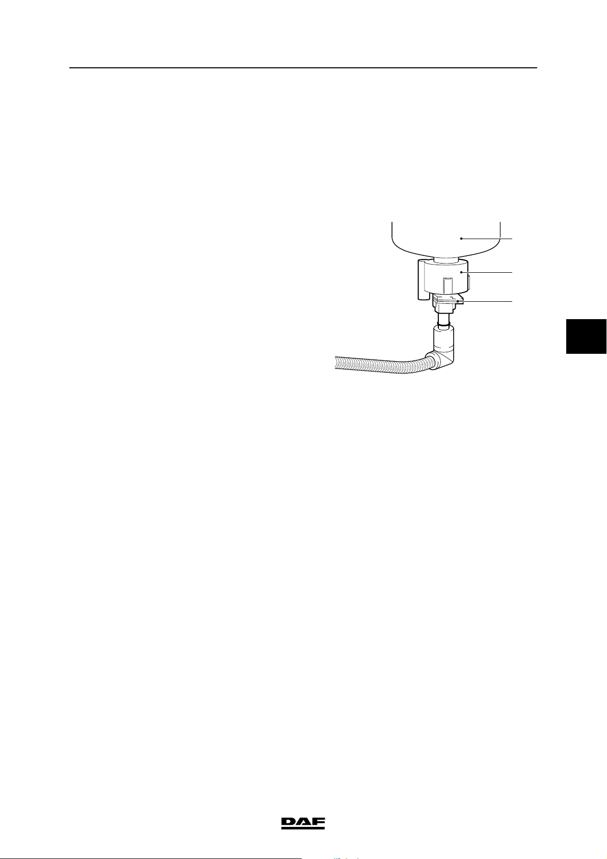
EXPLANATORY NOTES ON THE MAINTENANCE ACTIVITIES
ΛΦ45/55 series
Removal and installation
4.5 REMOVAL AND INSTALLATION, FUEL PREFILTER/WATER SEPARATOR
When removing the fuel prefilter/
water separator, a quantity of fuel
}
Removing the fuel prefilter/water separator
filter element
1. Place a container under the filter.
2. Remove the plug (3) from the water
3. Remove the fuel prefilter/water separator
4. Remove the water sensor (2) from the filter
Installing the fuel prefilter/water separator
filter element
1. Check by hand whether the coupling piece
will escape. Collect the fuel and
avoid the risk of fire.
sensor (2).
filter element (1) by turning it anti-clockwise.
element (1).
for the filter attachment is securely attached.
G0 00 220
1
2
3
5
2. Lightly lubricate the sealing ring with engine
oil.
3. Fit the fuel prefilter/water separator filter
element (1) until the sealing ring abuts.
Tighten the filter element a further ∂ to •
turn by hand.
4. Turn the water sensor (2) onto the filter
element until it abuts. Tighten the water
sensor by about a further - turn.
Note:
Over-tightening the water sensor (2) may
damage the sensor and/or cause leakage.
5. Fit the plug (3) on the water sensor (2).
6. Bleed the fuel system. See "Inspection and
adjustment".
7. Start the engine and check for leaks. If
necessary, retighten the fuel prefilter/water
separator filter element (1) by hand.
©
200515 4-5
Page 90

EXPLANATORY NOTES ON THE MAINTENANCE ACTIVITIES
5
Removal and installation
4.6 REMOVAL AND INSTALLATION, VALVE COVER
When the engine or parts of the
engine are opened, dirt can get in.
}
Removing the valve cover
1. Clean the area around the valve cover.
2. Remove the banjo bolt and the attachment of
3. Remove the valve cover attachment nuts.
4. Remove the valve cover.
Installing the valve cover
1. Clean the sealing surface of the valve sleeve
2. Check the valve cover gasket. If the valve
This may cause serious damage to
the engine. The engine should
therefore be cleaned thoroughly
before any parts are opened.
the plastic crankcase breather tube.
and the valve cover.
cover gasket is not damaged, it may be reused.
ΛΦ45/55 series
3. Fit the valve cover gasket to the valve cover.
4. Fit the valve cover.
5. Fit the valve cover attachment nuts and
tighten them to the specified torque; see
"Technical data".
6. Fit the plastic crankcase breather tube and
the banjo bolt to the valve cover.
Steering gear and brake s ystem
4-6
©
200515
Page 91
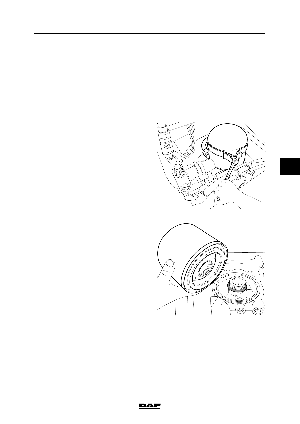
EXPLANATORY NOTES ON THE MAINTENANCE ACTIVITIES
ΛΦ45/55 series
Removal and installation
4.7 REMOVAL AND INSTALLATION, AIR DRYER FILTER ELEMENT
Note:
To be certain that the air dryer is functioning
properly, the air reservoirs should regularly be
checked for condensation. If more than the
normal amount of water is drained off repeatedly,
the air dryer element must be replaced. Under
normal circumstances the element must be
replaced at least once per year.
Removing air dryer filter element
1. Vent the air dryer by allowing it to regenerate
or by loosening the compressor line (1), so
that the interior of the air dryer is
depressurised.
2. Remove the filter element by turning it anticlockwise using a filter strap spanner.
3. Dispose of the drying element as if it were an
oil filter.
4. Clean the air dryer internally.
1
5
5. Check the air dryer threaded connection (2)
for damage and then lubricate it sparingly
with grease.
Installing the air dryer filter element
1. Lubricate the sealing ring of the new filter
element sparingly with grease.
2. Fit the filter element by manually tightening it
until the sealing ring abuts. Then tighten the
element by hand (approx. 1 turn).
3. Fasten the compressor line (1).
4. Pressurise the system and then check the air
dryer for any air leaks.
R600525
2
R600526
©
200515 4-7
Page 92
EXPLANATORY NOTES ON THE MAINTENANCE ACTIVITIES
5
Removal and installation
5. Using a water-resistant felt pen, write on the
sticker the latest date by which the dryer
element must be replaced (not later than
1 year after the date of fitting).
ΛΦ45/55 series
Artikelnummer
Reference
Teilenummer
Référence
1391510
Eerstvolgende vervanging
Next change
Nächster Wechsel
Prochain remplacement
R600523
4-8
©
200515
Page 93
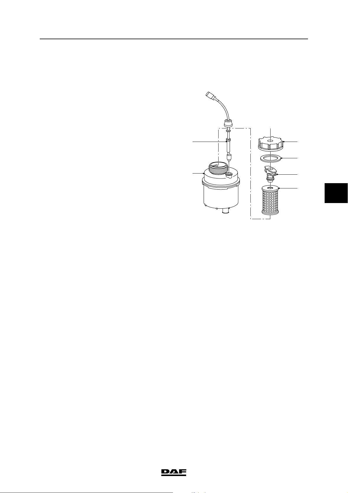
EXPLANATORY NOTES ON THE MAINTENANCE ACTIVITIES
ΛΦ45/55 series
Removal and installation
4.8 REMOVAL AND INSTALLATION, FILTER ELEMENT IN THE RESERVOIR OF
THE RAS-EC STEERING GEAR
Removing the filter element
1. Clean the reservoir cover, so that absolutely
no dirt can get into the reservoir.
2. Remove the cover (3).
3. Rotate the filter holder (5) a quarter turn and
slowly take the filter holder together with the
filter element (6) out of the reservoir.
2
Note:
The filter holder and filter element must be
removed from the reservoir with care so that
no dirt remains in the reservoir.
1
4. Remove the filter element (6) from the filter
holder (5).
Installing the filter element
1. Fit a new filter element (6) in the filter
holder (5).
2. Fit the filter holder (5) together with the filter
element (6) in the reservoir (1) and rotate the
filter holder (5) a quarter turn. Make sure that
the filter holder (5) engages in its locking
element.
3
4
5
6
S7 00 757
5
3. Check the sealing ring (4) for damage and
replace if necessary.
4. Fit the cover (3).
5. Check the fluid level.
©
200515 4-9
Page 94
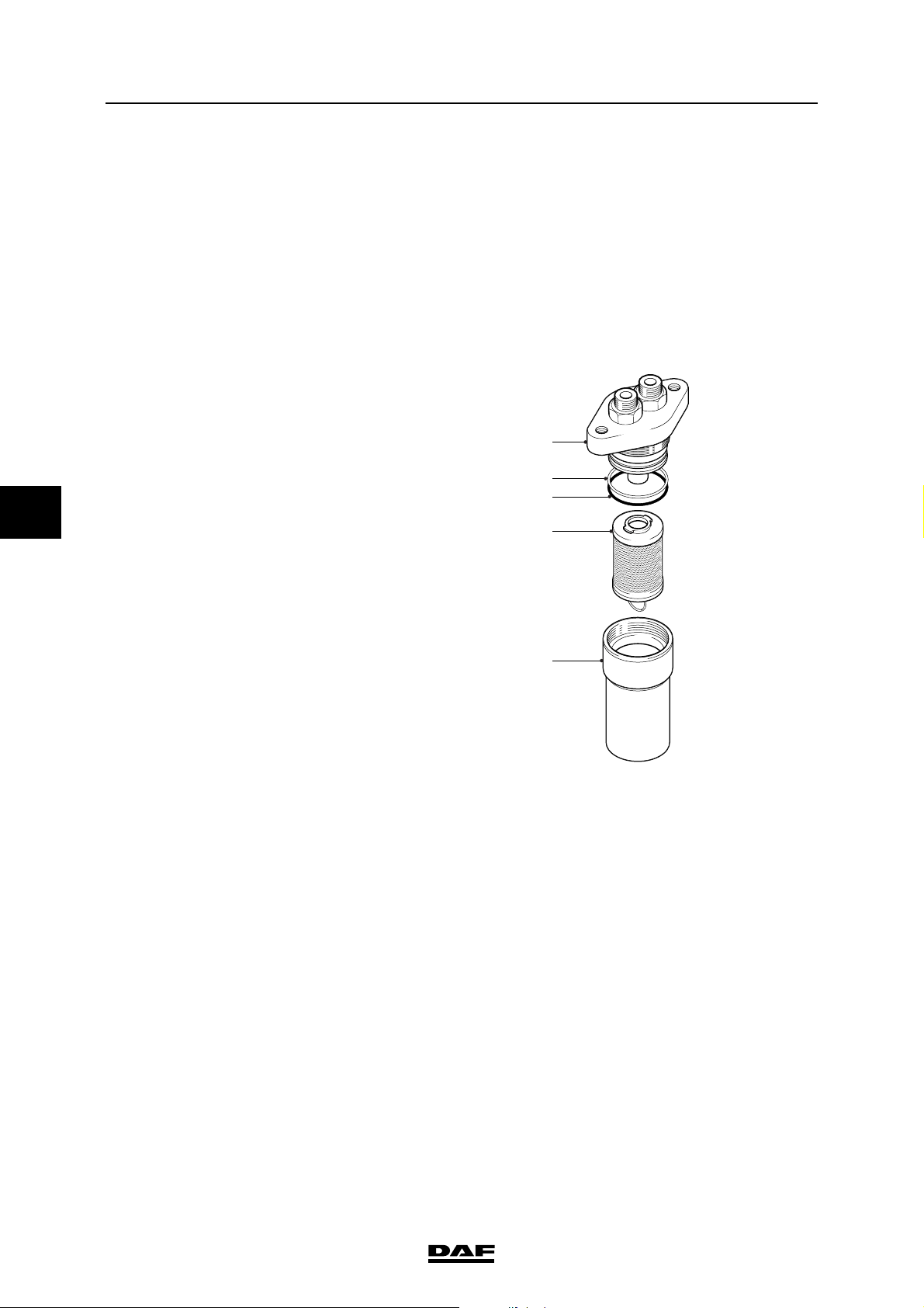
EXPLANATORY NOTES ON THE MAINTENANCE ACTIVITIES
5
Removal and installation
ΛΦ45/55 series
4.9 REMOVAL AND INSTALLATION, HIGH-PRESSURE FILTER OF THE RAS-EC
STEERING GEAR
Drained steering oil must not be reused. Store this hydraulic oil
{
Removing the high-pressure filter
1. Clean the high-pressure filter and the
2. Place a suitable receptacle under the high-
3. Remove the filter element (4).
4. Clean the filter cap (5).
separately from the other drained
oils and have the oil collected by a
waste-removal company authorised
to do so.
surrounding area.
pressure filter and remove the filter cap (5).
1
2
3
4
Installing the high-pressure filter
1. Check the sealing rings (2) and (3) and
replace them if necessary.
2. Fit a new filter element (4) in the filter
holder (1).
3. Fit the filter cap (5). Tighten the filter cap to
the specified tightening torque, see
"Technical data".
4. Top up the system, see chapter "Draining
and filling".
5. Check the operation of the system.
6. Check the high-pressure filter for leakage.
5
S7 00 688
4-10
©
200515
Page 95
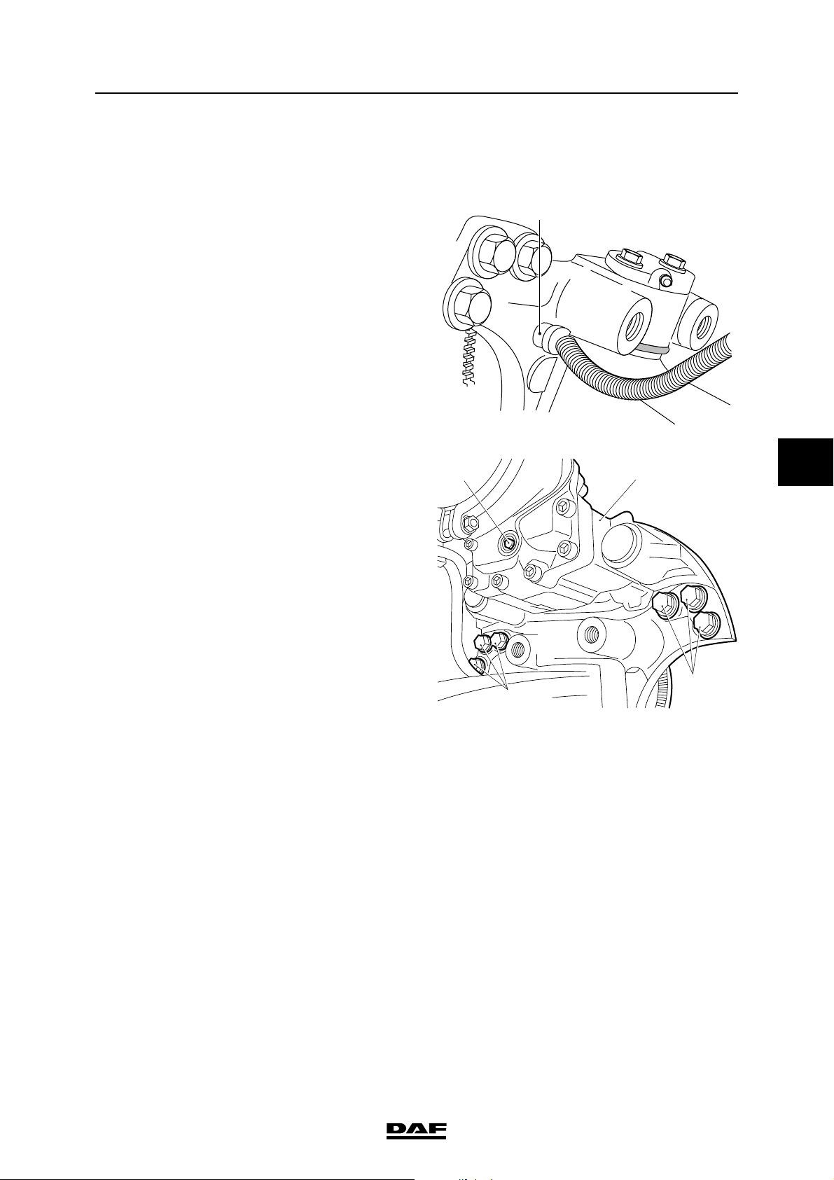
EXPLANATORY NOTES ON THE MAINTENANCE ACTIVITIES
ΛΦ45/55 series
Removal and installation
4.10 REMOVAL AND INSTALLATION, F36/F48 FRONT AXLE WHEEL HUB
Removing the hub
1. Support the front axle in a safe manner.
2. Remove the wheel.
3. Remove the wheel speed sensor (1).
4. Remove the cap placed over the adjusting
bolt (1). Reset the brake pads by unscrewing
the adjusting bolt (1) clockwise as far as it will
go.
1
1
2
S7 00 589
5
5. Remove the attachment bolts (3) from the
brake calliper (2). Remove the brake calliper
(2) with attached pipes from the stub axle.
Put the brake calliper (2) aside.
3
3
R600559
©
200515 4-11
Page 96
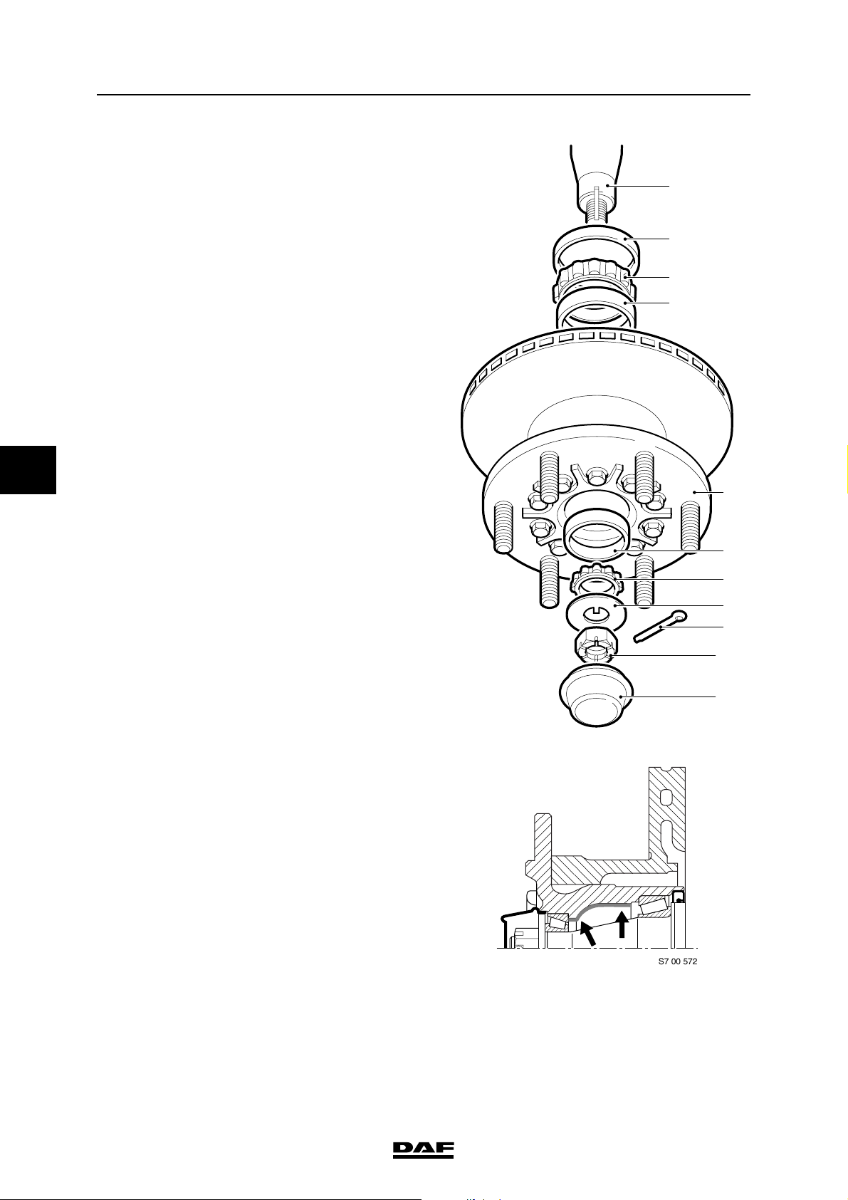
EXPLANATORY NOTES ON THE MAINTENANCE ACTIVITIES
;;;;
;;;;
;;;;
5
Removal and installation
6. Remove the hub cap (11).
7. Remove the lock nut (10).
8. Remove the hub (5) from the axle journal (1).
Save the circlip (8) and the bearing cage (7).
9. Remove the seal (2) from the hub (5).
10. Take the bearing cage (3) out of the hub (5).
Installing the hub
1. Clean the axle journal (1) and check for
damage.
2. Clean the bearing cages (3) and (7).
3. Remove the grease from the hub (5) and
clean the ball races (4) and (6).
4. Check the bearing cages (3) and (7) and the
ball races (4) and (6) for wear and damage.
If necessary, fit new wheel bearings.
ΛΦ45/55 series
1
2
3
4
5
5. Apply an ample quantity of the specified
grease to the bearing cages (3) and (7).
6. Fit the bearing cage (3) into the hub (5).
7. Apply a layer of grease (approx. 6 mm thick)
to the hub cavity.
6
7
8
9
10
11
S7 00 573
4-12
S7 00 572
©
200515
Page 97
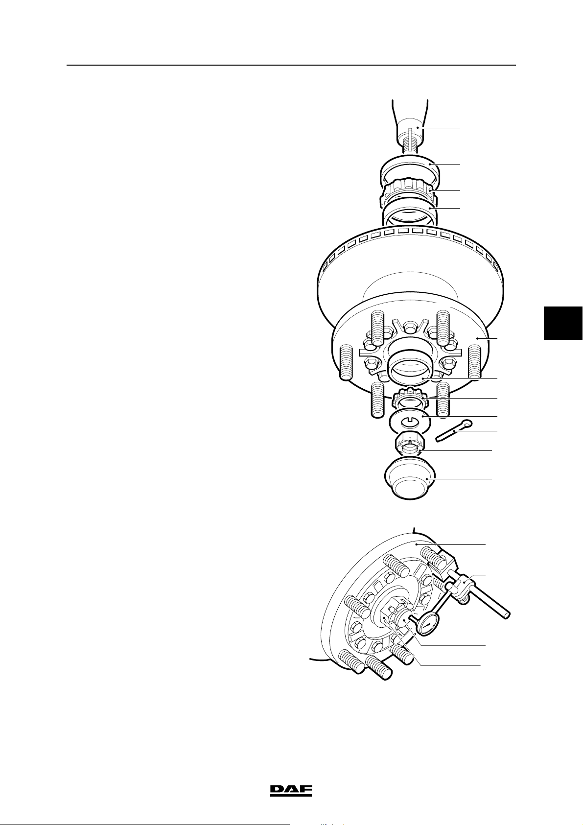
EXPLANATORY NOTES ON THE MAINTENANCE ACTIVITIES
ΛΦ45/55 series
8. Fit a new seal (2) in the hub (5).
9. Fit the hub (5) to the axle journal (1).
10. Fit the bearing cage (7).
11. Apply the specified grease to the front of the
bearing cage (7).
12. Install the circlip (8).
13. Fit the lock nut (10). Tighten the lock nut (10)
to the specified torque. See "Technical data".
Rotate the hub (1), while securing the lock
nut (10), to allow the bearings to set.
14. Turn the lock nut (10) back through
approximately 90. It should be possible to fit
the split pin (9).
Removal and installation
1
2
3
4
5
5
15. Place a micrometer (A) on the wheel hub (5).
Allow the stylus to rest on the end of the axle
journal (1).
16. Push and pull on the wheel hub (5). Check
the wheel bearing play and compare this with
the specified value. See "Technical data".
17. If necessary, correct the wheel bearing play
by tightening or loosening the lock nut (10).
18. Fit a new split pin (9) in the lock nut (10).
6
7
8
9
10
11
S7 00 573
5
A
1
19. Fit the hub cap (11). Attention: the hub cap
must not be filled with grease.
©
200515 4-13
10
S7 00 574
Page 98
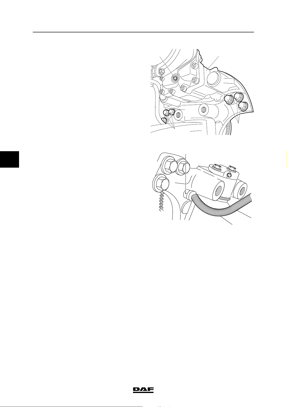
EXPLANATORY NOTES ON THE MAINTENANCE ACTIVITIES
5
Removal and installation
20. Apply locking compound to the attachment
bolts (3) of the brake calliper (2). See
"Technical data".
21. Install the brake calliper (2). Tighten the
attachment bolts (3) in the specified
sequence to the specified torque. See
"Technical data".
22. Set the brake pad clearance. To do this, turn
the adjusting bolt (1) anti-clockwise until the
brake pads abut the brake disc. Then turn
the adjusting bolt (1) clockwise through 90.
Check that the brake disc runs freely.
23. Fit the cap on the adjusting bolt (1).
24. Install the wheel speed sensor (1) and press
it against the sensor ring. The required
clearance will be produced while on the
move.
25. Fit the wheel.
ΛΦ45/55 series
1
2
3
3
R600559
1
S7 00 589
4-14
©
200515
Page 99
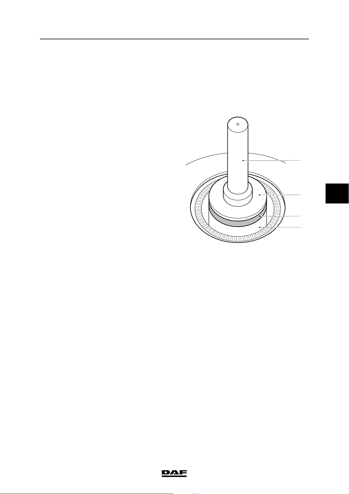
EXPLANATORY NOTES ON THE MAINTENANCE ACTIVITIES
ΛΦ45/55 series
Removal and installation
4.11 REMOVAL AND INSTALLATION, F36/F48 FRONT AXLE HUB SEAL
Removing the hub seal
1. Remove the seal from the hub using the
special tool (DAF no. 1329458). Make sure
that the chamber is not damaged during this.
Installing the hub seal
1. Fit special tool (A) (DAF no. 1329485) for
the F36 front axle and (DAF no. 1329484)
for the F48 front axle) in the driving tool (B)
(DAF no. 0499809).
2. Using the special tool, fit the new seal (1) in
the hub (2). The open side of the seal (1)
must face the hub (2). Apply a little grease to
the sealing lip of seal (1).
Drive and chassis
B
A
5
S7 00 588
1
2
©
200515 4-15
Page 100
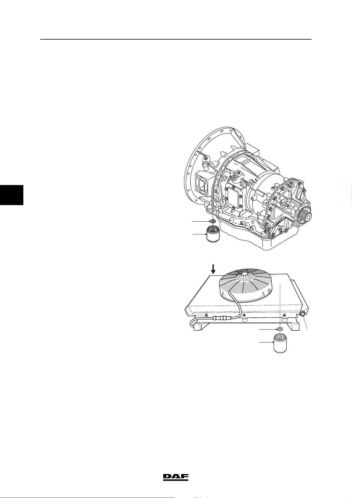
EXPLANATORY NOTES ON THE MAINTENANCE ACTIVITIES
5
Removal and installation
ΛΦ45/55 series
4.12 REMOVAL AND INSTALLATION, AUTOMATIC GEARBOX OIL FILTERS
Allison 1000 & 2000 series automatic gearbox
To prevent skin injury, avoid
unnecessary contact with the
}
Removing the oil filters
1. Clean the oil filter (1) and filter (5), if present,
2. Loosen the oil filters on the gearbox and heat
3. Remove the magnetic rings (2) and (4) and
drained oil.
as well as the surrounding area.
exchanger. Collect any oil that is flowing out.
check them for wear particles.
Note:
If there are larger wear particles in the wear
swarf, this points to advanced wear in the
gearbox. The cause must be tracked down.
4. Clean the magnetic rings and the contact
surfaces on the gearbox housing and the
heat exchanger.
Installing the oil filters
1. Fit the magnetic rings (2) and (4) on the
gearbox housing and the heat exchanger.
2. Lightly lubricate the new oil filter (1) and filter
(5), if present, with clean gearbox oil and
place the oil filters on the gearbox and heat
exchanger.
3. Tighten the oil filters until they touch the
contact surface. Manually tighten the oil
filters another 360.
4. Check the oil level, see chapter "Inspection
and adjustment".
2
1
V3 00 480
3
4
6
5
V3 00 556
4-16
©
200515
 Loading...