


Daewoo DTA-21 T2, DTA-20 T3, DTA-20 T2, DTA-20 T8, DTA-21 T5 Service Manual
...
Service Manual
51/55/63/71 Cm STEREO Color Television
MODEL
CHASSIS
DTA-20 T1/T2/T3/T8
DTA-21 T1/T2/T5/T9/Y1
DTE-25 G6/G7
DTE-28 G2/G6/G7/96/98/
A6/A7/G8/B1
CP-385
CP-385
CP-785
CP-785
S/M No. : CP385P-010
http : //svc.dwe.co.kr DEC. 1999
DAEWOO ELECTRONICS CO., LTD.

Service manual CP-385 / CP-785
Contents
1 - Main features ................................................................................................................................. 2
1-1 Specifications .................................................................................................................... 2
1-2 Channel table .................................................................................................................... 4
1-3 ATSS sorting method ........................................................................................................ 7
2 - Safety instruction.......................................................................................................................... 9
3 - Alignment instructions ................................................................................................................. 10
3-1 Microcontroller configuration : Service mode .................................................................... 10
3-2 Microcontroller configuration : Option................................................................................ 10
3-3 TV set Alignment............................................................................................................... 10
4 - IC description ................................................................................................................................ 13
4-1 TDA936x TV signal processor - TXT with embedded m-Controller. ..................................13
4-2 MSP3415D Multistandard Sound Processor..................................................................... 21
4-3 TDA894xJ Stereo Audio Amplifier..................................................................................... 25
4-4 TDA835xJ Vertical Amplifier.............................................................................................. 26
4-4-1 TDA8357J............................................................................................................... 26
4-4-1 TDA8358J............................................................................................................... 28
4-5 TDA6107Q ........................................................................................................................ 29
4-6 24C08 8 Kbit EEPROM ..................................................................................................... 30
4-7 STR - F6653...................................................................................................................... 31
5 - Circuit description......................................................................................................................... 33
5-1 Block diagram.................................................................................................................... 33
5-2 IF ....................................................................................................................................... 37
5-3 Source switching ............................................................................................................... 39
5-4 m-Controller I/O pin configuration and function.................................................................. 39
5-5 Sound processing.............................................................................................................. 40
5-6 Sound amplification........................................................................................................... 43
5-7 Vertical deflection .............................................................................................................. 43
5-8 Power supply (STR F6653)............................................................................................... 45
5-9 TV start-up, TV normal run and stand by mode operations ..............................................49
6 -Service parts list............................................................................................................................. 56
6-1 DTA-21Y1L(CP-385) ........................................................................................................ 56
6-2 DTE-28G2F(CP-785)......................................................................................................... 62
7 - Exploded view ...............................................................................................................................
8 - PCB Layout....................................................................................................................................
9 - Circuit Diagram..............................................................................................................................
69
89
91
Service manual CP 385 / CP785
- 2 -
1-1 Specifications
TV standard
PAL - SECAM B/G D/K, PAL I/I, SECAM L/L’
Sound system
NICAM B/G, I, D/K, L,
FM 2Carrier B/G, D/K
Power consumption
21” : 49 W approx.
28” : 75 W approx.
Sound Output Power
21” : 4.5W x 2 (at 60% mod, 10%THD)
28” : 7W x 2 (at 60% mod, 10%THD)
Speaker
20”, 21” : 7W 8 ohm x2
25”, 28” : 12W 8 ohm x2
Teletext system
10 pages memory FASTEXT (FLOF or TOP)
Aerial input
75 ohm unbalanced
Channel coverage
Off-air channels, S-cable channels and hyperband
Tuning system
frequency synthesiser tuning system
Visual screen size
20” : 48 cm
21” : 51 cm
25” : 59 cm
28” : 66cm
Channel indication
On Screen Display
Program Selection
100 programmes
Aux. terminal
EURO-SCART 1 : Audio / Video In and Out, R/G/B In, Slow and
Fast switching.
EURO-SCART 2 : Audio / Video In, SVHS In.
Audio-Video Jack on front of cabinet in common connection with
EURO-SCART 2.
Headphone jack (3.5 mm) on front of cabinet
Remote Control Unit
R-40A01
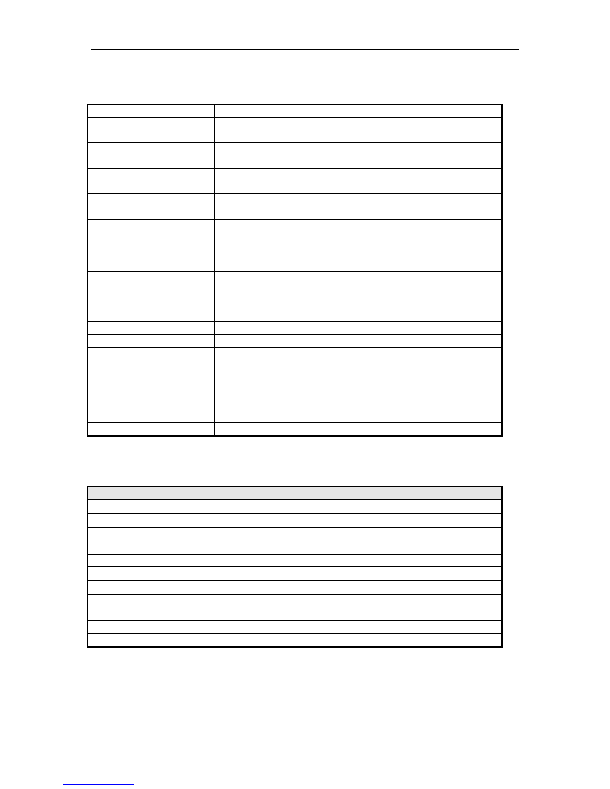
21 Pin EURO-SCART 1 :
Pin Signal Description Matching value
1 Audio Output Right
0.5 Vrms, Impedance < 1 kΩ, ( RF 54% Mod )
2 Audio Input Right
0.5 Vrms, Impedance > 10 kΩ
3 Audio Output Left
0.5 Vrms, Impedance < 1 kΩ, ( RF 54% Mod )
4 Audio Earth
5 Blue Earth
6 Audio Input Left
0.5 Vrms, Impedance > 10 kΩ
7 Blue Input
0.7 Vpp ±0.1V, Impedance 75Ω
8 Slow Switching TV : 0 to 2V, AV 16/9 : 4.5 to 7V, AV 4/3 : 9.5 to 12V ,
Impedance > 10 kΩ
9 Green Earth
10 N.C.
Service manual CP 385 / CP785
- 3 -
Pin Signal Description Matching value
11 Green Input
0.7 Vpp ± 0.1V, Impedance 75W
12 N.C.
13 Red Earth
14 Blanking Earth
15 Red Input
0.7 Vpp ± 0.1V, Impedance 75W
16 Fast Switching
0 to 0.4V : Logic “0” , 1 to 3V : Logic “1” , Impedance 75W
17 Video Out Earth
18 Video In Earth
19 Video Output
1 Vpp ± 3dB, Impedance 75W
20 Video Input
1 Vpp ± 3dB, Impedance 75W
21 Common Earth
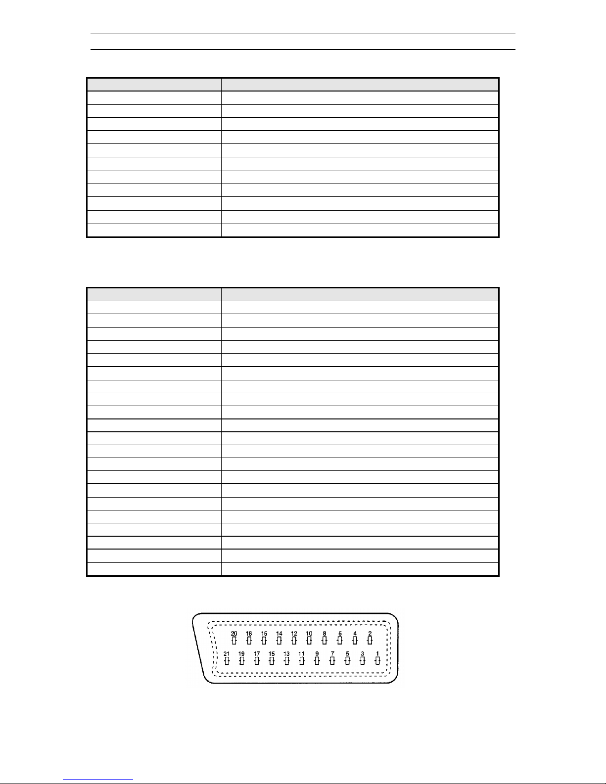
21 Pin EURO-SCART 2 :
Pin Signal Description Matching value
1 N.C.
2 Audio Input Right
0.5 Vrms, Impedance > 10 kW
3 N.C.
4 Audio Earth
5 Earth
6 Audio Input Left
0.5 Vrms, Impedance > 10 kW
7 N.C.
8 N.C.
9 N.C.
10 N.C.
11 N.C.
12 N.C.
13 Earth
14 Earth
15 Chroma Input
± 3dB for a luminance signal of 1 Vpp
16 N.C.
17 Earth
18 Video In Earth
19 N.C.
20 Video Input, Y In.
1 Vpp ± 3dB, Impedance 75W
21 Common Earth
Service manual CP 385 / CP785
- 4 -
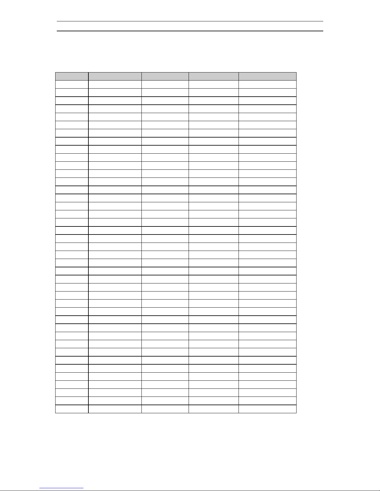
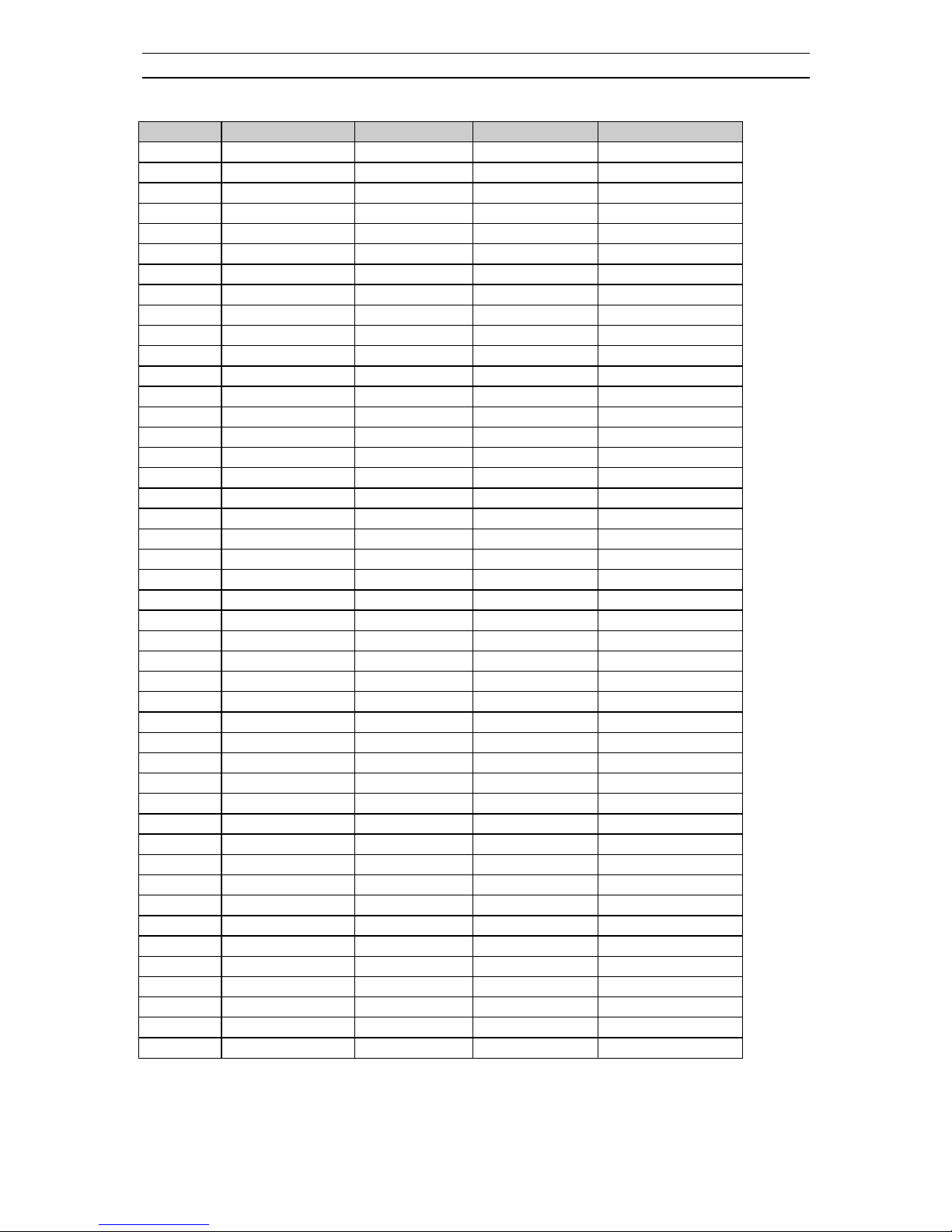
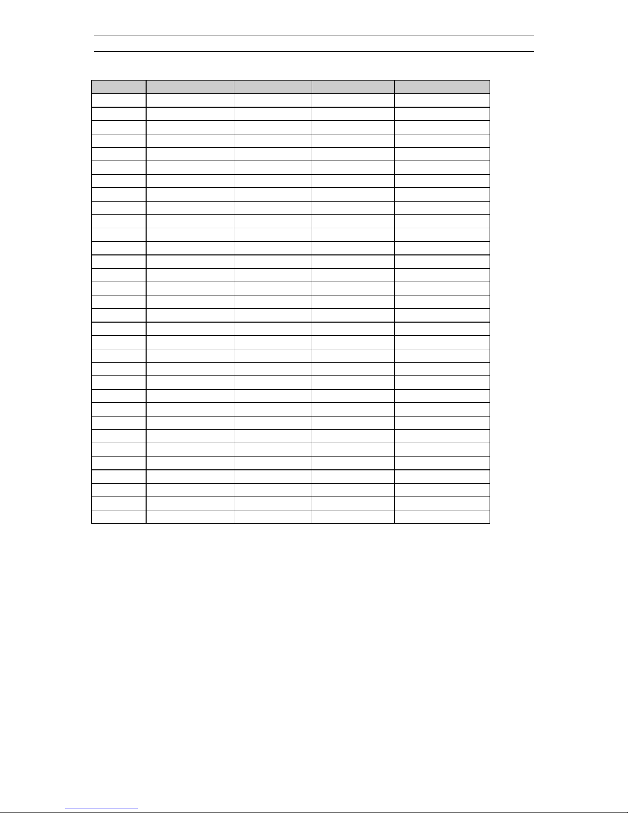
1-2 Channel table
FREQUENCY TABLE CP385/CP785
CH EUROPE CCIR
FRANCE GB(IRELAND)
EAST OIRT
C01
46.25 47.75 (L') 45.75 49.75
C02
48.25 55.75 (L') 53.75 59.25
C03
55.25 60.5 (L') 61.75 77.25
C04
62.25 63.75 (L') 175.25 85.25
C05
175.25 176.00 183.25 93.25
C06
182.25 184.00 191.25 175.25
C07
189.25 192.00 199.25 183.25
C08
196.25 200.00 207.25 191.25
C09
203.25 208.00 215.25 199.25
C10
210.25 216.00 223.25 207.25
C11
217.25 189.25 (LUX)
231.25 215.25
C12
224.25 69.25 (L') 239.25 223.25
C13
53.75 76.25 (L') 247.25 -
C14
- 83.25 (L') 49.75 -
C15
82.25 90.25 57.75 -
C16
- 97.25 65.75 -
C17
183.75 - 77.75 -
C18
192.25 - 85.75 -
C19
201.25 - - -
C20
- - - -
C21
471.25 471.25 471.25 471.25
C22
479.25 479.25 479.25 479.25
C23
487.25 487.25 487.25 487.25
C24
495.25 495.25 495.25 495.25
C25
503.25 503.25 503.25 503.25
C26
511.25 511.25 511.25 511.25
C27
519.25 519.25 519.25 519.25
C28
527.25 527.25 527.25 527.25
C29
535.25 535.25 535.25 535.25
C30
543.25 543.25 543.25 543.25
C31
551.25 551.25 551.25 551.25
C32
559.25 559.25 559.25 559.25
C33
567.25 567.25 567.25 567.25
C34
575.25 575.25 575.25 575.25
C35
583.25 583.25 583.25 583.25
C36
591.25 591.25 591.25 591.25
C37
599.25 599.25 599.25 599.25
C38
607.25 607.25 607.25 607.25
C39
615.25 615.25 615.25 615.25
C40
623.25 623.25 623.25 623.25
C41
631.25 631.25 631.25 631.25
Service manual CP 385 / CP785
- 5 -
CH EUROPE CCIR
FRANCE GB(IRELAND)
EAST OIRT
C42
639.25 639.25 639.25 639.25
C43
647.25 647.25 647.25 647.25
C44
655.25 655.25 655.25 655.25
C45
663.25 663.25 663.25 663.25
C46
671.25 671.25 671.25 671.25
C47
679.25 679.25 679.25 679.25
C48
687.25 687.25 687.25 687.25
C49
695.25 695.25 695.25 695.25
C50
703.25 703.25 703.25 703.25
C51
711.25 711.25 711.25 711.25
C52
719.25 719.25 719.25 719.25
C53
727.25 727.25 727.25 727.25
C54
735.25 735.25 735.25 735.25
C55
743.25 743.25 743.25 743.25
C56
751.25 751.25 751.25 751.25
C57
759.25 759.25 759.25 759.25
C58
767.25 767.25 767.25 767.25
C59
775.25 775.25 775.25 775.25
C60
783.25 783.25 783.25 783.25
C61
791.25 791.25 791.25 791.25
C62
799.25 799.25 799.25 799.25
C63
807.25 807.25 807.25 807.25
C64
815.25 815.25 815.25 815.25
C65
823.25 823.25 823.25 823.25
C66
831.25 831.25 831.25 831.25
C67
839.25 839.25 839.25 839.25
C68
847.25 847.25 847.25 847.25
C69
855.25 855.25 855.25 855.25
C70
863.25 863.25 863.25 863.25
C71
69.25 - - -
C72
76.25 - - -
C73
83.25 - - -
C74
90.25 - - -
C75
97.25 - - -
C76
59.25 - - -
C77
93.25 - - -
S01
105.25 104.75 103.25 105.25
S02
112.25 116.75 111.25 112.25
S03
119.25 128.75 119.25 119.25
S04
126.25 140.75 127.25 126.25
S05
133.25 152.75 135.25 133.25
S06
140.25 164.75 143.25 140.25
S07
147.25 176.75 151.25 147.25
S08
154.25 188.75 159.25 154.25
S09
161.25 200.75 167.25 161.25
Service manual CP 385 / CP785
- 6 -
CH EUROPE CCIR
FRANCE GB(IRELAND)
EAST OIRT
S10
168.25 212.75 - 168.25
S11
231.25 224.75 - 231.25
S12
238.25 236.75 - 238.25
S13
245.25 248.75 255.25 245.25
S14
252.25 260.75 263.25 252.25
S15
259.25 272.75 271.25 259.25
S16
266.25 284.75 279.25 266.25
S17
273.25 296.75 287.25 273.25
S18
280.25 136.00 295.25 280.25
S19
287.25 160.00 303.25 287.25
S20
294.25 - - 294.25
S21
303.25 303.25 - 303.25
S22
311.25 311.25 311.25 311.25
S23
319.25 319.25 319.25 319.25
S24
327.25 327.25 327.25 327.25
S25
335.25 335.25 335.25 335.25
S26
343.25 343.25 343.25 343.25
S27
351.25 351.25 351.25 351.25
S28
359.25 359.25 359.25 359.25
S29
367.25 367.25 367.25 367.25
S30
375.25 375.25 375.25 375.25
S31
383.25 383.25 383.25 383.25
S32
391.25 391.25 391.25 391.25
S33
399.25 399.25 399.25 399.25
S34
407.25 407.25 407.25 407.25
S35
415.25 415.25 415.25 415.25
S36
423.25 423.25 423.25 423.25
S37
431.25 431.25 431.25 431.25
S38
439.25 439.25 439.25 439.25
S39
447.25 447.25 447.25 447.25
S40
455.25 455.25 455.25 455.25
S41
463.25 463.25 463.25 463.25
Service manual CP 385 / CP785
- 7 -
1-3 ATSS sorting method
The TV set sweeps all the TV bands from beginning of VHF to end of UHF. The TV controlling
software for each program checks if a VPS CNI code is transmitted. If no VPS CNI code is found, the
system check if a CNI code is transmitted in the teletext lines ( Packet 8/30 format 1 ). If such a code
( VPS or teletext ) is found and if this code is in the ATSS list, the program is automatically named.
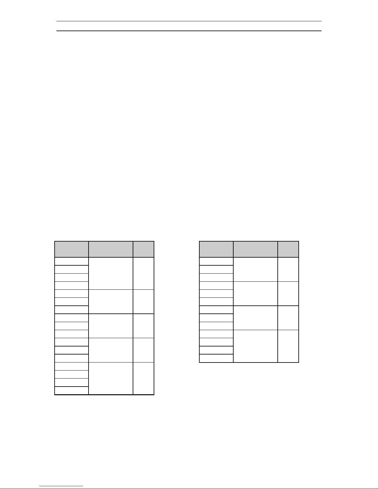
The programs found are then sorted in 4 groups :
Group I : It contains all the programs from the selected country and named by the TV controlling
software. Within this group the sorting order is fixed by the ATSS list.
Group II : It contains all the programs with a strong signal strength which are not listed in group I.
Group III : It contains all the programs with a weak signal strength which are not listed in group I.
Group IV : If two or more programs with the same code are found, only the strongest ( or if they have
the same level the one with the lowest frequency) is listed in group I, II or III. The others are listed in
group IV.
Note : If two programs with the same name but a different code are found these two programs are listed
in group I, II or III ( e.g. Regional program SW3 in Germany ).
The sorting order within group II, III, and IV is based on the channel frequency. The program with the
lowest frequency is allocated the first rank in its group, and so forth until the last program of the group
which has the highest frequency.
Program
number
Group Skip
1
2 Group I
...
n
n+1
... Group II
m
m+1
... Group III
p
p+1
... Group IV
q
q+1
... not used
4
99
0
Program
number
Group Skip
1
... Group II
m
m+1
... Group III
p
p+1
... Group IV
q
q+1
... not used
4
99
0
Special case : Country selection = Others

Service manual CP 385 / CP785
- 8 -
Special case : France
If France is selected the TV controlling software sweeps the whole TV bands firstly with France system
selected ( positive video modulation) and secondly with Europe system selected ( negative video
modulation).
Special case : Switzerland
If Switzerland is selected the TV controlling software sweeps the whole TV bands firstly with Europe
system selected (negative video modulation) and secondly with France system selected ( positive video
modulation).
Special case : GB
Note for satellite receiver users : Before starting ATSS turn On your satellite receiver and tune “ SKY
NEWS “.
If GB is selected the TV controlling software seeks for programs only in UHF ( C21 to C70 ). The
sorting order is :
1 - BBC1
2 - BBC2
3 - ITV
4 - CH4
5 - CH5
6 - NEWS
If two or more “ identical “programs ( same name but different code e.g. BBC1 and BBC1 Scotland )
are found the following programs in the list will be shifted up. (1 - BBC1, 2 - BBC1, 3 - BBC2, 4 ITV, 5 - CH4, 6 - CH5, 7 - NEWS, ..)
If one of the program above is not found, the associated program number remains empty ( freq.=467.25
Mhz - Skip selected - no name - system=GB).
example A : 1 - BBC1, 2 - BBC2, 3 - ITV, 4 - -----, 5 - CH5, 6 - NEWS, ...
example B ( if 2 BBC1 found ) : 1 - BBC1, 2 - BBC1, 3 - BBC2, 4 - ITV, 5 - -----, 6 - CH5, 7 NEWS, ...

Service manual CP 385 / CP785
- 9 -
2 - Safety instruction
WARNING: Only competent service personnel may carry out work involving the testing or repair of
this equipment.
X-RAY RADIATION PRECAUTION
1. Excessive high voltage can produce potentially hazardous X-RAY RADIATION. To avoid
such hazards, the high voltage must not exceed the specified limit. The nominal value of the high voltage
of this receiver is 25-26 KV (20”-21”) or 26 KV (25” - 28”) at max beam current. The high voltage
must not, under any circumstances, exceed 27.5 KV (20”), 29KV (21”), 29.5 KV (25") or 30 KV (28").
Each time a receiver requires servicing, the high voltage should be checked. It is important to use an
accurate and reliable high voltage meter.
2. The only source of X-RAY Radiation in this TV receiver is the picture tube. For continued X-RAY
RADIATION protection, the replacement tube must be exactly the same type tube as specified in
the parts list.
SAFETY PRECAUTION
1. Potentials of high voltage are present when this receiver is operating. Operation of the receiver
outside the cabinet or with the back board removed involves a shock hazard from the receiver.
1) Servicing should not be attempted by anyone who is not thoroughly familiar with the
precautions necessary when working on high voltage equipment.
2) Discharge the high potential of the picture tube before handling the tube. The picture tube is
highly evacuated and if broken, glass fragments will be violently expelled.
2. If any Fuse in this TV receiver is blown, replace it with the FUSE specified in the Replacement
Parts List.
3. When replacing a high wattage resistor (oxide metal film resistor) in circuit board, keep the resistor
10 mm away from circuit board.
4. Keep wires away from high voltage or high temperature components.
5. This receiver must operate under AC 230 volts, 5O Hz. NEVER connect to DC supply or any
other power or frequency.
PRODUCT SAFETY NOTICE
Many electrical and mechanical parts in this equipment have special safety-related characteristics.
These characteristics are often passed unnoticed by a visual inspection and the X-RAY RADIATION
protection afforded by them cannot necessarily be obtained by using replacement components rated for
higher voltage, wattage, etc. Replacement parts which have these special safety characteristics are
identified in this manual and its supplements, electrical components having such features are identified
by designated symbol on the parts list. Before replacing any of these components, read the parts list in
this manual carefully. The use of substitutes replacement parts which do not have the same safety
characteristics as specified in the parts list may create X-RAY Radiation.
Service manual CP 385 / CP785
- 10 -
3 - Alignment instructions
3-1 Microcontroller configuration : Service mode
To switch the TV set into service mode please see instruction below.
1 - Select pr. number 91
2 - Adjust sharpness to minimum and exit all menu.
3 - Quickly press the key sequence : RED - GREEN - menu
To exit SERVICE menu press menu key or Std By key.
In Service Mode press “OK” to stop the microcontroller i.e. the I2C bus is free and the set can be
controlled by external equipment. Press “OK” again to allow the microcontroller to control the set
again
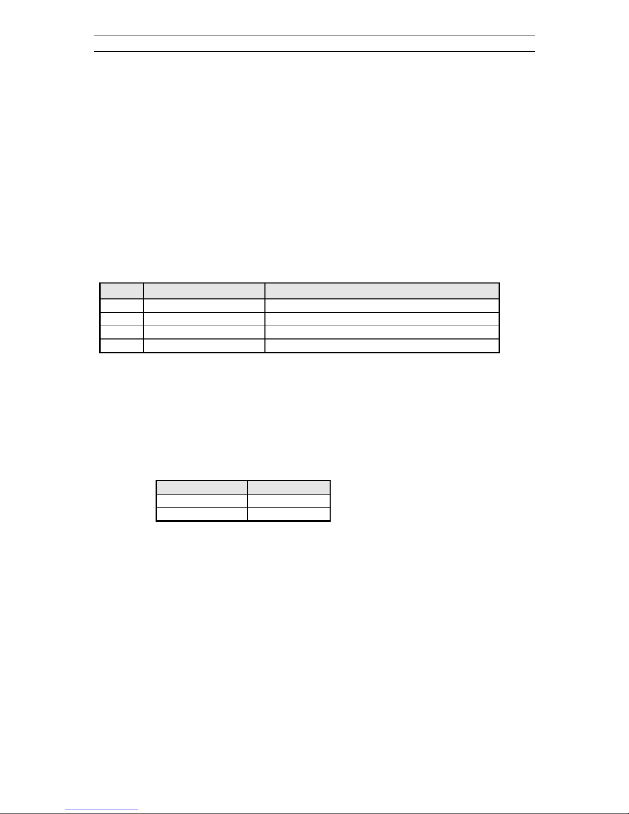
3-2 Microcontroller configuration : Option
Option
Tuner maker Remark
0 DAEWOO / SAMSUNG
1 DAEWOO / SAMSUNG
2 SIEL
3 PHILIPS Option 3 is available from software version 3 only
3-3 TV set Alignment
3-3-1 - G2 alignement
- TV in AV mode without video signal ⇒ Black screen.
- TV preset with WP Red, WP Green and WP Blue equal to 32.
- TV preset with Black R, Black G equal to 8.
- Set TV in NORMAL I mode
- Adjust screen volume ( on FBT ) such that the highest cathod cut-off voltage measured on CRT
board, is Vcut off ± 5V.
Screen size Vcut-off
20” & 21” 125 V
25” & 28” 140 V
3-3-2 - White balance
- Select a dark picture and adjust Black G and Black R to the desired colour temperature.
- Select a bright picture and adjust WP Red, WP Green, WP Blue to the desired colour temperature.
3-3-3 - Focus
- Adjust the Focus volume ( on FBT ) to have the best resolution on screen.
Service manual CP 385 / CP785
- 11 -
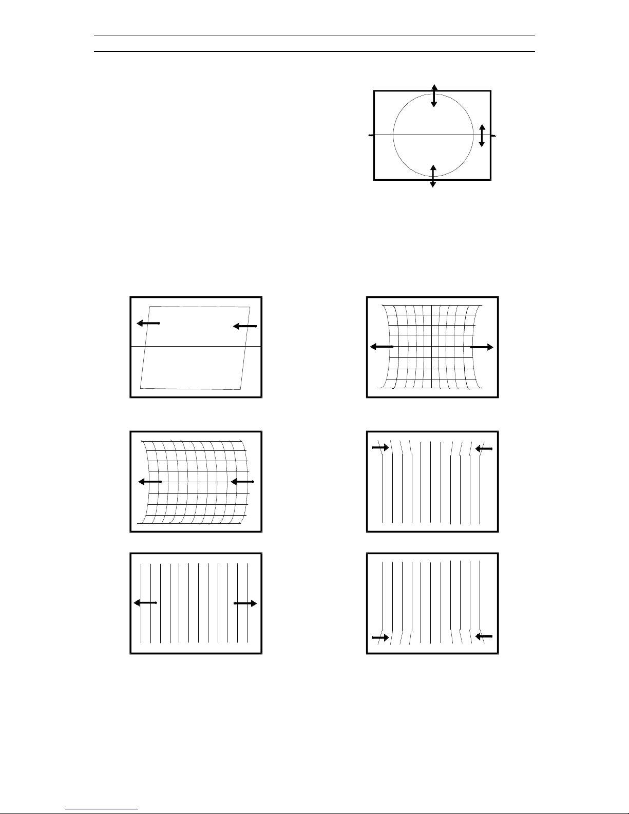
3-3-4 - Vertical geometry
- Adjust the Vertical Amplitude, Shift, S-
Correction and Slope to compensate for vertical
distortion.
3-3-5 - Horizontal picture centering
- Adjust H Shift to have the picture in the center of the screen.
3-3-6 - East / West correction ( Chassis CP785 only )
- Adjust the H Parall, H Bow, H Width, EW Parabo, Up Corner, Dw Corner, EW trapez to compensate
for geometrical distortion.
H. Parall
H. Bow
H.Width
EW.Parabo
Up Corner
Dw Corner

Service manual CP 385 / CP785
- 12 -
EW Trapez
3-3-7 - AGC
- Adjust the antenna signal level at 68 dBµV± 2 (UHF - CH25)
- Set RF AGC to 0.
- Increase RF AGC level and stop when the level on pin 6 of TDA936x goes below 2.5 Vdc

Service manual CP 385 / CP785
- 13 -
4 - IC description
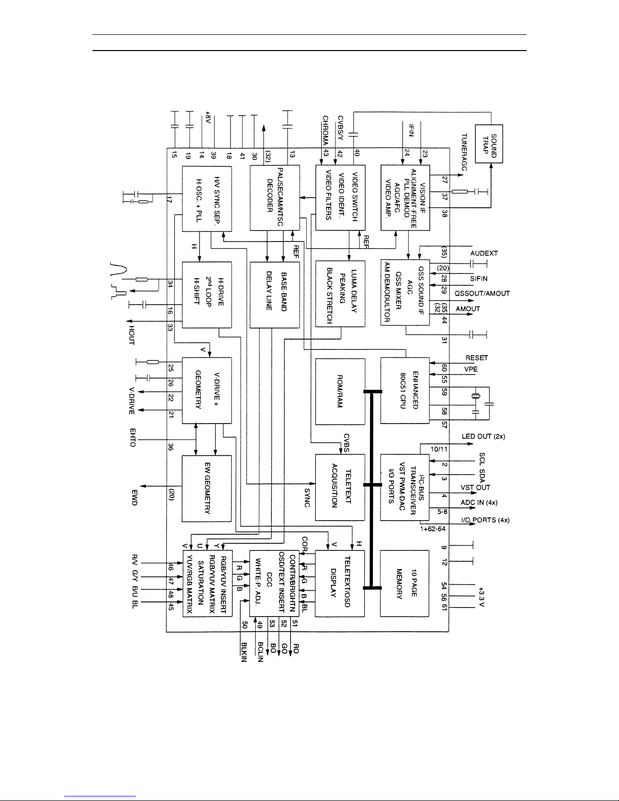
4-1 TDA936x TV signal processor - Teletext decoder with embedded µ-Controller.
TV-signal Processor
l Multi-standard vision IF circuit with alignment-free PLL demodulator
l Internal (switchable) time-constant for the IF-AGC circuit
l Source selection between 'Internal' CVBS and external CVBS or Y/C signals
l Integrated chrominance trap circuit
l Integrated luminance delay line with adjustable delay time
l Asymmetrical ‘delay line type’ peaking in the luminance channel
l Black stretching for non-standard luminance signals
l lntegrated chroma band-pass filter with switchable centre frequency
l Only one reference (12 MHz) crystal required for the µ-Controller, Teletext and the colour decoder
l PAL / NTSC or multistandard colour decoder with automatic search system
l Internal base-band delay line
l RGB control circuit with 'Continuous Cathode Calibration', white point and black level off set
adjustment so that the colour temperature of the dark and the bright parts of the screen can be chosen
independently.
l Linear RGB or YUV input with fast blanking for external RGB/YUV sources. The Text/OSD
signals are internally supplied from the µ-Controller/Teletext decoder
l Contrast reduction possibility during mixed-mode of OSD and Text signals
l Horizontal synchronisation with two control loops and alignment-free horizontal oscillator
l Vertical count-down circuit
l Vertical driver optimised for DC-coupled vertical output stages
l Horizontal and vertical geometry processing
l Horizontal and vertical zoom function for 16 : 9 applications
l Horizontal parallelogram and bow correction for large screen picture tubes
µ
-Controller
l 80C51 µ-controller core standard instruction set and timing
l 1µs machine cycle
l 32 - 128Kx8-bit late programmed ROM
l 3 - 12Kx8-bit Auxiliary RAM (shared with Display and Acquisition)
l Interrupt controller for individual enable/disable with two level priority
l Two 16-bit Timer/Counter registers
l WatchDog timer
l Auxiliary RAM page pointer
l 16-bit Data pointer
l IDLE and Power Down (PD) mode
l 14 bits PWM for Voltage Synthesis Tuning
l 8-bit A/D converter
l 4 pins which can be programmed as general I/0 pin, ADC input or PWM (6-bit) output
Data Capture
l Text memory 10 pages

Service manual CP 385 / CP785
- 14 -
l Inventory of transmitted Teletext pages stored in the Transmitted Page Table (TPT) and Subtitle
Page Table (SPT)
l Data Capture for US Closed Caption
l Data Capture for 525/625 line WST, VPS (PDC system A) and Wide Screen Signalling (WSS) bit
decoding Automatic selection between 525 WST/625 WST
l Automatic selection between 625 WST/VPS on line 16 of VBI
l Real-time capture and decoding for WST Teletext in Hardware, to enable optimised µ-processor
throughput
l Automatic detection of FASTEXT transmission
l Real-time packet 26 engine in Hardware for processing accented, G2 and G3 characters
l Signal quality detector for video and WST/VPS data types
l Comprehensive teletext language coverage
l Full Field and Vertical Blanking lnterval (VBI) data capture of WST data
Display
l Teletext and Enhanced OSD modes
l Features of lever 1.5 WST and US Close Caption
l Serial and Parallel Display Attributes
l Single/Double/Quadruple Width and Height for characters
l Scrolling of display region
l Variable flash rate controlled by software
l Enhanced display features including overlining, underlining and italics
l Soft colours using CLUT with 4096 colour palette
l Globally selectable scan lines per row (9/10/13/16) and character matrix [12x10, 12xl3, 12x16
(VxH)]
l Fringing (Shadow) selectable from N-S-E-W direction
l Fringe colour selectable
l Meshing of defined area
l Contrast reduction of defined area
l Cursor
l Special Graphics Characters with two planes, allowing four colours per character
l 32 software redefinable On-Screen display characters
l 4 WST Character sets (GO/G2) in single device (e.g. Latin, Cyrillic, Greek, Arabic)
l G1 Mosaic graphics, Limited G3 Line drawing characters
l WST Character sets and Closed Caption Character set in single device
Data Capture
The Data Capture section takes in the analogue Composite Vidéo and Blanking Signal (CVBS), and
from this extracts the required data, which is then decoded and stored in memory.
The extraction of the data is performed in the digital domain. The first stage is to convert the analogue
CVBS signal into a digital form. This is done using an ADC sampling at 12MHz. The data and clock
recovery is then performed by a Multi-Rate Video Input Processor (MuIVIP). From the recovered data
and clock the following data types are extracted WST Teletext (625/525), Closed Caption, VPS, WSS.
The extracted data is stored in either memory (DRAM) via the Memory Interface or in SFR locations.
Data Capture Features
- Video Signal Quality detector

Service manual CP 385 / CP785
- 15 -
- Data Capture for 625 line WST
- Data Capture for 525 line WST
- Data Capture for US Closed Caption
- Data Capture for VPS data (PDC system A)
- Data Capture for Wide Screen Signalling (WSS) bit decoding
- Automatic selection between 525 WST/625WST
- Automatic selection between 625WST/VPS on line 16 of VBI
- Real-time capture and decoding for WST Teletext in Hardware, to enable optimised microprocessor
throughput
- 10 pages stored On-Chip
- lnventory of transmitted Teletext pages stored in the Transmitted Page Table (TPT) and Subtitle Page
Table (SPT)
- Automatic detection of FASTEXT transmission
- Real-time packet 26 engine in Hardware for processing accented, G2 and G3 characters
- Signal quality detector for WST/VPS data types
- Comprehensive Teletext language coverage
- Full Field and Vertical Blanking Interval (VBI) data capture of WST data
Service manual CP 385 / CP785
- 16 -
Service manual CP 385 / CP785
- 17 -
TV processor version and µ-Controller capacity
IC version TDA9365 Nx / 3 TDA9367 Nx /3
TV range 110° 90°
QSS sound IF amplifier with
separated input and AGC circuit
ü
ü
PAL decoder
ü
ü
SECAM decoder
ü
ü
NTSC decoder
ü
ü
Horizontal geometry (E-W)
ü
Horizontal and vertical zoom
ü
ROM size 64 k 64 k
RAM size 2 k 2 k
Teletext 10 pages 10 pages
IC marking and version
Chassis IC marking
( line 3 )
OSD languages ATSS country Text
CP 385 DW9367/N1/3-AEx
( note : x is the
software version )
English, French,
German, Italian,
Spanish, Dutch,
Danish, Finnish,
Norwegian, Swedish
GB, France,
Germany,
Belgium, Spain,
Italy,
Switzerland,
Austria,
Denmark,
Finland,
Netherlands,
Norway,
Sweden, Ireland,
Others
Pan-European
( West )
CP 385 DW9367/N1/3-ADx
( note : x is the
software version )
English, Polish,
Russian, Hungarian,
Czech, Slovakian,
Romanian, Greek
Poland,
Hungary, Czech
rep., Others
Pan-European,
East, Cyrillic,
Greek.
CP 785 DW9365/N1/3-BE x
( note : x is the
software version )
English, French,
German, Italian,
Spanish, Dutch,
Danish, Finnish,
Norwegian, Swedish
GB, France,
Germany,
Belgium, Spain,
Italy,
Switzerland,
Austria,
Denmark,
Finland,
Netherlands,
Norway,
Sweden, Ireland,
Others
Pan-European
( West )
Service manual CP 385 / CP785
- 18 -
Chassis IC marking
( line 3 )
OSD languages ATSS country Text
CP 785 DW9365/N1/3-BDx
( note : x is the
software version )
English, Polish,
Russian, Hungarian,
Czech, Slovakian,
Romanian, Greek
Poland,
Hungary, Czech
rep., Others
Pan-European,
East, Cyrillic,
Greek.
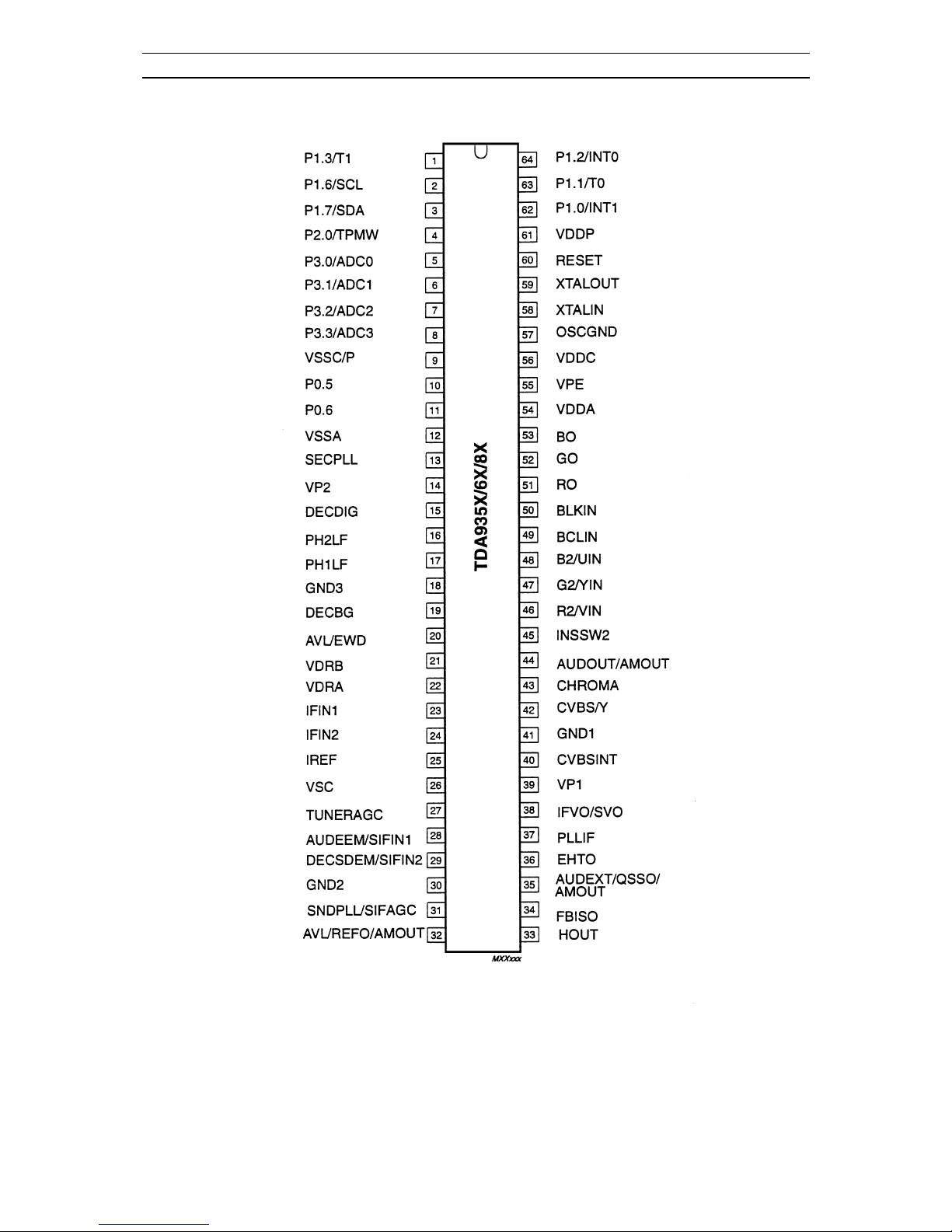
PINNING
SYMBOL PIN DESCRIPTION
n.u. 1 Port 1.3 Not used.
SCL 2 I2C bus clock line
SDA 3 I2C Data line
SECAM L’ out 4 Port 2.0 : High when L’ selected (PushPull )
OCP 5 Port 3.0 : Over Current Protection
RF AGC in 6 ADC 1 : For factory use only ( High impedance )
Key-in 7 ADC 2 : local key input ( High impedance )
S/SW 8 ADC 3 : Scart Slow switching input
VssC/P 9
digital ground for µ-controller core and peripheral
LED 1 10 port 0.5 ( 8mA current sinking capability )
LED 2 11 port 0.6 ( 8mA current sinking capability )
VSSA 12 analog ground of teletext decoder and digital ground of TV processor
SEC PLL 13 SECAM PLL decoupling
VP2 14 2nd supply voltage TV-processor
DECDIG 15 decoupling digital supply of TV-processor
PH2LF 16 phase-2 filter
PH1LF 17 phase-1 filter
GND3 18 ground 3 for TV-processor
DECBG 19 bandgap decoupling
AVL/EWD 20 East / West drive output
VDRB 21 vertical drive B output
VDRA 22 vertical drive A output
IFIN1 23 IF input 1
IFIN2 24 IF input 2
IREF 25 reference current input
VSC 26 vertical sawtooth capacitor
TUNERAGC 27 tuner AGC output
SIFIN1 28 SIF input 1
SIFIN2 29 SIF input 2
GND2 30 ground 2 for TV processor
SIF AGC 31 AGC sound IF
REF0 32 n.u.
HOUT 33 horizontal output
FBISO 34 flyback input / sandcastle output

Service manual CP 385 / CP785
- 19 -
SYMBOL PIN DESCRIPTION
QSS out 35 QSS intercarrier output
EHT0 36 EHT/Overvoltage protection
PLLIF 37 IF PLL loop filter
IFVO 38 IF video output
VP1 39 main supply voltage TV-processor
CVBSINT 40 internal CVBS input
GND1 41 ground 1 for TV-processor
CVBS/Y 42 external CVBS/Y input
CHROMA 43 chrominance input (SVHS)
AMOUT 44 n.u.
INSSW2 45 2nd RGB insertion input
R2IN 46 2nd R input
G2IN 47 2nd G input
B2IN 48 2nd B input
BCLIN 49 beam current limiter input
BLKIN 50 black current input
R0 51 RED Output
G0 52 GREEN Output
B0 53 BLUE Output
VDDA 54 analog supply of Teletext decoder and digital supply of TV-Processor
(3.3V)
VPE 55 OTP programming supply
VDDC 56 digital supply to core (3.3V)
OSCGND 57 oscillator ground supply
XTALIN 58 crystal oscillator input
XTALOUT 59 crystal oscillator output
RESET 60 reset
VDDP 61 digital supply to periphery (3.3V)
Audio Mute 62 Port 1.0 : Audio mute output (PushPull )
Power 63 Port 1.1 : Power output (PushPull )
IR in 64 Interrupt input 0 : R/C Infrared input
Service manual CP 385 / CP785
- 20 -

Service manual CP 385 / CP785
- 21 -
4-2 MSP3415D Multistandard Sound Processor
The MSP 3415D is designed as a single-chip Multistandard Sound Processor for applications in
analogue and digital TV sets, video recorders, and PC cards.
MSP 3415D features
- sound IF input
- No external filters required
- Stereo baseband input via integrated AD converters
- Two pairs of DA converters
- Two carrier FM or NICAM processing
- AVC : Automatic Volume Correction
- Bass, treble, volume processing
- Full SCART in/out matrix without restrictions
- Improved FM-identification
- Demodulator short programming
- Autodetection for terrestrial TV - sound standards
- Precise bit-error rate indication
- Automatic switching from NICAM to FM/AM or vice versa
- Improved NICAM synchronisation algorithm
- Improved carrier mute algorithm
- Improved AM-demodulation
- Reduction of necessary controlling
- Less external components
Basic Features of the MSP 3415D
Demodulator and NICAM Decoder Section
The MSP 3415D is designed to simultaneously perform digital demodulation and decoding of NICAMcoded TV stereo sound, as well as demodulation of FM or AM mono TV sound. Alternatively, two
carrier FM systems according to the German terrestrial specs can be processed with the MSP 3415D.
The MSP 3415D facilitates profitable multistandard capability, offering the following advantages:
- Automatic Gain Control (AGC) for analogue input: input range: 0.10 - 3 Vpp
- integrated A/D converter for sound-IF input
- all demodulation and filtering is performed on chip and is individually programmable
- easy realisation of all digital NICAM standards (B/G, I, L and D/K)
- FM-demodulation of all terrestrial standards (include identification decoding)
- no external filter hardware is required
- only one crystal clock (18.432 MHz) is necessary
- high deviation FM-mono mode (max. deviation: approx. ±360 kHz)
DSP-Section (Audio Baseband Processing)
- flexible selection of audio sources to be processed
- performance of terrestrial de-emphasise systems (FM, NICAM)
- digitally performed FM-identification decoding and de-matrixing
- digital baseband processing: volume, bass, treble
- simple controlling of volume, bass, treble
Analogue Section

Service manual CP 385 / CP785
- 22 -
- two selectable analogue pairs of audio baseband input (= two SCART inputs) input level: <2 V RMS,
input impedance: >25 kΩ
- one selectable analogue mono input (i.e. AM sound): Not used in this chassis
- two high-quality A/D converters, S/N-Ratio: >85 dB
- 20 Hz to 20 kHz bandwidth for SCART-to-SCART copy facilities
- loudspeaker: one pair of four-fold oversampled D/A converters
output level per channel: max. 1.4 VRMS output resistance: max. 5 kΩ
S/N-ratio: >85 dB at maximum volume max. noise voltage in mute mode: < 10 µV (BW: 20 Hz... 16
kHz)
- one pair of four-fold oversampled D/A converters supplying a pair of SCART-outputs.
output level per channel: max. 2 V RMS, output resistance: max. 0.5 kΩ,
S/N-Ratio: >85 dB (20 Hz... 16 kHz)
Application Fields of the MSP 3415D
In the following sections, a brief overview about the two main TV sound standards, NICAM 728 and
German FM Stereo, demonstrates the complex requirements of a multistandard audio IC.
NICAM plus FM/AM-Mono
According to the British, Scandinavian, Spanish, and French TV-standards, high-quality stereo sound is
transmitted digitally. The systems allow two high-quality digital sound channels to be added to the
already existing FM/AM-channel. The sound coding follows the format of the so-called Near
Instantaneous Companding System (NICAM 728). Transmission is performed using Differential
Quadrature Phase Shift Keying (DQPSK. Table below offers an overview of the modulation
parameters.
In the case of NICAM/FM (AM) mode, there are three different audio channels available: NICAM A,
NICAM B, and FM/AM-mono. NICAM A and B may belong either to a stereo or to a dual language
transmission. Information about operation mode and about the quality of the NICAM signal can be read
by the controlling software via the control bus. In the case of low quality (high bit error rate), the
controlling software may decide to switch to the analogue FM/AM-mono sound. Alternatively, an
automatic NICAM-FM/AM switching may be applied.
German 2-Carrier System (DUAL FM System)
Since September 1981, stereo and dual sound programs have been transmitted in Germany using the 2carrier system. Sound transmission consists of the already existing first sound carrier and a second
sound carrier additionally containing an identification signal. More details of this standard are given in
Tables below. For D/K very similar system is used.
Service manual CP 385 / CP785
- 23 -
TV standards
TV
system
Position of sound carrier
(MHz)
Sound modulation Color system Country
B/G 5.5 / 5.7421875 FM Stereo PAL Germany
B/G 5.5 / 5.85 FM-Mono / NICAM PAL Scandinavia,
Spain
L 6.5 / 5.85 AM - Mono / NICAM SECAM-L France
I 6.0 / 6.552 FM-Mono / NICAM PAL UK
D/K 6.5 / 6.2578125 D/K1
6.5 / 6.7421875 D/K2
6.5 / 5.85 D/K-NICAM
FM Stereo
FM-Mono / NICAM
SECAM-East USSR
Hungary
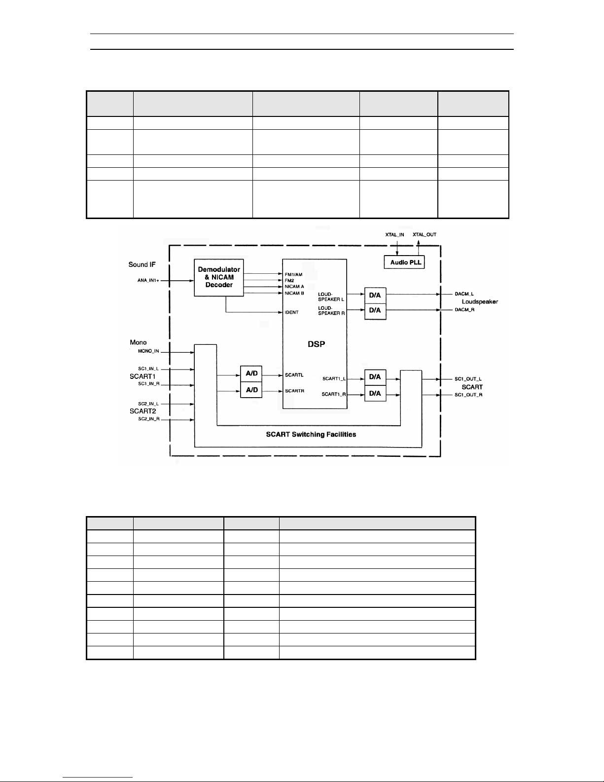
Architecture of MSP3415D
Pin connections and short description
Pin No.
Pin Name Type Short description
1 TP Out Test pin
2 NC Not Connected
3 NC Not Connected
4 TP Out Test pin
5 TP Out Test pin
6 ADR_SEL In I2C bus Address select
7 STANDBYQ In Standby ( Low-active)
8 NC Not Connected
9 I2C_CL In / Out I2C Clock
10 I2C_DA In / Out I2C data
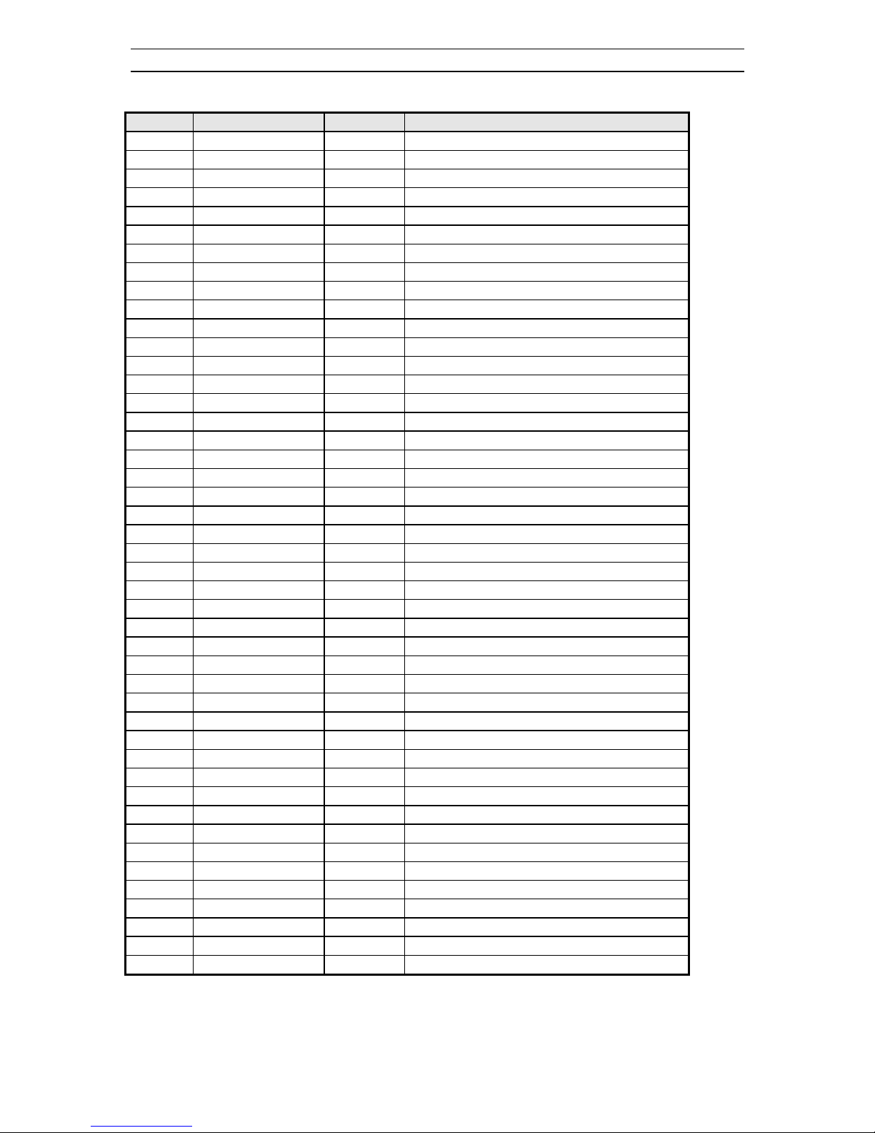
Service manual CP 385 / CP785
- 24 -
Pin No.
Pin Name Type Short description
11 TP In / Out Test pin
12 TP In / Out Test pin
13 TP Out Test pin
14 NC Not Connected
15 TP Out Test pin
16 TP Out Test pin
17 TP Out Test pin
18 DVSUP Digital power supply +5V
19 DVSS Digital Ground
20 NC Not Connected
21 NC Not Connected
22 NC Not Connected
23 NC Not Connected
24 RESETQ In Power-On-reset
25 NC Not Connected
26 NC Not Connected
27 VREF2 Reference ground 2 high voltage part
28 DACM_R Out Loudspeaker out Right
29 DACM_L Out Loudspeaker out Left
30 NC Not Connected
31 TP Out Test pin
32 NC Not Connected
33 NC Not Connected
34 NC Not Connected
35 VREF1 Reference ground 1 high voltage part
36 SC1_OUT_R Out Scart output 1, right
37 SC1_OUT_L Out Scart output 1, left
38 NC Not Connected
39 AHVSUP Analog power supply 8.0V
40 CAPL_M Volume capacitor MAIN
41 AHVSS Analog ground
42 AGNDC Analog reference voltage high voltage part
43 NC Not Connected
44 NC Not Connected
45 NC Not Connected
46 NC Not Connected
47 NC Not Connected
48 ASG2 Analog Shield Ground 2
49 SC2_IN_L In Scart input 2 in, left
50 SC2_IN_R In Scart input 2 in, right
51 ASG1 Analog Shield Ground 1
52 SC1_IN_L In Scart input 1 in, left
53 SC1_IN_R In Scart input 1 in, right
54 VREFTOP Reference voltage IF A/D converter
55 MONO_IN In Mono input
Service manual CP 385 / CP785
- 25 -
Pin No.
Pin Name Type Short description
56 AVSS Analog ground
57 AVSUP Analog power supply
58 ANA_IN1+ In IF input 1
59 ANA_IN1- In IF common
60 NC Not Connected
61 TESTEN In Test pin
62 XTAL_IN In Crystal oscillator
63 XTAL_OUT Out Crystal oscillator
64 NC Test pin
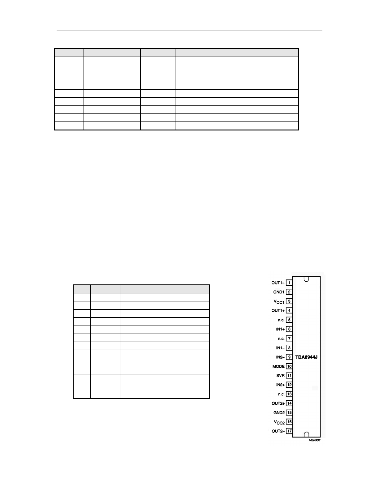
4-3 TDA894xJ Stereo Audio Amplifier
The TDA 8944J ( TDA 8946J ) is a dual-channel audio power amplifier with an output power of 2 x 7
W ( 2 x 15 W ) at an 8 W load and a 12 V supply. The circuit contains two Bridges Tied Load (BTL)
amplifiers with an all-NPN output stage and standby/mute logic. The TDA8944J comes in a 17-pin DIL
power package.
Features
Few external components
Fixed gain
Standby and mute mode
No on/off switching plops
low standby current
High supply voltage ripple rejection
Outputs short-circuit protected to ground, supply and across the load
Thermally protected
Pin description
Pin Symbol Description
1 OUT1- negative loudspeaker terminal 1
2 GND1 ground channel 1
3 Vcc1 supply voltage channel 1
4 OUT1+ positive loudspeaker terminal 1
5 n.c. not connected
6 IN1+ positive input1
7 n.c. not connected
8 IN1- negative input1
9 IN2- negative input2
10 MODE mode selection input
11 SVR half supply voltage decoupling
(ripple rejection)
12 IN2+ positive input2
Service manual CP 385 / CP785
- 26 -
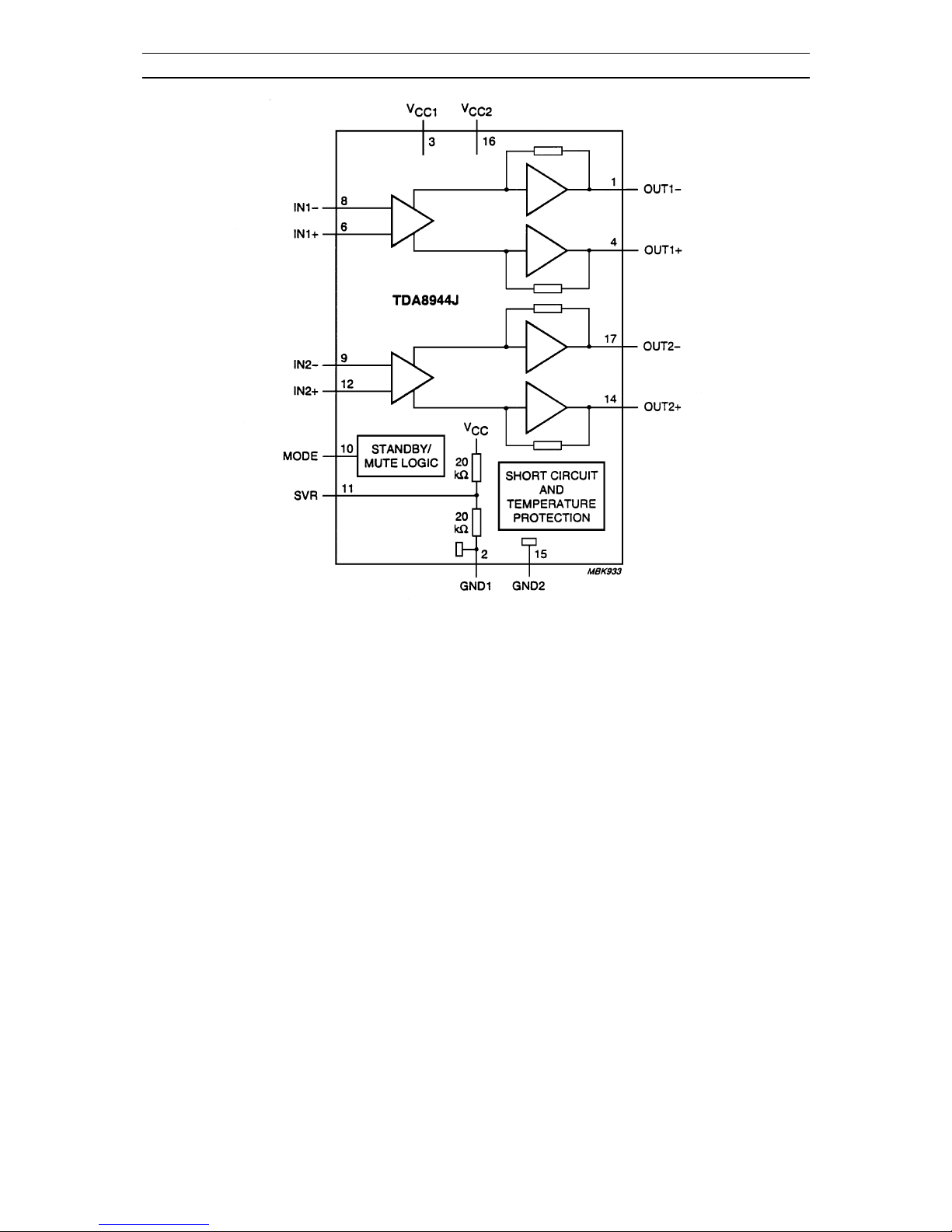
Block diagram TDA8944J
4-4 TDA835xJ Vertical Amplifier
The TDA835xJ are power circuit for use in 90° and 110° colour deflection systems for field frequencies
of 25 to 200Hz and 16/9 picture tubes. The circuit provides a DC driven vertical deflection output
circuit, operating as a highly efficient class G system. Due to the full bridge output circuit the deflection
coils can be DC coupled.
The IC is constructed in a Low Voltage DMOS process that combines Bipolar, CMOS and DMOS
devices. MOS transistors are used in the output stage because of the absence of second breakdown.
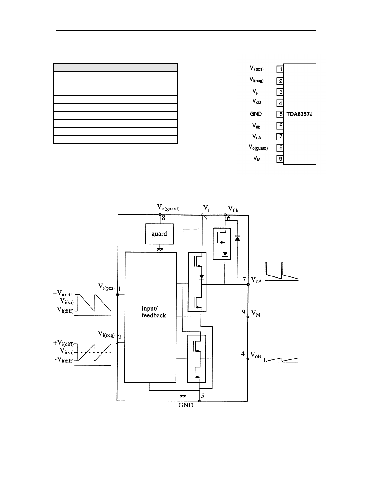
4-4-1 TDA8357J
Features :
- Few external components
- Highly efficient fully DC-coupled vertical output bridge circuit
- Short rise and fall time of the vertical flyback switch
- Guard circuit
- Temperature (thermal) protection
- High EMC because of common mode inputs
Service manual CP 385 / CP785
- 27 -
Pinning
Pin
Symbol Description
1 Vi(pos) input voltage (positive)
2 Vi(neg) input voltage (negative)
3 Vp supply voltage
4 VOB output voltage B
5 GND ground
6 Vflb flyback supply voltage
7 VOA output voltage A
8 V
O(guard)
guard output voltage
9 VM input measuring resistor
 Loading...