

DAEWOO DG-K301 Service Manual

Service Manual
✔ Caution :
In this Manual, some parts can be changed for improving, their
performance without notice in the parts list. So, if you need the latest
parts information,please refer to PPL(Parts Price List) in Service
Information Center.
DVD PLAYER
MODEL:
DG-K301
July. 2007

CONTENTS
CONTENTS
SPECIFICATIONS.........................................................................................................................2
CIRCUIT OPERATIONAL DESCRIPTION.........................................................................................3
VOLTAGE CHARTS.....................................................................................................................16
CIRCUIT DIAGRAM...................................................................................................................18
PCB CIRCUIT BOARD.................................................................................................................24
WAVEFORMS............................................................................................................................27
TROUBLE SHOOTING.................................................................................................................36
INSTRUMENT DISASSEMBLY......................................................................................................41
PARTLIST...................................................................................................................................42
1
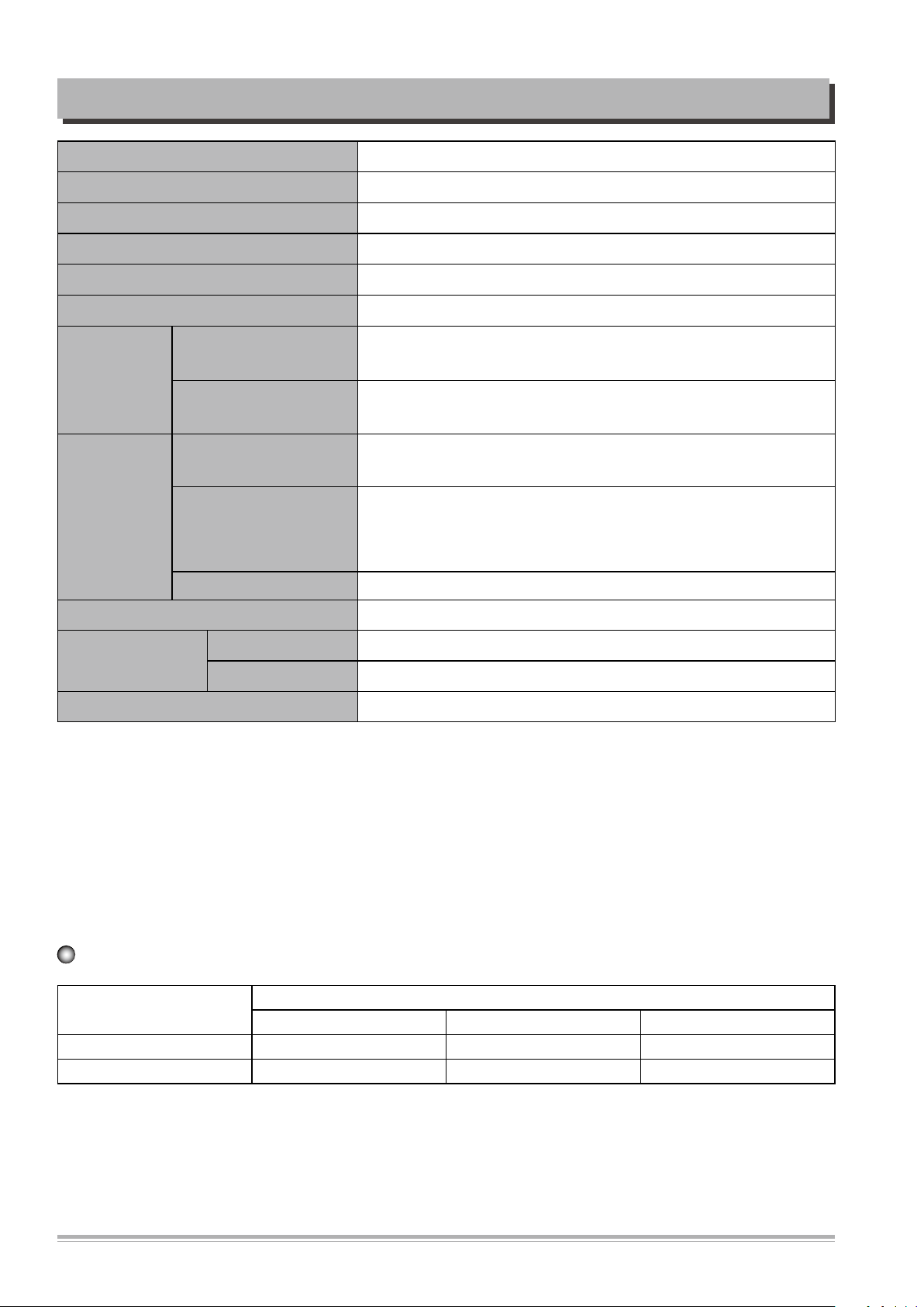
SPECIFICATIONS
Laser wavelength 650nm
Video PAL/AUTO/NTSC
Frequency response 20Hz ~ 20KHz (±1dB)
Signal/noise ratio ≥90dB
Channel separation ≥85dB ( 1KHz)
Dynamic range ≥80dB ( 1KHz)
output level : 2.0 + 0/-0.2Vrms
(Load impedance : 1,0KΩ)
output level : 0.5 ±0.1Vp-p
(Load impedance : 75Ω)
output level : 1.0 ±0.1Vp-p
(Load impedance : 75Ω, imbalance, negative polarity)
output level : brightness(Luma) 1.0 ±0.1Vp-p Chromaticity (Color)
0.286 ±20%
(Load impedance : 75Ω)
Output
Audio
Output
Video
Dimensiones
Weight (Gross / Net) 1.97Kg / 1.41Kg
Analog
Digital
Composite
S-video
Component Y: 1Vp-p, Pb/Pr: 0.7Vp-p (Load impedance : 75Ω)
Power 100-240V~, 50Hz~60Hz 12W
Body (W x H x D) 360 x 38 x 215 mm
Packing 437 x 90 x 280 mm
Notes : Design and specifications in this instruction manual are subjected to change without prior notice toimprove quality and function.
DVD Audio output standards
Output
DVD VIDEO-CD CD
Analogue Audio output 48/96KHz sampling 44.1KHz sampling 44.1KHz sampling
Digital Audio output 48KHz sampling 44.1KHz sampling 44.1KHz sampling
2
Disc type
CIRCUIT OPERATIONAL DESCRIPTION
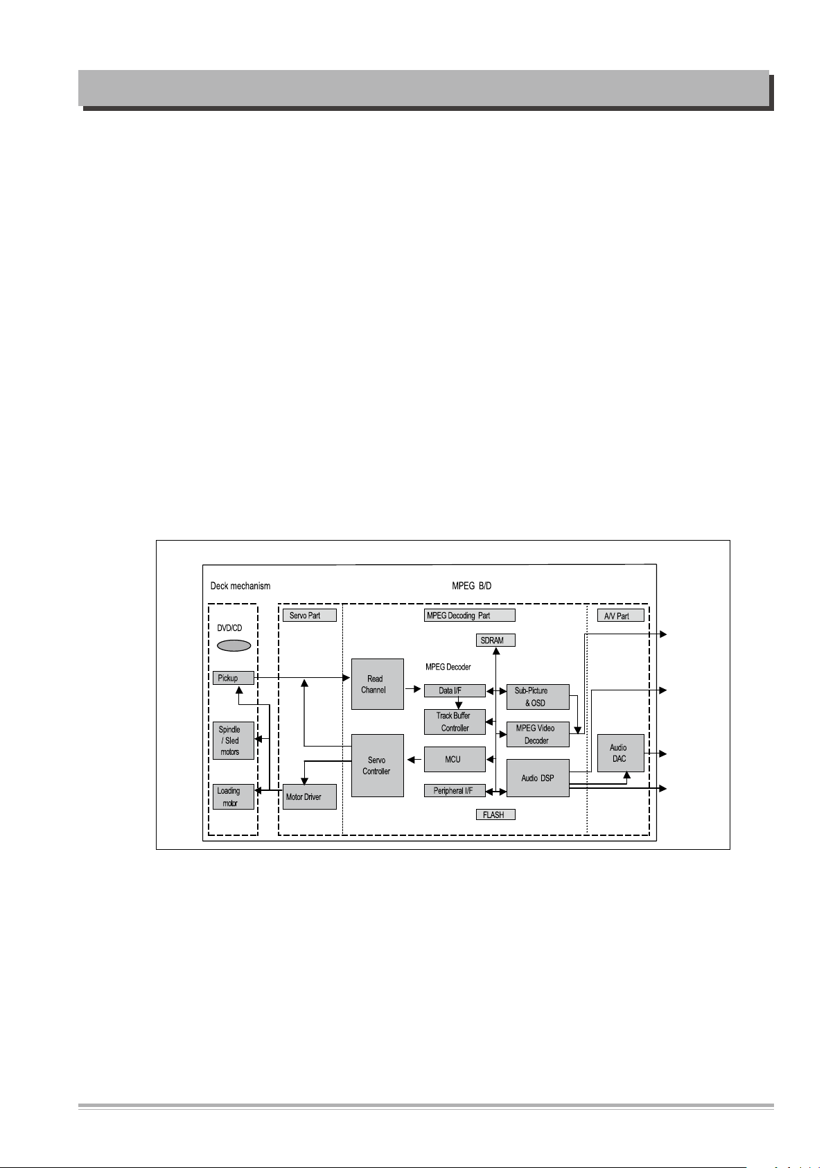
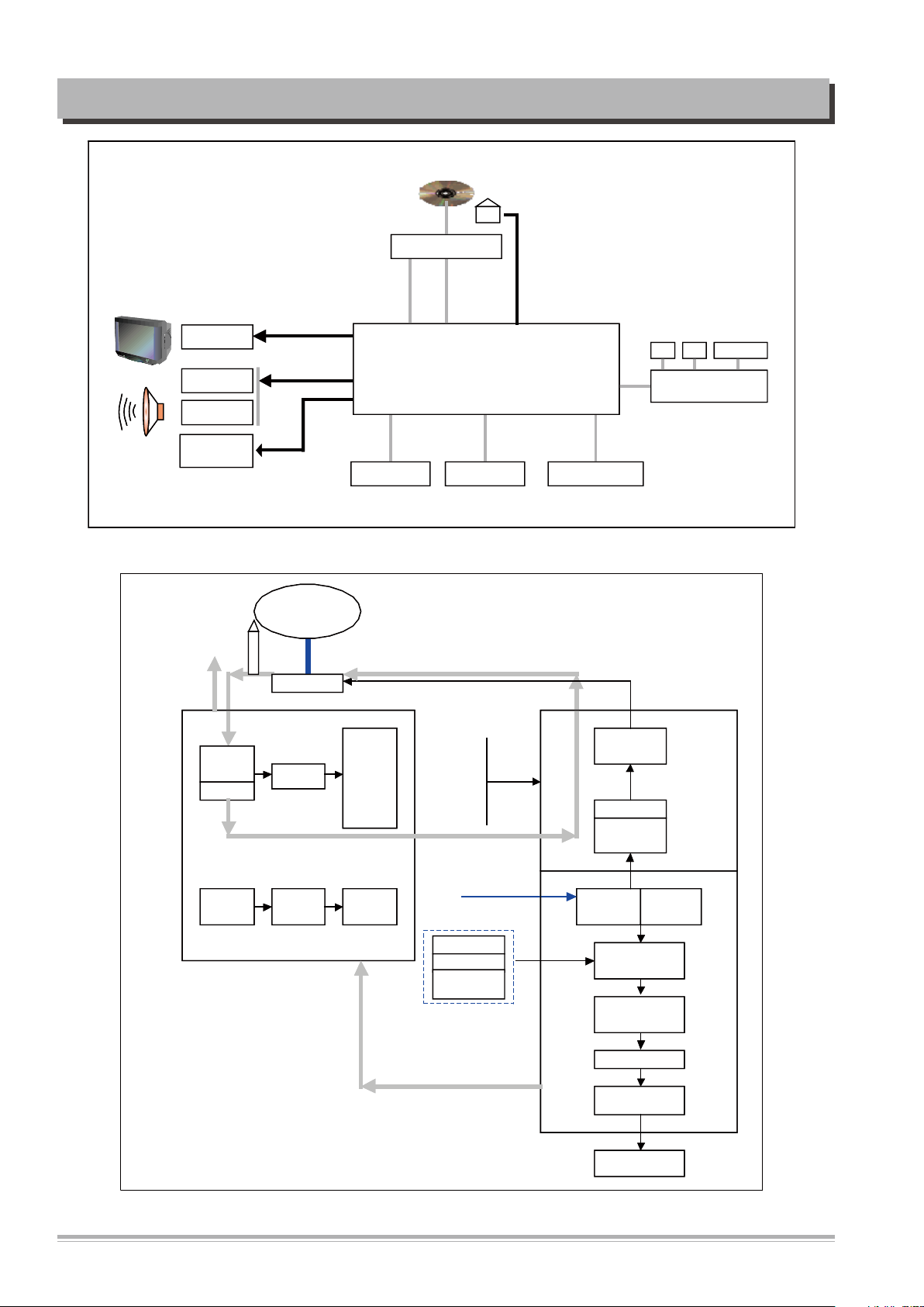
1. DVD Module
1) Summary
DVD One Board consists of: Loader part that reads and transmits audio and video data saved
at Optic Discs (DVD, CD-DA, VCD, CD-R) to MPEG Decoder part; MPEG Decoder part, which,
by decoding and encoding data received from the Loader, produces analog signals; and u-Com
that controls the overall system including the loader and MPEG decoder.
2) How Does it Operate
Insert the power cord and then power transmitted to each IC, and the SET will be the STANDBY status which requires the least power for input the front panel key, input the STAND BY/
ON key, extinguished the LED. Once the Power On key is entered, u-Com recognizes it and
initiates each chipset, performs sequential algorithms such as determining whether the disc
is in or not, and if in, what type of disc is loaded.
Through this process, it can read disc data before transmitting it to the MPEG Decoder. The
MPEG Decoder will then decode and encode such data before generating the final analog
audio and video signal outputs.
DVD-MODULE Block Diagram
3
CIRCUIT OPERATIONAL DESCRIPTIONCIRCUIT OPERATIONAL DESCRIPTION
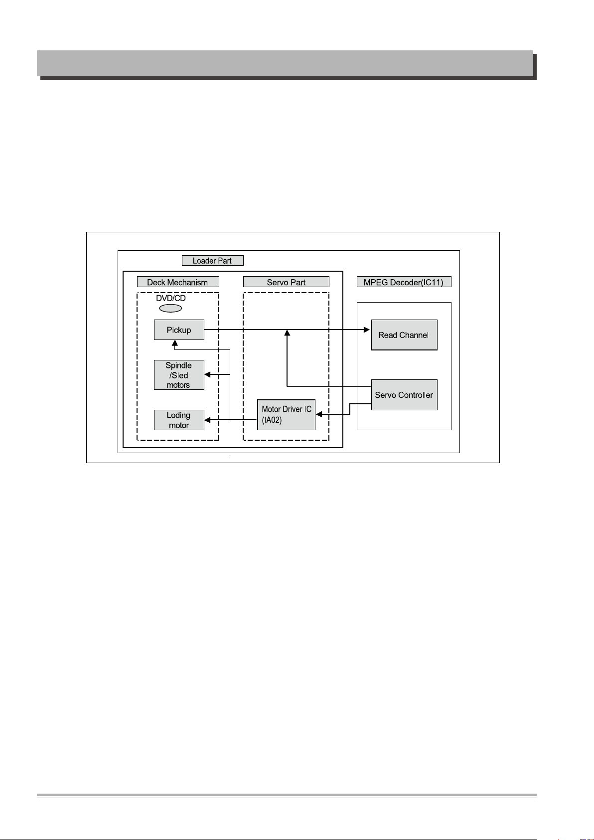
3) Loader Part
The loader which read the data of audio/video from optic disc and transfer them to MPEG
decoder can be divided into Deck total DVD assay(in a short term, Mecha) and Servo. Mecha
mounts with the optical pick-up which allows reading the signal of a disc using laser beam
and makes it operates and consists of the deck mechanism which allows loading a disc and
reading the data. Servo is a sort of circuit which allows operating the loader and recovering
the data and consists of Motor Drive IC operating the spindle, the sled, the loading motor.
Loader Block Diagram
4
CIRCUIT OPERATIONAL DESCRIPTION
M
M
DISC
SPINDLE
MOTOR
LOADING
MOTOR
DECK MECHANISM
DVD : A,B,C,D,RF
CD : A,B,C,D,E,F,RF
PD,PREF
PICK
UP
KEY Input
B/Pb
IC101
29LV800
8M
FLASH ROM
FDA[0:20]
NSOE
NSCSO
NSWE
MDB[00:15]
L
CVBS
R/PrG/Y
R
Y
C
L/R
-12V
AC 90V~240V
50HZ/60Hz
+12V
D5V
3.3V
27MHz
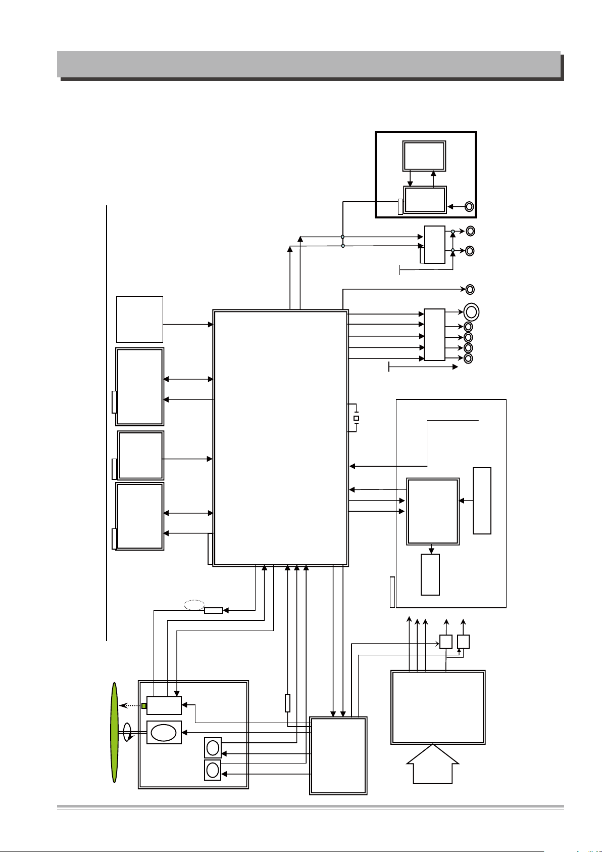
S5L5008 DVD-PLAYER OVERALL BLOCK DIAGRAM
D5V
IC304
4558
OP-AMP
LOAD[+,-]
FCS[+,-]
TRK[+,-]
SPN [+,-]
SLED
(FEEDING)
MOTOR
SLD[+,-]
M
3.3V
1.2V/3.3V
Q5~Q9,Q15
VIDEO BUFFER
SPDF_R
RGB_SW
MODE1
MODE2
CDLD,DVDLD,
SSTOP
OPEN_SW,CLOSE_SW
FDB[0:7]
U1
6928
POWER
BOARD
VSTB
MUTE
IC104
32M 16BIT
SDRAM
MMSD416T216
SDRAM_3.3V
MDA[00:11]
DCLK
CKE
BA0
BA1
DQM
NDWE
NCAS
NRAS
IC100
SAMSUNG S5L5008
+-12V
OPEN, CLOSE,SLD_PWM,FOD
CD/DVD_SW, VR_CD,VR_DVD
CD/DVD
SPD_SENSE
CON5
UART
Download
UART_RXD,TXD
Q14
1.2V
IC1
AT5669
Motor Drive
LED DISPLAY
RF+MPEG IC
Q13
CVBS
R/Pr G/ Y B/Pb
Y
C
Q100
C108,D100
NSYS_RESET
REMOTE
FRONT CONTROL BOARD
VSCK
VSDA
TRB2
TRB1
SPD_PWM,TRD,DR_MUTE,VREF
+5V
3.3V
AL,AR
IR
MIC
U2
4558
AMP
U1
2399
ECHO
MIC
+12V
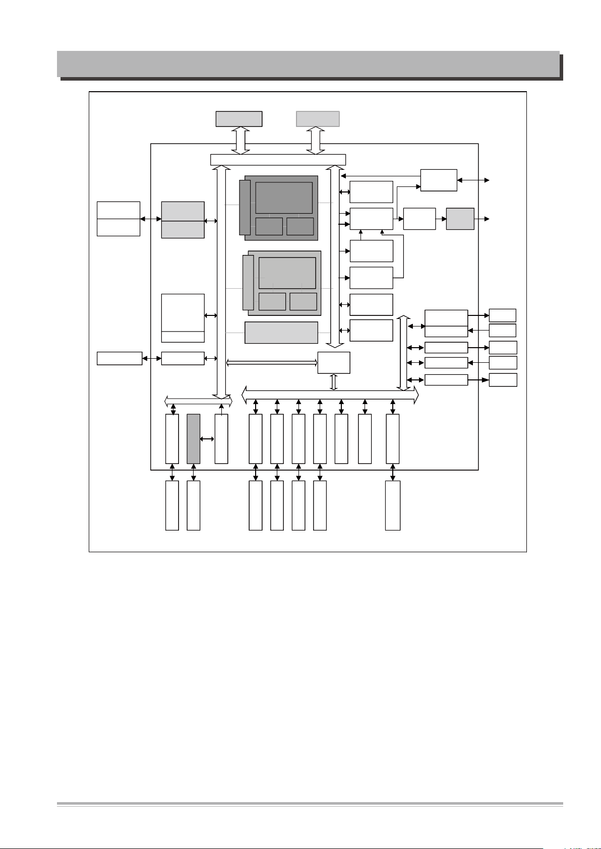
2. Overall Block Diagram--S5L5008(2CH)
1) 2CH
5

CIRCUIT OPERATIONAL DESCRIPTION
3. MPEG Decoder
The signal read from DVD disc is output into the RF signal and Servo related signal through
the RF IC and they are input into the MPEG decoder and processed the MPEG decoding
and divided into video/audio signal. The video signal is output into the analog audio signal
through the built-in encoder block and also the audio signal into the audio DAC through the
audio decoder block.
MPEG decoder consists of existing MPEG-2 decoder and single chip combined the digital signal processing part which is the core technology of DVD player with the Servo controller.
1) DVD Servo And MPEG-2 Decoder : S5L5008
SAMSUNG S5L5008 DVD SoC is designed to provide a cost-effective, low power size
and high performance DVD players solution for DVD-Video, DVD-Audio & many of CD
applications. To reduce total system cost, S5L5008 also providesthe following features:
a Optical RF,a front-end controller, a back-end decoder, a control CPU with separate
4KB Instruction and 4KB Data Cache, an improved audio DSP, a programmable video
encoder with a dual output capability of interlaced and progressive scan, Memory controller, 4-channel Timers with PWM, I/O Ports, 1-channel 10-bit ADCsfor Servo control,
5-channel 10-bitVideo-DACs, 1-channel UART with handshake, IIC-BUS interface, IISBUS interface, SIO, 6-in-1 Card Interface, SPDIF in/out, Audio PWM outand PLL for
clock generation.
The S5L5008 is fabricated in a standard 0.13um CMOS technology. Its low-power, sim
ple, elegant and fully static design is particularly suitable for cost-sensitive and powersensitive applications.
The S5L5008 is built around the outstanding CPU core: The ARM946E-S cached processor is a member of the ARM9 Thumb family of high-performance 32-bit system-ona-chip processor solutions. It provides a complete high performance CPU subsystem,
including ARM9TDMI RISC integer CPU, 4KB instruction/data caches, write buffer,
and protection unit, with an AMBA bus interface. The ARM9TDMI core within the
ARM946E-S executes both the 32-bit ARM and 16-bit Thumb instruction sets, allowing
the user to trade off between high performance and high code density. It is binary compatible with ARM7TDMI, ARM10TDMI, and StrongARM processors, and is supported by
a wide range of tools, operating systems, and application software.
-
6
CIRCUIT OPERATIONAL DESCRIPTION
I2C
IR
UART
GPIO
16 bit Timers
WDT
CLKRST_GEN
PLLs
JTAG
PC debugger
Ext INT/
User IF
SPDIF
Master
XTL
Debugger
32-bit APB
32-bit AHBs
MPEG
Video
Decoder
Bus
Bridge
Sub-picture
Decoder
NTSC
/PAL
Encoder
MIU/Arbiter
Video
Processor
( Scaling )
Video
5-DAC
32-bit AHBs
OSD/Mixer
CSS
MPEG
Stream
DEMUX
Decoder
32-bit APB
SPDIF OUT
I2S_In
Servo/DP
AFE
EPROM
SPI
2D Graphic
Engine(GA)
Video
Output
Audio
Interface
CCIR656
Interface
RemoCon
ARM946E-S
(processor core)
4KB
I-cache
4KB
D-cache
BUS Interface
Motor/
Driver
CalmADM
( Audio DSP )
8KB
I-cache
12KB
D-cache
BUS Interface
I2S_Out
(5x)
16
4Mb Flash
8
Host IF/VFD
OPU
Mic
ATAPIDevice Drive
SPDIF IN
Audio
DACs
SPDIF
Slave
16Mb SDR
Audio
AMP
Audio PWM
Reverse
playback
DRAM
5Mbit
S5L5008 Block Diagram
7
CIRCUIT OPERATIONAL DESCRIPTION
Deck Mechanism
P/U
S5L5008X(DVDP SOC)
CPU + RF + Servo/DSP +
A/V Decoder + DRAM
2-Ch DAC
5.1-Ch
DAC
Display
SDRAM Flash ROM Peripherals
Front VFD Display
(SPI Interface)
IR
Key
Display
Audio
AMP
VREF(1.6 5V)
FOD
TRD
SLDPWM
SPDPWM
MON (Id le )
Main data
REFEQ
A1
B1
C1
D1
E
F
ABCD AGC Equ al ize
ABCD1
EF
LPF
ENV
ABCD
TE
FE
MIRR
FOKB
PLL DFT
ENV
ABCD(RFO)
TE
FE
DFCT
MIRR
Ana log &
Sl ice
Clo ck
Recovery
EFM
Demo dula tor
ECC
Descramble
& EDC
Frame Sync
Detect
Digita l
Servo
DAC
Core
CLV
SERVO
DP
Command
Motor Control
DISC
FAN8026
Pick Up
FEU
SDRAM
RFSUM
A
B
C
D
LDODVD
PDDVD
LDOCD
RF
ADC
Equ al ize
Viterbi
Decod e
EFM
PLCK
S5L5008 System Diagram(Servo Application)
S5L5008 Servo Control Flow
8
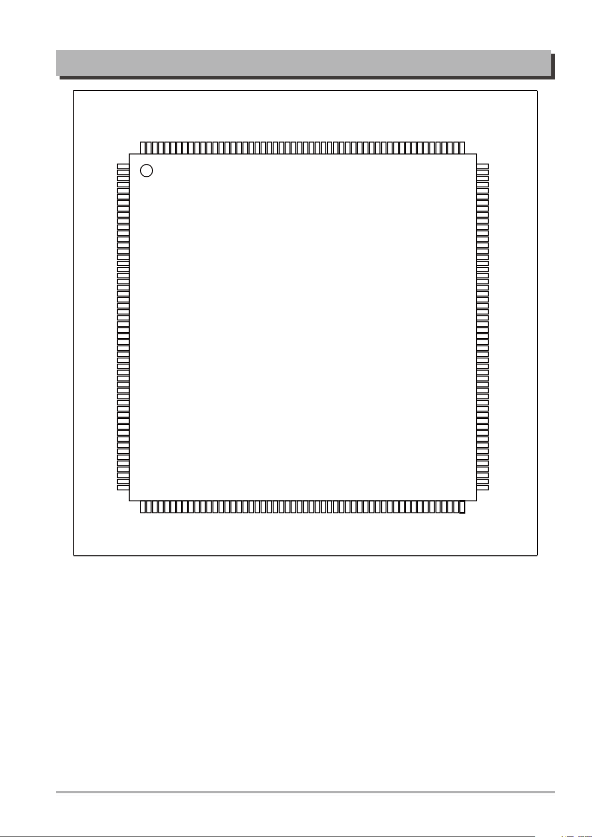
CIRCUIT OPERATIONAL DESCRIPTION
S5L5008
HSYNC(P0.5)
MDB12
VDDP4
VSSP5
MDB3
MDB13
MDB2
MDB14
MDB1
MDB15
VDDC2
VSSC2
MDB0
VSSP6
NTPST(P0.0)
VDD5
VDDC3
VSSC3
TDI(P0.1)
TCK(P0.2)
TMS(P0.3)
TDO(P0.4)
VSYNC(P0.6)
BTCLK(P0.7)
DACVDD33R
VREFOUT
CCOMP
IRESET
DACVSS33R
DACVBB33A
DAC0
DAC1
DAC2
DACVSS33A
DACVDD33A
DAC3
DAC4
DACVDD33D
DACVSS33D
PWMVSS3
I2SDO4(P2.4)
I2SDO3(P2.3)
PWMVDD33
I2SDO2(P2.2)
I2SDO1(P2.1)
I2SDO0(P2.0)
VDDC4
VSSC4
I2SMCLK(P2.5)
I2SWSO(P2.6)
12SBCKO(P2.7)
I2CCK(P1.1)
I2CDAT(P1.2)
I2SDI(P1.0)
55
5657585960
61
62
636465666768697071
72
737475
7677787980818283848586
87
88
89
90
919293
94
95
96
97
98
99
100
101
102
103
104
105
106
107
108
216
215
214
213
212
211
210
209
208
207
204
205
204
203
202
201
200
199
198
197
196
195
194
193
192
191
190
189
188
187
186
185
184
183
182
181
180
179
178
177
176
175
174
173
172
171
170
169
168
167
166
165
164
163
1
2
3
4
5
6
7
8
9
10
11
12
13
14
15
16
17
18
19
20
21
22
23
24
25
26
27
28
29
30
31
32
33
34
35
36
37
38
39
40
41
42
43
44
45
46
47
48
49
50
51
52
53
54
FDA12(P5.3)
FDA13(P5.2)
FDA14(P5.4)
FDA15(P5.5)
FDA16(P5.6)
FDA19(P6.1)
VSSP9
VDDP8
EDRVSSA
EDRVCCA12
EDRVSSQ
EDRVPP33V
EDRVSSP
EDRVSSP12
FDB7(P7.1)
FDB6(P7.0)
FDB5(P6.7)
FDB4(P6.6)
FDB3(P6.5)
FDB2(P6.4)
FDB1(P6.3)
FDB0(P6.2)
NSOE
NSWE
NSCS0
FDA0(P3.6)
VSSC6
VDDC6
VSSP8
VDDP7
RXD(P3.5)
TXD(P3.4)
VSSC5
VDDC5
SPICLK(P3.3)
MISO(P3.2)
MOSO(P3.1)
IRIN(P3.0)
TDIADM(P1.6)
TCKDAM(P1.5)
TMSADM(P1.4)
NTRSTADM(P1.3)
NRESET
SPDP
SLDP
VSSSVO33A
TEO
FEO
TZCI
TE
VREF
RBIAS
PREF
FCB
162
161
160
159
158
157
156
155
154
153
152
151
150
149
148
147
146
145
144
143
142
141
140
139
138
137
136
135
134
133
132
131
130
129
128
127
126
125
124
123
122
121
120
119
118
117
116
115
114
113
112
111
110
109
MPEI
ABCDO
MPEO
MCB
MCP
VDDSVO33A
PDDVD
LDOCD
LDODVD
F
E
D
C
B
A
D1
C1
B1
A1
MIRRI
ABCDI
RFSUM
VSSEQ33A
RFAGC0
AGCP
AGCB
AGCACN
AGCACP
AGCC
RFEQ0
VDDEQ33A
EFMI
VDDPLS33A
VSSPLS33A
MCHL
MCHR
ADCVDD33A
ADCVSS33A
DPLLVSS12A
LFCDPLL
LFDVDPLL
VCTLCD
VCTLDVD
DPLLVDD12A
PLLVDD12
PLL1FLT
PLL1VSS12
PLL0VDD12
PLL0FLT
PLL0VSS12
XI
XO
VSSP7
VDDP6
FDA11(P5.1)
FDA10(P5.0)
FDA9(P4.7)
FDA8(P4.6)
FDA18(P6.0)
FDA17(P5.7)
FDA7(P4.5)
FDA6(P4.4)
VDDP0
VSSP0
VSSP1
FDA1(P3.7)
MDA4
MDA3
VDDC0
VSSC0
MDA5
MDA2
MDA6
MDA1
VDDP1
MDA7
MDA0
VSSP2
MDA8
MDA10
MDA9
MDA11
BA0
BA1_NDCS1
VDDP2
NDCS0
VSSP3
NRAS
DCLK
NCAS
VDDC1
VSSC1
NDWE
DQM
MDBB
VDDP3
MDB7
VSSP4
MDB9
MDB6
MDB10
MDB5
MDB11
MDB4
FDA5(P4.3)
FDA4(P4.2)
FDA3(P4.1)
FDA2(P4.0)
S5L5008 Pin Assignments (216-QFP)
9

CIRCUIT OPERATIONAL DESCRIPTION
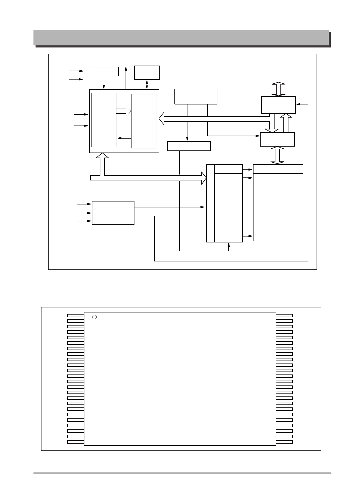
2) Flash Memory : ES29LV800DB-70TG
Description
The ES29LV800 is a 8 megabit, 3.0 volt-only flash memory device, organized as 1M
x 8 bits (Byte mode) or 512K x 16 bits (Word mode) which is configurable by BYTE#.
Four boot sectors and fifteen main sectors are provided : 16Kbytes x 1, 8Kbytes x 2,
32Kbytes x 1 and 64Kbytes x 15. The device is manufactured with ESI’s proprietary,
high performance and highly reliable 0.18um CMOS flash technology. The device can
be programmed or erased in-system with standard 3.0 Volt Vcc supply ( 2.7V-3.6V) and
can also be programmed in standard EPROM programmers. The device offers minimum
endurance of 100,000 program/erase cycles and more than 10 years of data retention.
The ES29LV800 offers access time as fast as 70ns or 90ns, allowing operation of highspeed microprocessors without wait states. Three separate control pins are provided to
eliminate bus contention : chip enable (CE#), write enable (WE#) and output enable
(OE#).
All program and erase operation are automatically and internally performed and controlled by embedded program/erase algorithms built in the device. The device automatically generates and times the necessary high-voltage pulses to be applied to the cells,
performs the verification, and counts the number of sequences. Some status bits (DQ7,
DQ6 and DQ5) read by data# polling or toggling between consecutive read cycles provide to the users the internal status of program/erase operation: whether it is successfully done or still being progressed.
The ES29LV800 is completely compatible with the JEDEC standard command set of single power supply Flash. Commands are written to the internal command register using
standard write timings of microprocessor and data can be read out from the cell array
in the device with the same way as used in other EPROM or flash devices.
10
CIRCUIT OPERATIONAL DESCRIPTION
A15
A14
A13
A12
A11
A10
A9
A8
NC
NC
WE#
RESET#
NC
NC
RY/BY#
A18
A17
A7
A6
A5
A4
A3
A2
A1
A16
BYTE#
Vss
DQ15/A-1
DQ7
DQ14
DQ6
DQ13
DQ5
DQ12
DQ4
Vcc
DQ11
DQ3
DQ10
DQ2
DQ9
DQ1
DQ8
DQ0
OE#
Vss
CE#
A0
1
2
3
4
5
6
7
8
9
10
11
12
13
14
15
16
17
18
19
20
21
22
23
24
48
47
46
45
44
43
42
41
40
39
38
37
36
35
34
33
32
31
30
29
28
27
26
25
48-Pin Standard TSOP
ES29LV800
Command
Register
Analog Bias
Generator
Address Latch
BYTE#
CE#
OE#
A<0:18>
RESET#
Vcc
Vss
Chip Enable
Output Enable
Logic
Vcc Detector
Timer/
Counter
Y-Decoder
X-Decoder
Y-Decoder
Cell Array
Data Latch/
Sense Amps
Input/Output
Buffers
Sector Switches
DQ0-DQ15(A-1)
RY/BY#
Write
State
Machine
WE#
FLASH ES29LV800 Block Diagram
FLASH ES29LV800 Pin Assignments
11
CIRCUIT OPERATIONAL DESCRIPTION
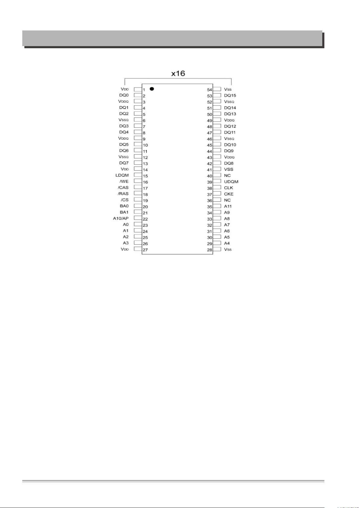
3) SDRAM : MMSD416T216-O
SDROM MMSD416T216-O Pin Assignments
12
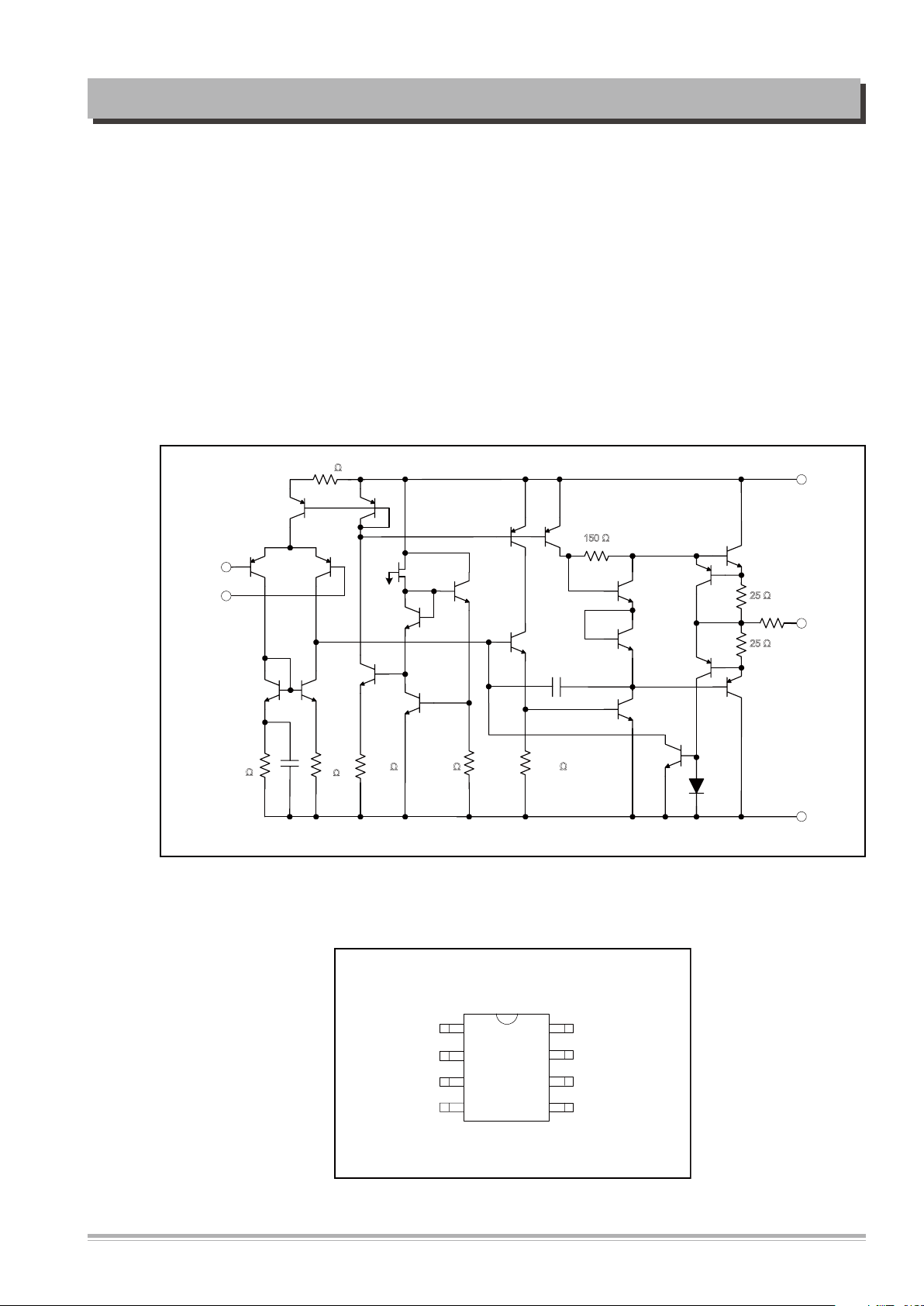
4) AMPLIFIERS : AZ4558CM-E1
- Input
+ Input
3.1 KΩ
7.1
KΩ
7.1
KΩ
87
pF
480 Ω
4.2 KΩ
36 KΩ
150 Ω
10pF
25 Ω
25 Ω
V
EE
Output
V
CC
(SOIC-8/DIP-8)
Top View
8 V
CC
7 OUTPUT 2
6 INPUT 2-
5 INPUT 2+
1
2
3
4
OUTPUT 1
INPUT 1-
INPUT 1+
V
EE
M Package/P Package
Description
The AZ4558 consists of two high performance operational amplifiers. The IC features
high gain, high input resistance, excellent channel separation, wide range of operating
voltage and internal frequency compensation. It can work with ± 18V maximum power
supply voltage.
The AZ4558 is specifically suitable for applications in differential-in, differential-out as
well as in potentialmetric amplifiers and where gain and phase matched channels are
mandatory.
The AZ4558 is available in DIP-8 and SOIC-8 pack-age.
CIRCUIT OPERATIONAL DESCRIPTION
AMPLIFIERS AZ4558CM-E1 Block Diagram
AMPLIFIERS AZ4558CM-E1 Pin Assignments
13
CIRCUIT OPERATIONAL DESCRIPTION
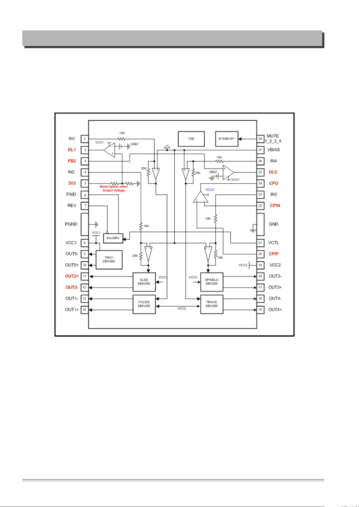
5) Motor Drive IC: AT5669
The AT5669 is a 5-channel BTL driver IC. Two of them can drive DC motors and two can drive
coils, such as the focus and tracking actuators of a CD-ROM/DVD-ROM/DVD-Player system It
also built-in one channel bi-direction DC motor driver for Tray. Using the built-in linear regulator, it can be save the PCB space. It also includes 1 comparator.
Motor Drive IC (AT5669) Block Diagram
14
 Loading...