

Daewoo DCR-9130 Service Manual

S/M No. : VCR9ADPEN0
✔ Caution :
In this Manual, some parts can be changed for improving, their
performance without notice in the parts list. So, if you need the latest
parts information,please refer to PPL(Parts Price List) in Service
Information Center (http://svc.dwe.co.kr).
DAEWOO ELECTRONICS Corp.
Dec., 2003
http : //svc.dwe.co.kr
Service Manual
DVD COMBO RECEIVER
MODEL :
DCR-9130 SERIES

1
SPECIFICATIONS...............................................................................................................2
ADVANTAGES OF THIS PRODUCT....................................................................................3
TROUBLE SHOOTING....................................................................................................................5
WAVEFORMS................................................................................................................................31
CIRCUIT DIAGRAM.......................................................................................................................35
PCB CIRCUIT BOARD..................................................................................................................43
INSTRUMENT DISASSEMBLY.....................................................................................................47
ELECTRICAL PARTSLIST............................................................................................................53
CONTENTS
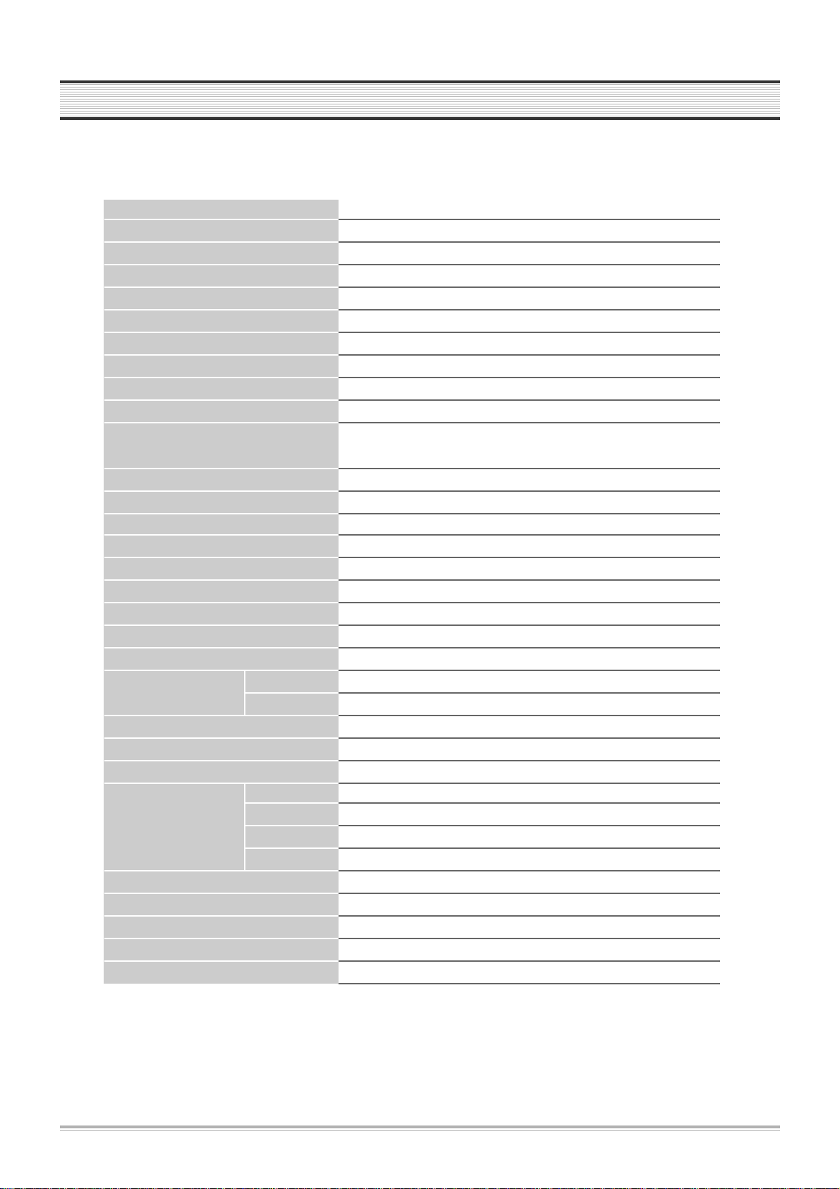
2
SPECIFICATIONS
Power 200-240V~ AC 50/60Hz
Consumed electricity 75W
Weight 7.15kg
Dimension (WxHxD) 430mm x 91mm x 370mm
Operative temperature +5¡C~40¡C
Installation condition Horizontal / Relative humidity under 80%
Signal type PAL COLOR
Antenna Input/output U/V-mixed: 75W unbalanced
VIDEO input 1.0 Vp-p unbalanced, RCA JACK
AUDIO input -8.8dBm, RCA JACK
VIDEO output VIDEO output terminal, 1.0 Vp-p unbalanced, SCART
RGB output (75W In load R: 0.7Vp-p, G: 0.7Vp-p, B: 0.7Vp-p,)
AUDIO output Audio output terminal: -5.8dBm(VCR), 2.0Vrms(DVD), SCART
Playable tape Very high dense tapes with VHS marks
Playable disc DVD, VIDEO-CD, CD (12cm), CD (8cm), MP3, CD-R, CD-RW
Tape speed SP:23.39 mm/s, LP: 11.70 mm/s
Playtime SP: 3hrs, LP: 6hrs (use of E-180 tape)
Clock display 24hrs
Time Recording 8 programs a month
Persistence in power failure 1 min
VIDEO S/N (VCR) Over 43dB(Standard recording)
Resolution VCR Over 240 lines (Standard recording)
DVD Over 400 lines (DVD Disc PLAY)
AUDIO (VCR) Over 65dB (Hi-Fi), over 40dB (Mono)
AUDIO (DVD) 90dB
AUDIO dynamic range 90dB
Speaker Output Center 50W (6W) (240 x 115 x 115)
(Impedance) & (Size) Front L/R 50W x 2 (6W) (140 x 115 x 200)
Rear L/R 50W x 2 (6W ) (108 x 88 x 164)
Subwoofer 50W (6W ) (198 x 350 x 355)
Amp Frequency Response 20Hz ~ 20KHz
Radio Tuning Range FM : 87.5 ~ 108.0 MHz, AM : 522 ~ 1611KHz
Radio Intermediate Freq. FM : 10.7 MHz, AM : 450 KHz
FM Antenna Impedance 75 W (unbalance)
AM Loop Antenna Inductance 12.5 uH (1KHz)

ADVANTAGES OF THIS PRODUCT
3
¥ DVD, VCD, CD, CD-R(MP3), CD-RW, VHS playback function
¥ Watching DVD for recording broadcast
¥ Integrated remote control (VCR, DVD)
¥ VISS function (VHS Index Search System)
¥ Multiplex sound playback/record
¥ High Sound Quality of 6 head Hi-Fi (Hi-Fi Model only)
¥ One Touch timer Recording (OTR)
¥ MP3 file playback function (CD-R disc having records of MP3 files)
¥ GUI (Graphical User Interface) OSD (On Screen Display)
By using the [DISPLAY] button on the remote control, information on the DVD/VCD/CD player and disc, can be displayed on
the TV screen.
¥ Screensaver function (DVD)
¥ Digital Amplification total output power 300W
¥ 50W X 5 satellite speaker system plus 50W Subwoofer
¥ Dolby Digital, Dolby prologic, Dolby Prologic II, DTS compatible
¥ Various Sound Field effect (Movie, Music, PL EMUL, Matrix, Classic, Hall, Theater)
¥ High bit / high sampling with 27MHz / 10bit video encoder
This unit has 27MHz / 10bit capability, that enables the faithful reproduction of fine images.
¥ High bit / high sampling with 96KHz / 24bit audio D/A converter
With this 96KHz / 24bit linear Pulse Code Modulated signals, which constitute the highest specifications in the DVD standards,
you can enjoy faithfully reproduced sound in all of its various modes. To support 96KHz sampling / 24bit sound, the shaping
noise of this multi-level digital sigma type of D/A converter is kept flat up to 44KHz, thus preventing the important audio signals
from being affected.
¥ Built-in Dolby Digital decoder (DVD)
¥ Slow Forward / Reverse (DVD) playback
¥ Fast Forward / Reverse playback
¥ Search of title, chapter, and time in DVD disc, and search of track and time in VCD and CD
¥ Various TV aspect (DVD)
4:3 for Pan and Scan, 4:3 for Letter Box, and 16:9 for Wide
¥ Repeat playback (title and chapter for DVD, track and disc for VCD/CD)
¥ Repeat a defined period from A to B (DVD/VCD/CD)

4
ADVANTAGES OF THIS PRODUCT
¥ Selective Play (DVD/VCD/CD)
You can select and play the desired title / chapter of DVD and track of Video CD/CD in STOP mode.
¥ Various languages OSD (On Screen Display) function (DVD)
You can select and display OSD among various languages. (9 Languages)
¥ Parental Lock function (DVD)
This function can prevent playback of software that may be unsuitable for children.
¥ Multi Audio function (DVD)
The audio soundtrack can be heard in up to 9 languages. In the case of SVCD or VCD, it depends on the disc. (The
number of audio languages depends on the software.)
¥ Multi Subtitle function (DVD)
The subtitle can be seen in up to 9 languages. In the case of SVCD or VCD, it depends on the disc. (The number of subtitle
languages depends on the software.)
¥ Multi Angle function (DVD)
This function allows you to choose the viewing angle of scenes which were shot from a number of different angles. (The
number of angles depends on the software.)
¥ Screen zoom function (DVD/VCD)
¥ Radio function
Digital FM/AM tuner with 50 station memories
¥ RDS (Radio Data System) function
Besides listening the radio, this set can receive the radio channel that sends the letter data and display them on the Display
window. It calls RDS.
5
TROUBLESHOOTING
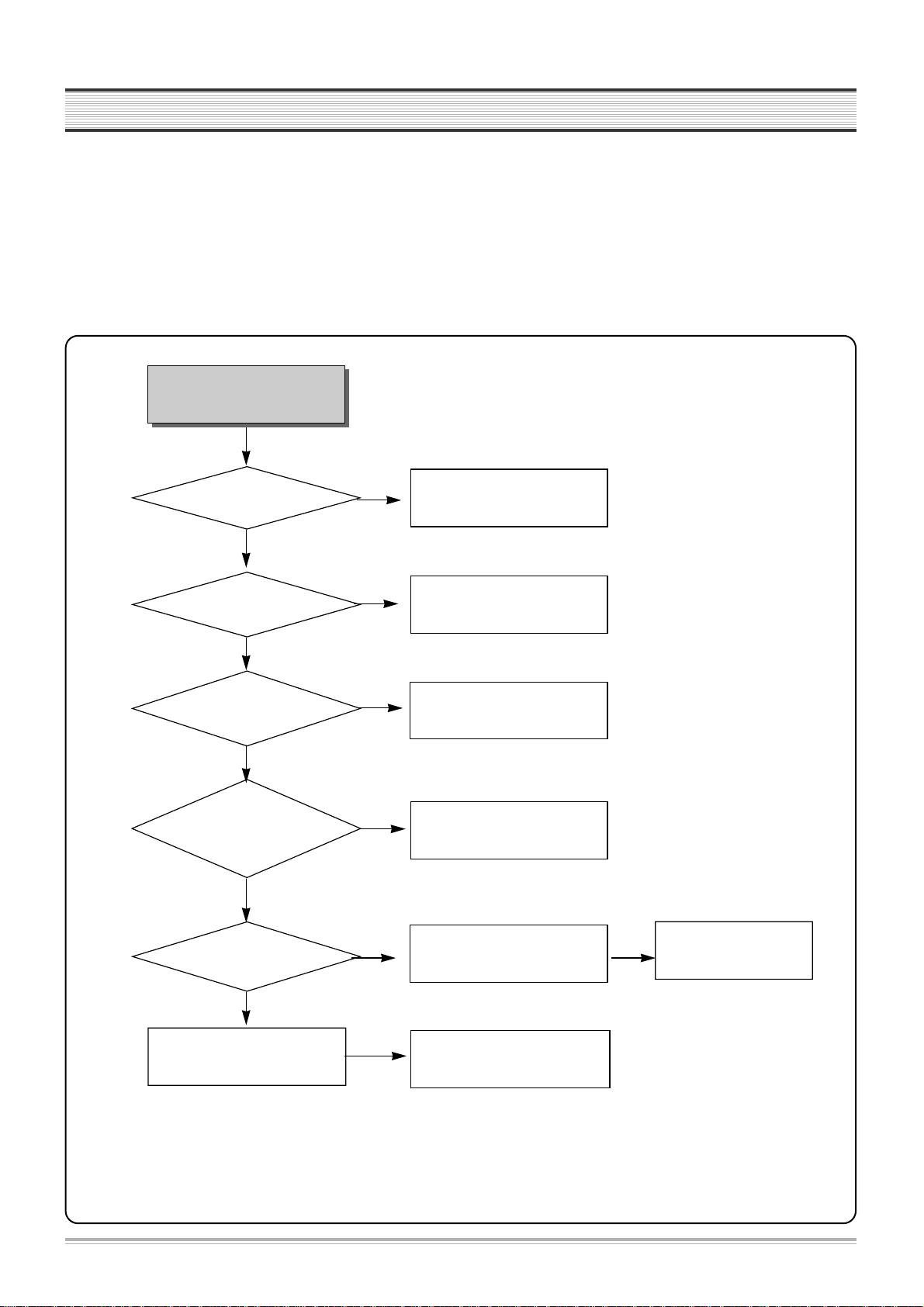
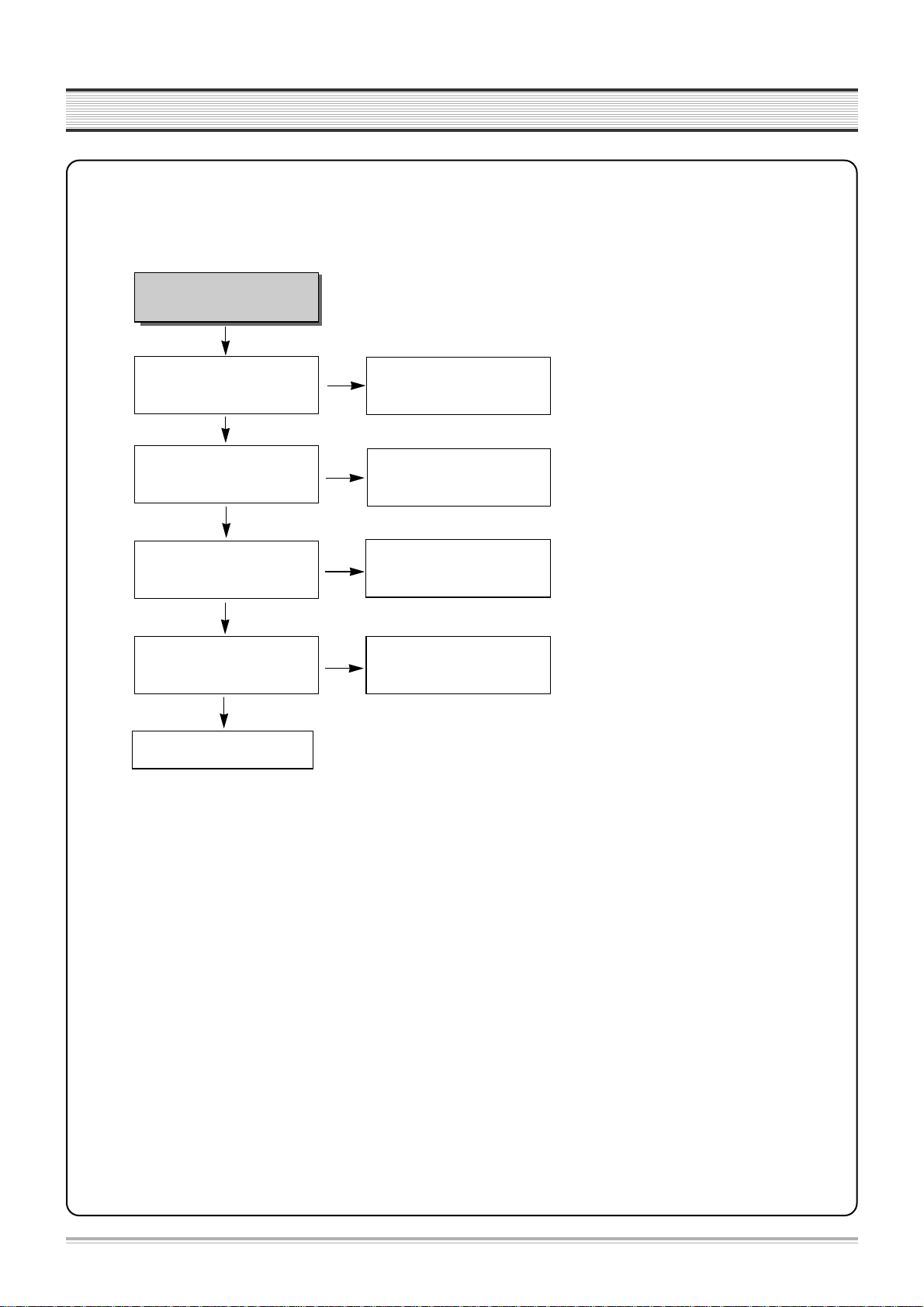
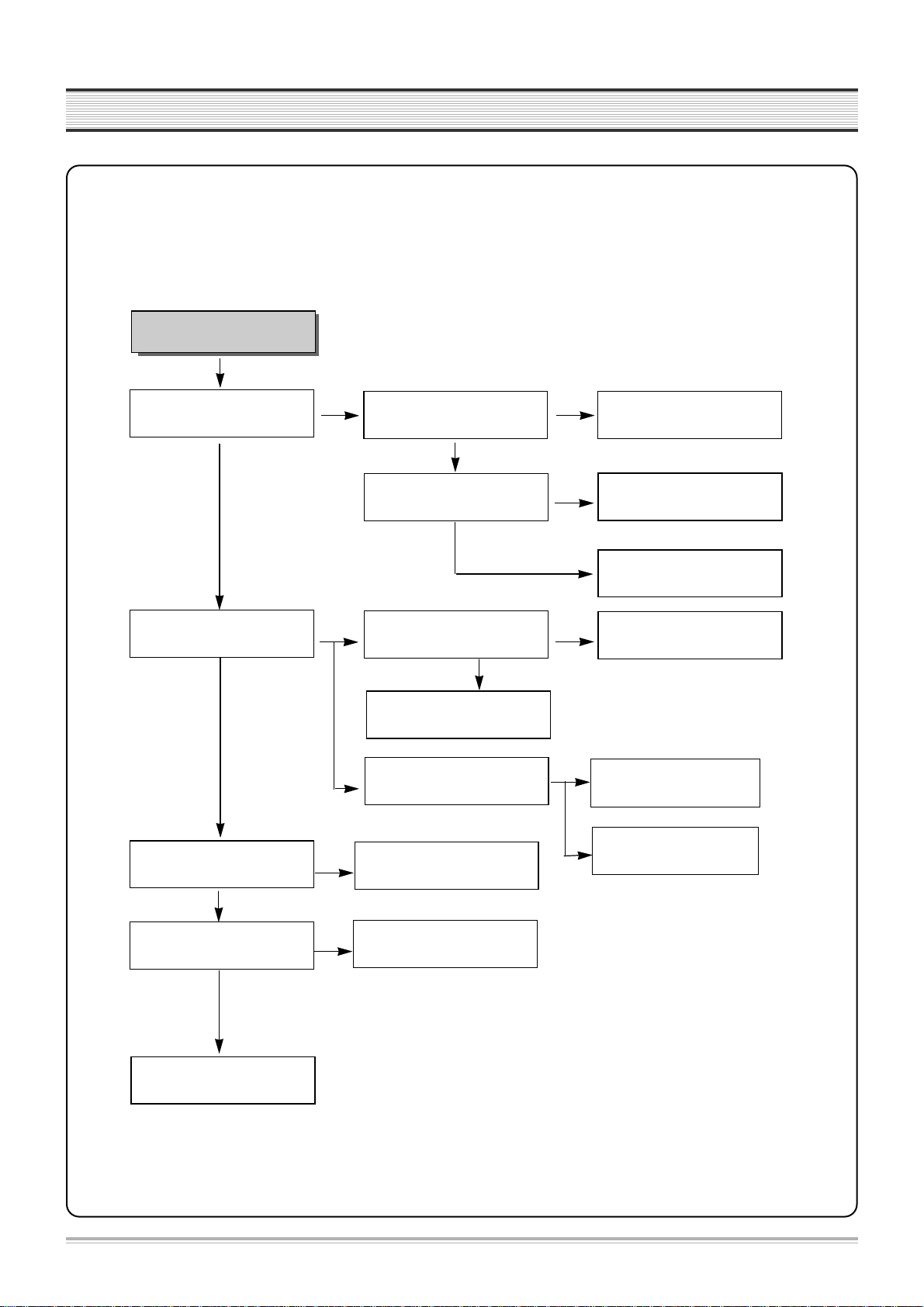
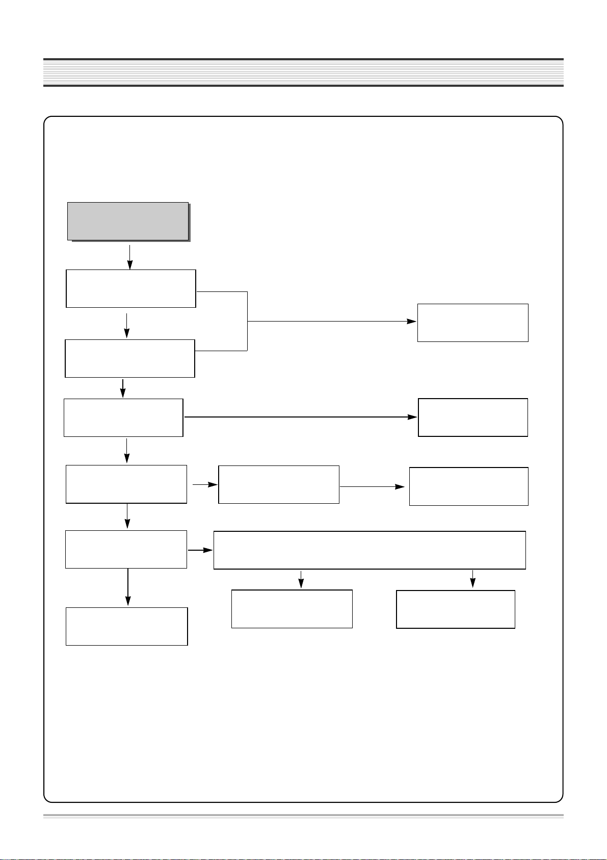
1. POWER CIRCUIT
✓ CAUTION
You must use insulated transformer during the first part test of POWER circuit.
Check IC801,IC804,D821,
D822,D823,D824,D825,D826,
D827,D828,D830
No power
Power cord is ok?
Is 200V~400V voltage
obtained at C805+?
Switching Pulse of
IC801 and IC804
Drain is normal?
Cathode Voltage of
D821,D822,
D823,D824,D825,D826,D827,
D828,D830 is normal?
Output voltage of Q801,
Q802,IC807 is normal?
Check the MAIN BOARD
Exchange Power cord
Check F801,L801,L802,
D801,R803,R804,R807,R808
Exchage the wicked part
11th pin voltage of P823 is DC 5V
when Power on "H"?
NO
YES
YES
YES
YES
YES
NO
NO
NO
NO
NO
Check MICOM
ON/OFF Control
NO
Check Q801,Q802, IC807
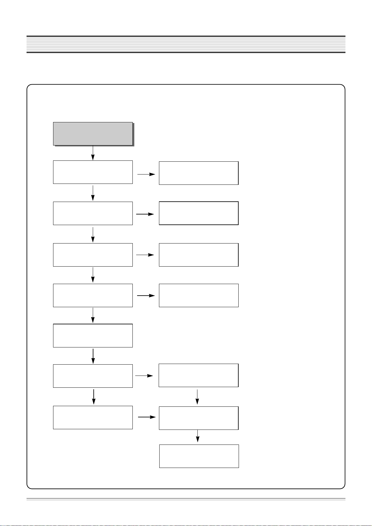
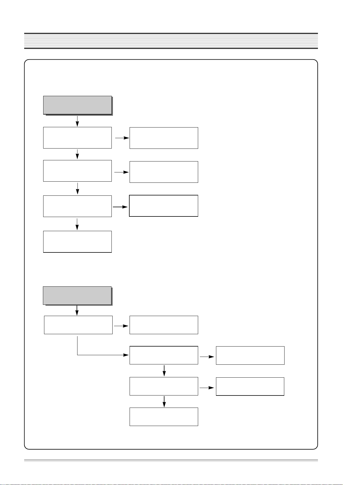
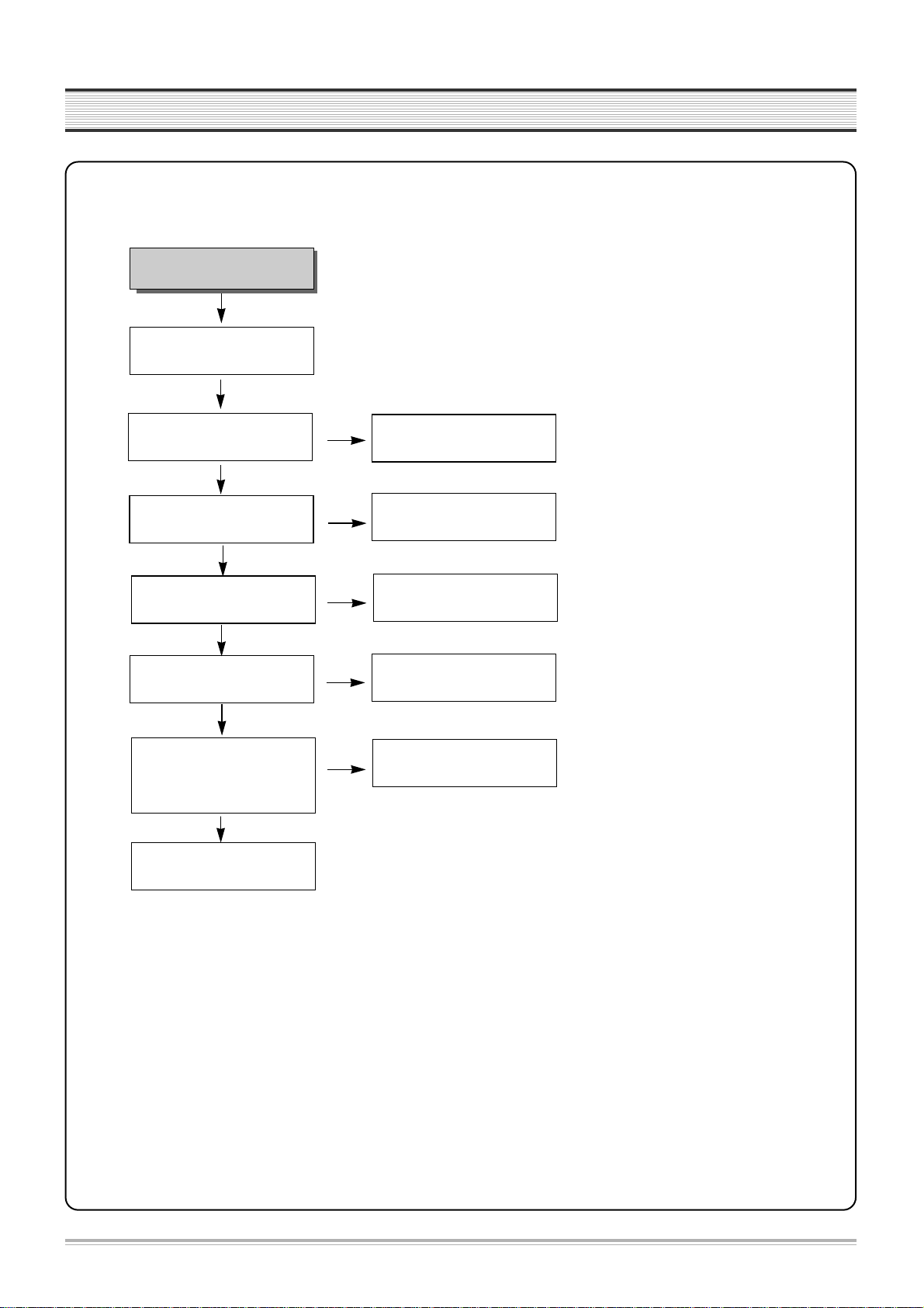
2. SYSTEM CIRCUIT
6
TROUBLESHOOTING
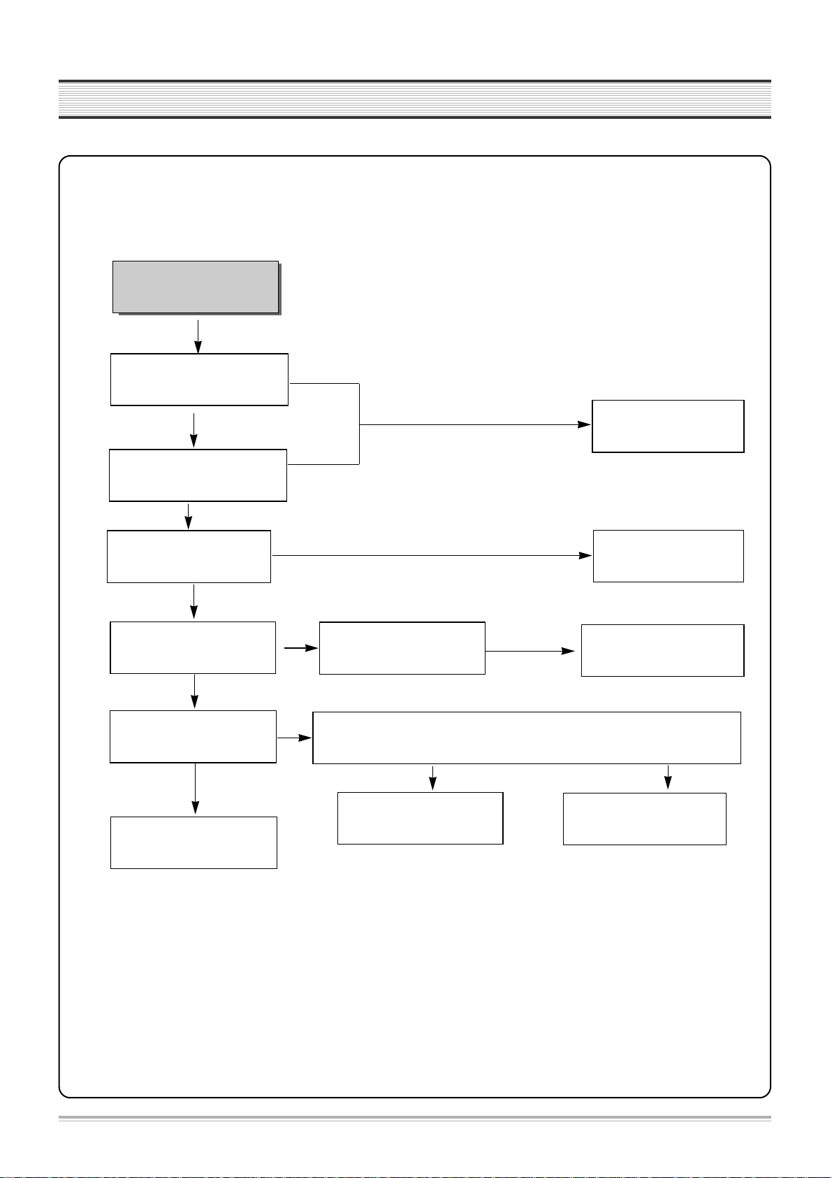
No VFD display.
Is 5V obtained at IC701 pin#13?
Is -24V obtained at IC701 pin#30?
Oscillation at IC701 pin #8?
Is -24V, -20V obtained at F-,
F+?
Specific GRID/SEG doesnt function.
Check D721.
Check POWER circuit at -24V.
Check IC701.
Check IC 701 pin #31~42.
Check IC 701 pin #14~29.
NO
YES
YES
YES
YES
NO
NO
NO
NO
GRID output at PORT of IC701?
YES
SEGoutput at PORT of IC701?
Check POWER circuit at F-, F+.
Exchange IC501.
YES
A. VFD DISPLAY
NO
7
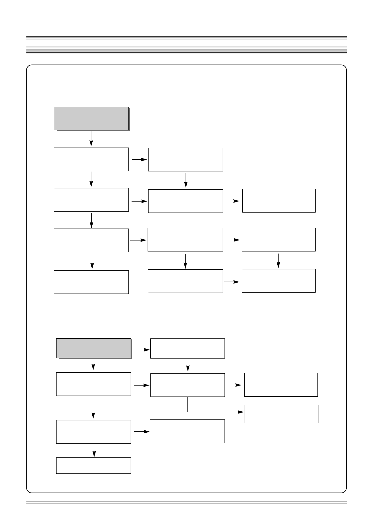
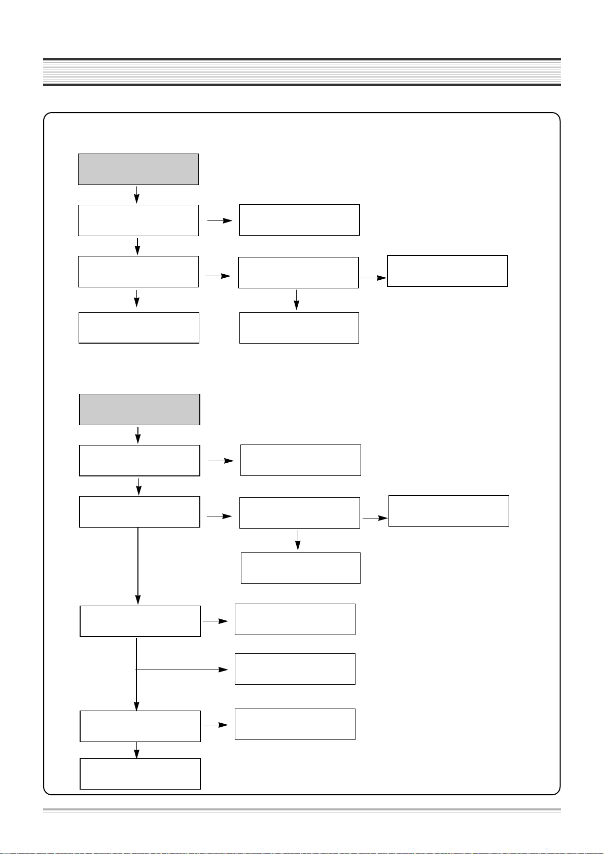
TROUBLESHOOTING
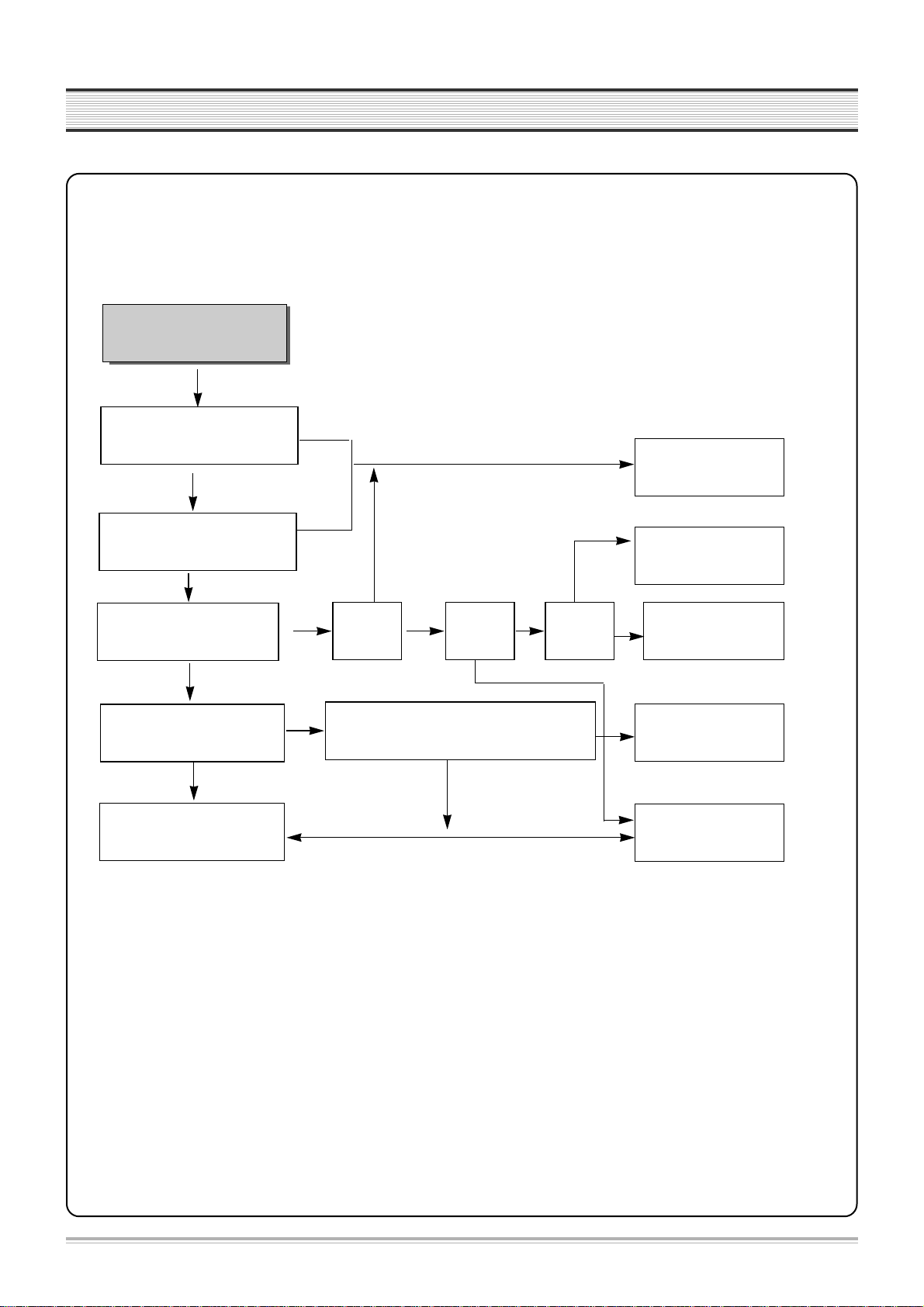
Noise appears on the
playback screen.
Is noise diminished by tracking
adjustment.
Noise band is trembled up and
down?
Re-adjust PATH.
Is the height of CTL HEAD normal?
No dust?
Is there problem in CTL Input
circuit and amplifier.
YES
NO
NO
NO
Is there CTL pulse at IC501
pin#97?
Check IC501.
Noise appears on the screen even
though changing tape.
Re-adjust the height of AC HEAD.
Remove the dust.
Check C510,R545~R547
IC 501 pin #91, 92, 98.
NO
Re-adjust PATH.
B-1. Bad playback quality (1)
YES
YES
YES
YES
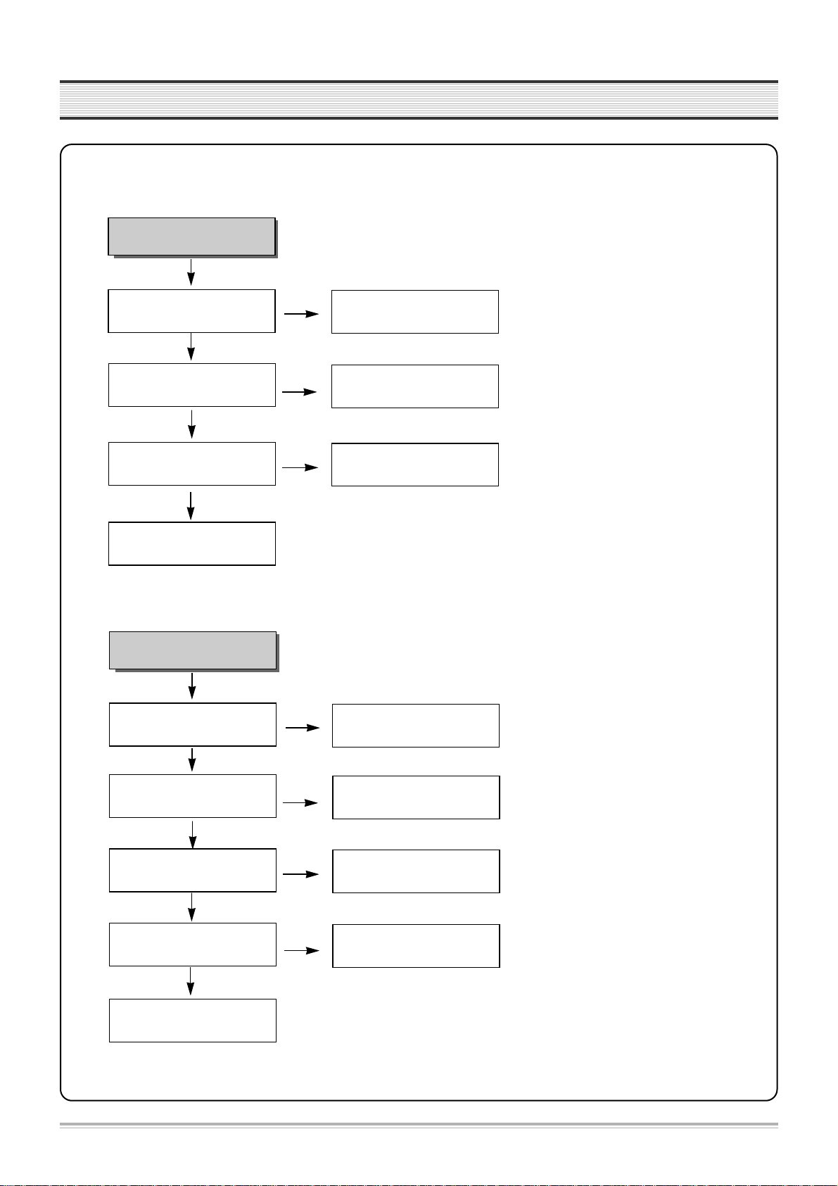
Noise appears on the Full
playback screen.
Are SW pulse and HA SW normal?
Recheck step B-1
(Bad playback quallty (1)).
Check HEAD AMP connector
and HEAD.
YES
YES
NO
NO
ENVE Wave at P502 pin #4?
Check VIDEO circuit.
Are there SW, HA SW pulse at
IC501 pin #16, 18?
Check PCB Pattern.
Check IC501.
B-2. Bad playback quality (2)
YES
NO
YES
8
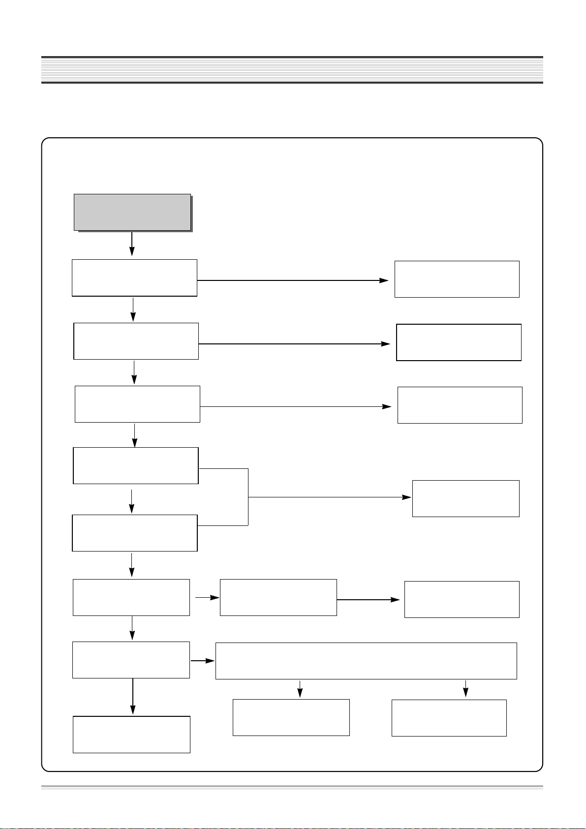
TROUBLESHOOTING
No broadcasting signal
received
Is the output at IC501 pin# 61(CLK),
62 (DATA) normal?
Is SIF,Video output at TMI(RF101)
pin#22,24 normal?
Check IC 501.
Check IC301.
Check IC501.
YES
YES
NO
NO
NO
Is Video Signal input at IC501
pin#50?
Is there Video output at IC501
pin#52?
Check TMI (RF101) Block.
NO
Check Video Buffer Q670, Q671
C. No broadcasting signal received
YES
YES
YES
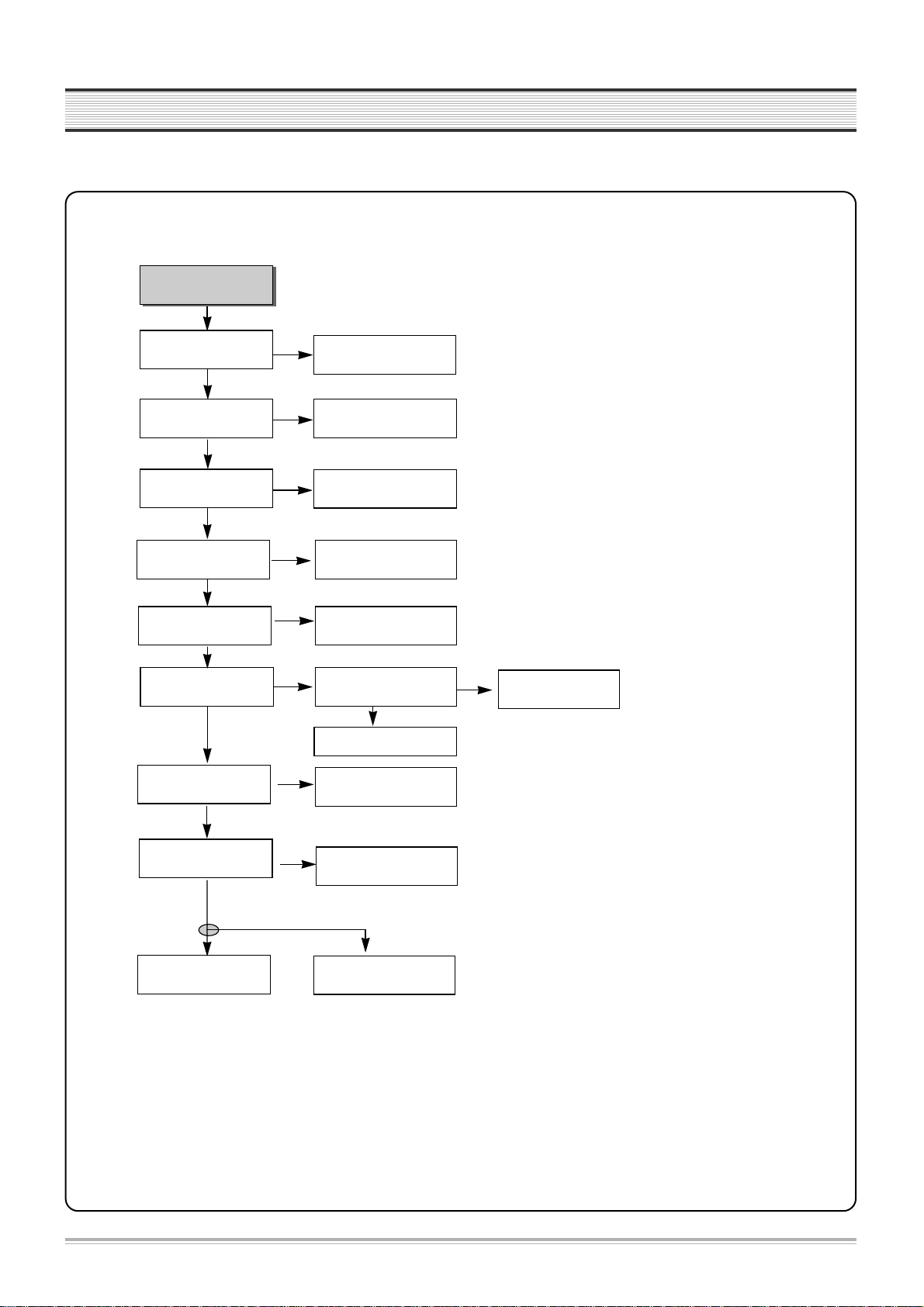
9
TROUBLESHOOTING
Cassette tape isnÕt inserted.
Is 5V voltage obtained at Loading
parts IC501 pin#63?
Is 14V voltage obtained at
Capstan Motor P501 pin#2?
Check at EVER 14V
Check L526.
Connect Capstan and Loading Motor.
Check connector and Capstan Motor.
YES
NO
NO
NO
Is 13V voltage obtained at Each
parts of Loading Motor?
Replace Loading Motor.
Check D825 and POWER circuit.
D. No CASSETTE Loading
YES
YES
E. AUTO STOP in Playback mode
VCR stops automatically in
playback mode.
Check R544,C516 and P501
pin#11.
Check S501, S502 REEL Sensor.
Is D.PG/FG pulse at IC501
pin#90 normal ?
Is C. FG pulse at IC501 pin#87
normal ?
Is there REEL Pulse at IC501
pin#79, 80?
Check and replace IC501.
NO
YES
YES
YES
NO
Check C.FG(R543,C517) and
P501 pin#1.
NO
10
TROUBLESHOOTING
F. DRUM Motor stops
G. CAPSTAN doesnÕt rotate
CAPSTAN doesnÕt rotate.
Is EVER 14V voltage obtained
at P501 pin#2?
YES
NO
NO
NO
YES
YES
Is Capstan PWM fit to
IC501 pin#77?
Is 3.2V voltage obtained
at P501 pin#5?
Is 2.7V voltage obtained
at P501 pin#9?
Check P501 Connector and
Capstan Motor.
Check EVER 14V.
(L526)
Check Capstan FG
(IC 501 pin# 87).
Check
R541,R540,R539,R538,C518
Check R537,R536,C521
DRUM Motor stops.
Is 14V voltage obtained at P501
pin#2?
YES
NO
NO
NO
YES
YES
Is DRUM PWM fit to IC 501
pin#76?
Is 2.6V voltage obtained at
P501 pin#12?
Check Capstan Motor and
DRUM Motor.
Check EVER 14V
(L526).
Check DRUM PG/FG
(IC 501 pin# 90).
Check R534,R535,C519,C520.
NO
11
TROUBLESHOOTING
3. VIDEO circuit
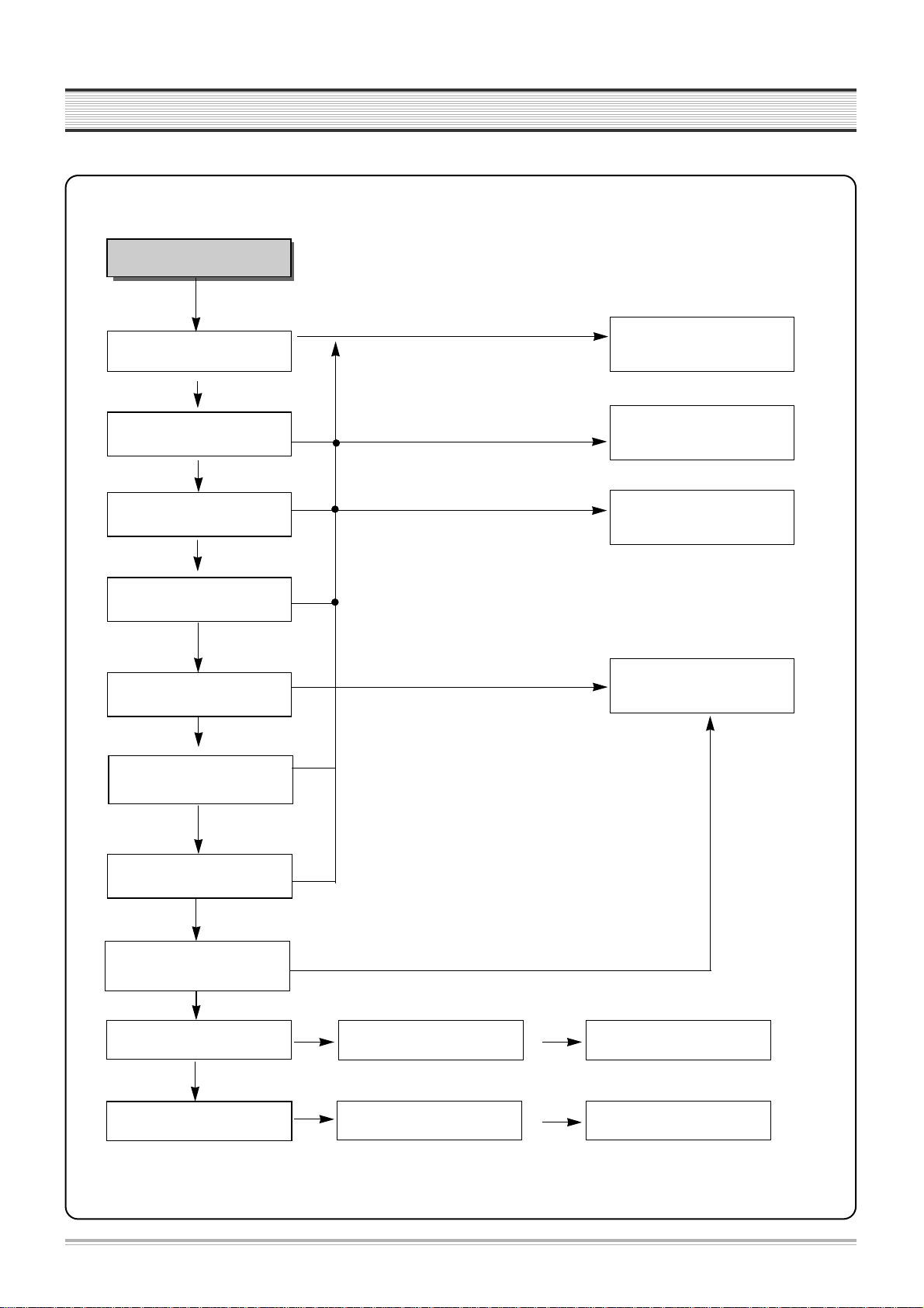
A. EE screen doesnÕt appear
EE MODE Picture NG
Is Video signal input at
IC301 pin#48,50,52,54?
Is 5V supplied at
pin#42,55,72,91of IC301?
Is C.S, DATA, CLOCK signal
input pin#67,68,69 of IC301?
Check IF and LINE IN JACK.
Check POWER circuit.
Check IC501
pin #58,71,72.
NO
YES
YES
NO
NO
YES
Is signal output from pin#65 of
IC301?
YES
NO
Check IC301
pin#62 Q-V Sync.
Is signal input into pin#50
of IC501?
YES
NO
Check PCB Pattern.
Is signal output from
pin#52 of IC501?
YES
NO
Is 5V supplied to pin#53, 98,
99 of IC501?
Is signal output at IC301
pin#61?
YES
NO
Check PCB Pattern
Q309, Q310.
Check IC 501
YES
Check POWER circuit.
NO
Is signal input at IC301
pin#56?
Check RF Output.
Check PCB Pattern & LINE
out.
YES
YES
Check IC301.
NO
12
TROUBLESHOOTING
B. Playback picture doesnÕt appear
YES
YES
Is Y SIGNAL output at IC301
pin#46?
Is VIDEO SIGNAL output at IC301
pin#65?
Check and Replace IC301.
PB video signal missing.
Is Envelope output from IC301
pin#79?
NO
NO
Same as EE MODE check.
Is 5V supplied at IC301 pin#91?
Is SW Pulse input at IC301
pin#70?
Is 5V obtained at IC301 pin#24,
42,55,72,91?
Check POWER 5V.
Check IC501 pin#18.
Clean head or Replace head.
Check POWER 5V.
NO
NO
Check PATTERN
NO
YES
YES
YES
YES
YES
YES
NO
Does X301(4.43MHz)
oscillate?
Is Y SIGNAL input at IC301
pin#43?
NO
Check PATTERN
YES
NO
Replace X301.
NO
Check and replace IC301.
13
TROUBLESHOOTING
Is +5V supplied at IC301 pin#91?
NO
NO
YES
YES
Is VIDEO SW Pulse input at IC301
pin#70?
Is REC signal output from IC301
pin#94,95,89,90?
LP MODE: 89,90 Pin
SP MODE: 94,95Pin
Check video HEAD and Connector.
Is signal input into IC301
pin# 48,50,52,54,56?
Check POWER circuit.
Check IC501 pin#18.
Record video signal poor.
Check EE MODE.
YES
Is luminance and color signal
output from IC301 pin#78?
Replace IC301.
NO
NO
YES
C. No recording
YES
Is IC301 pin#80 REC(H) HIGH?
Check IC501 pin#45.
NO
14
TROUBLESHOOTING
NO
Is Video signal input at IC501
pin#50?
Check POWER circuit.
No OSD appears.
Is 5V obtained at IC501 pin# 53,
98, 99?
Is Video signal output at IC501
pin#52?
NO
Replace IC501.
D. No OSD(On Screen Display) appears(VCR)
YES
YES
NO
Check IC 501.
Check IC 501.
NO
Check DVD loader
NO
Check DVD video buffer(QD50,QD51,
QD52)and DVD output jack
NO
Check PCB pattern
E. No DVD Video
NO
Is power_on_H signal
output at P601 pin#11
Chage the mode with DVD
No DVD signal
Is Mode DVD mode?
Is power supplied CN2?
(In DVD loader PCB)
NO
Check Power circuit
YES
YES
NO
Check IC 501 pin#32 and PCB
pattern
Is video signal output at
P101 pin #1,3,5,7,8,9?
Is video signal input IC301 pin#54?
Check IC301 and EE mode
YES
YES
YES
15
TROUBLESHOOTING
4. AUDIO (Hi-Fi MODEL)
No sound in RF E-E mode
Is Audio signal output at IC601 pin
#3, 13?
A. No sound in E-E mode
a. RF E-E
Check IC501.
Is Audio signal output at IC251
pin#16,17?
Are CLK and DATA obtained at
IC251 pin#42,43?
NO
Is 5V obtained at IC251 pin#40?
Replace IC251.
YES
YES
Is 12V obtained at IC251 pin#34?
NO
YES
Check POWER circuit.
YES
Replace IC601.
Is 5V obtained at IC051 pin#1?
Check Power circuit.
NO
Is there SIF signal at IC051 pin#2
in RF mode?
Check RF101.
NO
YES
Is there SIF signal out at IC051
pin#30, 31?
Check IC051.
NO
YES
YES
Comparing with switching table, are SWA, B CTL SIGNAL
right at IC601 pin #9,10?
NO
Check Output JACK.
YES
YES
NO
16
TROUBLESHOOTING
b. AV1 E-E
No sound in AV1 E-E mode.
NO
Check Input AV1 JACK
Is Audio signal at IC251 pin#6, 7?
Is Audio signal output at IC601 pin
#3, 13?
Check IC501.
Is Audio signal output at IC251
pin#16,17?
Are CLK and DATA obtained at
IC251 pin#42,43?
NO
Is 5V obtained at IC251 pin#40?
Replace IC251.
YES
YES
Is 12V obtained at IC251 pin#34?
NO
YES
Check POWER circuit.
YES
Replace IC601.
YES
Comparing with switching table, are SWA, B CTL SIGNAL
right at IC601 pin #9,10?
NO
Check Output JACK.
YES
YES
NO
17
TROUBLESHOOTING
c. AV2 E-E
No sound in AV2 E-E mode.
NO
Check Input AV2 JACK
Is Audio signal at IC251 pin#8, 9?
Is Audio signal output at IC601 pin
#3, 13?
Check IC501.
Is Audio signal output at IC251
pin#19, 20?
Are CLK and DATA obtained at
IC251 pin#42,43?
NO
Is 5V obtained at IC251 pin#40?
Replace IC251.
YES
YES
Is 12V obtained at IC251 pin#34?
NO
YES
Check POWER circuit.
YES
Replace IC601.
YES
Comparing with switching table, are SWA, B CTL SIGNAL
right at IC601 pin #9,10?
NO
Check Output JACK.
YES
YES
NO
18
TROUBLESHOOTING
d. AV-F(Front) E-E
No sound
AV-F(Front)E-E mode
Is Audio signal at IC251
pin#10,11?
Check output jack.
Check Power circuit
Replace IC601
Check Input AV3 jack
Replace
IC601
Check IC501
Is Audio signal output
at IC601 pin#3,13?
12V obtained
at IC601 pin
#16?
NO
Is there
"L"at IC601
pin#9,10?
NO
Is there signal
at IC601
pin#3,13?
NO
Is 5V obtained at IC251 pin#40?
YES
YES
Is 12V obtained at IC251 pin#34?
NO
YES
YES
YES
Are CLK and DATA obtained
at IC251 pin#42,43
NO
NO
YES
YES
NO
YES
19
Are there voltage at ICD01#8(5V),
#9(3.3V),#21(5V)
Are there clocks at ICD01
#5(BCLK),#6(LRCK), #10(MCLK)?
Is there reset at ICD01 #14?
Is 12V obtained at ICD02 #8?
Check Power circuit
Check DVD board
Check signal flow circuit
Check ICD02
YES
YES
YES
NO
Are there signal at ICD02 #1,7?
YES
YES
Is 12V obtained at IC251 #34?
Is 5V obtained
at IC251 #40?
YES
No sound DVD EE mode
Is audio signal
at IC251 #4,5?
YES
Is audio signal output
at IC251 #3,13?
YES
Are CLK and DATA
obtained at IC251 pin#42,43
Is there MUTE(H)
at IC251 pin#36
Check output jack
YES
NO
Replace IC251
NO
Check IC501
NO
NO
NO
NO
NO
NO
e. DVD E-E
YES
NO
NO
 Loading...