

Page 1
Page 2
HOW TO USE THIS MANUAL
This manual describes effective maintenance procedure
for the SL125 manufactured by DAELIM Motor Co., Ltd.
To ensure safety and optimal operating conditions of the
vehicle, carry out regular inspections according to the
maintenance schedule (Section 3).
Sections 1 through 3 provide information on overall
vehicle; section 4, assembly and disassembly procedures
for external components, and section 5 describes
maintenance procedure for the engine, frame and electrical
systems.
To facilitate use of this manual, each page starts with
disassembly and system diagrams, service information,
and troubleshooting guide. If you cannot find the cause of
trouble, refer to Section 20: Troubleshooting.
Contents of this manual and specifications are
subject to change without prior notice for
improvement of vehicle quality .
No part of this publication may be reproduced
without written permission of DAELIM Motor Co.,
Ltd.,
CONTENTS
SERVICE INFORMATION
LUBRICA TION
INSPECTIONS / ADJUSTMENTS
EXTERNAL P ARTS
FUEL SYSTEM
ENGINE REMOV AL
LH.CRANK CASE COVER / KICK ST ARTER /
CONTINUOUSL Y V ARIABLE TRANSMISSION
A.C.GENERA TOR / ST ARTER CLUTCH
CYLINDER HEAD / V ALVE
CYLINDER / PISTON
TRANSMISSION/CRANKSHAFT/CRANK CASE
FRONT WHEEL / FRONT FORK / STEERING
REAR WHEEL / BRAKE / SUSPENSION /
REAR SWING ARM
BRAKE SYSTEM
GENERAL
ENGINE
FRAME
ELECTRICAL SYSTEM
CHARGING SYSTEM / BATTERY
STARTER SYSTEM
LIGHTS/METER/SWITCHES
IGNITION SYSTEM
1
2
3
4
5
6
7
8
9
10
11
12
13
14
15
16
WIRING DIAGRAM
17
TROUBLESHOOTING
18
19
20
Page 3
1-1
1. SERVICE INFORMATION
GENERAL SAFETY
················
1-1
SERVICE RULES
····················
1-1
CAUTION WHEN WIRING
··········
1-5
SERIAL NUMBER LOCATION
······
1-9
SPECIFICATIONS
··················
1-10
TORQUE VALUES
··················
1-12
SYMBOLS / ABBREVIATIONS
······
1-14
WIRING DIAGRAM
················
1-15
GENERAL SAFETY
WARNING
1. Do not run the engine for a long time in closed or not well-ventilated area because the exhaust gas contains toxic
substances such as carbon monoxide, hydrocarbon, nitric oxide.
2. The battery fluid(lean sulfuric acid) is extremely toxic. It is dangerous if skin is exposed to it or if it enters into the eye.
Be careful in handling. When exposed to the battery fluid, wash it with water and get a medical check up.(store the
battery fluid in a safe place to avoid touching by the children)
3. Pay attention not to be burned and always put on the protection gears because the engine or the muffler is hot right after
engine stops.
4. Gasoline is extremely flammable. Maintenance must performed in the place free of the open fire or electric spark.
5. When more than two person are working, always pay attention to other worker’s action and alway have safety in mind.
6. The skin exposed to used engine oil can be a major reason of the skin cancer. Pay attention not to exposed and wash
carefully with soap and water after handling.
7. If compressed air is used to clean the brake, dust scattered in the air can be breathed in by workers. Please take action not
to scatter dust in the brake cleaner, etc.
8. Flammable nitrogen gas is generated during charging the battery so charging must be performed in well-ventilated area
and free of the open fire and spark.
SERVICE RULES
1. Parts and lubrication oil must be DAELIM genuine or
recommended parts.
2. Before maintenance, remove deposit or dust from the
chasis.
1
Page 4
1-2
SERVICE INFORMATION
9. Check to see if the rubber part is worn out when
removing it and replace it if necessary . Some rubber part
is weak to gasoline and kerosene, so pay attention not to
soak with gasoline or oils.
10. Recommended grease must be applied to or filled in
the specified place.
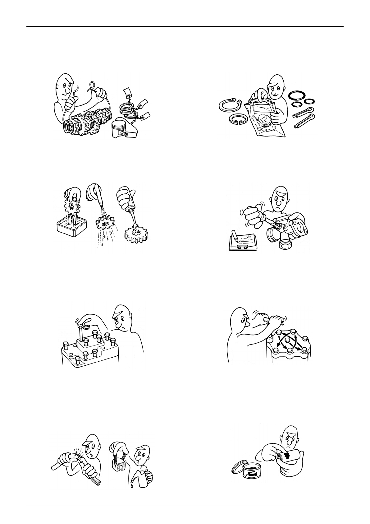
7. Align the bolts to uniform the tightening points before
tightening them when you don’t know the bolt length.
8. Bolts, nuts and pieces must be tightened from the bigger
diameter to the smaller one, from inside to outside and
diagonally with the specified torque.
5. Clean the parts after the overhaul and before the test and
remove the cleaning oil with compressed air. Apply oil
to seal face during installation.
6. Check necessary place and measure necessary data
during installation. When installing, return to the state
before removing.
3. Store the parts of each system discriminatively to install
each part in the right place.
4. After removing gasket, O-ring, piston pin clip and cotter
pin, always replace them with the new one. When
removing the snap ring, it can be easily missed after
transformation or installation.
Page 5
1-3
SERVICE INFORMATION
11. Maintenance needed to use the specialized tools must
performed with the right tool.
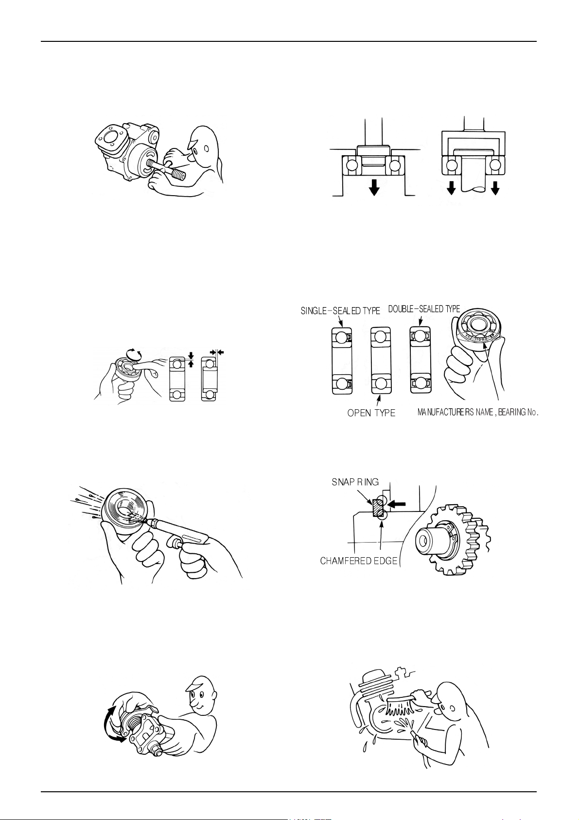
12. Never reuse the ball bearing removed with the ball
applied pressure when removing press-fitted the
bearing.
13. Check the smooth rotation of inner or outer race of the
ball bearing by rotating it manually .
• Replace the ball bearing having excessive axial/
longitudinal hanging.
•Wipe the ball bearing likely to have hanging with
cleaning oil.(except double-sided sealed type ball
bearing)
• Replace the ball bearing of which press-fitted part is
slacked at the case or shaft.
14. Pay attention to installation direction in case of the
single-sided sealed ball bearing. Install the opendirection or double-sided sealed bearing in the way
that the face marked with manufacturer and size
should direct to the outer axle.
15. When blowing the ball bearing with compressed air
after cleaning, keep the race from rotating. High speed
rotation of the race may damage the bearing. Prior to
installation, apply oil or grease to the bearing.
16. Install the snap ring so that chamfered side directs to
the load-applied side. After installation, check the
proper installation by rotating the snap ring.
17. Check each part for proper tightening and operation
after installation.
18. The brake fluid and coolant can damage the painted
plastic or rubber parts. Keep these parts from
contacting with them and wash these parts with water
in case of contact.
’
Page 6
1-4
SERVICE INFORMATION
21. Keep the pneumatic system interior or the engine
interior from the infiltration of dust.
22. Install the gasket mounted in the contact surface of
each case of the engine while removing gasket
material completely. Remove damaged contact surface
by wiping with the oil stone equally .
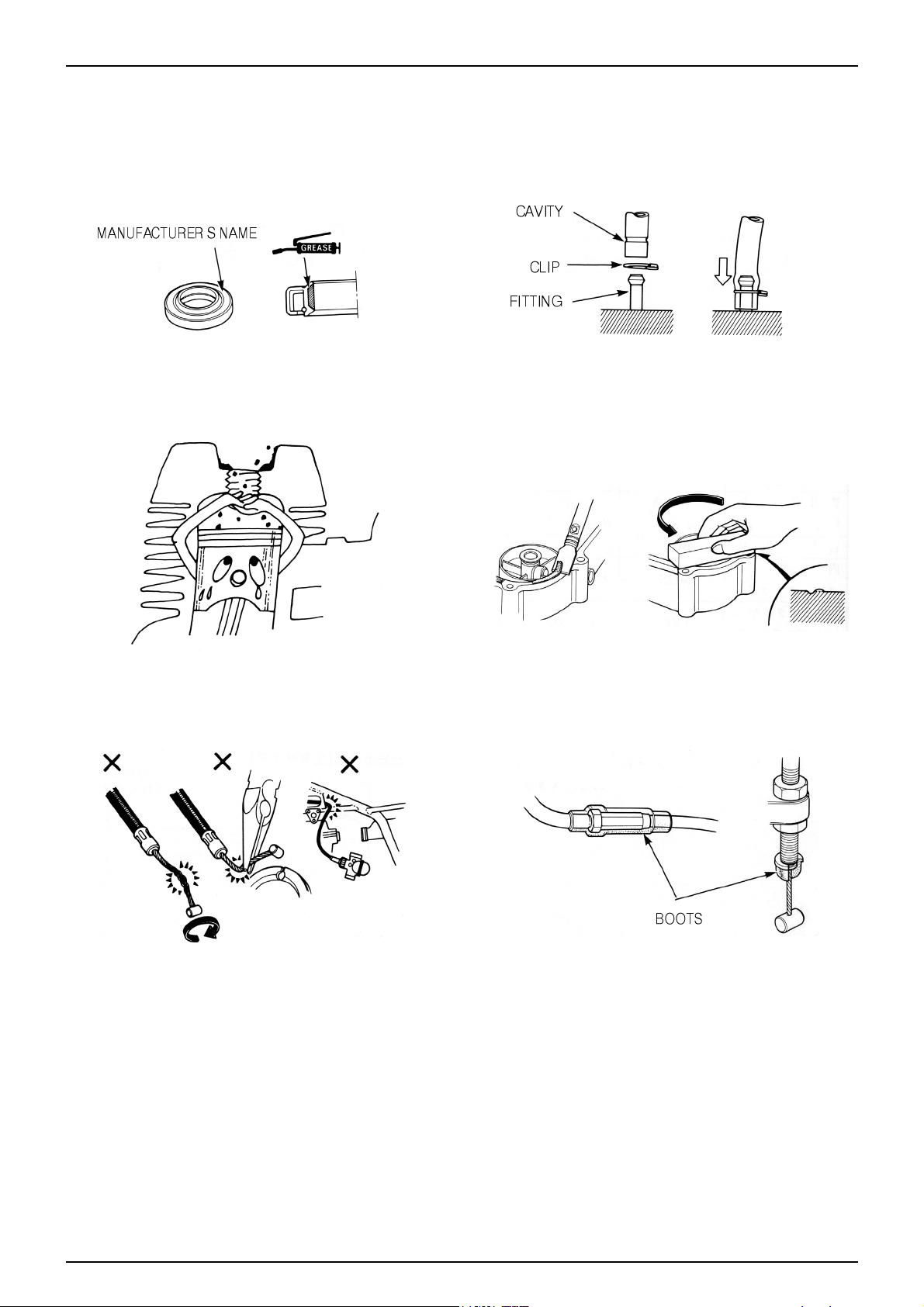
19. Install the oil seal so that the manufacturer marked
surface directs outer surface.(direction not covered
with oil)
• Pay attention not to bend or damage the lip
• Apply the grease to the lip
20. Connect the tube until the tube fully inserted in the
joint. Install the clip if it is supplied. Replace the tube
having slacked end.
23. Pay attention not to bend the cable excessively.
Transformed or damaged cable may cause malfunction
or damage.
24. Install the boots with the installing groove by inserting
the boots into the groove.
’
Page 7
1-5
SERVICE INFORMATION
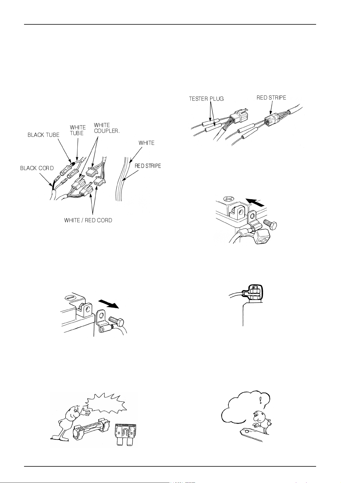
•Each cord must be connected depending on its color.
When connecting different cord, attach color tube
around the connector. Connect the coupler to the
connector with same color and same pin number .
•Identify the two-colored cord by main color first and
then spriped color .
•When measuring voltage or resistance of the cord
terminal using tester, contact the tester plug behind of
the coupler. Pay attention not to open the cord terminal
and contact the tester plug from the front of the coupler
in case of water-proof coupler.
•Recheck the condition of contact, securing and
continuity of each part after maintenance.
•When connecting the battery, the plus terminal must be
connected first.
•After connecting the terminal, apply the grease to the
terminal.
•When disconnecting the battery, the minus terminal
must be disconnected first.
•Make sure that the tool such as spanner do not contact
with the frame.
•Connect covers to the terminal after maintenance.
•If the fuse is short-circuited, find out the cause and
repair. Replace with the fuse having the specified
capacity .
•If there is rust in the terminal, remove the rust with sand
paper prior to connecting.
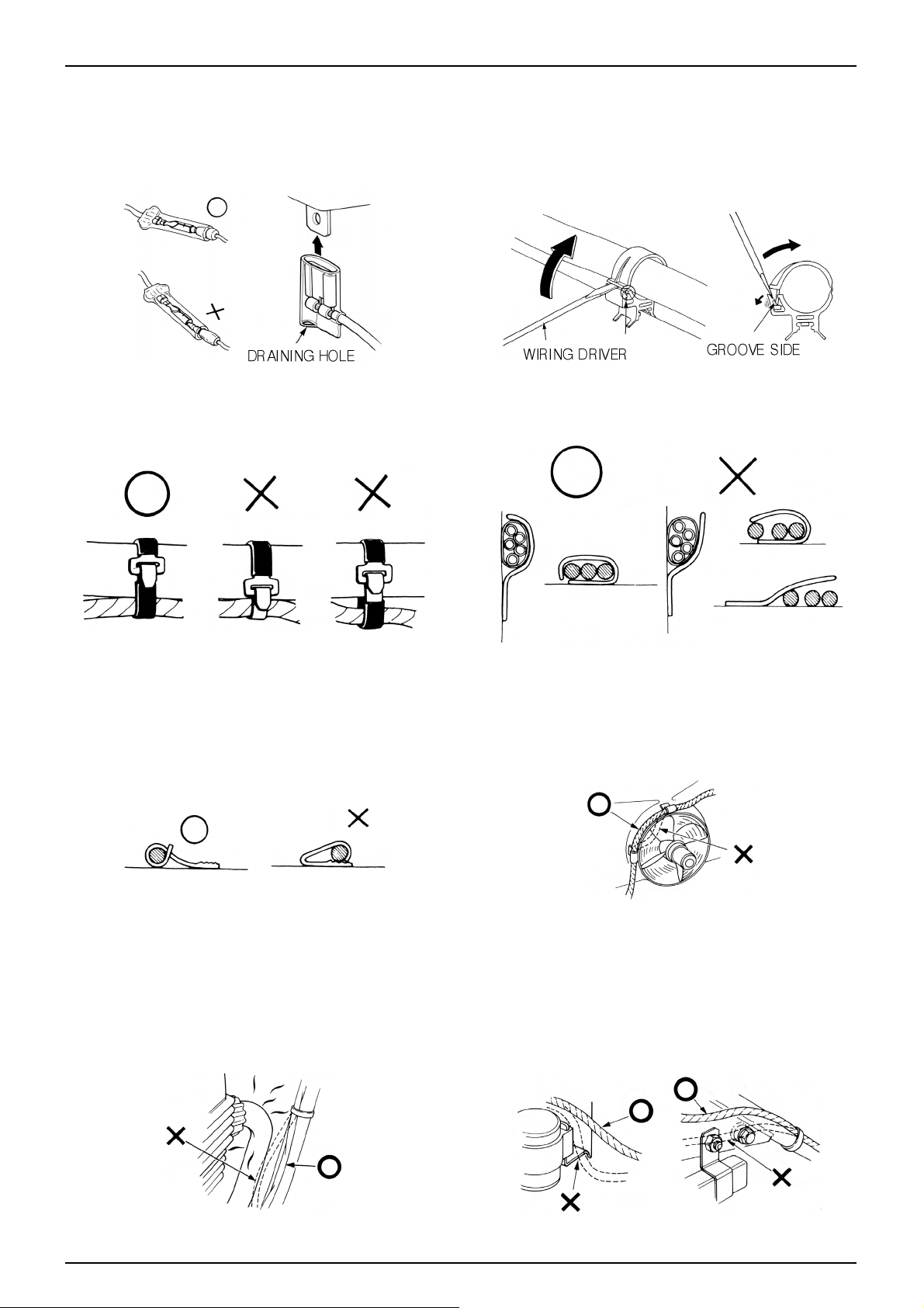
CAUTION WHEN WIRING
VALIDATION
OF CAPACITY!
REMOVE
THE
RUST!
Page 8
1-6
SERVICE INFORMATION
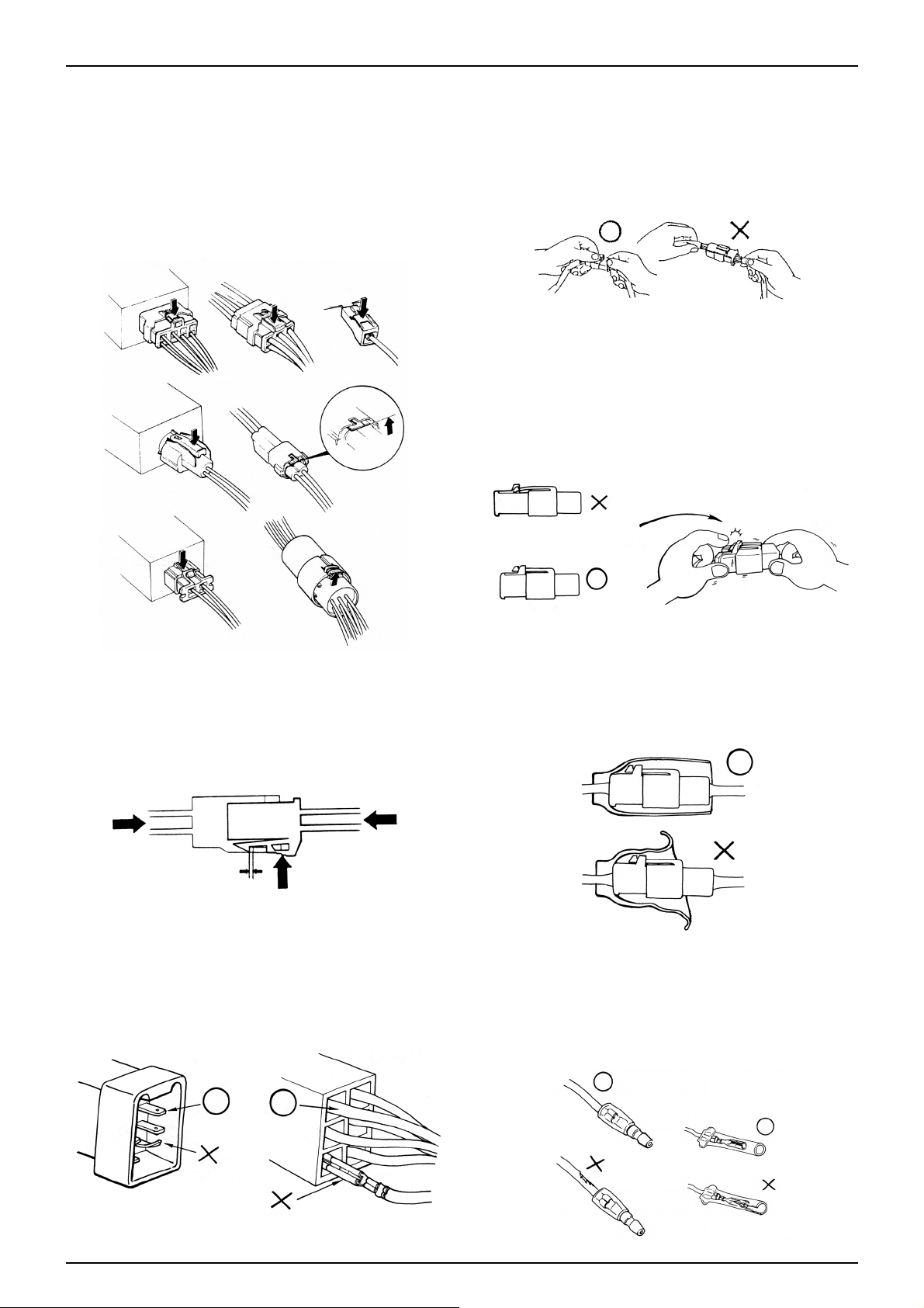
•Insert the lock of the coupler until the lock is fully
secured.
•Turn off the main switch before connecting/disconnecting.
•Release the lock to disconnect the lock of the coupler.
•The lock of the coupler has two types according to
releasing method(press type and pull type) so release it
properly according to the shape.
- Typical releasing method of the coupler is illustrated in
the following.
•When disconnecting the coupler, disconnect it while
holding the coupler body. Pull while holding the wire
harness cord and do not remove the coupler connection.
•Release the lock by inserting the coupler slightly and
then narrowing connection to remove the coupler .
•Pay attention not to damage the vinyl cover of the
coupler.
•Check to see if there is bended terminal and secure it to
avoid disconnecting.
•If the wire harness coating is damaged, repair by
winding vinyl tape or replace it.
•Prior to connecting the connector, make sure that the
cover is not damaged and the mess terminal is not
opened.
Page 9
1-7
SERVICE INFORMATION
•Wire band must be secured firmly in the specified
location of the frame. In case of aluminium band,
secure the wire harness to the coated part.
•Secure the wire harness firmly using the clamp.
•Insert the connector until the vinyl cover is fully
inserted into the terminal.
•The opening of the vinyl cover must face at the ground
direction but in case of the plain connector, the draining
opening must face at the sky direction.
•When removing T-start, broaden the groove of T-start
using the wiring driver and release the torque.
•Connect the harness and the hose to T-start and then
insert until the groove is locked.
•When removing T-start from the frame, replace it with
the new one.
•In case of the weld clamp, do not clamp in the welded
part.
•When clamping the wire harness, make sure that the
harness is not contacted with the shaft or rotating part.
•When clamping the wire, pay attention not to contact
with hot part.
•The wire harness must be routed without contacting
with the end of the lamp or any sharp edge.
•The wire harness must be routed without contacting
with the end of the bolt or the piece.
Page 10
1-8
SERVICE INFORMATION
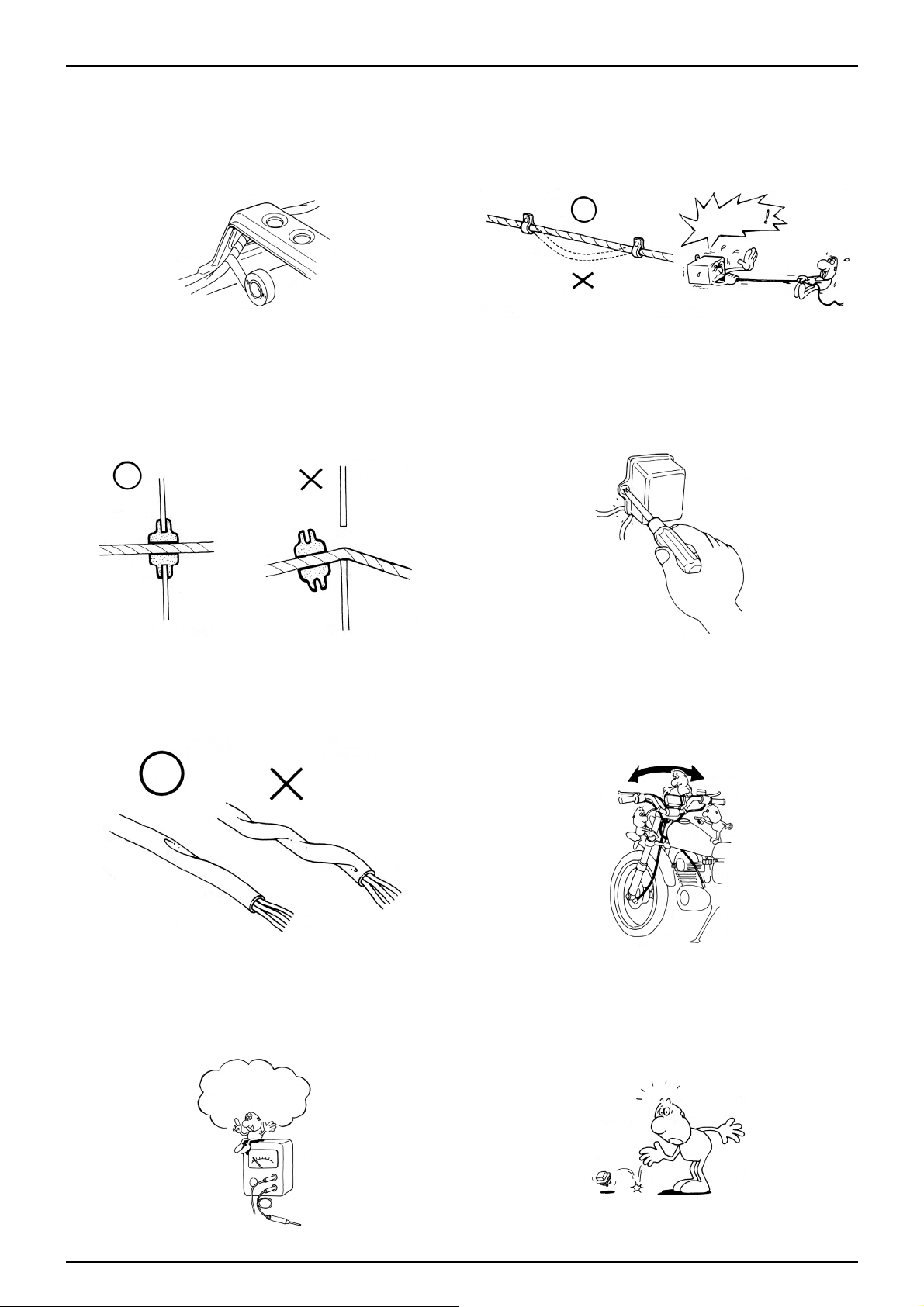
•If necessary, lock the wire harness properly . •When mounting parts, make sure that the wire harness
is not pressed by the parts.
•In case that the wire harness is contacted with the end or
the sharp edge, protect both parts with tube or tape.
•The wire must not hang down or be pulled excessively.
•Do not twist the wire harness. •Wire the wire harness not to be pulled or expanded
when the handle is turned to the right or the left
completely. Avoid excessive bending or chewing and
interference with the engine.
•Prior to using the tester, please read the manual care-
fully and understand the contents.
•When testing the resistance of the tester, the zero
adjustment must be performed before testing.
•Do not drop or throw the parts especially
semiconductor contained parts because these parts may
be damaged by the impact of the drop.
NOT TO
PULL!
Is this
measurement range or
configuration in accord
with the manual?
Page 11
1-9
SERVICE INFORMATION
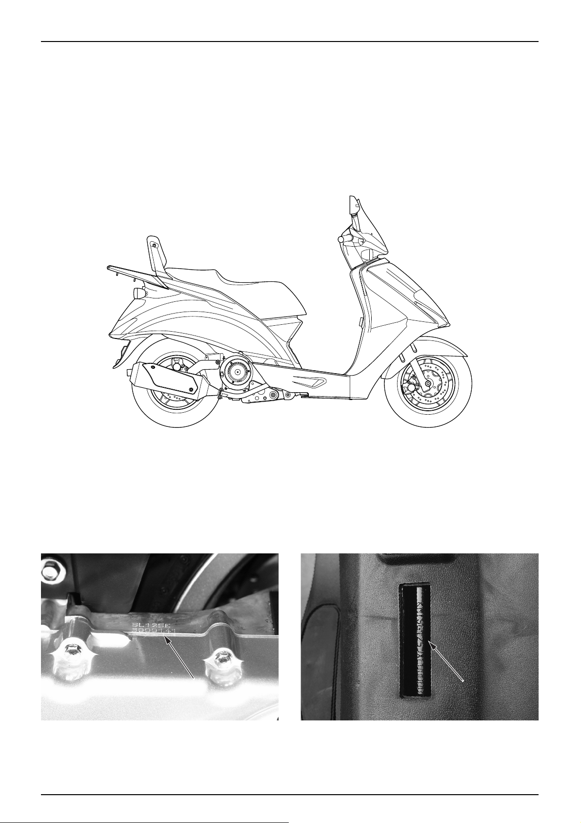
SERIAL NUMBER LOCATION
ENGINE SERIAL NUMBER LOCA TION FRAME SERIAL NUMBER LOCA TION
Page 12

1-10
SERVICE INFORMATION
ITEM SPECIFICATIONS
1,965 mm
690 mm
1,230 mm
1,350 mm
780 mm
120 mm
125 kg
255 kg
Underbone
Telescopic / 77mm
Swing arm / 66mm
120 / 70 - 12 53k / Tubeless
130 / 70 - 12 62k / Tubeless
2.00 Kgf / ㎠ (200 kPa)
2.00 Kgf / ㎠ (200 kPa)
2.00 Kgf / ㎠ (200 kPa)
2.25 Kgf / ㎠ (225 kPa)
Hydraulic disk
Drum brake
8.0ℓ
1.7ℓ
25。
86 mm
90 ㎠
Oil cooled / air cooled 4 cycle SOHC engine
1(Single cylinder), front angle 80。
56
×50.7 mm
124.9 ㏄
10.8 : 1
SOHC chain drive
1.1ℓAfter disassembly
0.75ℓAfter Oil change
0.8ℓAfter Oil filter change
0.9ℓAfter Oil change with Oil in the Oil hose removed
Forced pressure splash type
Wet sump
14.0 kgf / ㎠ (550 rpm)
5。BTDC
14。ABDC
18。BBDC
1。BTDC
0.12±0.12 mm
0.12±0.12 mm
OVERALL LENGTH
OVERALL WIDTH
OVERALL HEIGHT
WHEEL BASE
SEAT HEIGHT
GROUND CLEARANCE
DRY WEIGHT
GROSS WEIGHT
TYPE
FRONT SUSPENSION / STROKE
REAR SUSPENSION / STROKE
FRONT TIRE SIZE / TYPE
REAR TIRE SIZE / TYPE
TIRE PRESSURE 1 PERSON FRONT
REAR
2 PERSON FRONT
REAR
FRONT / REAR BRAKE
PARKING BRAKE
FUEL TANK CAPACITY FULL CAPACITY
RESERVE CAPACITY
CASTER ANGLE
TRAIL
FRONT FORK OIL CAPACITY
TYPE
CYLINDERS / ARRANGEMENT
BORE AND STROKE
DISPLACEMENT
COMPRESSION RATIO
VALVE TRAIN
OIL CAPACITY
LUBRICATION SYSTEM
AIR CLEANER TYPE
CYLINDER COMPRESSION
INTAKE VALVE OPEN
CLOSED
EXHAUST VALVE CLOSED
CLOSED
VALVE CLEARANCE (COOLING-OFF PERIOD)
INTAKE
EXHAUST
DIMENSIONS
FRAME
ENGINE
SPECIFICA TIONS
Page 13

1-11
SERVICE INFORMATION
ITEM SPECIFICATIONS
CV type ( vacuum ) 24.2 mm
BDS 26 - 112
Auto-bystarter
# 95
1 and ½ trust out
13 mm
1.800±100 ( rpm )
Automatic Transmission
3.231 (42/13)
2.786 (39/14)
C.D.I Ignition
15。BTDC / 1.800 ( rpm )
12V 10A / 5,000 ( rpm )
Closed type (MF) 12V 8AH
CR8EH - 9 (NGK)
0.8 - 0.9 mm
15A
Kick / starter motor
12V 60 / 55W
12V 5W
12V 10W
×4
12V 21 / 5W
14V 3W
14V 3W
×2
12V 1.7W
×2
14V 1.4W
12V 5W
14V 3W
TYPE / VENTURI BORE
MODEL MARK
CHOKE TYPE
MAIN JET
PILOT SCREW INITIAL SETTING
FLOAT LEVEL
IDLE SPEED
CLUTCH TYPE
PRIMARY REDUCTION
SECONDARY REDUCTION
IGNITION SYSTEM
IGNITION TIMING F MARK
AC GENERATOR CAPACITY
BATTERY TYPE / CAPACITY
SPARK PLUG
SPARK PLUG GAP
FUSE CAPACITY
STARTING SYSTEM
HEADLIGHT ( HIGH / LOW )
POSITION LIGHT
WINKER LIGHTS ( FR / RR )
TAIL / STOP LIGHT
HIGH-BEAM PILOT
WINKER PILOT
METER LIGHTS
TRUNK LAMP
LICENSE LAMP
PARKING BRAKE PILOT
CARBURETOR
DRIVE TRAIN
ELECTRICAL
SYSTEM
Page 14
1-12
SERVICE INFORMATION
ITEM REFERENCETORQUE VALUE
THREAD DIA
(mm)
Q’TY
1.1 kgf·m
2.5 kgf·m
0.8 kgf·m
1.0 kgf·m
5.5 kgf·m
7.5 kgf·m
5.5 kgf·m
1.0 kgf·m
1.2 kgf·m
5.5 kgf·m
2.0 kgf·m
1.0 kgf·m
0.4 kgf·m
0.9 kgf·m
1.2 kgf·m
1.0 kgf·m
0.9 kgf·m
1.0 kgf·m
9.5 kgf·m
0.9 kgf·m
3.2 kgf·m
1.0 kgf·m
1.0 kgf·m
Apply engine oil
20
12
5
6
12
12
12
8
12
30
8
6
6
6
6
8
8
6
22
6
12
6
6
1
1
4
2
1
1
1
1
1
1
4
2
1
4
8
1
1
3
1
2
4
3
1
OIL FILTER CAP
OIL DRAIN PLUG BOLT
VALVE ADJUST SCREW LOCK NUT
CYLINDER HEAD BOLT
FLYWHEEL BOLT
DRIVE FACE NUT
CLUTCH OUTER BOLT
CAM CHAIN TENSIONER PIVOT BOLT
SPARK PLUG
DRIVE PLATE
CAM SHAFT HOLDER NUT
CAM CHAIN TENSIONER FLANGE BOLT
CAM CHAIN TENSIONER PAN SCREW
CYLINDER HEAD COVER BOLT
MISSION COVER BOLT
MISSION COVER DRAIN BOLT
MISSION COVER CHECK BOLT
COOLING FAN BOLT
STARTING CLUTCH NUT
STARTER MOTOR FLANGE BOLT
RADIATOR OIL BOLT
OIL PUMP FLAT SCREW
OIL PUMP DRIVEN GEAR NUT
TORQUE V ALUES
ENGINE
ITEM REFERENCETORQUE VALUE
THREAD DIA
(mm)
Q’TY
7.0 kgf·m
0.20 kgf·m
6.0 kgf·m
7.5 kgf·m
2.0 kgf·m
5.0~7.0 kgf·m
4.0~4.5 kgf·m
4.0~4.5 kgf·m
6.0~8.0 kgf·m
4.5 kgf·m
4.0 kgf·m
1.5 kgf·m
Initial torque
Apply locking agent
26
26
10
10
8
12
8
8
14
10
10
10
1
1
1
4
2
1
3
3
1
2
2
1
STEERING STEM NUT
STEERING TOP THREAD NUT
HANDLE POST NUT
FRONT FORK BOTTOM BRIDGE BOLT
FRONT FORK SOCKET BOLT
FRONT AXLE NUT
FRONT BRAKE DISK BOLT
REAR BRAKE DISK BOLT
REAR AXLE NUT
ENGINE HANGER NUT
MAIN STAND BOLT
SIDE STAND PIVOT BOLT
FRAME
Page 15
1-13
SERVICE INFORMATION
ITEM REFERENCETORQUE VALUE
THREAD DIA
(mm)
Q’TY
4.5 kgf·m
2.7 kgf·m
0.6 kgf·m
2.3 kgf·m
1.8 kgf·m
1.8 kgf·m
0.15 kgf·m
3.0 kgf·m
1.0 kgf·m
1.0 kgf·m
10 kgf·m
0.4 kgf·m
4.0 kgf·m
4.0 kgf·m
4.0 kgf·m
Apply locking agent
Apply locking agent
10
8
8
8
8
8
4
10
6
6
6
5
10
10
10
1
2/2
1/1
1/1
1/1
2/2
2/2
2/2
1/1
1/1
1
1
1
1
1
SIDE STAND PIVOT NUT
FRONT / REAR BRAKE CALIPER BRACKET BOLT
FRONT / REAR BRAKE CALIPER BLEEDER VALVE
FRONT / REAR BRAKE CALIPER SLIDE PIN
FRONT / REAR BRAKE CALIPER BRACKET PIN BOLT
FRONT / REAR BRAKE HANGER PIN
FRONT / REAR MASTER CYLINDER RESERVOIR CAP SCREW
FRONT / REAR BRAKE HOSE OIL BOLT
FRONT / REAR MASTER CYLINDER LEVER PIVOT BOLT
FRONT / REAR MASTER CYLINDER LEVER PIVOT LOCK NUT
REAR BRAKE ARM FLANGE BOLT
SPEEDOMETER GEAR BOX OVAL SCREW
REAR CUSHION UPPER BOLT
REAR CUSHION LOWER BOLT
REAR CUSHION DAMPER ROD LOCK NUT
ITEM ITEMTORQUE VALUE
TORQUE VALUE
0.5 kgf·m
1.0 kgf·m
2.2 kgf·m
3.5 kgf·m
5.5 kgf·m
0.4 kgf·m
0.9 kgf·m
1.2 kgf·m
2.7 kgf·m
4.0 kgf·m
5mm BOLT, NUT
6mm BOLT, NUT
8mm BOLT, NUT
10mm BOLT, NUT
12mm BOLT, NUT
5mm SCREW
6mm SCREW
6mm FLANGE BOLT, NUT
8mm FLANGE BOLT, NUT
10mm FLANGE BOLT, NUT
Torque values listed above are for specific tightening points. T orque values for other items are listed in the following table.
SH (Small Head) : Indicates 6mm bolt of 8mm flange head.
Page 16
SYMBOL
CAUTION
NOTE
SYMBOL
1-14
SERVICE INFORMATION
SYMBOLS / ABBREVIATIONS
The following symbols are used in this manual to represent job-related warnings or cautions.
MEANING
Indicates dangerous area. Serious
accident may result if instructions are not
followed.
The following symbols indicate oil adding, oil change, or parts.
MEANING
Add oil. If there is no specific oil indicated, use the designated or recommended engine oil.
Apply grease
Indicates reference page. (example : Refer to page 3-1)
MEANING
Indicates important work. Minor injury or
vehicle part damage may result if instruction
are not followed.
Indicates general safety matters. Provides
safety and appropriate handling procedures.
(⇨3-1)
ASS’Y
The following abbreviations are used in this manual.
ASSEMBLY
Left
Right
LH.
RH.
SYMBOL
WARNING
OIL
GREASE
Page 17
1-15
SERVICE INFORMATION
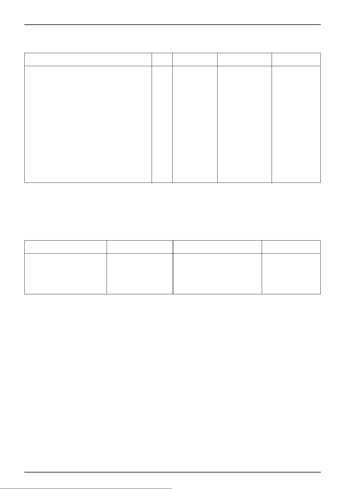
WIRING DIAGRAM
FR.BRAKEHOSE
FRAMEEARTHCONNECTOR
(TIGHTATTHESAMETIMEWITHTHEREG.REC.)
THROTTLECABLE
STARTERS/WUNIT
FR.STOPS/WCONNECTOR
FR.BRAKEHOSE
SEATOPENCABLE
REG.RECTIFIER
MAINS/W
SPEEDOMETERCABLE
CABLEGUIDE
RR.BRAKEHOSE
RR.STOPS/WCONNECTOR
HAZARDS/WUNIT
HORNS/WUNIT
RR.BRAKEHOSE
LH.FR.WINKERLIGHT
CONNECTINGCONNECTOR
CABLEGUIDE
RESISTOR
30W5.9
LIGHTINGS/WUNIT
HEADPIPE
SPEEDOMETER
CABLEGUIDE
SOCKETCOMP.
A.P.WINKERRELAY
DIMMERS/WUNIT
WINKERS/WUNIT
FRONTFENDER
CABLEGUIDE
THROTTLECABLE
PRESSTOATTACHTHE
SEL.SECTIONTOTHEPIPE
FR.BRAKEHOSE
HORNCOMP.
SPEEDOMETERCABLE
Y
SEATLOCKCABLE
THROTTLECABLE
BREATHERTUBE
DRAINTUBE(CARB.)
AIRCLEANERINLETDUCT
FUELUNIT
FUELTUBE
FUELTANK
FUELPUMP
TUBECLAMP
CABLECLIP
CABLESETT.PIPE
LH.RR.WINKERCORD
LH.RR.WINKERLIGHT
FUELUNITCORD
LH.RADIATORHOSE
BATTERY
DETAILOF"Z"
THROTTLECABLE
FULETUBE(INSU)
FULETUBE(CARB)
CORDCLIP
PLUNGERASS'Y.
DRAINTUBE
BREATHERTUBE
FUSE
BREATHERTUBE
STARTERMAGNETICBATTERY+CABLE
BATTERYEARTHCABLE
RR.BRAKEHOSEB
RH.RADIATORHOSE
RR.BRAKEHOSEB
WIREHARNESS
WIRECLIP
HOSECLAMP
WIREHARNESS
HOSECLAMP
RH.RR.WINKERCORD
RH.RR.WINKERLIGHT
WIRECLIP
WIRECLIP
WIRECLIP
TAILLIGHTCORD
LICENSELIGHTCORD
I/G.COIL
RR.BRAKEHOSEB
STARTERMOTORCABLE
HIGHTENTIONCORD
STARTERMAGNETICS/W
PLUNGERASS'Y
Page 18
1-16
SERVICE INFORMATION
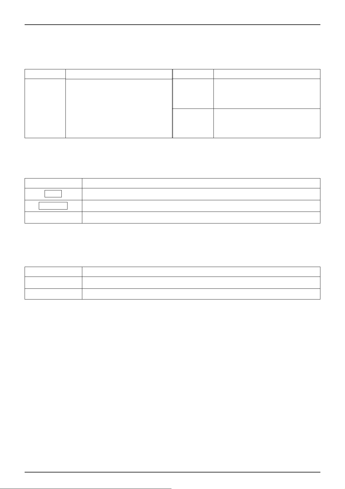
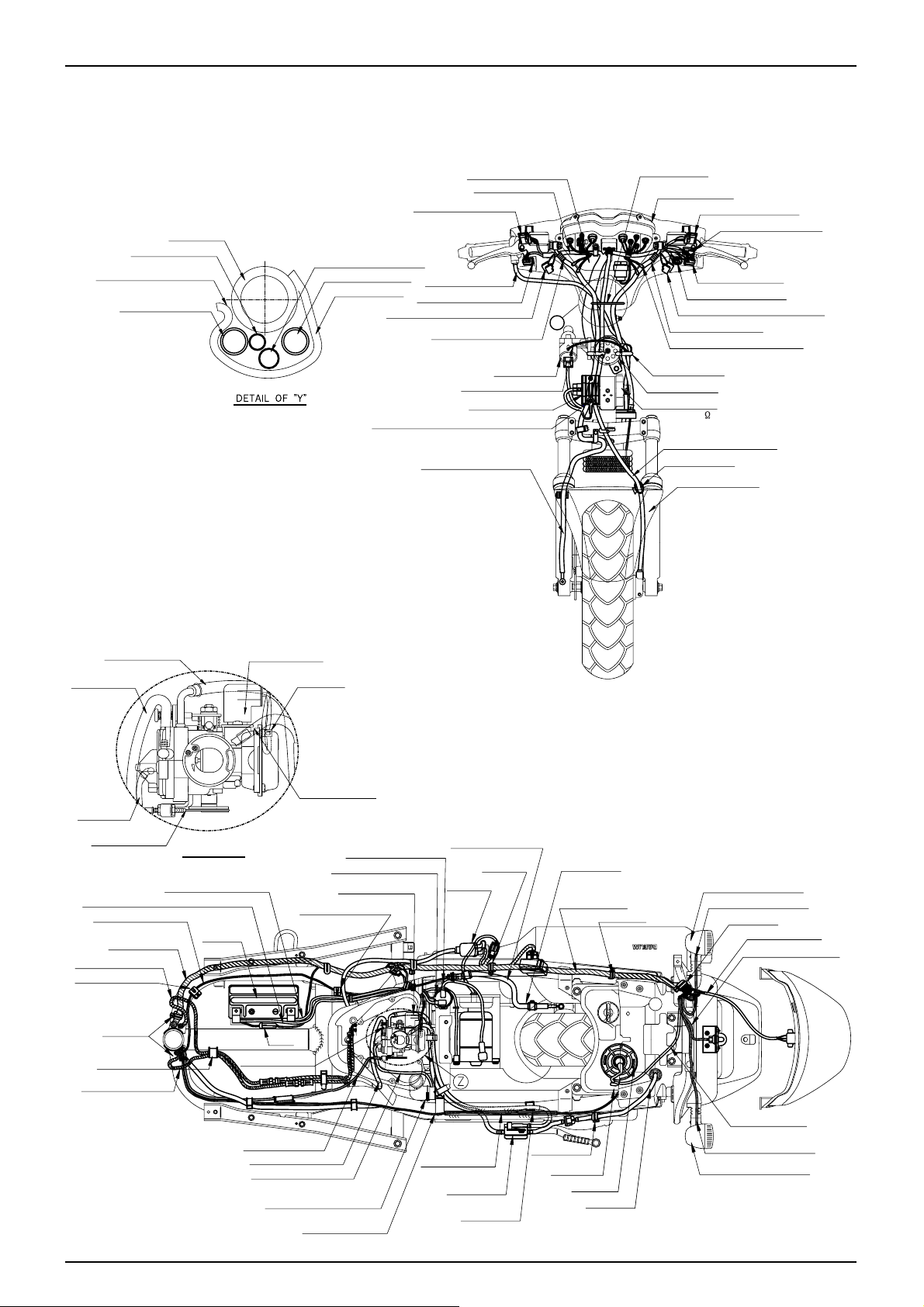
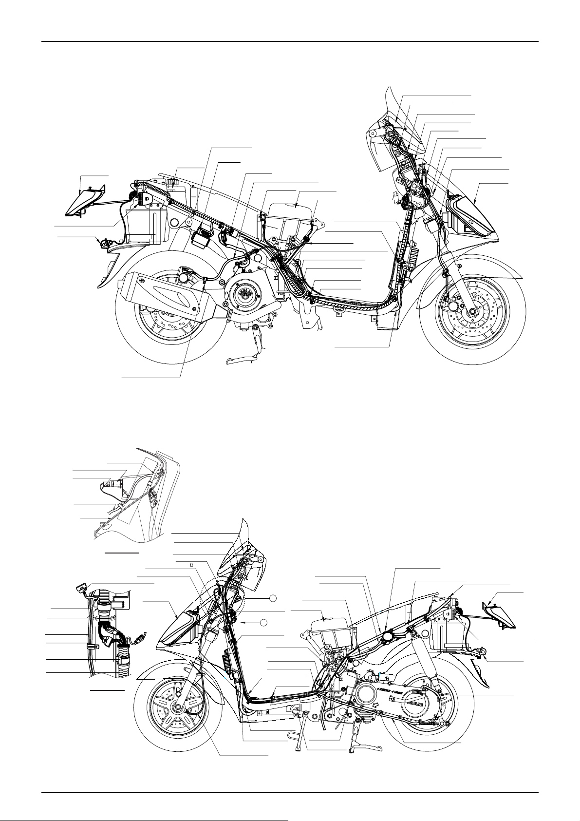
MASTERCYLINDERASS'Y
FR.BRAKEHOSE
SPEEDOMETERCABLE
THROTTLECABLE
MAINS/W
SEATLOCKCABLE
WIREHARNESS
AIRCLEANER
TRUNKLAMP
TRUNKLAMPS/W
PARKINGBRAKECABLE
RR.BRAKEHOSEB
BLEEDERTUBE
BATTERYEARTHCABLE
HIGHTENSIONCORD
THROTTLECABLE
WIREHARNESS
RH.RADIATORHOSE
STARTERMAGNETICBATTERY+CABLE
STARTERMOTORCABLE
I/G.COIL
CDIUNIT
FUELTANK
TAILLIGHT
RH.RR.WINKERLIGHT
LICENSELIGHT
RR.BRAKEHOSEB
WIREHARNESS
REGULATERECTIFIER
SPEEDOMETERCABLE
HEADLIGHT
MASTERCYLINDERASS'Y
RR.BRAKEHOSEA
SOCKETCOMP.
CHARGESOCKETASS'Y
WIREHARNESS
HEADLIGHTCORD
INNERBOX
DETAILOF"A"
HEADLIGHT
HEADLIGHTCONNECTING
COUPLER(4P.FEMAIL)
THROTTLECABLE
AIRCLEANER
FUELTUBE(CARB')
FUELTUBE(INSU.)
FUELPUMPASS'Y
FUELSTRAINERCOMP.
FUELTUBE(TANK)
TAILLIGHT
LH.RR.WINKERLIGHT
LICENSELIGHT
BREATHERTUBE
PARKINGBRAKECABLE
CABLESETTINGPIPE
RR.BRAKEHOSEB
X
A
DRAINTUBE
SIDESTANDS/W
SEATLOCKCABLE
THROTTLECABLE
CABLECLAMP
BREATHERCABLE
RR.BRAKEHOSEB
RH.RADIATORHOSE
LH.RADIATORHOSE
SPEEDOMETERCABLE
SPEEDOMETERCABLE
SPEEDOMETERCABLE
SOCKETCOMP.
WIRECLAMP
(SOCKETCOMP.)
SEATLOCKCABLE
THROTTLECABLE
WIREHARNESS
WIRECLAMP
HORNCOMP.
RESISTOR30W5.9
VIEW"X"
Page 19
2-1
2. LUBRICATION
SERVICE INFORMATION
GENERAL SAFETY
WARNING
1.The exhaust gas contains poisonous substance. Do not keep engine idling in a closed or poorly ventilated place for a
long period of time.
2.Used engine oil may cause skin cancer if repeatedly left in contect with the skin for prolonged periods. It is desirable
not to handle used oil frequently; however, wash your hands thoroughly with soap and water immediately after
handling the used oil.
3.The oil pump can be serviced without removing the engine from the frame.
ENGINE OIL
TRANSMISSION OIL
TORQUE VALUES
OIL FILTER SCREEN CAP
1.5㎏f·m
OIL FILTER COVER BOL T
1.1㎏f·m
OIL PUMP MOUNTING BOLT
1.1㎏f·m
OIL DRAIN PLUG BOLT
2.5㎏f·m
2
SERVICE INFORMATION
······
2-1
TROUBLESHOOTING
··········
2-2
ENGINE OIL LEVEL INSPECTION··2-3
ENGINE OIL CHANGE
········
2-3
OIL FILTER ELEMENT CHANGE··2-4
OIL PUMP
··················
2-4
RADIATOR
··················
2-7
TRANSMISSION OIL INSPECTION··2-8
LUBRICATION POINTS
······
2-9
OIL CAP ACITY
RECOMMENDED
OIL
1.1ℓ (After disassembly)
0.9ℓ (After Oil change with Oil in the Oil hose removed)
0.8ℓ (After Oil filter change)
0.75ℓ (After Oil change)
API service classification : SE, SF, SH grade
Viscosity : SAE10W-30
(Use appropriate type of oil with viscosity satisfying
the atmospheric temperature
In your riding area based on the table shown on the
right side.)
OIL CAP ACITY
RECOMMENDED OIL
0.15ℓ (Full capacity)
0.14ℓ (After oil change)
DMC Pure mission oil or SAE 80W/90
-10 0 10 20 30 40℃
Page 20

2-2
LUBRICA TION
TROUBLESHOOTING
Oil level low
•Oil consumption.
•External oil leaks.
•Worn piston ring or incorrect piston ring installation.
•Worn valve guide or seal.
Oil contamination
•Oil or filter not changed often enough.
•Faulty head gasket.
•Worn piston rings.
Low or no oil pressure
•Clogged oil orifice.
•Incorrect oil being used.
Page 21
ENGINE OIL LEVEL INSPECTION
● Erect the motorcycle on the main stand.
● Warm up the engine to heat the engine oil to an
appropriate level.
● Stop the engine, and check the oil level line on the
sight-glass installed on the LH. crank case cover .
● If the oil level is between the lower and higher sightglass oil level line, oil level is satisfactory. If the oil
level is below or near the lower level mark, add the
recommended engine oil.
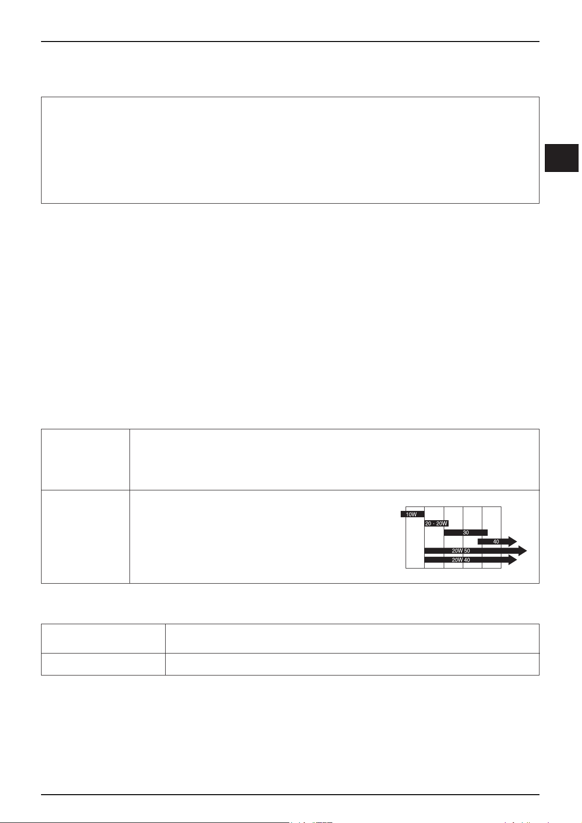
ENGINE OIL CHANGE
NOTE
•To completely and rapidly drain engine oil, warm up
engine and erect the motorcycle on its side stand.
● Loosen the oil drain plug bolt and drain engine oil.
● Operate the kick starter arm several times to remove
the remaining oil from the engine.
● Tighten the oil drain plug bolt.
TORQUE VALUE : 2.0-3.0 kgf·m
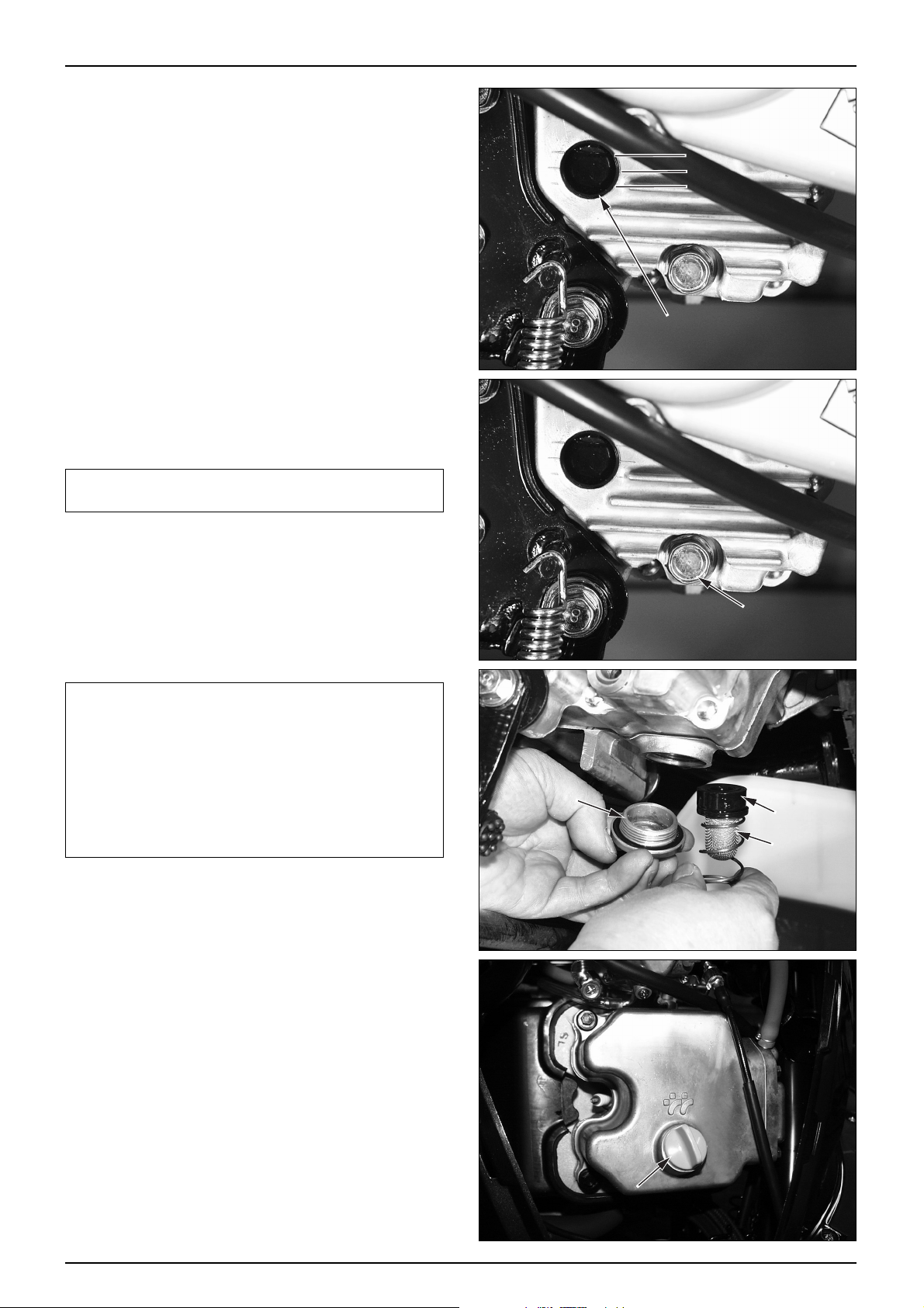
CAUTION
•It is extremely important to replace oil filter or clean
the oil filter screen at the first maintenance interval
(after 1,000Km).
•Clean the oil filter screen every 4,000Km.
•Clean the filter screen with fresh cleaning oil.
•Check the hole cap O-ring for satisfactory condition.
•Tighten the hole cap with specified tightening torque.
TORQUE VALUE : 1.5 kgf·m
● Loosen the special screw, remove the plug maintenance
cover.
● Fill the recommended oil after opening oil filter cap of
cylinder head cover .
OIL CAPACITY : 1.1ℓ(After disassembly)
0.9ℓ(After Oil change with Oil in
the Oil hose removed)
0.8ℓ(After Oil filter change)
0.75ℓ(After Oil change)
● API service classification : SE, SF , SH grade.
● Start the engine and keep it idle for a few minutes.
● Stop the engine and check the oil level. If the oil level
is low , add the recommended engine oil.
● Check on oil leaks.
2-3
LUBRICA TION
UPPER LINE
PROPER LINE
LOWER LINE
SIGHT GLASS
OIL DRAIN PLUG
TAPPET ADJUSTING
HOLE CAP
OIL PICK
UP COLLAR
OIL FILTER
SCREEN
OIL FILTER CAP
Page 22
OIL FILTER ELEMENT CHANGE
●Drain engine oil. (⇨2-3)
●Loosen the 3 flange bolts securing the oil filter cover,
remove the oil filter cover.
●Remove the oil filter element and oil filter spring.
●Change the oil filter element with a new one.
●Check if the oil filter seal is in good condition.
●Assemble the filter element spring and filter cover, and
tighten bolts.
TORQUE VALUE : OIL FILTER COVER 1.1kgf·m
NOTE
•Always use a genuine oil filter element.
•Be sure to replace the oil filter seal when removing oil
filter element.
•Be careful not to lose the oil filter spring when
assembling the oil filter element.
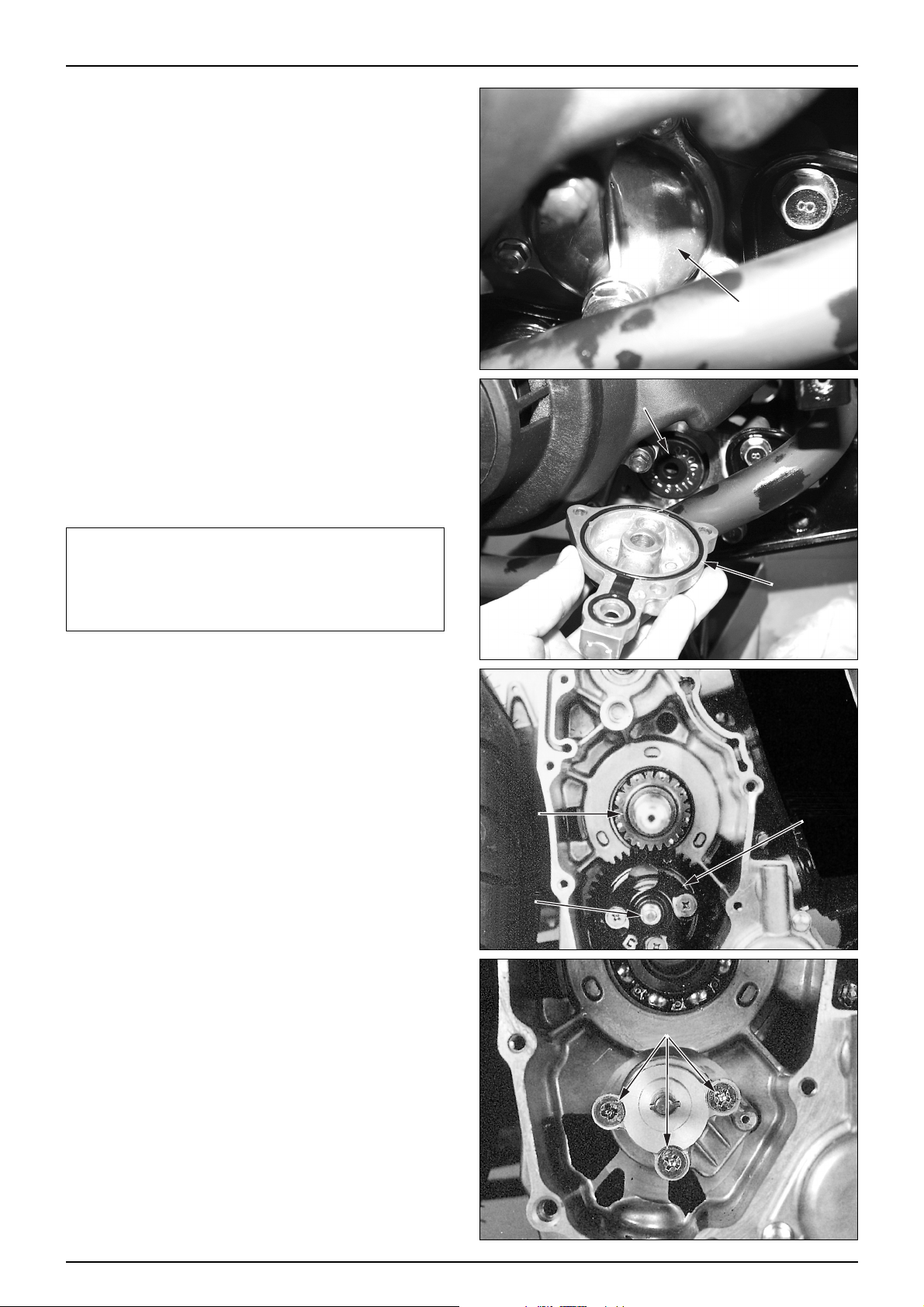
OIL PUMP
REMOV AL
●Remove the following parts :
-Rear cushion lower bolt (⇨13-7)
-Muffler (⇨4-12)
-Rear swing arm (⇨13-8)
-Rear caliper (⇨14-6)
-Shroud (⇨8-2)
-Cooling fan (⇨8-2)
-A.C. generator (⇨8-2)
-RH. crankcase cover (⇨8-4)
-Starter driven gear (⇨8-6)
-Reduction gear (⇨8-5)
-Starting clutch assembly (⇨8-6)
●Loosen the oil pump driven gear setting nut.
●Remove the oil pump driven gear.
●Remove the oil pump drive gear.
●Loosen the 3 flat screws securing the oil pump.
●Remove the oil pump.
2-4
LUBRICA TION
OIL FILTER COVER
DRIVE
GEAR
NUT
ELEMENT
OIL FILTER SEAL
DRIVEN GEAR
FLAT SCREW
Page 23
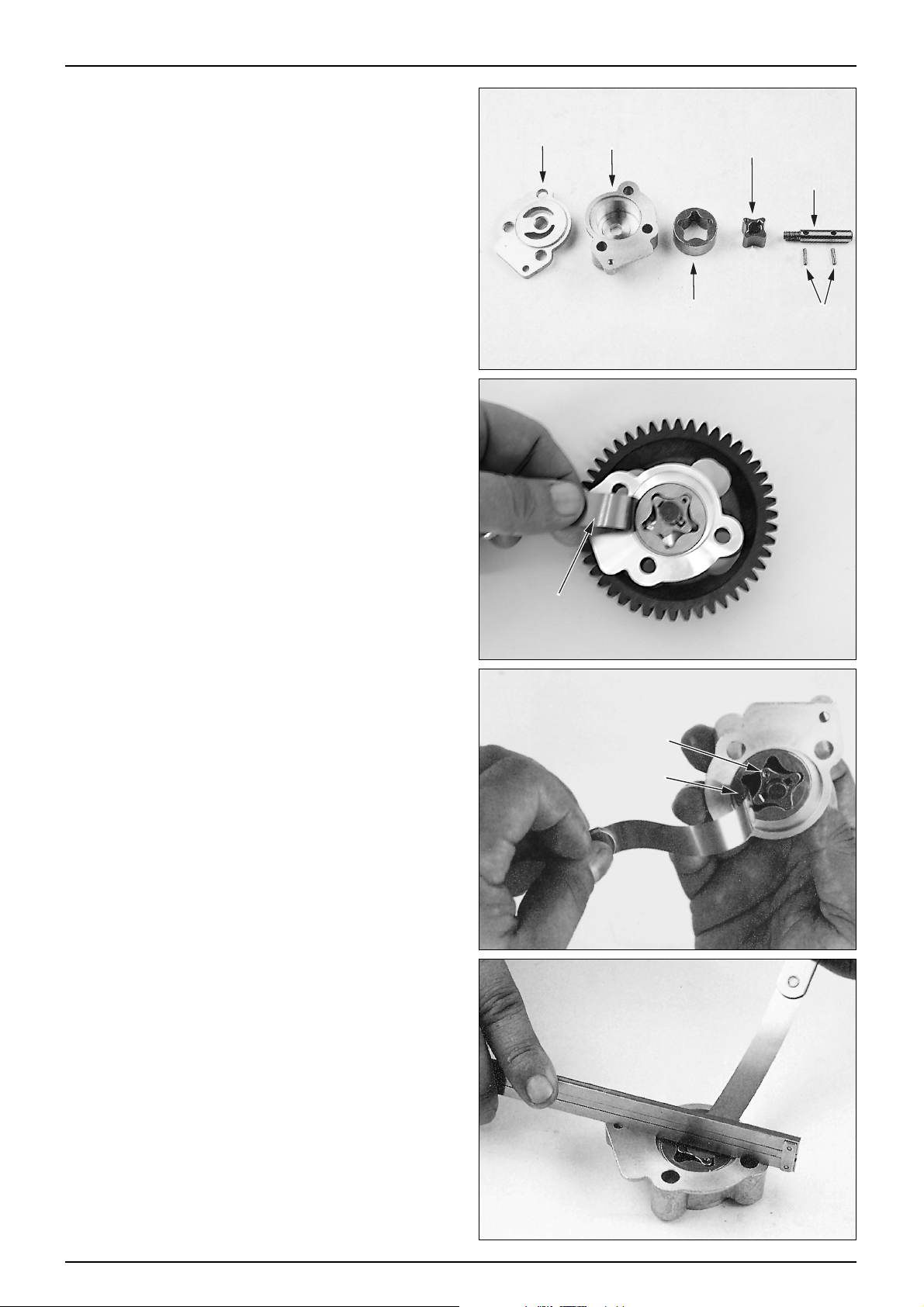
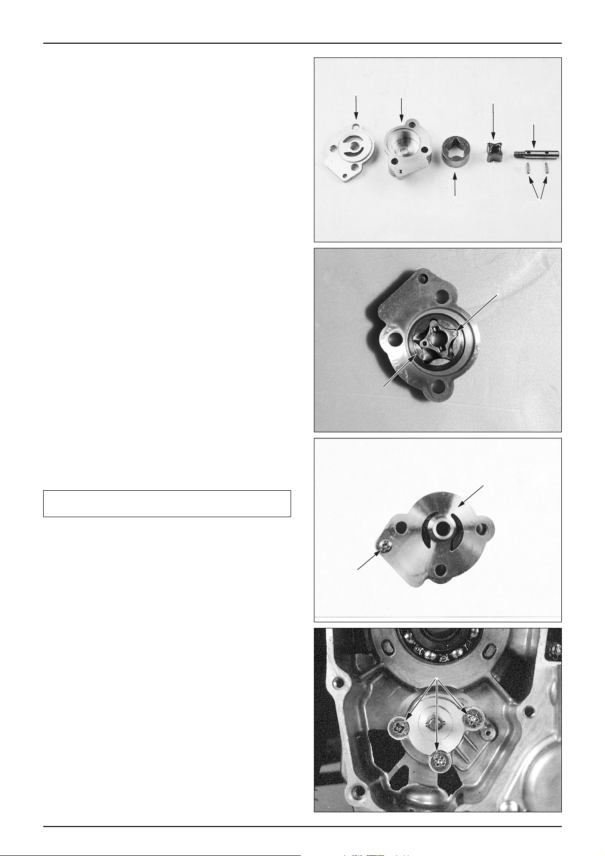
OIL PUMP DISASSEMBLY
●Loosen the screw securing the oil pump plate.
●Remove the oil pump body and the oil pump plate.
●Clean the oil pump body, inner and outer rotors with
fresh cleaning oil.
OIL PUMP INSPECTION
●Assemble the inner and outer rotors to the oil pump
body .
●Measure the pump body clearance.
SERVICE LIMIT : 0.23mm
TOOL : FEELER GAUGE
●Measure the rotor tip clearance.
SERVICE LIMIT : 0.18mm
●Measure the pump side clearance
SERVICE LIMIT : 0.12mm
2-5
LUBRICA TION
PUMP PLATE
PUMP BODY
OUTER ROTOR
INNER ROTOR
PUMP SHAFT
ROLLER2.5x11.8
FEELER GAUGE
INNER ROTOR
OUTER ROTOR
Page 24
2-6
LUBRICA TION
OIL PUMP ASSEMBLY
●Clean all parts with fresh cleaning oil.
●Install the inner and outer rotors to the pump body.
●Assemble the pump shaft with setting pin.
●Install the oil pump plate to the pump body.
●Tighten the pan screw.
NOTE
•After installing, check the oil pump to operate
smoothly .
OIL PUMP INST ALLATION
●Install the oil pump to the RH. crankcase.
●Install the following parts.
-Oil pump drive gear and driven gear .
-Starting clutch assembly . (⇨8-8)
-Starter driven gear and reduction gear (⇨8-6)
-A.C. generator (⇨8-2)
-RH. crank case cover (⇨8-6)
-Shroud and cooling fan (⇨8-2)
-Rear swing arm (⇨13-8)
-Rear caliper (⇨14-6)
-Muffler (⇨4-12)
PUMP PLATE
PUMP BODY
OUTER ROTOR
INNER ROTOR
PUMP SHAFT
ROLLER2.5x11.8
INNER ROTOR
OUTER ROTOR
PUMP PLATE
PAN SCREW
FLAT SCREW
Page 25
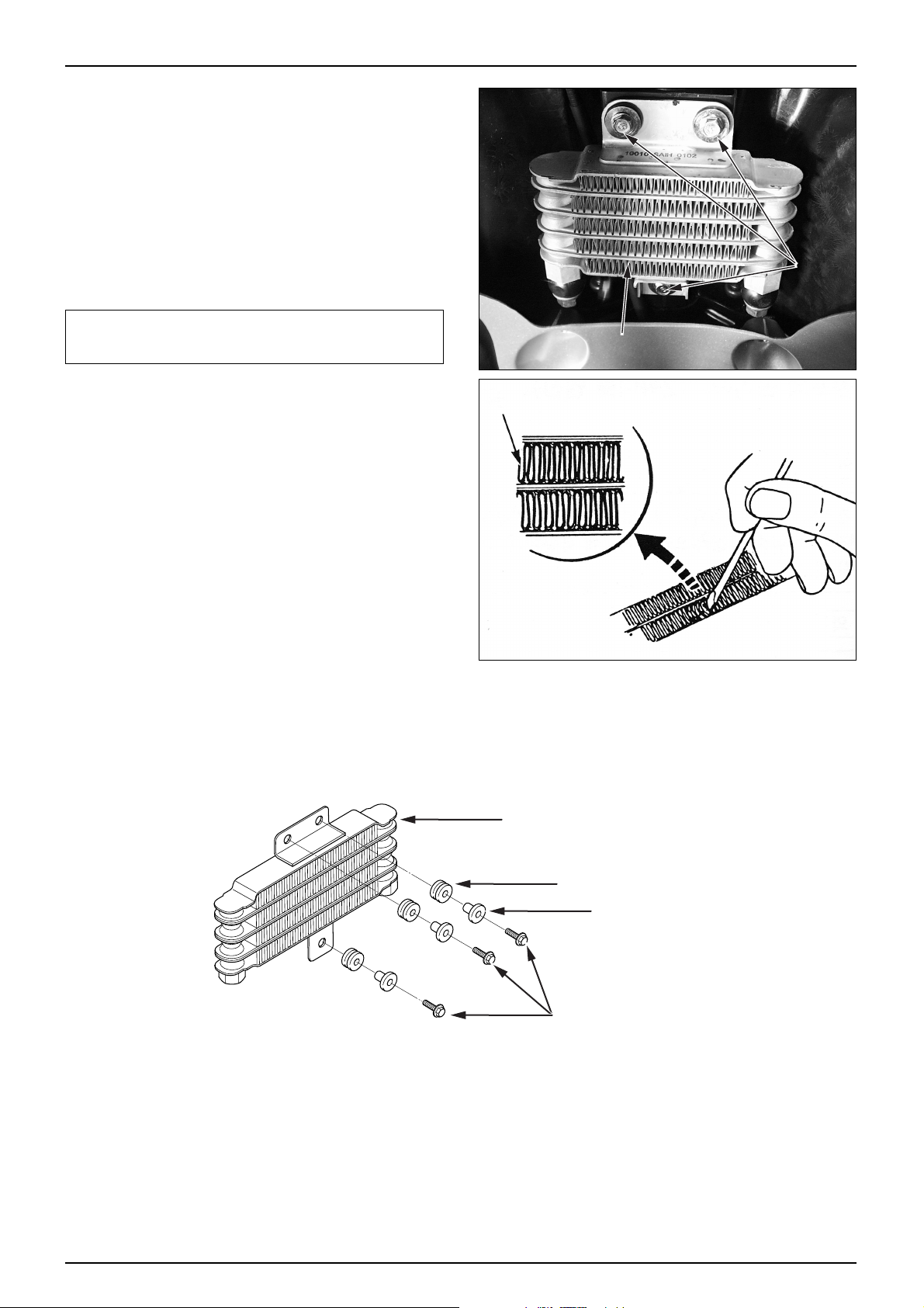
RADIATOR
REMOV AL
●Remove the front cover. (⇨4-3)
●Remove the front wheel. (⇨12-5)
●Loosen the 2 oil bolts and the 4 drain cock packings
from the main pipe bracket.
●Loosen the 3 flange bolts securing the radiator.
●Remove the radiator.
CAUTION
•Be careful not to damage the radiator when removing it.
•Pay attention not to turn over the vehicle.
INSPECTION
●Check the oil line connections for leaks.
●Check the oil cooler for bent or collapsed fins.
Straighten the bent or collapsed fins with a suitable,
small, blade-type screw driver if necessary .
●Check the air passages for clogging or restriction. Blow
dirt out from between core fins with compressed air or
wash off dirt with water .
●After installing, start the engine and check for leak. Stop
the engine and check the oil level.
2-7
LUBRICA TION
FLANGE
BOLT
RADIATOR
FIN
OILRADIATOR
RADIATORRUBBER
RADIATORCOLLAR
FLANGEBOLT
Page 26
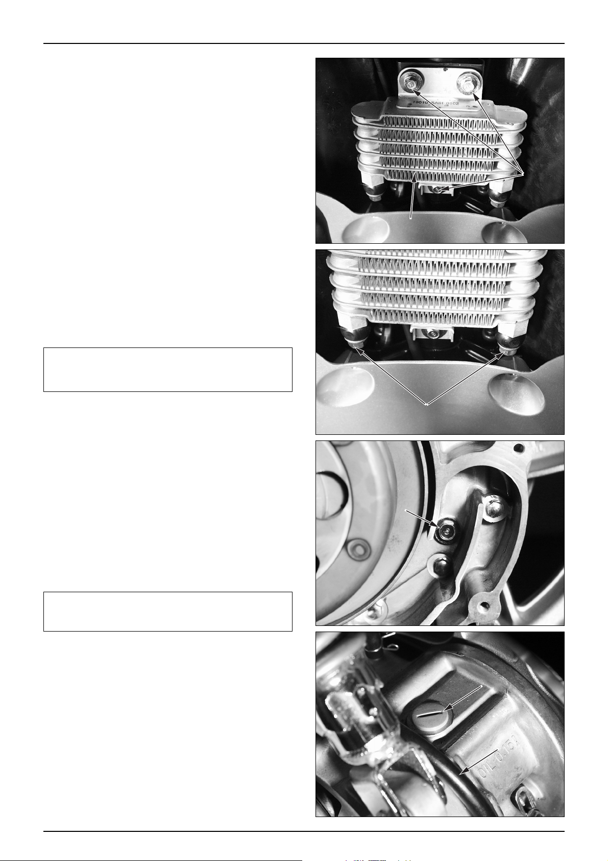
RADIA T OR INSTALLATION
●Tighten the 3 radiator setting flange bolts to the main
pipe bracket.
●Tighten the drain cock packings and oil bolts.
TORQUE VALUE : 3.2kgf·m
●Install the front wheel. (⇨12-9)
●Install the front cover. (⇨4-3)
CAUTION
•Pay attention not to turn over the vehicle.
•When installing the radiator, tighten the oil bolts with
specified tightening torque.
TRANSMISSION OIL INSPECTION
●Remove the LH. crankcase cover. (⇨7-2)
●Check the body and the connection of each engine
component for any leak.
●Remove the oil check bolt and check to see if the oil
overflows from the oil check hole.
●If only the small amount of oil overflows. fill the
recommended transmission oil through the oil filler
hole gradually .
NOTE
•Oil level inspection must be performed in the flat
ground with the vehicle being straight by raising the
main stand.
RECOMMENDED OIL : SAE 80W/90
●Tighten the oil check bolt.
TORQUE VALUE : 0.9 kgf·m
●Start the engine and check for leak.
●Install the LH. crankcase cover. (⇨7-2)
2-8
LUBRICA TION
FLANGE
BOLT
RADIATOR
OIL BOLT
OIL CHECK BOLT
A.C.GENERATOR CAP
BREATHER TUBE
Page 27
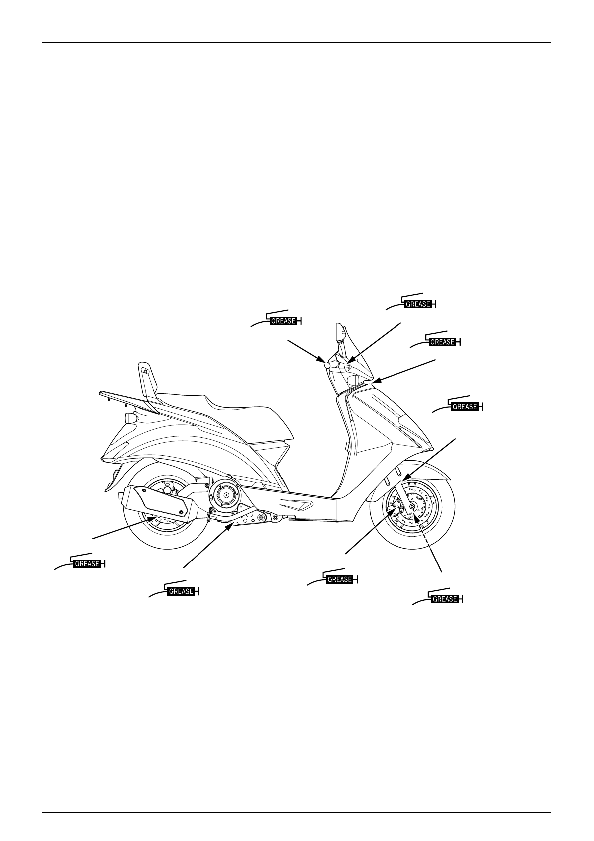
LUBRICATION POINTS
Unless specifically designated, use general grease to
lubricate the lubrication points. For sliding parts not
shown here, add oil or grease.
CONTROL CABLE LUBRICA TION
Remove and clean the upper assembly of the throttle
cable, and apply oil. If the cable has expanded, replace it.
2-9
LUBRICA TION
FRONTBRAKELEVERPIVOT
THROTTLEGRIP
STEERINGHEADBEARING
FRONTFORK
DUSTSEAL
WHEELBEARING/SPEEDOMETERGEAR
BRAKECALIPERBRACKET
SIDE/MAINSTANDPIVOT
WHEELBEARING
Page 28
MEMO
Page 29
3-1
3. INSPECTIONS/ADJUSTMENTS
SERVICE INFORMATION
WARNING
●The exhaust gas contains poisonous substance. Do not keep engine idling in a closed or poorly ventilated place for a
long period of time.
SPECIFICA TIONS
TIRES
3
SERVICE INFORMATION
······
3-1
MAINTENANCE SCHEDULE
··
3-3
FUEL LINE (FUEL TUBE)
······
3-4
THROTTLE GRIP OPERATION
····
3-4
AIR CLEANER
··············
3-4
SPARK PLUG
··············
3-5
VALVE CLEARANCE
········
3-5
CYLINDER COMPRESSION PRESSURE
··
3-6
CARBURETOR IDLE SPEED
····
3-6
BRAKE FLUID
················
3-7
BRAKE PAD/SHOE
··········
3-7
BRAKE SYSTEM
············
3-7
BRAKE LEVER FREE PLAY
··
3-8
HEADLIGHT AIM
············
3-8
SIDE STAND
················
3-8
SUSPENSION
··············
3-9
BOLTS, NUTS, FASTENERS
····
3-9
WHEELS/TIRES
··············
3-10
STEERING HEAD BEARING
··
3-10
THROTTLE GRIP PLA Y 2- 6mm
SP ARK PLUG CR8EH-9
SP ARK PLUG GAP 0.8-0.9mm
IN 0.12±0.02mm
EX 0.12±0.02mm
CARBURETOR IDLE SPEED 1,800±100rpm
CYLINDER COMPRESSION PRESSURE 14±2kgf/㎠㎠( 550rpm )
NOTE
•For information on engine oil and oil filter, refer to sections 2-3 and 2-4
•Stand the main stand prior to beginning work.
VALVE CLEARANCE
COLD TIRE
PRESSURE
TIRE SIZE
MIN, TREAD
DEPTH “”
DRIVER ONL Y
DRIVER AND A
PASSENGER
FRONT TIRE
REAR TIRE
FRONT TIRE
REAR TIRE
FRONT TIRE
REAR TIRE
FRONT TIRE
REAR TIRE
200kPa (2.00kgf/㎠㎠)
200kPa (2.00kgf/㎠㎠)
200kPa (2.00kgf/㎠㎠)
225kPa (2.25kgf/㎠㎠)
120/70 - 12 53k(Tubeless)
130/70 - 12 62k(Tubeless)
0.5mm
0.5mm
Page 30

TORQUE VALUES
SPARK PLUG 1.1kgf·m
CYLINDER HEAD COVER BOLTS 1.0kgf·m
VALVE ADJUSTING NUTS 1.1kgf·m
TIMING HOLE CAP 0.6kgf·m
TOOLS
WRENCH 8X9mm
ADJUST WRENCH
COMPRESSION GAUGE
3-2
INSPECTIONS / ADJUSTMENTS
Page 31

3-3
INSPECTIONS / ADJUSTMENTS
MAINTENANCE SCHEDULE
● Carry out pre-operation check at each scheduled maintenance period based on the information described in the owner’s
manual.
I : INSPECT AND CLEAN, ADJUST, LUBRICATE OR REPLACE IF NECESSARY.
R : REPLACE L : LUBRICATE C : CLEAN
● These instructions are based on the assumption that the motorcycle will be used exclusively for its designed purpose.
Sustained high speed operation, or operation in unusually wet or dusty conditions, will require more frequent service
than specified in the following chart.
* If there are no appropriate type of tools and maintenance data available, or if you do not have mechanical technology
contact authorized maintenance shops, dealers or other designated repair shops for maintenance and inspections.
To ensure safety, inspections and maintenance of these parts must be carried out by authorized maintenance shops,
dealers or other designated repair shops.
NOTE
1. After the odometer reading exceeds 12,000km, repeat maintenance service at intervals indicated in the table.
2. After riding in areas with high humidity or pollution, carry out maintenance service more frequently.
3. Replace every 2 years. Proper technology is required for this job.
*
*
*
*
*
*
*
*
*
*
*
*
*
FUEL LINE(FUEL TUBE)
FUEL FILTER
THROTTLE GRIP OPERATION
AIR CLEANER
SPARK PLUG
VALVE CLEARANCE
TRANSMISSION OIL
ENGINE OIL
ENGINE OIL FILTER
CARBURETOR IDLE SPEED
BRAKE FLUID
BRAKE SHOE/PAD WEAR
BRAKE SYSTEM
BRAKE STOP SWITCH
HEADLIGHT ADJUSTMENT
SIDE ST AND
SUSPENSION
BOLTS, NUTS, FASTENERS
WHEELS/TIRES
STEERING HEAD BEARING
DRIVE BELT
WEIGHT ROLLER
SLIDE PIECE
OIL FILTER SCREEN
MOVABLE DRIVE FACE INNER PART
NOTE 2
NOTE 3
NOTE 3
I
R
I
I
I
R
R
I
I
I
I
I
I
I
R
I
I
I
R
R
I
I
I
I
I
I
I
I
I
I
I
I
I
C
L
I
R
I
I
I
R
R
I
I
I
I
I
I
I
I
I
I
I
I
I
I
C
L
I
R
I
I
I
R
R
R
I
I
I
I
I
I
I
I
I
I
I
I
I
C
L
Every 1,000㎞ : C
FREQUENCY
ODOMETER READING(NOTE 1)
61218
14812REMARK
ITEM
x 1000Km
MONTH
Page 32
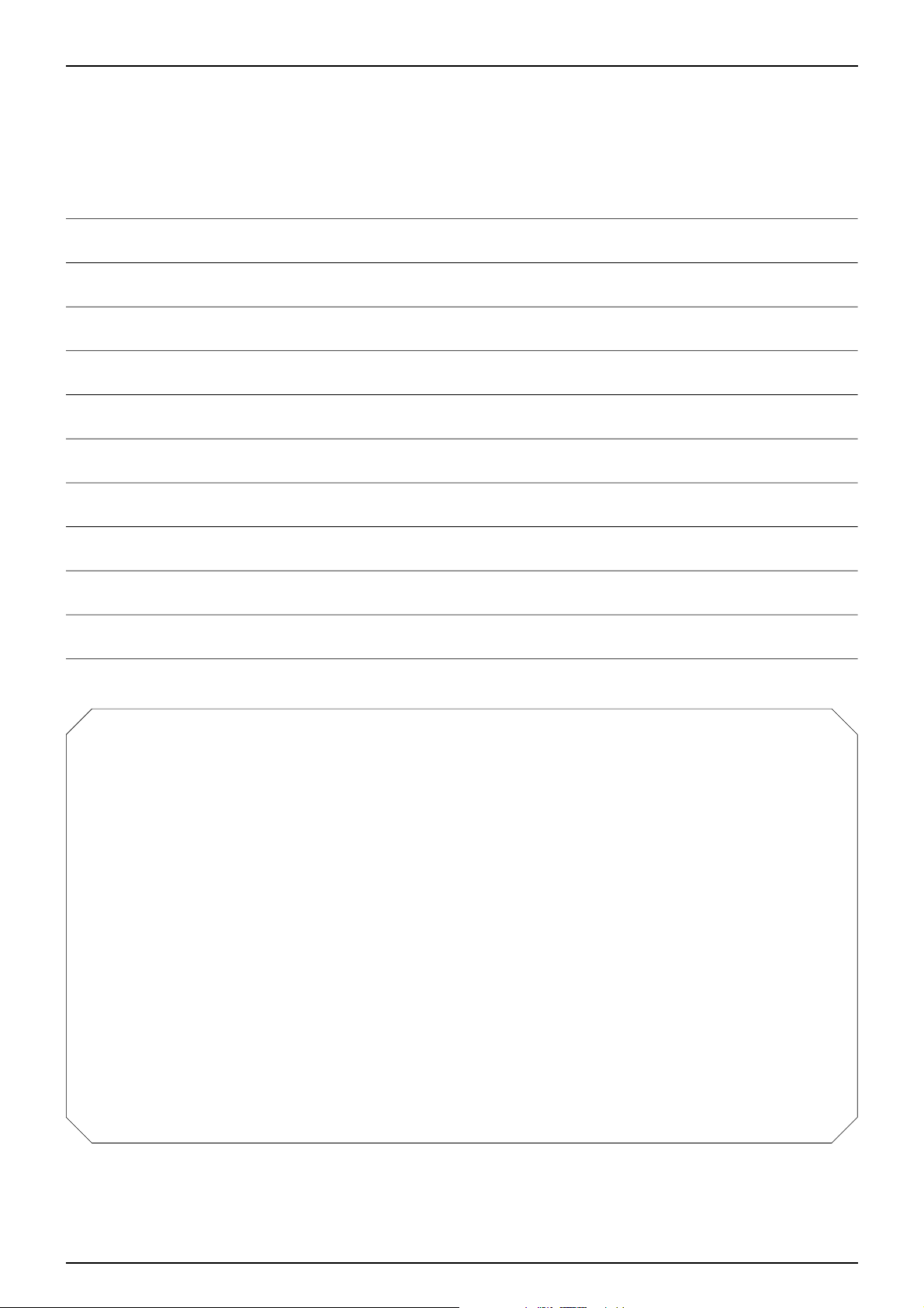
FUEL LINE(FUEL TUBE)
● Remove the luggage box.(⇨4-4)
● Check the fuel tube of the fuel pump connected to the
fuel tank and carburetor. If the fuel tube is cracked,
damaged or leaks, replace it.
THROTTLE GRIP OPERA TION
● Check if the throttle grip operates smoothly in any
steering position.
● If the throttle grip does not operate properly, lubricate
the throttle cable.
● If the throttle grip does not operate properly, check the
throttle cable for aging, damage or kinking.
● Check the throttle grip free play.
FREE PLAY : 2~6mm
● For adjustment, loosen the lock nut and turn adjuster.
● After adjusting, tighten lock nut. After adjustment is
completed, recheck the throttle grip free play .
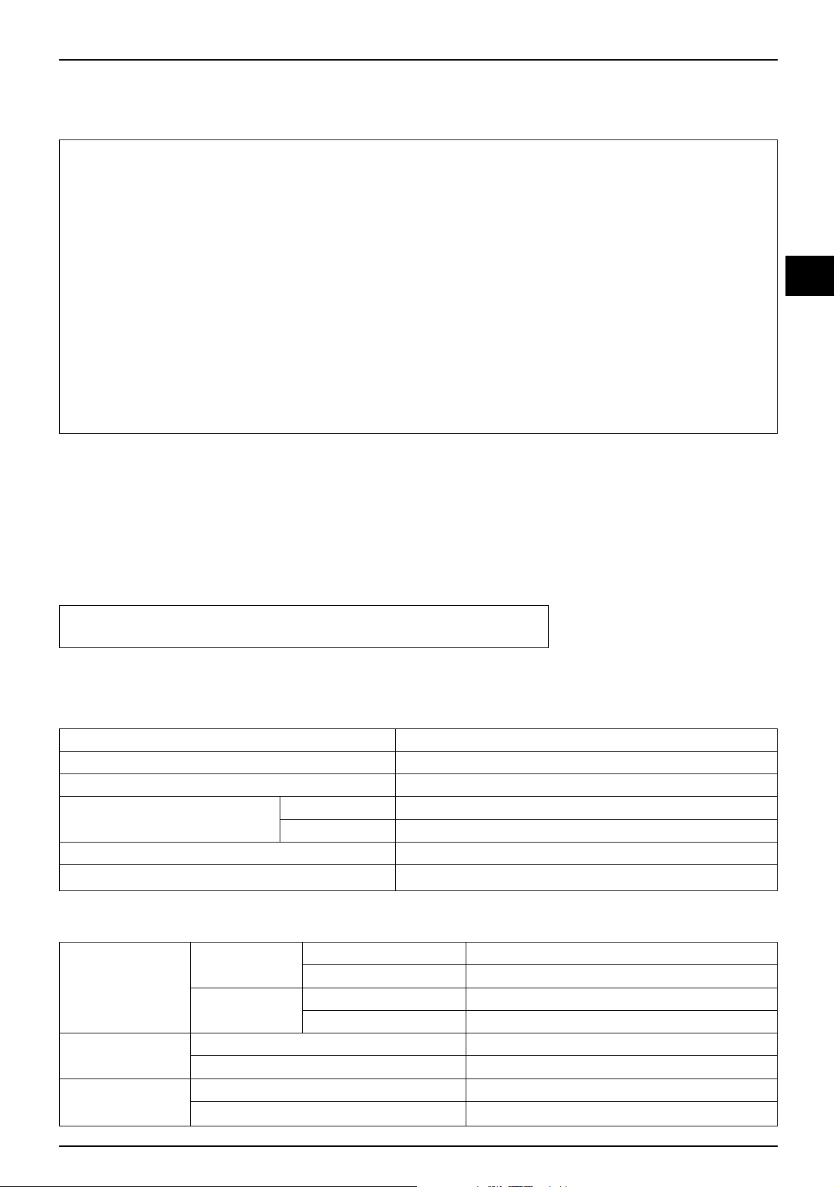
AIR CLEANER
● Release the seat lock by turning the main switch key to
open the seat.
● Loosen the 6 screws securing the air cleaner case cover,
remove it.
● Loosen the 2 screws securing the air cleaner element
holder, remove it.
● Remove the air cleaner element.
● Remove the air cleaner trap comp.
● Wash away any accumulated dust or dirt, by gently
squeezing it in non flammable or high flash point
solvent.
WARNING
•Using gasoline or low flash point solvents for
cleaning parts may result in a fire or explosion.
CAUTION
•Cleaning the element with gasoline or any acid,
alkaline, or organic, volatile type oil may cause
improper ignition, deterioration of the element, or a
loosening of the element adhesive.
3-4
INSPECTIONS / ADJUSTMENTS
FUEL PUMP
FUEL TUBE
SCREW
AIR CLEANER
ELEMENT
AIR CLEANER
TRAP
SCREW
Page 33

● Be sure to allow the element to dry thoroughly before
applying oil. Otherwise, the oil will be diluted by the
and the filtering ability of the filter will be much less
effective.
● Spread clean #80~90 gear oil on the element, rubbing
inthoroughly over the surface with both hands, and then
squeeze out any excess oil.
CAUTION
•Using air filter oil when riding in extremely dusty
conditions prevents premature engine wear due to
dust/dirt drawn into the engine. Apply air filter oil to
the entire surface of the element and rub it with both
hands to saturate the element with oil. Squeeze out
excess oil.
SPARK PLUG
● Remove the plug maintenance cover.
● Remove the spark plug cap and disassemble the plug.
● Check the plug for damage, contamination or deposits.
● If the spark plug is severely contaminated or damaged,
raplace with a new one. If the plug can be reused after
removing only the carbon, use plug cleaner and wire
brush to clean the plug.
● Always use a feeler gauge to check the gap.
GENUINE PLUG : CR8EH-9
SPARK PLUG GAP : 0.8~0.9mm
TORQUE VALUE : 1.1 kgf·m
CAUTION
•Make sure there is no dirt or debris on the seat of the
spark plug hole before inserting the spark plug.
•To prevent damage to the cylinder head, hand-tighten
the spark plug before using a wrench to tighten to the
specified torque.(torque : 14kgf·m)
•Do not overtighten the spark plug.
VALVE CLEARANCE
● Remove the following parts.
-Luggage box. (⇨4-4)
-Center cover. (⇨4-5)
● Loosen the 4 cylinder head bolts.
NOTE
•Inspect and adjust the valve clearance when the
engine is cool. (under 35°C / 95°F)
•Remove the cylinder head cover.
•Turn the flywheel counterclockwise, and align the
“T” mark on the flywheel with the index mark on
the RH. crank case cover .
•The piston at this time must be at the top dead center
of the compression stroke.
● Measure valve clearance with a feeler gauge.
VALVE CLEARANCE : Intake : 0.12±0.02mm
Exhaust : 0.12±0.02mm
3-5
INSPECTIONS / ADJUSTMENTS
TIMING CHECKING
RH. SHROUD
→
→→
CHECK GAP,
DEPOSITS
CHECK FOR
CRACKS
0.8mm~0.9mm
CHECK WASHER
FOR DAMAGE
CYLINDER HEAD
COVER
Page 34

● Loosen the lock nut with a valve wrench, and set valve
clearance to a prescribed level by turning the adjusting
screw with a valve adjusting wrench.
● After setting clearance to the prescribed level, hold the
adjuster screw with a valve adjusting wrench, and
tighten the lock nut.
TORQUE VALUES : 1.1kgf·m
TOOLS : WRENCH 8X9mm
ADJUSTING WRENCH B
FEELER GAUGE
● Measure the valve clearance again.
● Install the cylinder head cover and tighten the bolts.
TORQUE VALUES : 1.0 kgf·m
CYLINDER COMPRESSION PRESSURE
● Start and warm up the engine.
● Remove the plug maintenance cover.
● Stop engine, and remove the spark plug cap and spark
plug.
● Install a compression gauge.
● Open the throttle completely, and crank the engine with
the starter motor until the gauge reading rising.
TOOL : COMPRESSION GAUGE
NOTE
•The maximum reading is usually reached within 4~7
seconds.
COMPRESSION PRESSURE : 13.8 kg/cm
2
● If the pressure is low, check the following:
-Inadequate valve clearance adjustment
-Valve leakage
-Leakage from the cylinder head gasket
-Piston/cylinder worn
● If pressure is high, check the following:
-Carbon deposits on the piston head, and cylinder head.
CARBURETOR IDLE SPEED
● Remove the plug maintenance cover . (⇨4-5)
● Check the idle speed and adjust if necessary by turning
the throttle stop screw .
NOTE
•Verify all engine adjustments satisfy specifications.
Make adjustments, if necessary .
•Heat the engine to make accurate idling inspection
and adjustment. Stand the vehicle on the main stand.
•Turn the throttle stop screw and make adjustments to
prescribed idling speed.
3-6
INSPECTIONS / ADJUSTMENTS
ADJUSTER
WRENCH
FEELER
GAUGE
SPARK PLUG
COMPRESSION
GAUGE
THROTTLE STOP SCREW
Page 35
BRAKE FLUID
● Loosen the 3 screen setting screws securing the wind
screen.
● Remove the oil cup cap covers.
● Check the oil level inside the front/rear brake
reservoirs. If the oil level is near the lower limit line,
remove the reservoir diaphragms and fill DOT 3 and
DOT 4 brake fluid to the top limit line.
● If the brake fluid reaches the lower limit line, check the
entire brake system for leaks.
CAUTION
•Brake fluid will damage painted, plastic or rubber
parts.
•Mixing incompatible fluids can impair braking
efficiency.
•Foreign materials can clog the system, causing a
reduction or complete loss of braking ability.
•A leak in the brake system can lead to reduced
braking effiency and possible loss of braking ability.
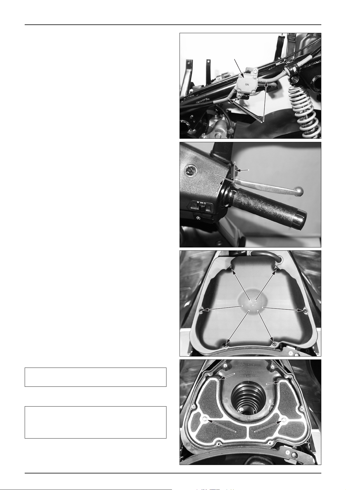
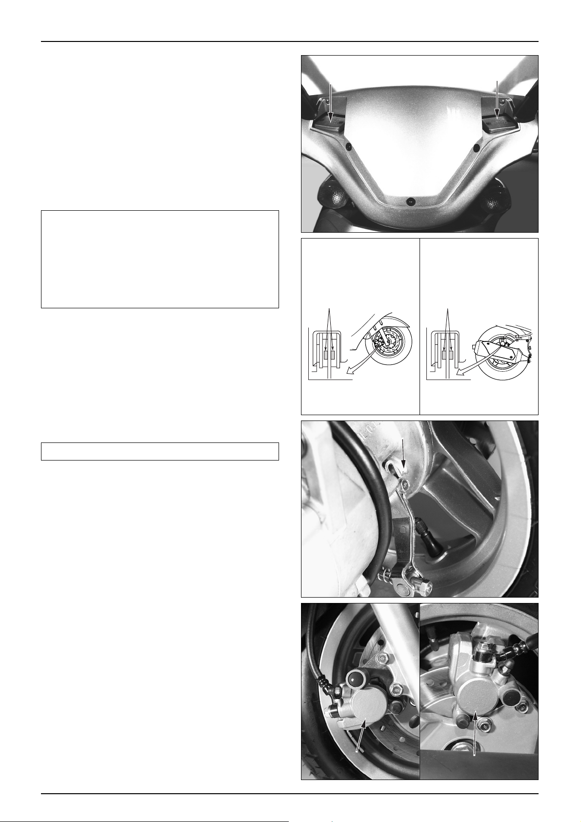
BRAKE PAD/SHOE
BRAKE P AD REPLACEMENT
● Check the brake pads for wear.
● If the red mark on the pad reaches the brake disk,
replace the pads.
NOTE
•Replace the brake pads in sets.
PARKING BRAKE SHOE REPLACEMENT
● If the arrow mark of the wear limit aligns with the ‘△’
mark when the parking brake lever is tightly depressed,
it indicates the brake lining has reached the service
limit. Replace the brake shoes.
BRAKE SYSTEM
● Check the front brake hose for cracks or damage. If any
leaks are found, replace immediately .
● Check the brake rod for looseness or damage, and
replace it if necessary .
3-7
INSPECTIONS / ADJUSTMENTS
FRONT
MASTER CYLINDER
<FRONT>
WEARLIMITLINE
REAR
MASTER CYLINDER
<REAR>
WEARLIMITLINE
"△" MARK
FRONT CALIPER
REAR CALIPER
Page 36

BRAKE LEVER FREE PLAY
● Check the free play after pulling the lever.
FRONT : 10~20mm
REAR : 10~20mm
PARKING BRAKE FREE PLAY ADJUSTMENT
● Turn the adjuster nut to adjust the free play.
● After initial adjustment, check the operation of the
parking brake light switch. Make additional
adjustments, if necessary .
HEADLIGHT AIM
● Adjust the headlight beam level by operating the
adjusting screw located on the upper side of the front
fender.
NOTE
•Adjust the beam level according to local laws and
regulations.
•Improper beam level adjustment may blind
oncoming drivers, or may incorrectly light the road
ahead.
SIDE STAND
● Erect the main stand.
● Pull the lower end of the side stand, and see if it moves
freely .
● If the side stand does not move smoothly, apply grease
to the pivot area.
● If the side stand moves too freely, check the side stand
spring.
● Check the axial movement of the side stand.
3-8
INSPECTIONS / ADJUSTMENTS
ADJUSTER NUT
VERTICAL
ADJUSTING SCREW
HORIZONTAL
ADJUSTING SCREW
Page 37

● Check the side stand ignition cut-off switch :
-Put the side stand up.
-Start the engine.
-Lower the side stand. The engine should stop as you
put the side stand down.
● If there is a problem with the system, check the side
stand switch.
SUSPENSION
NOTE
•Do not ride motorcycle with an unsatisfactory
suspension. Loose or worn suspension parts will lead
to deterioration in the vehicle’s safety and operation
efficiency.
FRONT WHEEL
● Hold the brake lever, and compress the front cushion
up and down several times to check the operating
conditions.
● Check the front fork for oil leakage, parts damage or
looseness.
REAR WHEEL
● Compress the near cushion up and down several times
to check the operating conditions.
● Check the rear fork for oil leakage, parts damage or
looseness.
BOL TS, NUTS, FASTENERS
● Check all nuts and bolts of the frame during the regular
maintenance to check if they meet the prescribed
torque value.
● Check all pins, clips, hose clamps and cable stays.
3-9
INSPECTIONS / ADJUSTMENTS
SIDE STAND
SWITCH
Page 38

WHEELS/TIRES
NOTE
•Check the tire pressure when the tires have been
cooled off. Check the tread (the part making contact
with the road surface) and side for wear, cracks or
damage. Replace damaged tires.
ST ANDARD PRESSURE
● Check the tread depth at the tire center.
● If the tread depth has reached the service limit, replace
the tire.
SERVICE LIMIT :0.5mm
STEERING HEAD BEARING
NOTE
•Check the cable if it interferes with the handle
operation.
● Lift the front wheel and check if the handle moves right
and left smoothly. If the handles move heavily, check if
the cable or electric cord interferes with the handle. If
the handle moves satisfactorily, adjust the steering head
bearing.
3-10
INSPECTIONS / ADJUSTMENTS
FRONT WHEEL
2.00(200)
2.00(200)
REAR WHEEL
2.00(200)
2.25(225)
ITEM
DRIVER ONLY
DRIVER AND A PASSENGER
㎏f/㎠ (kpa)
TIRE PRESSURE GAUGE
WEAR INDICATOR LOCATION MARKING
Page 39

4-1
4. EXTERNAL PARTS
SERVICE INFORMATION
NOTE
● This section describes external parts removal/installation.
● Do not apply unreasonable force when disassembling covers, to prevent possible damage.
● A muffler is hot. Do not service it immediately after the engine is stopped.
4
SERVICE INFORMATION
····
4-1
MAINTENANCE PRECEDURE
····
4-2
EXTERNAL PARTS
REMOVAL / INSTALLATION··4-3
MUFFLER
················
4-12
Page 40
4-2
EXTERNAL P ARTS
2
4 31316
21
17
11
8
9
9
10 6 5
12
15
20
7
22 14
1
19
18
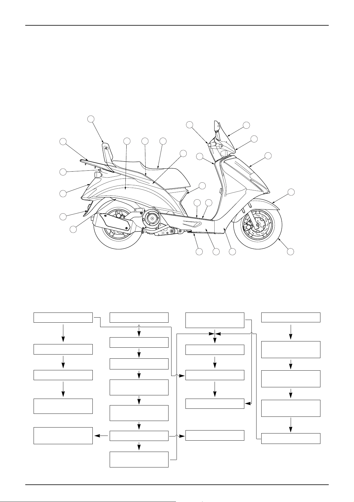
MAINTENANCE PROCEDURE
NAMES OF FRAME COVERS
● This chart shows arrows connected in the order of disassembling covers.
①
FRONT COVER
② FRONT FENDER
③
FRONT WHEEL
④
FRONT UNDER
COVER
⑪
REAR COMBINA TION
LIGHT
⑤ SEAT
⑥ LUGGAGE BOX
⑧ REAR CENTER
COVER
⑨ REAR CARRIER
/ BACK REST
⑫ UPPER BODY
COVR
⑩ BODY COVER
⑦
CENTER COVER
⑬ FLOOR SIDE
COVER
⑭ FLOOR PANEL
⑮ INNER BOX
⑯ UNDER COVER
⑰ REAR FENDER
⑱ WIND SCREEN
⑲ FRONT HANDLE
COVER
⑳ REAR HANDLE
COVER
REAR WHEEL
MUDGUARD
BA TTERY COVER
Page 41

4-3
EXTERNAL P ARTS
SPECIALSCREW
SPECIALSCREW
SPECIALSCREW
SPECIALSCREW
FRONTCOVER
SPECIALSCREW
SPECIALSCREW
FRONTFENDER
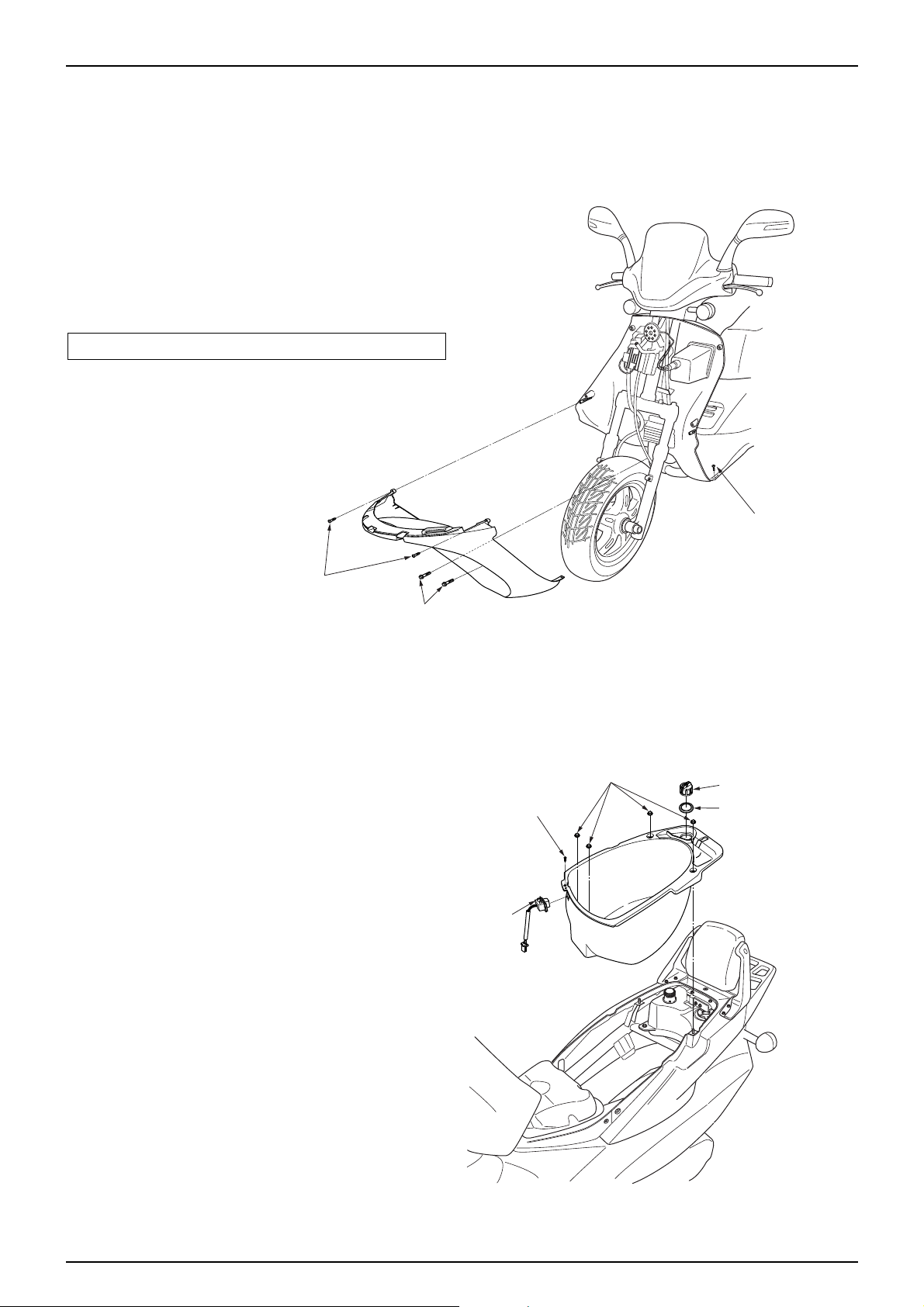
FRONT COVER
● Loosen the 4 special screws securing the inner box.
● Loosen the special screw securing the front of the front
cover.
● Loosen the 2 special screws securing the front under
cover.
● Draw the upper part of the front cover to remove it.
● Disconnect the headlight wiring and remove the
front cover.
● Loosen the 4 flange bolts securing the headlight,
remove the headlight.
● Loosen the 4 tapping screws securing the top cover,
remove the front protector .
● Install in the reverse order of removal.
FRONT FENDER
● Loosen the oval screw securing the speedometer gear
box, remove the speedometer cable.
● Remove the wire grommet from the front fender.
● Loosen the 2 special screws securing the LH. front
cushion.
● Loosen the 2 special screws securing the RH. front
cushion.
● Install in the reverse order of removal.
Page 42
4-4
EXTERNAL P ARTS
TAPPINGSCREW
FLANGEBOLT
SPECIALSCREW
OPENSTAYNUT
FUELTANKCAP
FUELGUIDERUBBER
SCREW
TRUNKLAMP
FRONT UNDER COVER
● Remove the front fender. (⇨4-3)
● Remove the front wheel. ( ⇨12-5)
● Loosen the 4 tapping screws securing the inner box.
● Remove the floor mat, and loosen the 2 special screws
securing the front of the floor panel.
● Loosen the 2 flange bolts securing the frame under
cover bracket.
● Remove the front under cover.
● Install in the reverse order of removal.
NOTE
•Pay attention not to turn over the vehicle.
LUGGAGE BOX
● Release the seat lock by turning the main switch key to
open the seat.
● Loosen the 4 open stay nuts.
● Loosen the fuel tank cap, remove the fuel guide rubber.
● Disconnect the trunk lamp wiring.
● Remove the luggage box.
● Loosen the tapping screw securing the luggage box,
remove the trunk lamp.
● Install in the reverse order of removal.
Page 43

4-5
EXTERNAL P ARTS
SEAT
WASHERSCREW
SPECIALSCREW
PLUGMAINTENANCECOVER
CENTERCOVER
FLANGEBOLT
HINGEPIN
SPECIALSCREW
REARCENTERCOVER
SPECIALSCREW
WASHERSCREW
RH.REARWINKERASSEMBLY
REFLEXREFLECTOR
SPECIALSCREW
SPECIALSCREW
LH.REARWINKER
ASSEMBLY
WASHERSCREW
CENTER COVER
● Release the seat lock by turning the main switch key to
open the seat.
● Loosen the flange bolt securing the frame, and remove
the hinge pin, and then remove the seat.
● Loosen the plug maintenance cover setting special
screw securing the center cover, remove the plug
maintenance cover .
● Loosen the 2 washer screws securing the body cover.
● Loosen the special screw securing the front of the floor
panel.
● Draw the upper part of the center cover to remove it.
● Install in the reverse order of removal.
REAR CENTER COVER
● Loosen the 4 special screws securing the body cover.
● Remove the rear center cover, disconnect the RH./LH.
winker wiring.
● Loosen the RH./LH. winker setting washer screws
securing the rear center cover, remove the RH./LH.
winker.
● Remove the rear reflex reflector securing the rear
center cover .
● Install in the reverse order of removal.
Page 44

4-6
EXTERNAL P ARTS
SPECIALBOLT
BACKREST
FLANGEBOLT
REARCARRIER
FLANGEBOLT
SPECIALSCREW
SPECIALSCREW
BODYCOVERCLIP
UPPERBODYCOVER
REARREFLECTOR
TAPPINGSCREW
TAPPINGSCREW
SPECIALSCREW
BODYCOVERCLIP
BODYCOVER
REAR CARRIER/BACK REST
● Remove the rear center cover. (⇨4-5)
● Loosen the 2 flange bolts(R/L) securing the frame.
● Loosen the 2 flange bolts(R/L) securing the rear carrier.
● Remove the rear carrier.
● Loosen the 4 back rest setting special bolts(R/L),
Remove the back rest.
● Install in the reverse order of removal.
BODY COVER/UPPER BODY COVER
● Release the seat lock by turning the main switch
key to open the seat.
● Remove the following parts.
-Luggage box (⇨4-4)
-Center cover (⇨4-5)
-Rear center cover (⇨4-5)
-Rear carrier (⇨4-6)
-Back rest (⇨4-6)
● Loosen the 4 special screw (R/L) securing the floor
panel.
● Loosen the 2 special screw (R/L) securing the
frame, disconnect the rear combination light wiring.
● Loosen the 2 body cover clips (R/L) securing the
rear fender.
● Draw the upper part of the body cover to remove it.
● Loosen the 2 washer screws securing the body
cover, remove the rear combination light.
● Loosen the 4 tapping screws securing the body
cover, remove the rear reflector.
● Loosen the 2 tapping screws (R/L) and 2 body
cover clips securing the body cover, remove the
upper body cover.
● Loosen the 2 body cover clips (R/L) securing the
body cover, remove the RH./LH. body cover.
● Install in the reverse order of removal.
Page 45

4-7
EXTERNAL P ARTS
TAPPINGSCREW
REARCOMBINATIONLIGHT
WASHERSCREW
BODYCOVER
SPECIALSCREW
BODYCOVERCLIP
LH.FLOORSIDECOVER
SPECIALSCREW
REAR COMBINATION LIGHT
● Release the seat lock by turning the main switch key to
open the seat.
● Remove the seat.
● Remove the following parts.
-Luggage box (⇨4-4)
-Center cover (⇨4-5)
-Rear center cover (⇨4-5)
-Rear carrier (⇨4-6)
-Back rest (⇨4-6)
-Body cover (⇨4-6)
● Loosen the 2 washer screws securing the body
cover, remove the rear combination light.
● Install in the reverse order of removal.
FLOOR SIDE COVER
● Remove the floor mat.
● Loosen the 2 special screws (R/L) securing the front
part of the front under cover .
● Remove the 4 body cover clips (R/L) securing the floor
panel
● Loosen the 2 special screws (R/L) securing the rear
part of the floor panel.
● Loosen the 2 special screws (R/L) securing the side of
the floor panel.
● Remove the RH./LH. floor side cover.
● Install in the reverse order of removal.
Page 46
4-8
EXTERNAL P ARTS
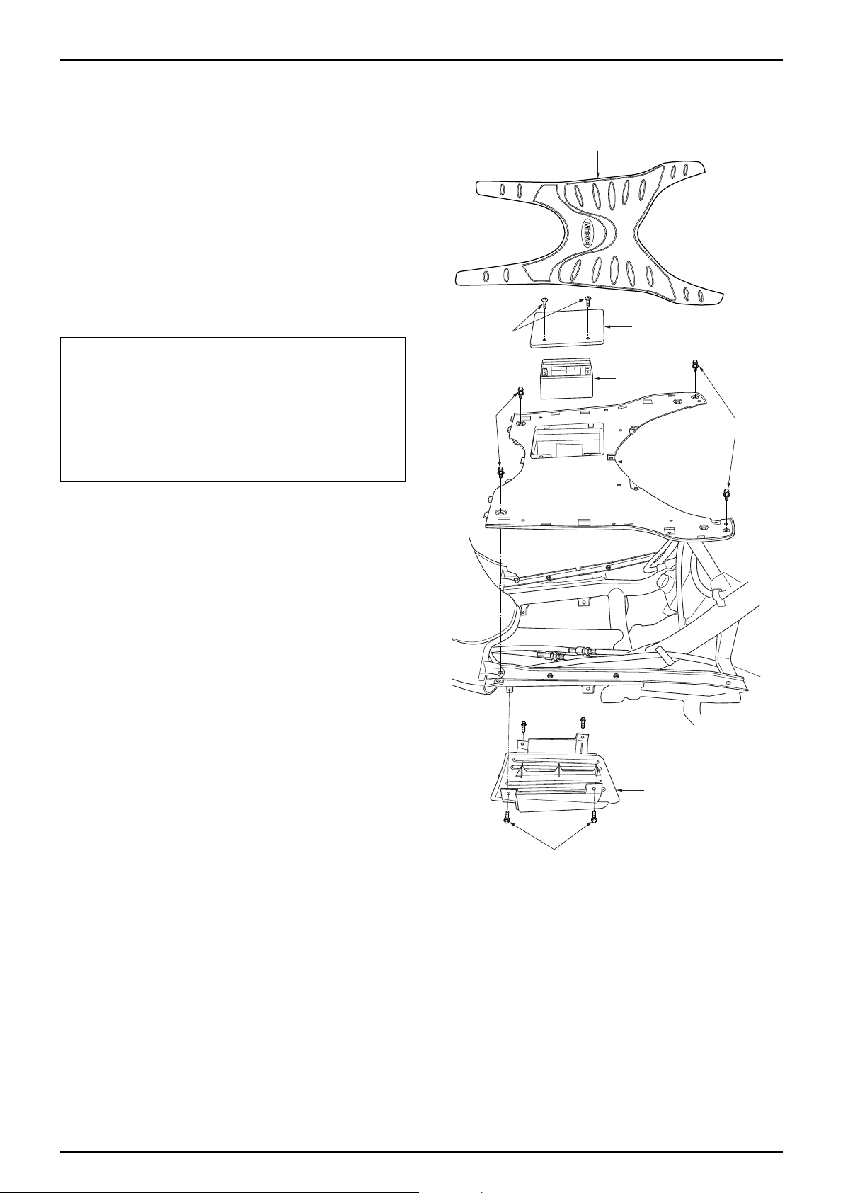
FLOORMAT
TAPPINGSCREW
BATTERYCOVER
FLOORPANEL
UNDERCOVER
SETTINGSCREW
BATTERY
WASHERBOLT
WASHERBOLT
FLOOR PANEL
● Release the seat lock by turning the main switch key to
open the seat.
● Remove the following parts.
-Seat and center cover (⇨4-5)
-Rear carrier and back rest (⇨4-6)
-Floor mat
-Body cover (⇨4-6)
-RH./LH. floor side cover (⇨4-7)
● Loosen the 2 tapping screws securing the floor
panel, remove the battery cover.
● Disconnect the battery wiring to remove the battery.
CAUTION
•Be sure to remove the negative pole ⊖ side cord
first and the position pole ⊕ side cord next.
•Make sure that terminals do not contact with
other adjacent parts when handling ⊕ / ⊖
terminal.
Contact with other parts may cause spark
resulting in electrical equipment malfunction, fire
and electric shock.
● Loosen the 4 washer bolts (R/L) securing the floor
panel.
● Remove the floor panel from the connecting groove
of the inner box by lifting the rear part of the panel
slightly.
● Install in the reverse order of removal.
UNDER COVER
● Remove the floor side cover. (⇨4-7)
● Loosen the 2 upper cover setting screws (R/L) securing
the frame.
● Remove the under cover.
● Install in the reverse order of removal.
4-8
Page 47
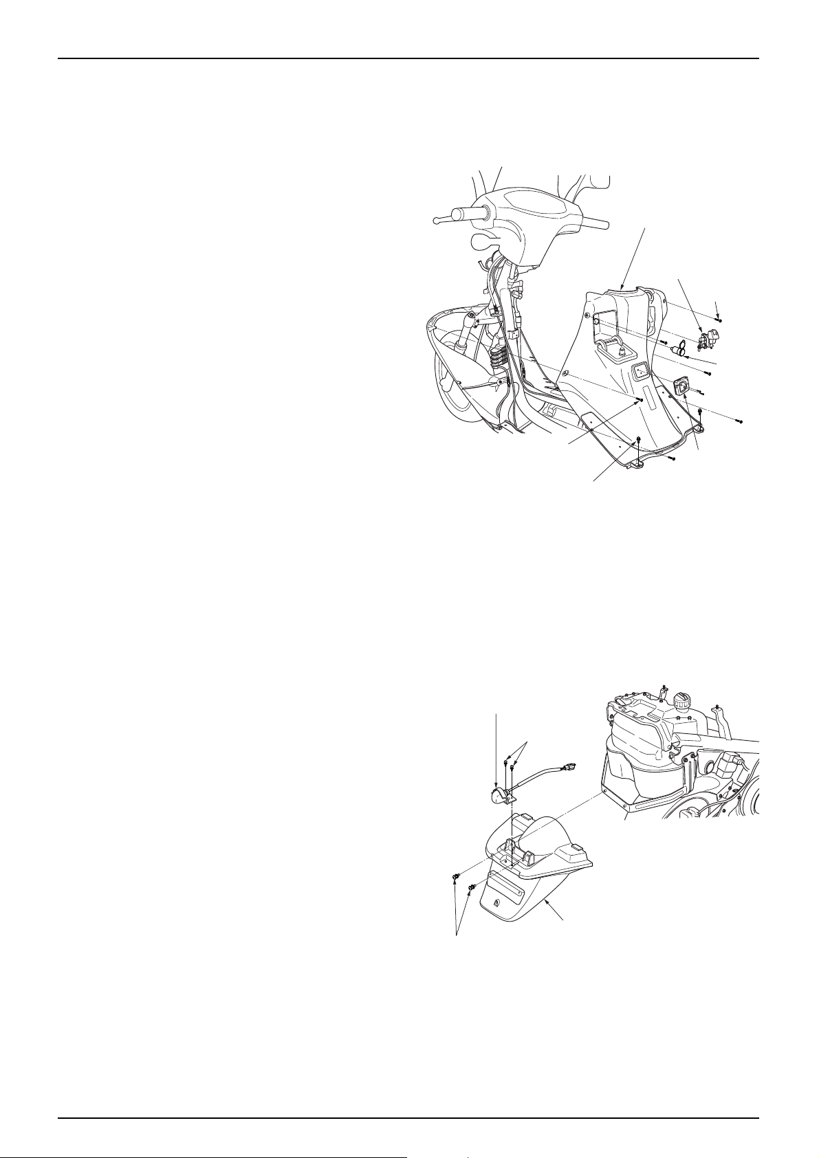
INNER BOX / INNER BOX LID
● Remove the following parts.
-Front cover (⇨4-3)
-Luggage box (⇨4-4)
-Center cover (⇨4-5)
-Rear center cover (⇨4-5)
-Rear carrier and back rest (⇨4-6)
-Body cover (⇨4-6)
-Floor side cover (⇨4-7)
-Floor panel (⇨4-8)
● Loosen the 2 tapping screws securing the front
under cover.
● Loosen the 2 special screws (R/L) securing the rear
part of the front under cover.
● Loosen the 2 pan screws securing the bag holder,
remove the bag holder.
● Turn the main key cover slightly to release the
locking and remove the main key cover.
● Loosen the pan screw securing the parking brake
lever, remove the parking brake grip.
● Disconnect the coupler of the charge socket,
remove the charge socket from the inner box.
● Remove the inner box.
● Loosen the 2 tapping screws, remove the parking
brake lever seal.
● Remove the inner box lid from the inner box.
● Remove the lock key setting spring, and remove the
inner box lid key.
● Install in the reverse order of removal.
REAR FENDER
● Release the seat lock by turning the main switch
key to open the seat.
● Remove the seat.
● Remove the following parts.
-Luggage box (⇨4-4)
-Center cover (⇨4-5)
-Rear center cover (⇨4-5)
-Rear carrier (⇨4-6)
-Back rest (⇨4-6)
-Body cover (⇨4-6)
● Disconnect the license lamp wiring, loosen the
washer screw securing the rear fender, and remove
the license lamp assembly.
● Loosen the 2 washer bolts securing the fuel tank
support stay.
● Remove the rear fender.
● Install in the reverse order of removal.
4-9
INNERBOX
BACKHOLDER
SPECIALSCREW
TAPPINGSCREW
PARKINGBRAKE
PANSCREW
CHARGE
SOCKET
WASHERSCREW
WASHERBOLT
REARFENDER
LICENSELAMPASSEMBLY
EXTERNAL P ARTS
Page 48

WIND SCREEN /
FRONT HANDLE COVER
● Loosen the 3 screen setting screws securing the
front handle cover.
● Pulling the cover to the under slightly and remove
the wind screen from the front handle cover groove.
● Loosen the 4 tapping screws (FR./RR.) securing the
rear handle cover.
● Loosen the front handle cover LH./RH. setting pan
screws (2EA) securing the steering handle.
● Remove the handle cover, disconnect the RH./LH.
winker wiring.
● Remove the 3 wind screen setting nuts securing the
front handle cover.
● Loosen the RH./LH. winker setting hex nuts
securing the front handle cover, remove the
RH./LH. winker.
● Install in the reverse order of removal.
REAR HANDLE COVER
● Remove the front handle cover. (⇨4-10)
● Loosen the 2 tapping screws securing the steering
handle.
● Remove the speedometer cable from the meter.
● Disconnect the stop switch wiring of the RH./LH.
master cylinder assembly .
● Disconnect the winker relay wiring securing the winker
relay .
● Remove the rear handle cover from the steering handle.
● Disconnect the right and left switch wiring, remove the
switches.
● Loosen the 4 speedometer setting tapping screws
securing the rear handle cover .
● Remove the rear handle cover.
● Install in the reverse order of removal.
NOTE
•Check each switch for proper operation after
installation.
•Wires and cables must be connected properly.
4-10
TAPPINGSCREW
TAPPINGSCREW
LH.WINKERASSEMBLY
RH.WINKERASS'Y
FRONT
HANDLECOVER
HEXNUT
SETTINGSCREW
SPEEDOMETERASSEMBLY
TAPPINGSCREW
REARHANDLECOVER
TAPPINGSCREW
TAPPINGSCREW
EXTERNAL P ARTS
Page 49

REAR WHEEL MUD GUARD
● Loosen the washer bolt securing the LH. crankcase.
● Loosen the washer bolt securing the RH. crankcase.
● Loosen the washer bolt securing EX. muffler bracket.
● Remove the rear wheel mud guard.
● Install in the reverse order of removal.
NOTE
•Never perform the maintenance of the muffler right
after stopping the vehicle because the muffler is
extremely hot.
4-11
WASHERBOLT
WASHERBOLT
REARWHEELMUDGUARD
EXTERNAL P ARTS
Page 50

MUFFLER
REMOV AL
● Loosen the 3 cap nuts securing the EX. pipe comp.
● Loosen the flange bolt securing the upper part of
the RH. crankcase cover.
● Loosen the rear brake hose setting bolt.
● Loosen the flange bolt securing the rear wheel mud
guard.
● Loosen the 2 flange bolts securing the lower part of
the rear swing arm.
● Remove the EX. muffler comp.
WARNING
•Never perform the maintenance of the muffler right
after stopping the vehicle because the muffler is
extremely hot.
EX. PIPE REMOV AL
● Remove the plug maintenance cover.
● Loosen the 2 flange bolts securing the cylinder
comp.
● Remove the EX. pipe by drawing it to the ground
direction.
INST ALLATION
● Insert the EX. pipe gasket to the EX. pipe.
● Insert the EX. pipe to the cylinder comp, and
tighten the 2 flange nuts with specified torque.
● Install the plug maintenance cover.
NOTE
•Tighten the flange nuts diagonally and alternately
and tighten with specified torque in the end.
● Insert the flange gasket to the EX. muffler comp.
● Tighten the flange bolt securing the RH. crankcase
cover.
● Tighten the 2 flange bolts securing the swing arm.
TORQUE VALUE :5.5 kgf·m
● Tighten the 3 cap nuts securing the EX. pipe comp.
● Tighten the rear brake hose setting nut.
● Tighten the flange bolt securing the rear wheel mud
guard.
NOTE
•When installing the gasket, replace it with the new
one.
•Check to see if there is any evacuation after
installing the muffler.
4-12
EXTERNAL P ARTS
EX. MUFFLER
FLANGE BOLT
FLANGE BOLT
CAP NUT
EX. PIPE
FLANGE NUT
FLANGE BOLT
EX.MUFFLER
FLANGE NUT
FLANGE BOLT
FLANGE BOLT
CAP NUT
Page 51
MEMO
Page 52
FUEL SYSTEM
5-0
FUELTANK
FUELSTRAINER
FUELPUMP
CARBURETOR
Page 53

SERVICE INFORMATION
GENERAL SAFETY
WARNING
● Gasoline is extremely flammable. Avoid fire in the work place, also paying particular attention to sparks. Furthermore,
the evaporated (gasified) gasoline is highly explosive. Work in a well-ventilated areas.
● Exhaust gas contains poisonous substance. Do not keep engine running for a long period of time in a closed, or poorly
ventilated area.
CAUTION
● Do not excessively bend or twist cable. Distorted or damaged cable may lead to mechanical malfunctions.
● Pay particular attention to the position of O-ring. Replace with new ones when disassembled.
● If it is desired to store a vehicle for a period longer than 1 month, drain gasoline out of the carburetor float chamber.
Gasoline left in the float chamber will be deteriorated causing the slow jet to be clogged with deposits, and idling may
become unstable.
SPECIFICA TIONS
FUEL T ANK CAPACITY : 8ℓ
RESER VE FUEL CAPACITY: 2ℓ
CARBURETOR
TOOL
FLOAT LEVEL GAUGE
5-1
5. FUEL SYSTEM
5
SERVICE INFORMATION
····
5-1
TROUBLESHOOTING
········
5-2
FUEL TANK
················
5-3
ITEM
TYPE/THROTTLE BORE
MODEL MARK
MAIN JET No.
PILOT SCREW OPENING
FLOAT LEVEL
IDLING SPEED
THROTTLE GRIP FREE PLAY
STANDARD
CV TYPE (VACUUM)/24.2mm
BDS26 - 112
#95
1½ RETURNS
13.0mm
1,800±100rpm
2-6mm
AIR CLEANER
··············
5-4
CARBURETOR
··············
5-4
PILOT SCREW ADJUSTMENT··5-10
Page 54

5-2
FUEL SYSTEM
TROUBLESHOOTING
The vehicle does not start.
● No gasoline in fuel tank.
● Fuel is not coming out of carburetor.
● Too much fuel is flowing into cylinder.
● No spark emitted from spark plug.
● Air cleaner is blocked.
● Suction system is experiencing secondary intake of air.
● Using low quality gasoline.
● Starter is damaged.
● Throttle cable is working improperly.
● Fuel tank is functioning improperly.
Idle is unstable and engine turns off after starting.
● Starter is damaged.
● Ignition system is damaged.
● Using low quality gasoline.
● Suction system is experiencing secondary intake of air.
● Idle is adjusted improperly.
● Air screw is adjusted improperly.
● Compression pressure is low.
● Air/Fuel mixture is either too lean or rich.
● Carburetor is blocked.
Mis-firing occurs when driving at high speeds.
● Ignition system is damaged.
● Mixture is too lean.
Back firing
● Ignition system is damaged.
● Mixture is too lean.
Insufficient power and high fuel consumption.
● Air cleaner is blocked.
● Ignition system is damaged.
● Mixture is too rich.
Air/Fuel mixture is extremely lean
● Fuel jet is blocked.
● Float valve is damaged.
● Oil level is low.
● Bad ventilation of air in tank cap.
● Fuel strainer screen is blocked.
● Fuel tube is bent, creased or blocked.
● Suction system is receiving secondary suction of air.
Air/Fuel mixture is extremely rich.
● Air jet is blocked.
● Float valve is damaged.
● Oil level is too high.
● Starter is damaged.
● Air cleaner is blocked.
Page 55

5-3
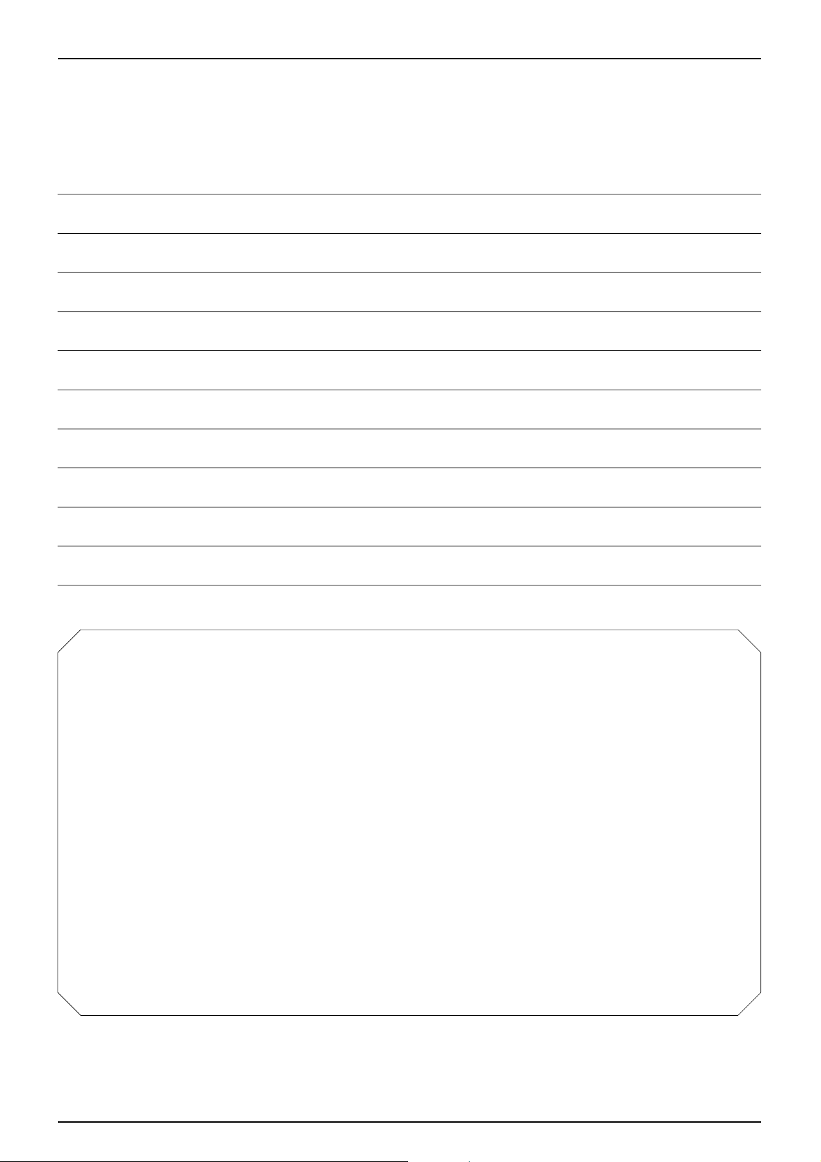
FUEL SYSTEM
FUEL TANK
FUEL TUBE
FUEL PUMP
FUEL TANK
REMOV AL
WARNING
•Gasoline is extremely flammable. Avoid fire during
work, and pay particular attention to electric sparks.
Furthermore, the evaporated (gasified) gasoline is
highly explosive. Work in a well-ventilated areas.
● Release the seat lock by turning the main switch key to
open the seat.
● Remove the following parts.
- Luggage box. (⇨4-4)
- Plug maintenance cover.(⇨4-5 )
- Center cover. (⇨4-5)
- Rear center cover. (⇨4-5)
- Rear carrier/Back rest. (⇨4-6)
- Body cover. (⇨4-6)
● Remove the fuel tube from the fuel tank.
NOTE
•Use the tube clip or the cap to prevent the gasoline
from leaking.
● Remove the fuel unit wire coupler.
● Remove the license lamp wire coupler.
● Loosen the 4 flange bolts securing the fuel tank support
stay, remove the fuel tank with the fuel tank support
stay and rear fender from the frame.
● Loosen the 2 flange bolts securing the fuel tank,
remove the fuel tank by drawing down it slightly.
NOTE
•After removing the fuel tank, be sure to close the fuel
tank cap.
INST ALLATION
● Install in the reverse order of removal.
NOTE
• Check for gasoline leakage.
•“Gasoline”mark is on the fuel tank cap.
• Check this mark when filling gasoline.
FUEL UNIT
COUPLER
FLANGE BOLT
FLANGE
BOLT
FUEL TANK CAP
Page 56
5-4
FUEL SYSTEM
FLANGE BOLT
COUPLING
BAND A
INTAKE
COUPLING
COUPLING
BAND B
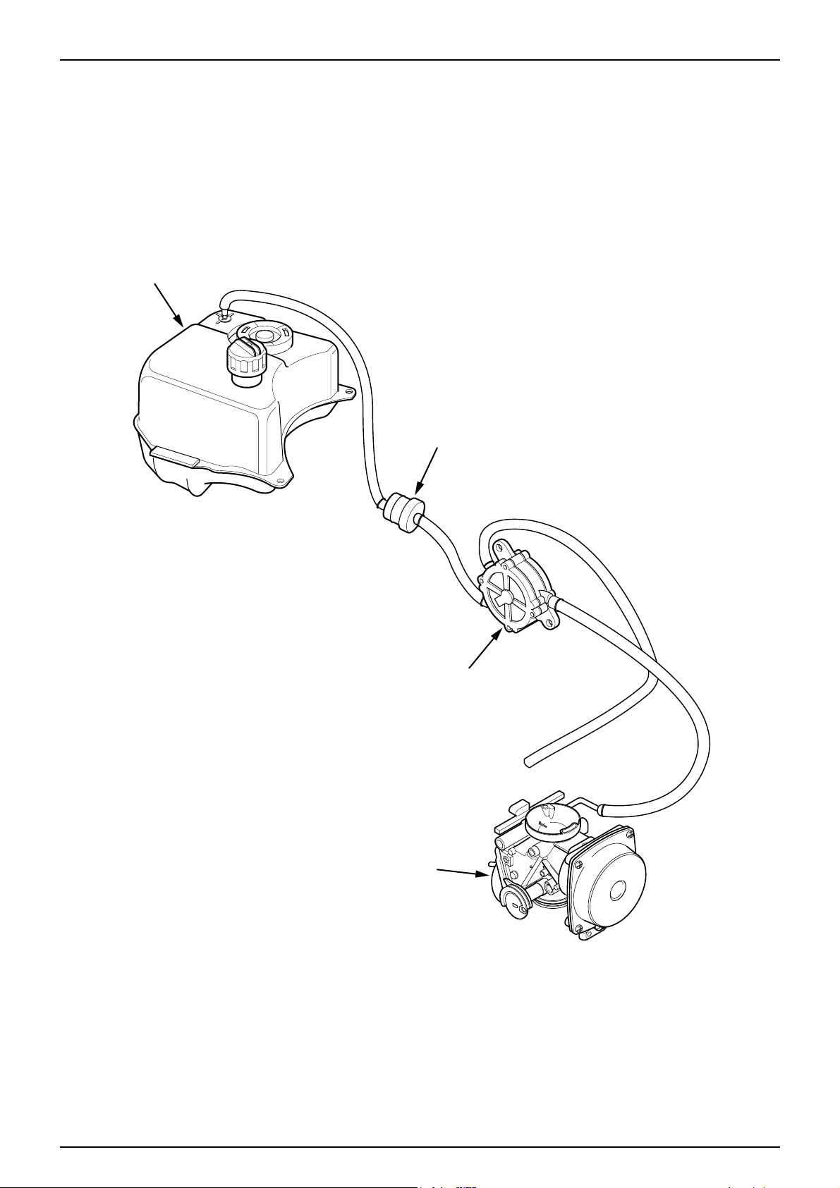
AIR CLEANER
DUCT CLIP
INLET DUCT
AIR CLEANER
REMOV AL
● Remove the luggage box. (⇨4-4)
● Remove the center cover. (⇨4-5)
● Loosen the intake coupling band B securing the
carburetor, remove the air cleaner from the carburetor.
● Remove the air band hose securing the air cleaner.
● After pressing the duct clip securing the air cleaner,
remove the air cleaner inlet duct.
● Loosen the 3 flange bolts (left 1, right 2) securing the
frame body .
● Remove the air cleaner.
● Install in the reverse order of removal.
CARBURETOR
REMOVAL
● Remove the luggage box. (⇨4-4)
● Remove the center cover. (⇨4-5)
● Remove the air cleaner. (⇨5-4)
● Loosen the throttle cable lock nut, and remove the
throttle cable from the carburetor .
● Remove the fuel tube from the carburetor.
● Remove the wiring coupler of the auto bystarter.
● Loosen the set plate setting screw.
● Loosen the screw of the carburetor insulator band 46.
● Remove the carburetor.
AIR CLEANER
FLANGE BOLT
CARBURETOR
THROTTLE CABLE
AUTO BYSTARTER
WIRING
SETTING SCREW
INSULATOR BAND 46
Page 57

5-5
FUEL SYSTEM
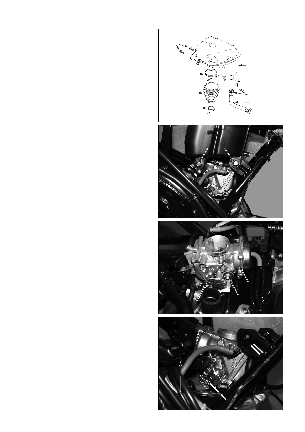
CARBURETOR DISASSEMBLY
● Remove the drain tube and air band hose.
● Loosen the 4 diaphragm cover setting screws.
● Remove the diaphragm cover.
● Remove the diaphragm spring, diaphragm assembly.
● Turn the jet needle with a ⊖ screwdriver, and remove
the needle spring, spring holder, and jet needle from the
vacuum piston.
CARBURETOR INSPECTION
● Check the jet needle for stepped wear and replace if
necessary .
● Check the vacuum piston for damage and replace if
necessary .
● Check the diaphragm for damage, pin holes, wrinkles
and bends and replace if necessary .
NOTE
•Air leaks out of the vacuum chamber if the
diaphragm is damaged in any way-even a pin hole.
DRAIN TUBE
DIAPHRAGM COVER
SCREW
AIR BAND HOSE
DIAPHRAGM
DIAPHRAGM SPRING
NEEDLE SCREW
SPRING HOLDER
JET NEEDLE
HOLDER
DIAPHRAGM
JET NEEDLE
SPRING
Page 58

5-6
FUEL SYSTEM
FLOAT CHAMBER/FLOAT/JET
DISASSEMBLY
● Loosen the 4 screws securing the float body.
● Remove the float pin, float, and float value.
● Check the float valve and valve seat for scores, scratches,
clogging and damage. Replace if necessary .
● Check the float valve operation.
● Remove the main jet, main jet holder, holder washer,
jet screw, jet washer, needle jet, slow jet, pilot jet,
washer and O-ring.
NOTE
•Turn in the pilot jet and record the number of turns it
takes before it seats lightly .
•Do not force the pilot screw against its seat ;
the seat will be damaged.
FLOAT BODY ASS'Y
SCREW
SCREW
FLOAT VALVE
PIN
FLOAT
FLOAT VALVE
SLOW JET
SEAT
MAIN JET
HOLDER
MAIN JET
Page 59

5-7
FUEL SYSTEM
CARBURETOR BODY
CARBURETOR CLEANING
● After removing all parts, blow open air and fuel
passages in the carburetor body with compressed air .
CAUTION
•Cleaning the air and fuel passages with a piece of
wire will damage the carburetor body or fuel pump.
FLOAT CHAMBER/FLOAT/JET
ASSEMBLY
● Install the needle jet, needle jet holder, main jet and
slow jet.
● Tighten the pilot jet until it seats lightly, then turn it
out as much as the number recorded during removal.
● Install the pilot jet rubber.
MAIN JET
NEEDLE JET
FLOAT BODY
SLOW JET
FLOAT
PLUNGER ASS'Y
DIAPHRAGM
JET NEEDLE
SPRING
DIAPHRAGM COVER
PILOT JET
FLOAT VALVE
PILOT JET
Page 60
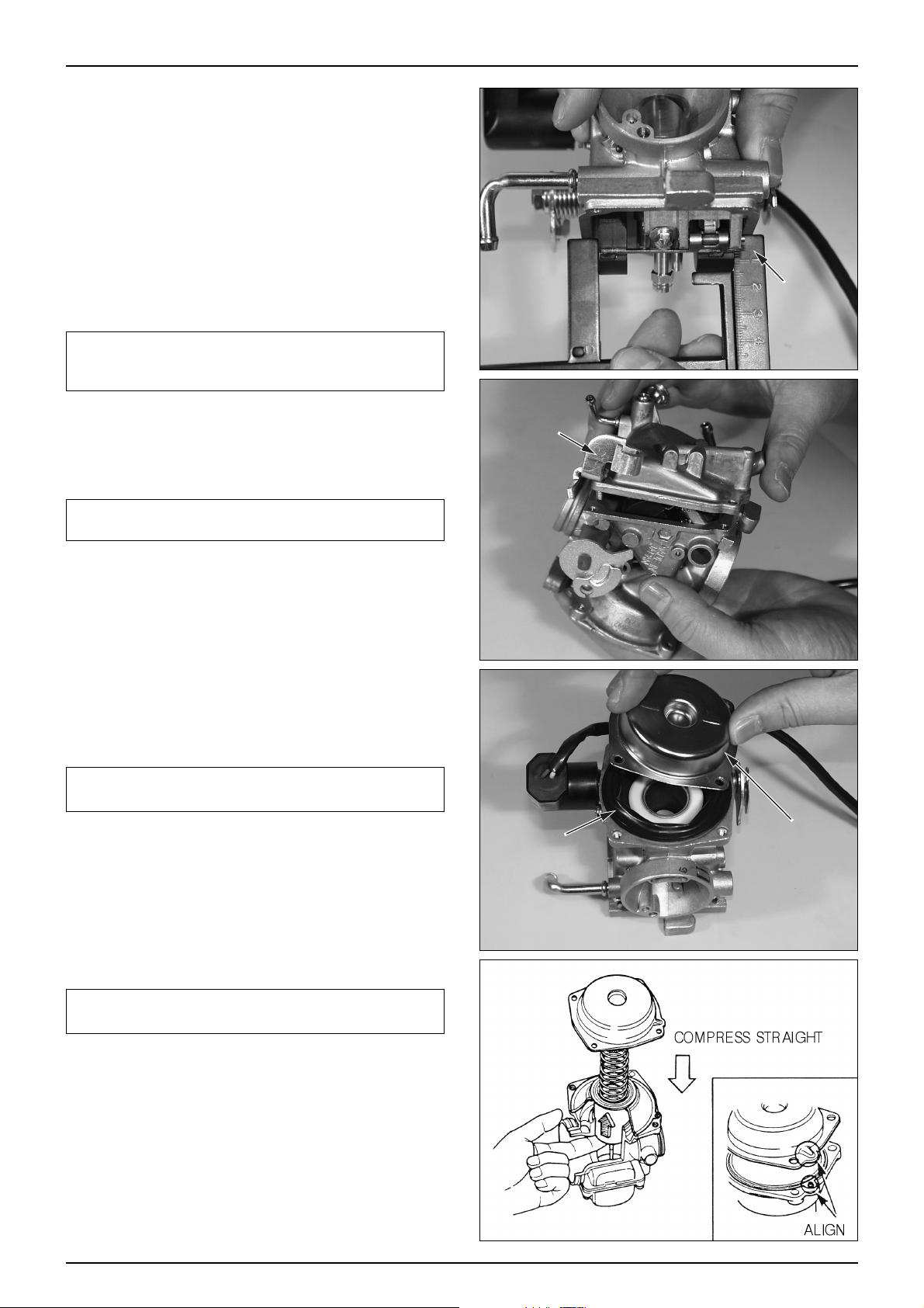
5-8
FUEL SYSTEM
FLOA T LEVEL INSPECTION
● Install the float valve, float, float pin.
● Measure the float level with the float level gauge.
FLOAT LEVEL : 13 mm
TOOL : FLOAT LEVEL GAUGE
● If the level is out of specification and the float arm lip
can be bent, adjust the float level by bending the lip.
Non-adjustable floats must be replaced.
NOTE
•Be sure to keep the float level at the specified height.
If the float level is low / high, fuel mixture becomes
lean / rich.
● Install the float body assembly, install the bracket and 4
pan screws.
NOTE
•Be sure to replace the float chamber body O-ring
with the new one.
● Insert the jet needle, needle spring holder, needle
spring, diaphragm assembly, and install the needle
screw .
NOTE
•Install the jet needle aligned with the grooves in the
diaphragm.
● Install the diaphragm assembly on the carburetor body.
● Install the diaphragm spring.
● Install the diaphragm cover with its cutout aligned with
the hole in the tab of diaphragm.
NOTE
•Be careful not to pinch the diaphragm, and to keep
the spring straight.
● Install the auto bystarter wiring plate to the diaphragm,
and tighten the 4 pan screws.
● Install the drain tube and air-hose.
FLOAT
LEVEL
GAUGE
FLOAT BODY
DIAPHRAGM
DIAPHRAGM
COVER
Page 61
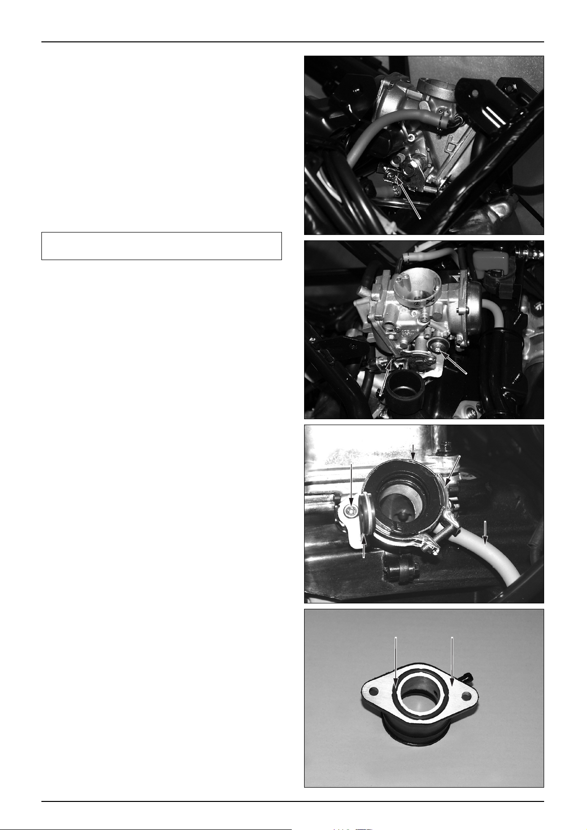
5-9
FUEL SYSTEM
CABURETOR INSTALLA TION
● Install the carburetor to the carburetor insulator.
● Tighten the carburetor insulator band screw .
● Tighten the setting screw securing the carburetor and
set plate.
● Install the fuel tube to the carburetor.
● Install the wiring coupler of the auto bystarter.
● Install the throttle cable to the carburetor.
● Install the air cleaner.(⇨5-4)
● Install the center cover.(⇨4-5)
● Install the luggage box.(⇨4-4)
NOTE
•After adjusting the carburetor, check the throttle grip
free play .
CABURETOR INSULATOR
REMOV AL
● Remove the luggage box. (⇨4-4)
● Remove the center cover. (⇨4-5)
● Remove the air cleaner. (⇨5-4)
● Remove the carburetor. (⇨5-4)
● Remove the fuel pump negative pressure tube.
● Loosen the carburetor insulator RH. socket bolt, and
remove the carburetor setting plate and socket bolt.
● Loosen the carburetor insulator LH. socket bolt, and
remove the carburetor insulator .
● Remove the carburetor insulator band.
● Install in the reverse order of removal.
INSPECTION
● Check the carburetor insulator O-ring for wear or
damage.
THROTTLE CABLE
INSULATOR
SOCKET BOLT
SETTING PLATE
INSULATOR BAND
SETTING SCREW
INSULATOR BAND
NEGATIVE
PRESSURE TUBE
O-RING INSULATOR
Page 62

PILOT SCREW ADJUSTMENT
● Remove the luggage box. (⇨4-4)
● Remove the pilot jet rubber.
● Remove the plug maintenance cover. (⇨4-5)
① Turn the pilot screw clockwise until it seats lightly, then
back it out to the specification given (1½).
② Warm up the engine to operating temperature (60℃).
③ Adjust the idle speed with the throttle stop screw.
IDLE SPEED : 1,800 ±100 rpm
NOTE
•The pilot screw is factory pre-set. Adjustment is not
necessary unless the caburetor is overhauled or a new
pilot screw is installed.
•Before adjusting the pilot screw, check the following
items.
-Fuel system, electrical system for troubling.
-Spark plug for cleaning and gap adjusting.
-Valve clearance for adjusting.
CAUTION
•Tightening the pilot screw against its seat will
damage the seat.
④ Rev the engine up slightly from the idle speed and
make sure that engine speed rises and returns smoothly.
⑤ When turning the throttle stop screw in gradually until
the engine speed drops 1,000rpm, make sure that the
engine does not run.
Adjust by turning the pilot screw with a ⅛ turn and
repeat steps ④ and ⑤
CAUTION
•If the engine cannot be adjusted by turning the pilot
screw within a ¼ turn, check for other engine
problems.
⑥ Readjust the idle speed with the throttle stop screw.
● Install the plug maintenance cover. (⇨4-5)
● Install the pilot jet rubber.
● Install the luggage box. (⇨4-4)
5-10
FUEL SYSTEM
THROTTLE
STOP SCREW
PILOT SCREW
ADJUSTMENT
THROTTLE
STOP SCREW
PILOT SCREW
ADJUSTMENT
Page 63

6-1
6. ENGINE REMOVAL
SERVICE INFORMATION
GENERAL SAFETY
NOTE
•Use a jack to remove or install the engine. Support the motorcycle with a jack firmly, taking precautions not to
damage the frame, engine, cable or harness.
•Attach tape to the frame to protect it during the engine removal or installation.
● The following works can be carried out without removing the engine from the vehicle body .
-TRANSMISSION (⇨SECTION 11)
-ST ARTING CLUTCH (⇨SECTION 8)
-OIL PUMP (⇨SECTION 2)
-A.C. GENERATOR (⇨SECTION 8)
-ST ARTER MOTOR (⇨SECTION 17)
-KICK ST ARTER/ CONTINUOUSLY VARIABLE TRANSMISSION (⇨SECTION 7)
-CYLINDER HEAD/ CYLINDER/ PISTON (⇨SECTION 9,10)
-EX. MUFFLER (⇨SECTION 4)
-CARBURETOR (⇨SECTION 5)
-REAR SWING ARM (⇨SECTION 13)
● Items to be worked after removing engine.
-CRANKSHAFT , CRANKSHAFT BEARING, CRANK CASE BEARING
● Engine oil capacity : 1.1ℓ- when disassembled.
TORQUE VALUES :
ENGINE HANGER BOLT (FRONT) : 2.7㎏f·m
(REAR) : 3.5㎏f·m
6
SERVICE INFORMATION
··········
6-1
ENGINE REMOVAL
················
6-2
Page 64

6-2
ENGINE REMOV AL
ENGINE REMOVAL
● Drain the engine oil.
● Release the seat lock by turning the main switch key to
open the seat.
● Remove the following parts.
-Luggage box (⇨4-4)
-Center cover (⇨4-5)
-Air cleaner (⇨5-4)
-Carburetor (⇨5-4)
● Disconnect the A.C generator coupler and connector
wiring connected to the A.C generator, disconnect the
starter motor wiring cable.
●Remove the battery earth cable from the RH. shroud
groove.
● Disconnect the high-tension cord from the engine.
● Remove the bleeder tube from the cylinder head cover.
● Loosen the parking brake rod adjuster nut B, remove
the parking brake cable.
● Remove the negative pressure tube from the carburetor
insulator.
● Remove the EX. muffler. (⇨4-12)
● Remove the rear brake caliper. (⇨14-6)
● Remove the RH./LH. floor side cover. (⇨4-7)
● Remove the under cover (⇨4-8)
BATTERY
EARTH CABLE
ACG WIRING
COUPLER
STARTER
MOTOR CABLE
ADJUSTER NUT B
REAR BRAKE CALIPER
UNDER COVER
Page 65

6-3
ENGINE REMOV AL
● Remove the RH./LH. radiator hose, remove the
RH./LH. radiator hose from the frame setting clamp.
● Loosen the U-nut securing the engine hanger.
● Loosen the rear cushion lower bolt.
● Remove the engine. (with the rear swing arm and rear
wheel attached)
● Remove the rear swing arm. (⇨13-8)
● Remove the rear wheel. (⇨13-3)
● Remove the rear wheel mud guard. (⇨4-11)
ENGINE INST ALLATION
● Install in the reverse order of removal.
NOTE
•Take precautions not to damage wiring and cable.
•Take precautions not to damage the threaded part of
bolts.
•Arrange the cable, tubes and wiring in the right
positions.
TORQUE VALUE
ENGINE HANGER BOLT (FRONT) : 4.5㎏f·m
(REAR) : 4.5㎏f·m
● Check the following after the engine is installed.
-Engine oil
-Electric systems.
-Adjust of the parking brake free play .
-Inspection of the throttle cable operation.
RADIATOR HOSE
U-NUT
LOWER BOLT
Page 66

7-0
LH. CRANKCASE COVER/KICK ST ARTER/CONTINUOUSL Y VARIABLE TRANSMISSION
LH. CRANKCASE COVER
Page 67
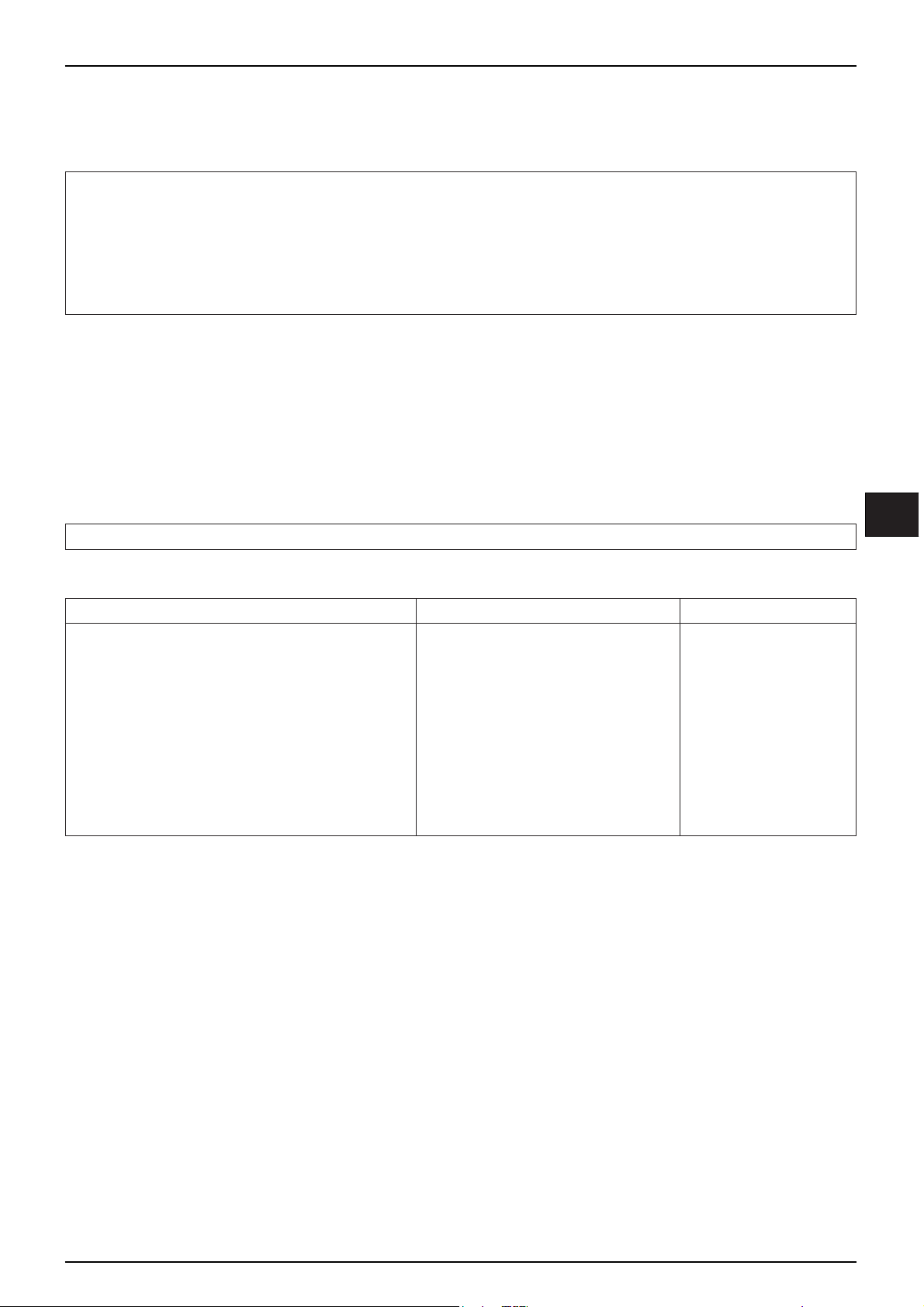
7-1
7. LH. CRANKCASE COVER/KICK STARTER
/CONTINUOUSLY VARIABLE TRANSMISSION
SERVICE INFORMATION
GENERAL SAFETY
● Do not allow oil to contact the drive belt or the pulley face. The transmission rate of driving force is reduced with oil
contact.
● Do not operate starter motor while the LH. crank case cover is removed.
NOTE
·Take precautions not to apply the grease oil to the movable drive face or weight roller.
SPECIFICA TIONS
7
SERVICE INFORMATION
······
7-1
TROUBLESHOOTING
········
7-1
LH. CRANKCASE COVER
····
7-2
KICK STARTER
··············
7-3
ITEM STANDARD SERVICE LIMIT
MOVABLE DRIVE F ACE BUSHING INNER DIAMETER
24.000-24.013mm 24.05mm
DRIVE F ACE BOSS OUTER DIAMETER
23.980-23.993mm 23.96mm
DRIVE BELT WIDTH 22mm 20.50mm
WEIGHT ROLLER OUTER DIAMETER
19.95-20.02mm 19.50mm
CLUTCH OUTER INNER DIAMETER
120.0-120.2mm 120.50mm
DRIVEN F ACE SPRING PLAY 97.85mm 90.00mm
DRIVEN F ACE OUTER DIAMETER 37.965-37.985mm 37.94mm
DRIVEN F ACE INNER DIAMETER 38.000-38.025mm 38.06mm
TROUBLESHOOTING
Engine starts but motorcycle does not work.
● Drive belt worn.
● Ramp plate damaged.
● Clutch shoe worn or damaged.
● Movable driven face spring cut.
Engine stops, or the vehicle runs suddenly ,
after starting.
● Clutch shoe spring cut.
Vehicle unable to run at the maximum speed,
or lack of output
● Drive belt worn.
● Defective movable driven face spring.
● Weight roller worn.
● Pulley face contaminated.
DRIVE BELT
················
7-6
MOVABLE DRIVE FACE
······
7-8
CLUTCH/DRIVEN PULLEY
····
7-11
Page 68

LH. CRANKCASE COVER
REMOV AL
● Remove the 12 flange bolts securing LH. crankcase.
● Remove the LH. crankcase cover.
● Remove the gasket and dowel pin.
INST ALLATION
● Install the new gasket and dowel pin after removing the
gasket of the crankcase surface.
NOTE
·Align the bolts to uniform the tightening location
before tightening then when you don’t know the bolt
length.
·Tighten the bolts diagonally with specified tightening
torque.
·Be sure to replace a new gasket and dowel pin
● Tighten the LH. crankcase cover bolts.
7-2
LH. CRANKCASE COVER/KICK ST ARTER/CONTINUOUSL Y VARIABLE TRANSMISSION
KICK STARTER
LH. CRANKCASE COVER
PEDAL
DOWEL PIN
DOWEL PIN
GASKET
LH. CRANKCASE COVER
Page 69
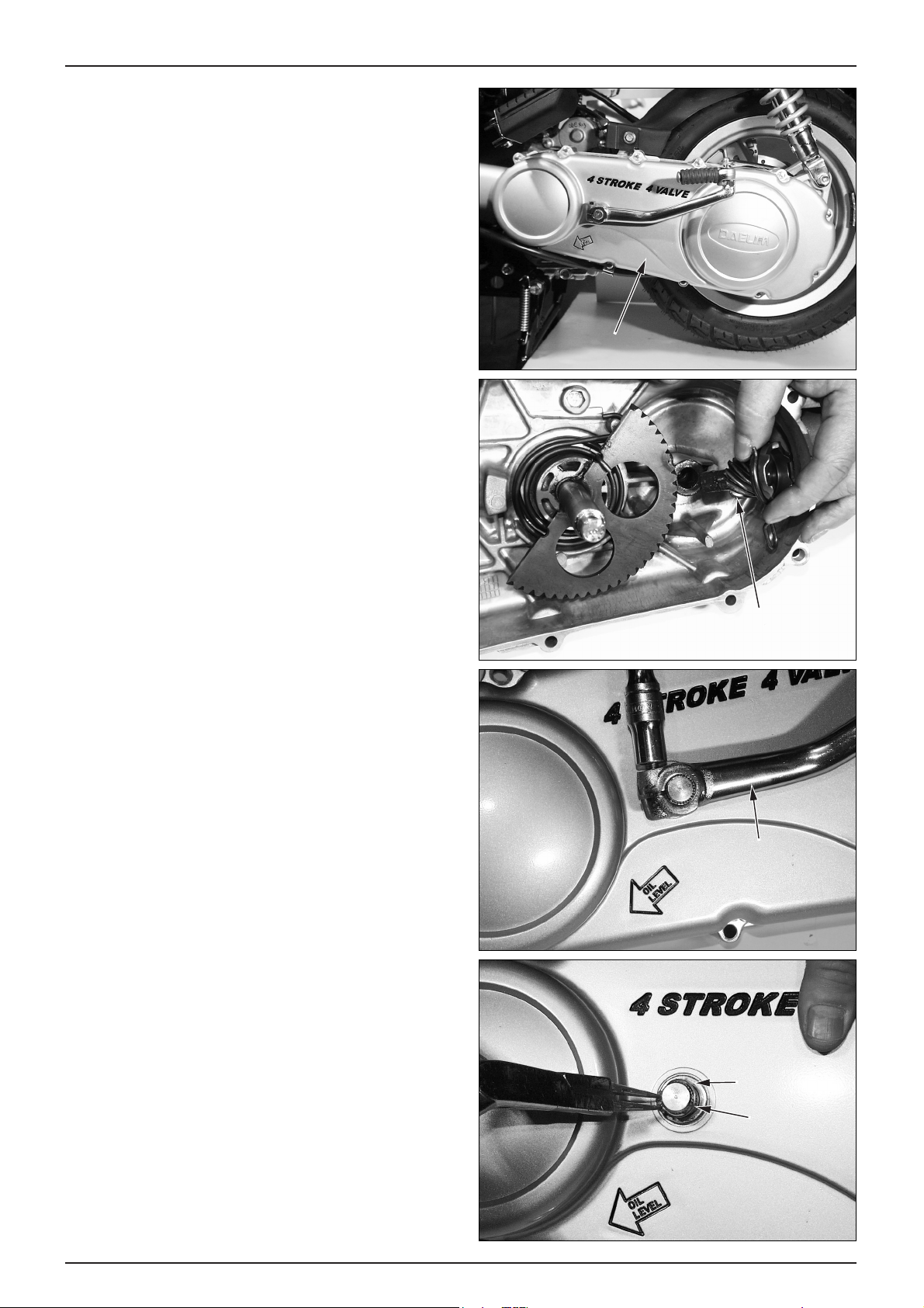
KICK STARTER
REMOV AL
● Remove the LH. crankcase cover. (⇨7-2 )
● Rotate the kick starter spindle using the kick starter
pedal, remove the kick driven gear and 13mm thrust
washer.
● Loosen the kick starter pedal bolt.
● Remove the kick starter pedal.
● Remove the 14mm external circlip.
● Remove the kick spindle washer.
7-3
LH. CRANKCASE COVER/KICK ST ARTER/CONTINUOUSL Y VARIABLE TRANSMISSION
LH. CRANKCASE COVER
KICK DRIVEN
GEAR SET
KICK STARTER
PEDAL
KICK SPINDLE
WASHER
CIRCLIP
Page 70

● After removing the kick starter spindle from the return
spring, remove the kick starter spindle from the LH.
crankcase cover .
● Remove the kick starter return spring, kick starter bush
from the LH. crankcase cover .
KICK ST ARTER
INSPECTION
● Check the kick starter spindle for wear or damage.
● Check the return spring for defects or damage.
● Check the kick starter bush for damage.
● Check the kick starter driven gear for wear and damage.
● Check the friction spring for defects and damage.
7-4
LH. CRANKCASE COVER/KICK ST ARTER/CONTINUOUSL Y VARIABLE TRANSMISSION
KICK STARTER SPINDLE
KICK STARTER BUSH
KICK STARTER RETURN SPRING
KICK STARTER RETURN SPRING
KICK STARTER
SPINDLE
FRICTION SPRING
KICK STARTER
BUSH
KICK STARTER DRIVEN GEAR
Page 71
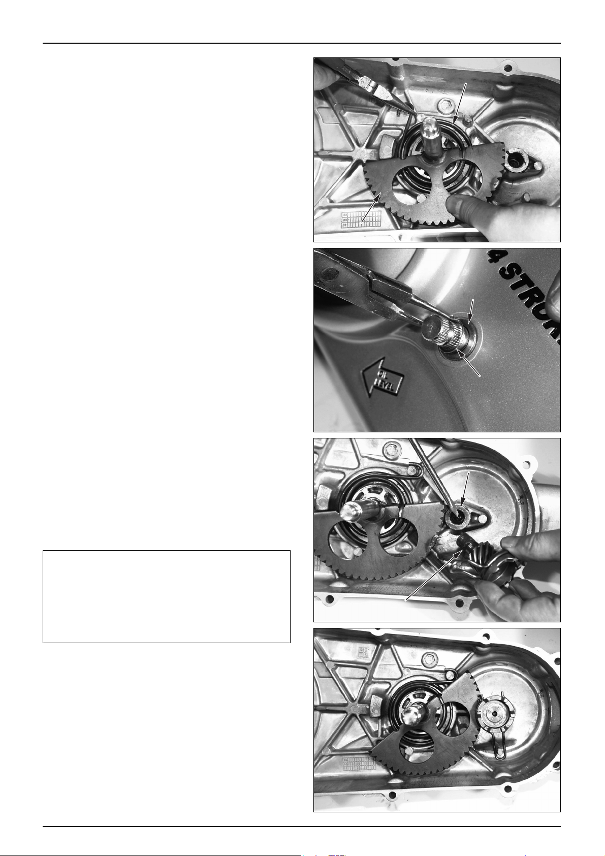
KICK ST ARTER INSTALLATION
● Install the kick spindle bush, spring in the LH.
crankcase cover .
● Install the kick starter spindle, then install the return
spring to the kick starter spindle.
● Install the kick starter spindle washer and 14mm
external cir-clip.
● Install the kick starter pedal to the spindle, and tighten
the flange bolt.
● Rotate the kick starter spindle using the kick starter
pedal, install the kick driven gear and 13mm thrust
washer.
● Install the LH. crankcase cover. (⇨7-2 )
NOTE
·When installing the 14mm external circlip, keep
holding the spindle manually and install the
circlip in the groove correctly.
·Apply the grease to the kick driven gear groove
and gear.
·Check the kick driven gear and the kick starter
spindle for smooth operation after installation.
7-5
LH. CRANKCASE COVER/KICK ST ARTER/CONTINUOUSL Y VARIABLE TRANSMISSION
KICK STARTER
RETURN SPRING
KICK STARTER SPINDLE
WASHER
CIRCLIP
THRUST WASHER
KICK DRIVEN GEAR
Page 72

DRIVE BELT
REMOV AL
● Remove the LH. crankcase cover. (⇨7-2 )
● Hold the clutch outer using the universal holder and
remove the nut.
● Remove the clutch outer.
TOOL: UNIVERSAL HOLDER
CAUTION
·Use the special tool when loosening the lock nut.
Holding the rear wheel or rear brake will damage the
final reduction system.
● Squeeze the drive belt into the pulley groove as shown
so that it slackens enough to remove the driven pulley
from the drive shaft.
● Loosen the drive face setting nut 12mm with the clutch
center holder.
● Remove the kick starter ratchet and drive face.
TOOL : DRIVE FACE HOLDER
● Remove the driven pulley sub assembly with the drive
belt in place.
● Remove the drive belt from the driven pulley groove
and drive pulley groove.
7-6
LH. CRANKCASE COVER/KICK ST ARTER/CONTINUOUSL Y VARIABLE TRANSMISSION
UNIVERSAL
HOLDER
DRIVE BELT
DRIVEN PULLEY SUB ASS'Y
DRIVE FACE
HOLDER
DRIVEN PULLEY SUB ASS'Y
Page 73

DRIVE BEL T INSPECTION
● Check the drive belt for cracks, pry separation and
wear; replace as necessary .
● Measure the width of the drive belt as shown.
● Replace the belt if the service limit is exceeded.
SERVICE LIMIT : 20.5mm
NOTE
·Use only a genuine DAELIM replacement drive belt.
·Do not get oil or grease on the drive belt or pulley
faces. Clean off any grease or oil before reinstalling.
DRIVE BEL T INSTALLATION
● Temporarily install the driven pulley sub assembly on
the drive shaft.
● Turn the pulley clockwise and spread the faces apart
while installing the drive belt.
● Remove the pulley assembly once with the drive belt
installed.
● Put the drive belt over the movable drive face.
● Install the drive face to the LH. crank shaft, and install
the kick starter ratchet.
● Hold the drive face using the drive face holder and
tighten the nut to the specified torque.
TORQUE VALUE : 7.0-8.0 kgf·m
TOOL : DRIVE FACE HOLDER
NOTE
·Hold the faces apart preventing them from closing.
7-7
LH. CRANKCASE COVER/KICK ST ARTER/CONTINUOUSL Y VARIABLE TRANSMISSION
DRIVEN PULLEY
SUB ASS'Y
MOVABLE DRIVE FACE
DRIVE BELT
Page 74

● Reinstall the driven pulley on the drive shaft with the
drive belt attached.
● Hold the clutch outer using the universal holder.
Tighten the nut to the specified torque.
TORQUE VALUE : 5.0-6.0 kgf·m
TOOL : UNIVERSAL HOLDER
● Reinstall the LH. crankcase cover. (
)Xh
@)X?g
@V/Xg
@?V/X?f
@@@@@@@@@@@??V/Xf
@?hfV/X?e
@?hf?V/Xe
@? N1e
@? J5e
@?hf?W.Ye
@@@@@@@@@@@?eW.Y?e
@??W.Yf
@?W.Y?f
@W.Yg
@(Y?g
(Yh
7-2 )
MOVABLE DRIVE F ACE
REMOV AL
● Remove the LH. crankcase cover. (
)Xh
@)X?g
@V/Xg
@?V/X?f
@@@@@@@@@@@??V/Xf
@?hfV/X?e
@?hf?V/Xe
@? N1e
@? J5e
@?hf?W.Ye
@@@@@@@@@@@?eW.Y?e
@??W.Yf
@?W.Y?f
@W.Yg
@(Y?g
(Yh
7-2 )
● Hold the drive face using the drive face holder and
remove the nut.
TOOL : DRIVE FACE HOLDER
● Remove the kick starter ratchet and drive face.
● If the drive face holder cannot be used, remove the
cooling fan at the right side of the crankshaft, and hold
the flywheel with the universal holder .
TOOL : UNIVERSAL HOLDER
● Remove the drive belt. (
)Xh
@)X?g
@V/Xg
@?V/X?f
@@@@@@@@@@@??V/Xf
@?hfV/X?e
@?hf?V/Xe
@? N1e
@? J5e
@?hf?W.Ye
@@@@@@@@@@@?eW.Y?e
@??W.Yf
@?W.Y?f
@W.Yg
@(Y?g
(Yh
7-6 )
● Remove the movable drive face and drive face boss.
● Remove the ramp plate, weight rollers and oil seal
from the movable drive face.
7-8
LH. CRANKCASE COVER/KICK ST ARTER/CONTINUOUSL Y VARIABLE TRANSMISSION
DRIVE FACE
KICK STARTER RATCHET
DRIVE FACE HOLDER
FACE BOSS
MOVABLE DRIVE FACE
SLIDE PIECE
DRIVE FACE
BOSS
RAMP PLATE
MOVABLE DRIVE
FACE COMP
WEIGHT
ROLLER
Page 75

MOV ABLE DRIVE FACE INSPECTION
● The weight rollers push on the movable drive face (by
centrifugal force); worn or damaged weight rollers will
interfere with this force.
● Check the rollers for wear or damage and replace as
necessary .
● Measure the O.D. of each roller, replace if the service
limit is exceeded.
SERVICE LIMIT : 19.5mm
● Check the drive face boss for wear or damage and
replace as necessary .
● Measure the O.D of the drive face boss. Replace the
boss if the service limit is exceeded.
● Measure the I.D. of the drive face. Replace it if the
service limit is exceeded.
● Movable drive face boss outer diameter.
SERVICE LIMIT : 23.960mm
● Movable drive face inner diameter.
SERVICE LIMIT : 24.025mm
MOV ABLE DRIVE FACE INSTALLA TION
● Install the weight roller on the movable drive face.
● Install the ramp plate.
● Apply the inside of the movable drive face with the
specified amount of grease.
SPECIFIED GREASE : ALVANIA EP2
GREASE APPLICATION : 0.5-1.5 g
● Install the movable drive face boss.
NOTE
·Do not get the grease on the drive face. Remove any
misplaced grease with a degreasing agent.
·Use only the specified grease in the specified amount.
7-9
LH. CRANKCASE COVER/KICK ST ARTER/CONTINUOUSL Y VARIABLE TRANSMISSION
WEIGHTROLLER
MOVABLEDRIVEFACE
BOSS
RAMP PLATE
WEIGHT ROLLER
MOVABLE DRIVE FACE
Page 76

● Install the movable drive face on the crank shaft.
● Squeeze the drive belt into the drive face groove and
pull the drive belt over the drive face shaft.
● Install the drive face and kick starter ratchet, temporarily
tighten the drive face nut.
● Hold the drive face using the drive face holder and
tighten the nut to the specified torque.
TORQUE VALUE : 7.0-8.0 kgf·m
TOOL : DRIVE FACE HOLDER
NOTE
·Tighten the drive face nut to the specified torque.
·Correctly match the drive face and crank shaft
serration when assembling.
·If the drive face holder cannot be used, remove the
cooling fan and hold the flywheel with the universal
holder.
● Install the LH. crankcase cover. (
)Xh
@)X?g
@V/Xg
@?V/X?f
@@@@@@@@@@@??V/Xf
@?hfV/X?e
@?hf?V/Xe
@? N1e
@? J5e
@?hf?W.Ye
@@@@@@@@@@@?eW.Y?e
@??W.Yf
@?W.Y?f
@W.Yg
@(Y?g
(Yh
7-2 )
7-10
LH. CRANKCASE COVER/KICK ST ARTER/CONTINUOUSL Y VARIABLE TRANSMISSION
BOSS
MOVABLE DRIVE FACE
DRIVE BELT
KICK STARTER RATCHET
DRIVE FACE
DRIVE FACE HOLDER
Page 77

CLUTCH/DRIVEN PULLEY
REMOV AL
● Remove the LH. crankcase cover. (
)Xh
@)X?g
@V/Xg
@?V/X?f
@@@@@@@@@@@??V/Xf
@?hfV/X?e
@?hf?V/Xe
@? N1e
@? J5e
@?hf?W.Ye
@@@@@@@@@@@?eW.Y?e
@??W.Yf
@?W.Y?f
@W.Yg
@(Y?g
(Yh
7-2)
● Remove the drive face. (
)Xh
@)X?g
@V/Xg
@?V/X?f
@@@@@@@@@@@??V/Xf
@?hfV/X?e
@?hf?V/Xe
@? N1e
@? J5e
@?hf?W.Ye
@@@@@@@@@@@?eW.Y?e
@??W.Yf
@?W.Y?f
@W.Yg
@(Y?g
(Yh
7-8)
● Hold the clutch outer using the universal holder and
remove the flange nut, then remove the clutch outer .
TOOLS : UNIVERSAL HOLDER
DRIVE FACE HOLDER
● Remove the driven pulley sub assembly from the drive
shaft.
● Remove the drive belt.
DISASSEMBLY
● Install a clutch spring compressor on the pulley
assembly and tighten the tool to gain access to the nut.
NOTE
·Do not overtighten the compressor.
● Hold the clutch spring compressor in a vise as shown
and remove the lock nut using the lock nut wrench.
● Loosen the clutch spring compressor and disassembly
the clutch and spring from the driven pulley .
TOOLS : CLUTCH SPRING COMPRESSOR
LOCK NUT WRENCH
● Remove the drive plate, driven face spring and driven
face spring guide.
7-11
LH. CRANKCASE COVER/KICK ST ARTER/CONTINUOUSL Y VARIABLE TRANSMISSION
DRIVEN
PULLEY ASS'Y
UNIVERSAL
HOLDER
DRIVE BELT
DRIVEN FACE SPRING
SPRING GUIDE
DRIVE PLATE
Page 78
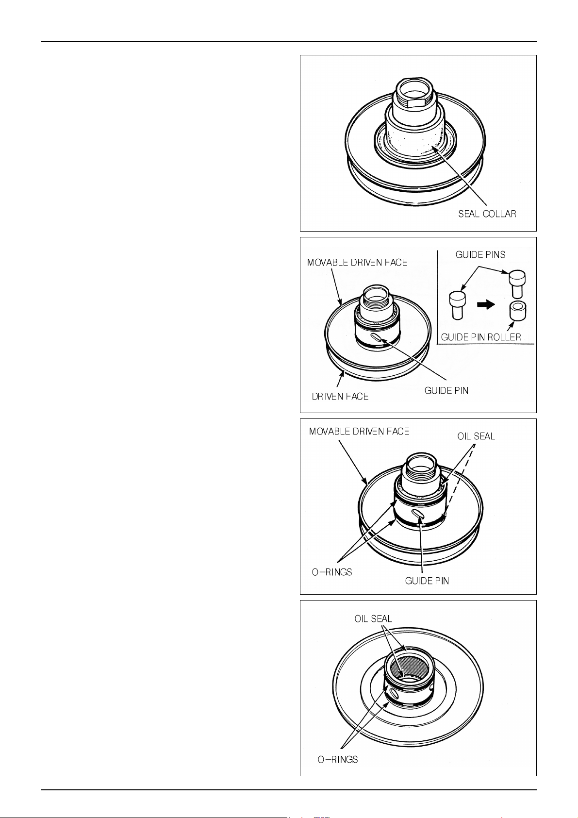
● Remove the seal collar from the driven pulley.
● Remove the guide pins and guide pin rollers and the
movable driven face.
● Remove the O-ring and oil seals from the movable
driven face
● Remove the movable driven face.
7-12
LH. CRANKCASE COVER/KICK ST ARTER/CONTINUOUSL Y VARIABLE TRANSMISSION
Page 79

CLUTCH / DRIVEN PULLEY INSPECTION
Driven Face Bearing Inspection
● Check the inner bearing oil seal (if installed) for
damage; replace as necessary .
● Check the needle bearing for damage or excessive play
and replace as necessary .
● Turn the inner race of the outer bearing with your
finger. Check that the bearing turns smoothly and
quietly, and that the bearing outer race fits securely.
Replace the bearing if necessary .
Movable Driven Face Spring Inspection
● Measure the free length of the driven pulley spring and
replace if the service limit is exceeded.
SERVICE LIMIT : 97.23mm
TOOL : VERNIER CALIPER
Clutch Outer
● Measure the I.D. at shoe contact surface of the clutch
outer. Replace the outer if the service limit is exceeded.
SERVICE LIMIT : 120.5mm
Clutch Shoe Inspection
● Measure the thickness of each shoe ; replace if the
service limit is exceeded.
SERVICE LIMIT : 2.0mm
7-13
LH. CRANKCASE COVER/KICK ST ARTER/CONTINUOUSL Y VARIABLE TRANSMISSION
Page 80

● Check the following;
-Movable driven face for damage or excessive wear .
-Guide pin groove for damage or deformation.
● Replace damaged or worn parts as necessary.
● Measure the I.D. of the movable driven face;
replace if the service limit is exceeded.
SERVICE LIMIT : 38.060 mm
● Check the driven face for damage or excessive wear;
replace as necessary
● Measure the O.D. of the driven face;
replace if the service limit is exceeded.
SERVICE LIMIT : 33.94 mm
DRIVEN FACE BEARING REPLACEMENT
● Remove the inner bearing.
NOTE
·If the driven face has an oil seal at inner bearing side,
remove the oil seal first.
·If a ball bearing is used on the inside, remove the
snap ring first then remove the bearing.
● Remove the snap ring then drive out the outer bearing
toward the inner bearing side.
● Drive a new outer bearing into place with the sealed
end toward the outside. Install the snap ring securely.
NOTE
·Apply the specified amount of specified grease as
shown.
GREASE APPLICATION : 9.0-9.5 g
● Install in a new inner bearing.
NOTE
·Install the bearing with the sealed side facing out.
·Install the needle bearing using a hydraulic press.
·Install the ball bearing by driving it in or using a
hydraulic press.
● Install the snap ring into the groove in the driven face.
● Install a new oil seal with the lip toward the bearing (if
required).
TOOLS : BEARING DRIVER ATTACHMENT
DRIVE PILOT
7-14
LH. CRANKCASE COVER/KICK ST ARTER/CONTINUOUSL Y VARIABLE TRANSMISSION
INNER NEEDLE
BEARING
SEALED END
SEALED SIDE
SPECIFIED
GREASE
SNAP RING
OUTER BEARING
Page 81

CLUTCH / DRIVEN PULLEY ASSEMBLY
● Install new oil seals and O-rings on the movable driven
pulley face.
● Install the movable face on the driven pulley face.
● Install the guide pins, or guide pins and guide pin rollers.
● Install the seal collar.
● Assemble the driven pulley, spring and clutch in the
clutch spring compressor. Compress the assembly by
turning the tool handle until the lock nut can be installed.
● Clamp the clutch spring compressor in a vise and
tighten the lock nut to the specified torque using the
lock nut wrench.
TORQUE VALUE : 5.0 kgf·m
● Remove the spring compressor.
TOOLS : CLUTCH SPRING COMPRESSOR
LOCK NUT WRENCH
7-15
LH. CRANKCASE COVER/KICK ST ARTER/CONTINUOUSL Y VARIABLE TRANSMISSION
Page 82

CLUTCH/DRIVEN PULLEY INST ALLATION
● Install the clutch / driven pulley and drive belt onto the
drive shaft.
● Install the drive belt. (
)Xh
@)X?g
@V/Xg
@?V/X?f
@@@@@@@@@@@??V/Xf
@?hfV/X?e
@?hf?V/Xe
@? N1e
@? J5e
@?hf?W.Ye
@@@@@@@@@@@?eW.Y?e
@??W.Yf
@?W.Y?f
@W.Yg
@(Y?g
(Yh
7-6)
● Install the drive face. (
)Xh
@)X?g
@V/Xg
@?V/X?f
@@@@@@@@@@@??V/Xf
@?hfV/X?e
@?hf?V/Xe
@? N1e
@? J5e
@?hf?W.Ye
@@@@@@@@@@@?eW.Y?e
@??W.Yf
@?W.Y?f
@W.Yg
@(Y?g
(Yh
7-8)
● Install the LH. crankcase cover. (
)Xh
@)X?g
@V/Xg
@?V/X?f
@@@@@@@@@@@??V/Xf
@?hfV/X?e
@?hf?V/Xe
@? N1e
@? J5e
@?hf?W.Ye
@@@@@@@@@@@?eW.Y?e
@??W.Yf
@?W.Y?f
@W.Yg
@(Y?g
(Yh
7-2)
7-16
LH. CRANKCASE COVER/KICK ST ARTER/CONTINUOUSL Y VARIABLE TRANSMISSION
MOVABLE DRIVE FACE
DRIVE PULLEY NUT
Page 83

MEMO
Page 84

8-0
FLYWHEEL
STATORCOMP
RH.SHROUD
COOLINGFAN
A.C GENERA T OR / STARTER CLUTCH
Page 85

8-1
8. A.C GENERATOR / STARTER CLUTCH
SERVICE INFORMATION
GENERAL SAFETY
● This section describes the removal and assembling of the A.C generator.
● For information on A.C generator inspection, refer to the section 15.
● The charging system can be maintained without removing the engine.
SPECIFICA TIONS
TORQUE VALUES
FLY WHEEL BOL T 5.5 kgf·m
ST ARTER CLUTCH LOCK NUT 9.5 kgf·m
RH. CRANKCASE COVER BOLT 1.1 kgf·m
TOOLS
SPECIAL SOCKET (12.7 x 28 x 120)
A.C.G ROTOR PULLER
8
SERVICE INFORMATION
····
8-1
SHROUD
··················
8-2
A.C GENERATOR
············
8-2
RH. CRANKCASE COVER
······
8-4
STARTER REDUCTION GEAR
··
8-5
STARTER CLUTCH
············
8-6
ITEM
ST ARTER DRIVEN GEAR
O.D
I.D
39.622 - 39.635
32.000 - 32.025
39.53
32.10
I.D
O.D
12.016 - 12.034
11.966 - 11.984
12.10
11.97
REDUCTION GEAR
REDUCTION GEAR SHAFT
STANDARD VALUE SERVICE LIMIT
Unit : mm
Page 86

8-2
A.C GENERA T OR / STARTER CLUTCH
SHROUD
REMOV AL
● Remove the following parts.
-Luggage box (⇨4-5 )
-Center cover (⇨4-5 )
-Engine (⇨6-2 )
● Loosen the RH. shroud 4 flange bolts and 4 tapping
screws.
● Remove the RH. shroud.
● Loosen the LH. shroud setting screw.
● Remove the LH. shroud.
● Install in the reverse order of removal.
NOTE
·Before removing the RH. shroud, be sure to remove
the RH. floor side cover and rear cushion upper bolt.
A.C GENERATOR
REMOV AL
● Loosen the rear cushion under bolt.
● Remove the following parts.
-Luggage box (⇨4-4)
-Body cover (⇨4-6 )
-Center cover (⇨4-5 )
-Engine (⇨6-2 )
-RH. shroud comp (⇨8-2 )
● Remove the A.C.G wiring coupler and connector
connected to the wire harness.
● Remove the A.C.G wiring from the A.C.G wiring
setting clamp securing the engine and frame.
● Loosen the 3 cooling fan bolts.
RH. SHROUD
LH. SHROUD
SETTING SCREW
A.C.G WIRING
COUPLER
COOLING FAN
Page 87

8-3
A.C GENERA T OR / STARTER CLUTCH
● Install the universal holder on the flywheel.
● If the universal holder connot be used, remove the LH.
crankcase cover at the left side of the crankshaft, and
hold the drive face with the drive face holder .
● Loosen the flange nut securing the fly wheel, and
remove the flywheel using the A.C.G rotor puller .
CAUTION
·Insert the puller shaft and remove the flywheel after
inserting the A.C.G rotor puller and securing it with
spanner.
·The flywheel may easily removed if you rotate the
puller while tapping the roller shaft with metal
hammer.
·Always use a holder and a puller to remove the
flywheel. Do not try to remove the flywheel by
hammering directly on it. The crankshaft or
components could be damaged.
·After removing the flywheel, check the woodruf f key
for damage and wear .
TOOLS : A.C.G ROTOR PULLER
UNIVERSAL HOLDER
DRIVE FACE HOLDER
● Loosen the 2 pan screws securing the pulse generator,
and remove it.
● Loosen the 3 starter setting pan screws, remove the
stator.
FLANGE NUT
DRIVE FACE HOLDER
FLYWHEEL
UNIVERSAL HOLDER
A,C,G. ROTOR
PULLER
PAN
SCREWS
PAN SCREWS
Page 88

8-4
A.C GENERA T OR / STARTER CLUTCH
A.C GENERA T OR INSTALLTION
● Install the stator to the RH. crankcase cover.
● Clean the tapered portion of the crankshaft.
● Clean the inside part of the flywheel.
● Check the woodruff key, install the flywheel by
aligning the groove with the woodruff key.
● Temporarily install the flywheel nut, hold the flywheel
with the universal holder, and tighten the flywheel nut
with the specified torque.
TORQUE VALUE : 5.0 - 6.0 kgf·m
TOOL : UNIVERSAL HOLDER
NOTE
·If the universal holder cannot be used, remove the
LH. crankcase cover and hold the drive face with the
drive face holder .
TORQUE VALUE : 0.8 - 1.2 kgf·m
TOOL : DRIVE FACE HOLDER
● Install the RH. shroud. (⇨8-2 )
● Connect the A.C.G wiring coupler and connector to the
wire harness, and install the wiring with the clamp.
● Insert the battery earth cable to the shroud groove.
● Install the rear cushion under bolt.
● Install the RH. floor side cover. (⇨4-7 )
● Install the center cover. (⇨4-5 )
● Install the luggage box. (⇨4-4 )
RH. CRANKCASE COVER
REMOV AL
● Loosen the rear cushion under bolt.
● Remove the following parts.
-Luggage box (⇨4-4 )
-Center cover (⇨4-5 )
-RH. floor side cover (⇨4-7 )
-RH. shroud (⇨8-2 )
-EX. muffler (⇨4-12 )
-Rear caliper (⇨14-6 )
-Rear swing arm (⇨13-8 )
-Cooling fan (⇨8-2 )
-A.C Generator (⇨8-2 )
PAN
SCREW
PAN SCREW
UNIVERSAL HOLDER
DRIVE FACE HOLDER
COOLING FAN
RH. CRANKCASE COVER
Page 89
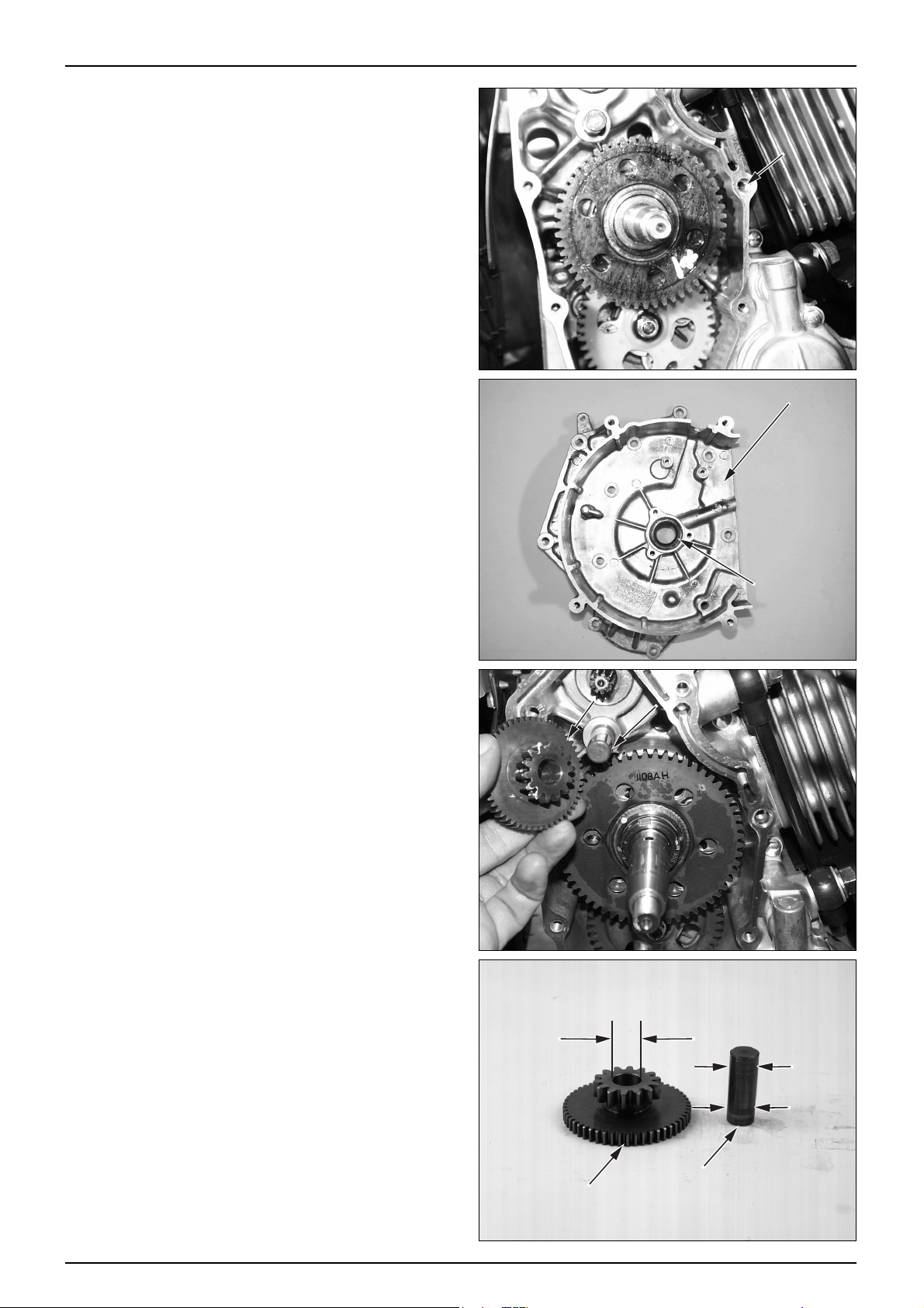
8-5
A.C GENERA T OR / STARTER CLUTCH
● Loosen the 9 RH. crankcase cover setting bolts.
● Remove the RH. crankcase cover.
● Remove the gasket and dowel pin.
● Remove the RH. crankcase cover oil seal.
● Check the oil seal for wear or damage and replace with
a new one as necessary .
STARTER REDUCTION GEAR
REMOV AL
● Remove the starter reduction gear and shaft.
INSPECTION
● Check the reduction gear for wear or damage.
● Measure the inner diameter of the gear.
SERVICE LIMIT : 12.10 mm
● Measure the outer diameter of the gear shaft.
SERVICE LIMIT : 11.97 mm
DOWEL PIN
RH. CRANKCASE COVER
OIL SEAL
REDUCTION GEAR
SHAFT
STARTER
REDUCTION GEAR
SHAFT
Page 90

8-6
A.C GENERA T OR / STARTER CLUTCH
ST ARTER REDUCTION GEAR INST ALLA TION
● Install the starter reduction gear and shaft.
● Remove the gasket residues from the RH. crankcase.
● Install a new gasket and dowel pin.
● Tighten the RH. crankcase cover with setting bolts.
● Install the following parts.
-A.C.Generator (⇨8-2 )
-Cooling fan (⇨8-2 )
-RH. shroud (⇨8-2 )
-Rear swing arm (⇨13-8 )
-Rear caliper (⇨14-6 )
-EX. muffler (⇨4-12 )
-RH. floor side cover (⇨4-7 )
-Luggage box (⇨4-4 )
● Tighten the rear cushion under bolt.
STARTER CLUTCH
REMOV AL
● Loosen the rear cushion under bolt.
● Remove the following parts.
-RH. floor side cover (⇨4-7 )
-RH. shroud (⇨8-2 )
-Cooling fan (⇨8-2 )
-A.C Generator (⇨8-2 )
-EX. muffler (⇨4-12 )
-Rear caliper (⇨14-6 )
-Rear swing arm (⇨13-8 )
-RH. crankcase cover (⇨8-4 )
● Remove the LH. crankcase cover and hold the drive
face with the drive face holder .
● Loosen the starter clutch lock nut with a special socket.
TORQUE VALUE : 9.5 kgf·m
TOOLS : SPECIAL SOCKET (12.7x28x120)
DRIVE FACE HOLDER
REDUCTION GEAR
SHAFT
RH. CRANKCASE COVER
STARTER CLUTCH
SPECIAL SOCKET
(12.7X28X120)
Page 91

8-7
A.C GENERA T OR / STARTER CLUTCH
● Remove the washer.
● Remove the starter driven gear and starter clutch.
● Check the starter driven gear and starter clutch for
proper operation.
● Remove the starter clutch.
ST ARTER CLUTCH INSPECTION
● Remove the starter driven gear, needle bearing and
starter oneway clutch set from the starter clutch
assembly .
● Check the starter driven gear for wear or damage.
● Measure the inner diameter of the starter driven gear.
SERVICE LIMIT : A : 32.10 mm
B : 39.53 mm
WASHER
STARTER CLUTCH
STARTER CLUTCH
STARTER
DRIVEN GEAR
STARTER ONEWAY
CLUTCH SET
A
B
Page 92

8-8
A.C GENERA T OR / STARTER CLUTCH
STARTER ONEWAY CLUTCH SET
ST ARTER CLUTCH INSTALLATION
● Install the starter oneway clutch set, starter driven gear
and needle bearing to the starter clutch assembly.
● Install the starter clutch to the RH. crankshaft.
NOTE
·When installing the starter clutch, match it with the
groove accurately
● Install the thrust washer.
● Temporarily install the starter clutch lock nut.
● Hold the drive face with the drive face holder.
● Tighten the starter clutch lock nut with a special socket.
NOTE
·Tighten the lock nut with specified torque.
TORQUE VALUE : 9.5 kgf·m
TOOLS : SPECIAL SOCKET (12.7x28x120)
DRIVE FACE HOLDER
● Install the following parts.
-RH. crankcase cover (⇨7-2 )
-A.C Generator (⇨8-2 )
-Cooling fan (⇨8-2 )
-RH. shroud (⇨8-2 )
-Rear swing arm (⇨13-8 )
-Rear caliper (⇨14-6 )
-EX. muffler (⇨4-12 )
-RH. floor side cover (⇨4-7 )
-LH. crankcase cover (⇨7-2 )
● Tighten the rear cushion upper bolt.
LOCK NUT
SPECIAL SOCKET
RH. CRANKCASE
COVER
Page 93
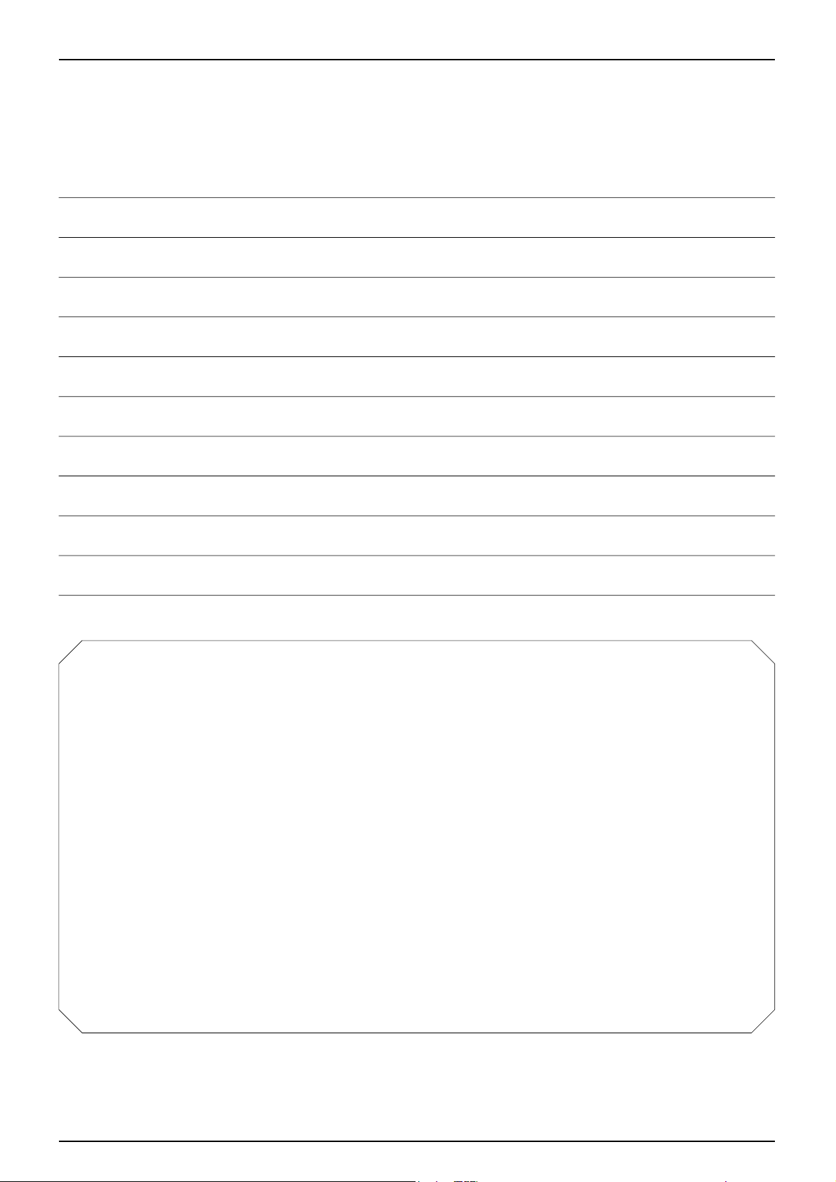
MEMO
Page 94

9-0
CYLINDER HEAD / V AL VES
CAMCOVERPLATE
IN.VALVEROCKERARM
EX.VALVEROCKERARM
CAMSHAFTHOLDER
CAMSHAFTCOMP
CARBURETORINSULATOR
CYLINDERHEADCOMP
CYLINDERHEADGASKET
INLETVALVE
EX.VALVE
Page 95

9-1
9. CYLINDER HEAD / VALVES
SERVICE INFORMATION
GENERAL SAFETY
● The rocker arm and the camshaft can be serviced without removing the engine. However, the engine must be removed
from the frame to maintain the cylinder head.
● The oil of camshaft oil is supplied through the cylinder head oil hole. Clean the oil hole prior to assembling the cylinder
head.
SPECIFICA TIONS
9
SERVICE INFORMATION
····
9-1
TROUBLESHOOTING
········
9-2
CAMSHAFT
················
9-3
CYLINDER HEAD
··········
9-5
VALVE SPRINGS
············
9-6
VALVES
··················
9-6
VALVE GUIDES
············
9-7
VALVE SEATS
············
9-8
CYLINDER HEAD ASSEMBLY··9-11
CAMSHAFT ASSEMBLY
······
9-13
TORQUE VALUES
CAM CHAIN TENSIONER PIVOT BOLT 1.0 kgf·m
SPARK PLUG 1.2 kgf·m
CAMSHAFT HOLDER 8mm NUT 2.0 kgf·m
CAM CHAIN TENSIONER MOUNTING BOLT 1.2 kgf·m
CAM CHAIN TENSIONER SEALING SCREW 0.4 kgf·m
CYLINDER HEAD COVER BOLT 0.9 kgf·m
CYLINDER HEAD BOLT 1.1 kgf·m
TAPPET ADJUST NUT 0.8 kgf·m
ITEM STANDARD VALUE SERVICE LIMIT
Unit : mm
ROCKER ARM
CAM HEIGHT
VALVE STEM OUTER DIAMETER
CLEARANCE BETWEEN
STEM AND GUIDE
CAMSHAFT
VALVE
VALVE GUIDE
ROCKER ARM INNER DIAMETER 12.016 - 12.034 39.05
ROCKER ARM SHAFT OUTER DIAMETER 11.982 - 12.000 11.950
IN 33.835 - 33.995 33.625
EX 33.984 - 34.144 33.765
CAMSHAFT OUTER DIAMETER 15.005 - 15.018 15.040
VALVE SPRING FREE LENGTH IN,EX 37.21 36.90
IN 4.972 - 4.984 4.920
EX 4.952 - 4.964 4.900
VALVE GUIDE INNER DIAMETER IN,EX 5.000 - 5.012 5.030
IN 0.016 - 0.040 0.090
EX 0.036 - 0.060 0.120
VALVE SEAT WIDTH 0.8 - 1.0 1.4
CYLINDER HEAD WARPAGE - -
Page 96

TOOLS
VALVE GUIDE REAMER
VALVE GUIDE DRIVER
VALVE SPRING COMPRESSOR
VALVE SEAT CUTTER
SEAT CUTTER IN 37°(21.5mm)
EX 37°(18.5mm)
IN 45°(22.0mm)
EX 45°(22.0mm)
IN 55°(20.0mm)
EX 55°(20.0mm)
TROUBLESHOOTING
Enging top-end problems useally affect engine performance. These can be diagnosed by a compression or leak down test,
or by tracing noises to the top-end with a sounding rod or stethoscope.
9-2
CYLINDER HEAD / V AL VES
Low comperssion
● Valves
-Incorrect valve adjustment (see section 3)
-Burned or bent valves
-Incorrect valve timing
-Broken valve spring
-Uneven valve seating
● Cylinder head
-Leaking or damage head gasket
-W arped or cracked cylinder head
● Cylinder, piston (see section 10)
Excessive white smoke
● Worn valve guide or valve stem
● Damaged valve stem seal
● Worn or damaged piston ring
Rough idle
● Low cylinder compression
Compression too high
● Excessive carbon build-up on piston or combustion
chamber
Excessive noise
● Incorrect valve adjustment
● Sticking valve or broken valve spring
● Damaged or worn camshaft
● Worn rocker arm and / or shaft
● Loose or worn cam chain
● Worn or damaged cam chain tensioner
● Damaged cylinder head gasket
● Incorrect spark plug installation
Page 97

CAMSHAFT
REMOV AL
● Remove the luggage box. (⇨4-4 )
● Remove the center cover. (⇨4-5 )
● Loosen the cylinder head cover bolts, remove the cover.
● Remove the shroud grommet B of the fan cover.
NOTE
·The camshaft can be maintained without removing
the engine.
● Turn the crankshaft to the left, and align the “T”mark
of the flywheel with the index mark of the RH.
crankcase cover .
● Verify that the piston is located at the top dead center.
(Make all camshaft lobes face downward.)
● If all camshaft lobes face upward, rotate the crankshaft
to the left for 1 turn (360°), and align the “T” mark
with the index mark once again.
● Loosen the pan screw of the cam chain, remove the
tensioner flange bolts and tensioner lifter .
● Loosen the 4 camshaft holder 8mm nuts.
● Remove the cam cover plate.
● Remove the camshaft holder from the cylinder head.
9-3
CYLINDER HEAD / V AL VES
CYLINDER HEAD COVER
"T" MARK
PAN SCREW
CAM CHAIN
TENSIONER
FLANGE BOLT
NUT
CAM COVER PLATE
Page 98

● Remove the cam chain from the camshaft.
NOTE
·Take precautions not to allow the cam chain to drop
into the crankcase.
● Remove the camshaft.
● Insert the 6mm bolt into the rocker arm shaft, and
pulling bolts to remove the rocker arm shaft.
● Remove the rocker arm.
● Remove the other side rocker arm shaft and rocker arm
in the same sequence.
CAMSHAFT INSPECTION
● Check the rocker arm and rocker arm shaft for wear or
damage.
● Measure the inner diameter of the rocker arm.
SERVICE LIMIT : 12.060 mm
● Measure the outer diameter of the rocker arm shaft.
SERVICE LIMIT : 11.950 mm
● Check the cam lobes of the camshaft for wear or
damage.
● Measure the height of the cam lobe.
SERVICE LIMIT : IN : 33.625 mm
EX: 33.765 mm
9-4
CYLINDER HEAD / V AL VES
CAM CHAIN
ROCKER
ARM
CAM SHAFT HOLDER
ROCKER ARM SHAFT
CAM SHAFT
Page 99

● Manually turn the camshaft bearing outer race, and
check if it turns smoothly .
● Check the bearing for wear or damage.
CAUTION
·Be sure to check the valve clearance.
CYLINDER HEAD
REMOV AL
● Remove the engine from the frame. (⇨6-2 )
● Remove the cylinder head cover.
● Remove the RH. LH. shroud. (⇨8-2 )
● Remove the camshaft. (⇨9-3 )
● Remove the EX. pipe. (⇨4-12 )
● Remove the cylinder head.
● Remove the cylinder head gasket, dowel pin and cam
chain guide from the cylinder .
DISASSEMBLY
● Remove the carburetor insulator.
● Remove the spark plug from the cylinder head.
9-5
CYLINDER HEAD / V AL VES
CAMSHAFT BEARING
CYLINDER
HEAD
CAM CHAIN GUIDE
CARBURETOR INSULATOR
Page 100

● Remove the valve spring, valve cotter, retainer, spring
and valve. Using the valve spring compressor .
TOOL : VALVE SPRING COMPRESSOR
NOTE
·To prevent the loss of tension, do not compress the
valve spring more than necessary .
·Mark the disassembled parts so that they can be
reassembled into the original position later .
● Remove the valve spring seat and valve stem seal.
Remove carbon deposits from the inside of the
combustion chamber .
CYLINDER HEAD INSPECTION
● Remove gasket marks from the cylinder head gasket.
NOTE
·Take precautions not to damage the cylinder head
gasket attachment.
● Check the spark plug assembling hole and the valve
seat for cracks.
● Using a square and a feeler gauge, check the cylinder
head distortion.
SERVICE LIMIT : 0.1 mm
VALVE SPRINGS
● Measure the free length of the inner and outer valve
springs.
SERVICE LIMIT : 36.90 mm
NOTE
·Replace the valve spring with new one if the length
of any one is less than the service limit.
VALVES
● Inspect each valve for bending, burning, scratches or
abnormal wear.
● Insert the valves in their original positions in the
cylinder head.
Check that each valve moves up and down smothly,
without binding.
● Measure and record the valve stem outer diameter in
three places along the valve guide sliding area.
SERVICE LIMIT : IN : 4.920 mm
EX: 4.900 mm
● Replace the valve with a new one if the service limit is
exceeded.
9-6
CYLINDER HEAD / V AL VES
VALVE SPRING
COMPRESSOR
 Loading...