

Page 1
Page 2
HOW TO USE THIS MANUAL
This manual describes effective maintenance procedure
for the S-Five manufactured by DAELIM Motor Co., Ltd.
To ensure safety and optimal operating conditions of the
vehicle, carry out regular inspections according to the
maintenance schedule (Section 2).
Sections 1 through 2 provide information on overall
vehicle; section 3, assembly and disassembly procedures
for external components, and section 4 describes
maintenance procedure for the engine, frame and electrical
systems.
To facilitate use of this manual, each page starts with
disassembly and system diagrams, service information,
and troubleshooting guide. If you cannot find the cause of
trouble, refer to Section 18: Troubleshooting.
Contents of this manual and specifications are
subject to change without prior notice for
improvement of vehicle quality .
No part of this publication may be reproduced
without written permission of DAELIM Motor Co.,
Ltd.,
CONTENTS
SERVICE INFORMATION
INSPECTIONS/ADJUSTMENTS
EXTERNAL P ARTS
LUBRICA TION SYSTEM
FUEL SYSTEM
ENGINE REMOVAL/INST ALLATION
KICK STARTER/ CONTINUOUSLY
VARIABLE TRANSMISSION
CYLINDER HEAD/CYLINDER/PISTON
TRANSMISSION/CRANKSHAFT/CRANK CASE
FRONT WHEEL/FRONT FORK/STEERING
REAR WHEEL/BRAKE/SUSPENSION
BRAKE SYSTEM
GENERAL
ENGINE
FRAME
ELECTRICAL SYSTEM
BATTERY/CHARGING SYSTEM
STARTING SYSTEM
LIGHTS/METER/SWITCHES
IGNITION SYSTEM
1
2
3
4
5
6
7
8
9
10
11
12
13
14
15
16
WIRING DIAGRAM
17
TROUBLESHOOTING
18
Page 3
1-1
1. SERVICE INFORMATION
GENERAL SAFETY 1-1
SERVICE RULES
1-1
CAUTION WHEN WIRING
1-5
SERIAL NUMBER LOCATION
1-9
MAINTENANCE INFORMATION
1-10
TWIST TORQUE
1-14
SPECIALIZED TOOLS
1-16
LUBRICATION OIL
1-17
SYMBOLS
1-18
WIRING DIAGRAM
1-19
GENERAL SAFETY
WARNING
1. Do not run the engine for a long time in closed or not well-ventilated area because the exhaust gas contains toxic
substances such as carbon monoxide, hydrocarbon, nitric oxide.
2. The battery fluid(lean sulfuric acid) is extremely toxic. It is dangerous if skin is exposed to it or if it enters into the eye.
Be careful in handling. When exposed to the battery fluid, wash it with water and get a medical check up.(store the
battery fluid in a safe place to avoid touching by the children)
3. Pay attention not to be burned and always put on the protection gears because the engine or the muffler is hot right after
engine stops.
4. Gasoline is extremely flammable. Maintenance must performed in the place free of the open fire or electric spark.
5. When more than two person are working, always pay attention to other worker’s action and alway have safety in mind.
6. The skin exposed to used engine oil can be a major reason of the skin cancer. Pay attention not to exposed and wash
carefully with soap and water after handling.
7. If compressed air is used to clean the brake, dust scattered in the air can be breathed in by workers. Please take action not
to scatter dust in the brake cleaner, etc.
8. Flammable nitrogen gas is generated during charging the battery so charging must be performed in well-ventilated area
and free of the open fire and spark.
SERVICE RULES
1. Parts and lubrication oil must be DAELIM genuine or
recommended parts.
2. Before maintenance, remove deposit or dust from the
chasis.
1
Page 4
1-2
SERVICE INFORMATION
9. Check to see if the rubber part is worn out when
removing it and replace it if necessary . Some rubber part
is weak to gasoline and kerosene, so pay attention not to
soak with gasoline or oils.
10. Recommended grease must be applied to or filled in
the specified place.
7. Align the bolts to uniform the tightening points before
tightening them when you don’t know the bolt length.
8. Bolts, nuts and pieces must be tightened from the bigger
diameter to the smaller one, from inside to outside and
diagonally with the specified torque.
5. Clean the parts after the overhaul and before the test and
remove the cleaning oil with compressed air. Apply oil
to seal face during installation.
6. Check necessary place and measure necessary data
during installation. When installing, return to the state
before removing.
3. Store the parts of each system discriminatively to install
each part in the right place.
4. After removing gasket, O-ring, piston pin clip and cotter
pin, always replace them with the new one. When
removing the snap ring, it can be easily missed after
transformation or installation.
Page 5
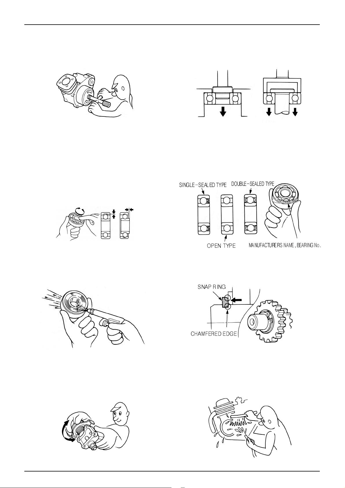
1-3
SERVICE INFORMATION
11. Maintenance needed to use the specialized tools must
performed with the right tool.
12. Never reuse the ball bearing removed with the ball
applied pressure when removing press-fitted the
bearing.
13. Check the smooth rotation of inner or outer race of the
ball bearing by rotating it manually .
• Replace the ball bearing having excessive axial/
longitudinal hanging.
• Wipe the ball bearing likely to have hanging with
cleaning oil.(except double-sided sealed type ball
bearing)
• Replace the ball bearing of which press-fitted part is
slacked at the case or shaft.
14. Pay attention to installation direction in case of the
single-sided sealed ball bearing. Install the opendirection or double-sided sealed bearing in the way
that the face marked with manufacturer and size
should direct to the outer axle.
15. When blowing the ball bearing with compressed air
after cleaning, keep the race from rotating. High speed
rotation of the race may damage the bearing. Prior to
installation, apply oil or grease to the bearing.
16. Install the snap ring so that chamfered side directs to
the load-applied side. After installation, check the
proper installation by rotating the snap ring.
17. Check each part for proper tightening and operation
after installation.
18. The brake fluid and coolant can damage the painted
plastic or rubber parts. Keep these parts from
contacting with them and wash these parts with water
in case of contact.
’
Page 6
1-4
SERVICE INFORMATION
21. Keep the pneumatic system interior or the engine
interior from the infiltration of dust.
22. Install the gasket mounted in the contact surface of
each case of the engine while removing gasket
material completely. Remove damaged contact surface
by wiping with the oil stone equally .
19. Install the oil seal so that the manufacturer marked
surface directs outer surface.(direction not covered
with oil)
• Pay attention not to bend or damage the lip
• Apply the grease to the lip
20. Connect the tube until the tube fully inserted in the
joint. Install the clip if it is supplied. Replace the tube
having slacked end.
23. Pay attention not to bend the cable excessively.
Transformed or damaged cable may cause malfunction
or damage.
24. Install the boots with the installing groove by inserting
the boots into the groove.
’
Page 7
1-5
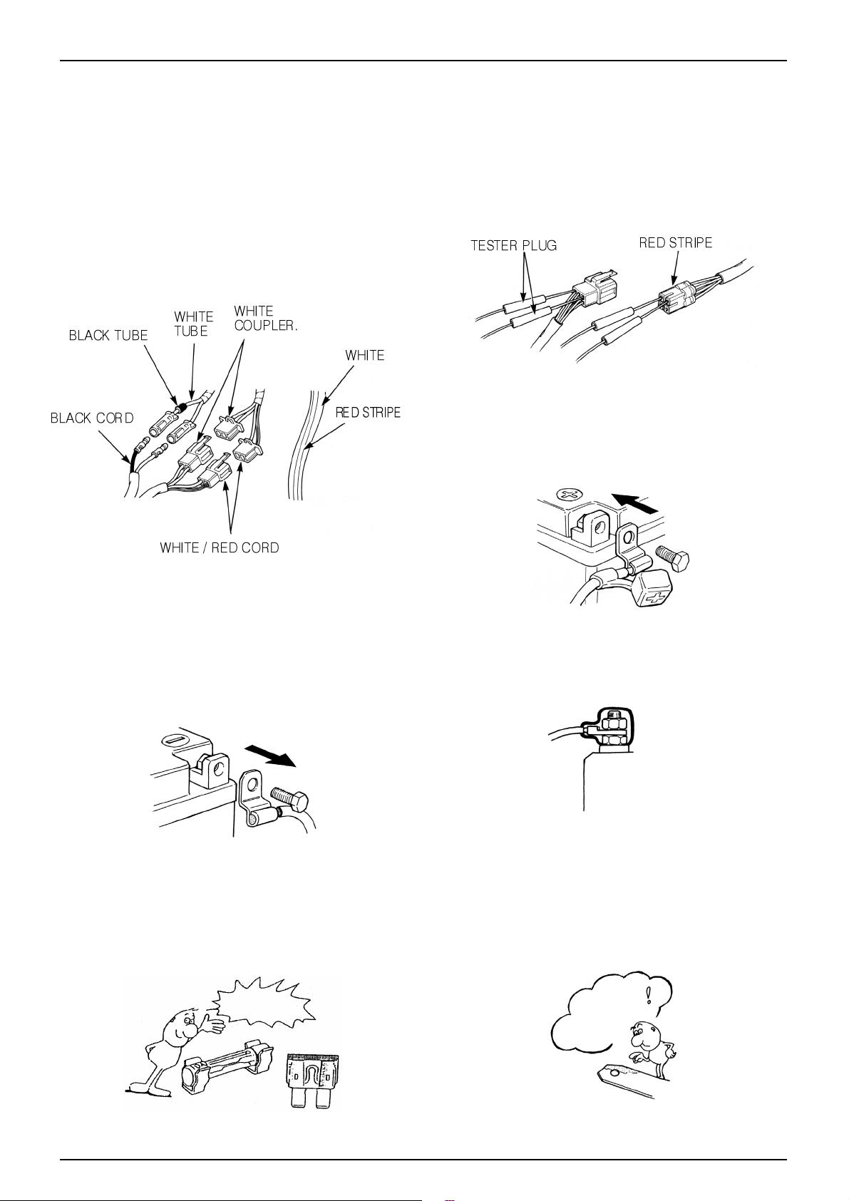
SERVICE INFORMATION
•Each cord must be connected depending on its color.
When connecting different cord, attach color tube
around the connector. Connect the coupler to the
connector with same color and same pin number .
•Identify the two-colored cord by main color first and
then spriped color .
•When measuring voltage or resistance of the cord
terminal using tester, contact the tester plug behind of
the coupler. Pay attention not to open the cord terminal
and contact the tester plug from the front of the coupler
in case of water-proof coupler.
•Recheck the condition of contact, securing and
continuity of each part after maintenance.
•When connecting the battery, the plus terminal must be
connected first.
•After connecting the terminal, apply the grease to the
terminal.
•When disconnecting the battery, the minus terminal
must be disconnected first.
•Make sure that the tool such as spanner do not contact
with the frame.
•Connect covers to the terminal after maintenance.
•If the fuse is short-circuited, find out the cause and
repair. Replace with the fuse having the specified
capacity .
•If there is rust in the terminal, remove the rust with sand
paper prior to connecting.
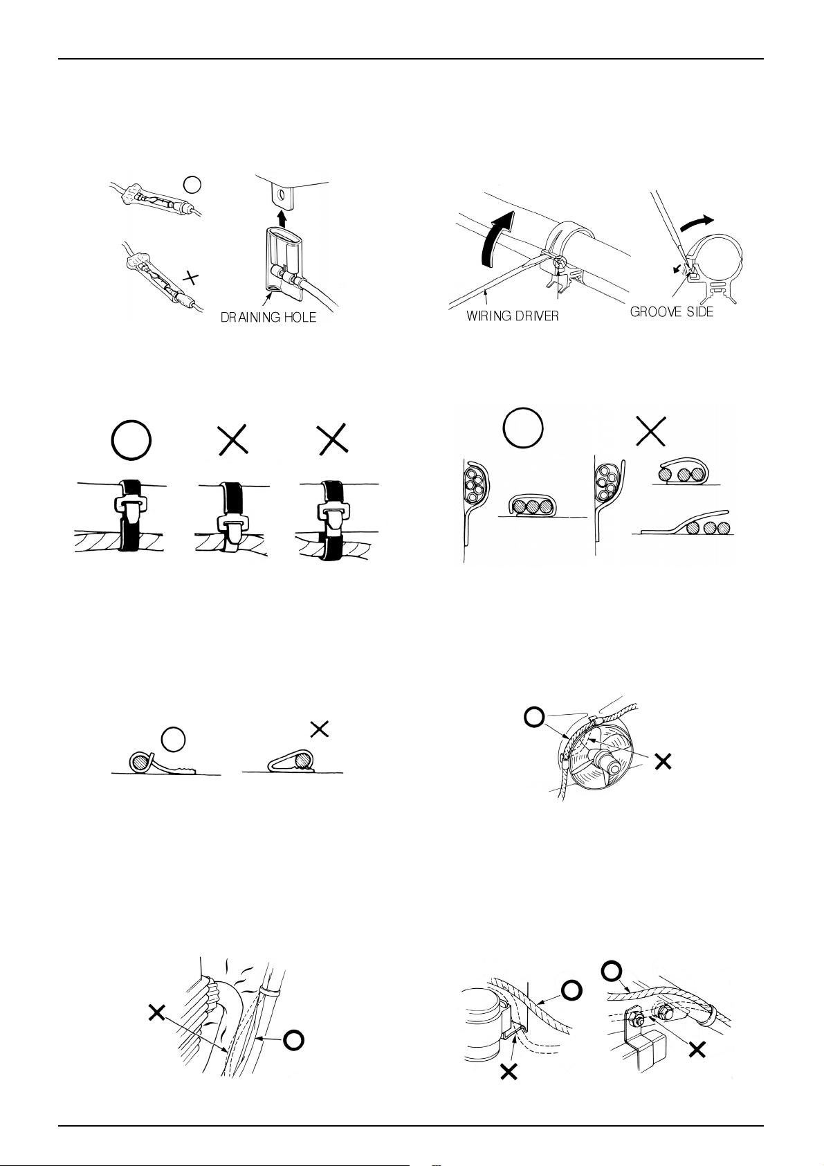
CAUTION WHEN WIRING
VALIDATION
OF CAPACITY!
REMOVE
THE
RUST!
Page 8
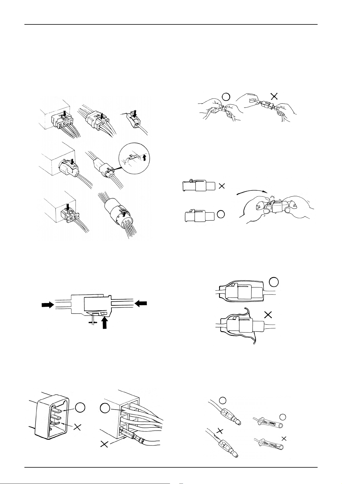
1-6
SERVICE INFORMATION
•Insert the lock of the coupler until the lock is fully
secured.
•Turn off the main switch before connecting/disconnecting.
•Release the lock to disconnect the lock of the coupler.
•The lock of the coupler has two types according to
releasing method(press type and pull type) so release it
properly according to the shape.
- Typical releasing method of the coupler is illustrated in
the following.
•When disconnecting the coupler, disconnect it while
holding the coupler body. Pull while holding the wire
harness cord and do not remove the coupler connection.
•Release the lock by inserting the coupler slightly and
then narrowing connection to remove the coupler .
•Pay attention not to damage the vinyl cover of the
coupler.
•Check to see if there is bended terminal and secure it to
avoid disconnecting.
•If the wire harness coating is damaged, repair by
winding vinyl tape or replace it.
•Prior to connecting the connector, make sure that the
cover is not damaged and the mess terminal is not
opened.
Page 9
1-7
SERVICE INFORMATION
•Wire band must be secured firmly in the specified
location of the frame. In case of aluminium band,
secure the wire harness to the coated part.
•Secure the wire harness firmly using the clamp.
•Insert the connector until the vinyl cover is fully
inserted into the terminal.
•The opening of the vinyl cover must face at the ground
direction but in case of the plain connector, the draining
opening must face at the sky direction.
•When removing T-start, broaden the groove of T-start
using the wiring driver and release the torque.
•Connect the harness and the hose to T-start and then
insert until the groove is locked.
•When removing T-start from the frame, replace it with
the new one.
•In case of the weld clamp, do not clamp in the welded
part.
•When clamping the wire harness, make sure that the
harness is not contacted with the shaft or rotating part.
•When clamping the wire, pay attention not to contact
with hot part.
•The wire harness must be routed without contacting
with the end of the lamp or any sharp edge.
•The wire harness must be routed without contacting
with the end of the bolt or the piece.
Page 10
1-8
SERVICE INFORMATION
•If necessary, lock the wire harness properly . •When mounting parts, make sure that the wire harness
is not pressed by the parts.
•In case that the wire harness is contacted with the end or
the sharp edge, protect both parts with tube or tape.
•The wire must not hang down or be pulled excessively.
•Do not twist the wire harness. •Wire the wire harness not to be pulled or expanded
when the handle is turned to the right or the left
completely. Avoid excessive bending or chewing and
interference with the engine.
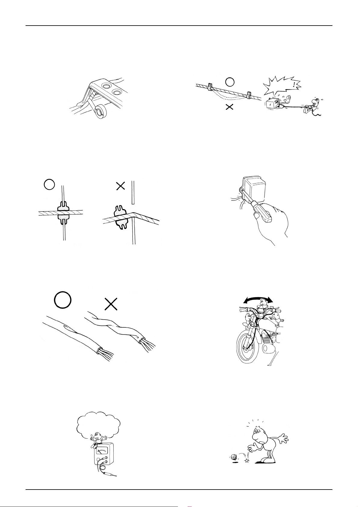
•Prior to using the tester, please read the manual care-
fully and understand the contents.
•When testing the resistance of the tester, the zero
adjustment must be performed before testing.
•Do not drop or throw the parts especially
semiconductor contained parts because these parts may
be damaged by the impact of the drop.
NOT TO
PULL!
Is this
measurement range or
configuration in accord
with the manual?
Page 11
1-9
SERVICE INFORMATION
SERIAL NUMBER LOCATION
ENGINE SERIAL NUMBER LOCA TION FRAME SERIAL NUMBER LOCA TION
Page 12
1-10
SERVICE INFORMATION
MAINTENANCE INFORMATION
SPECIFICA TIONS
MAINTENANCE SPECIFICA TIONS
TYPE OF VEHICLE
OVERALL LENGTH
OVERALL WIDTH
OVERALL HEIGHT
WHEEL BASE
MOTOR TYPE
DISPLACEMENT
FUEL TYPE
FRONT AXLE
REAR AXLE
TOTAL
PASSENGERS
FRONT AXLE
REAR AXLE
TOTAL
GROUND CLEARANCE
CASTER
TRAIL
S-Five
1,795mm
698mm
1,114mm
1,260mm
SJ50E
49.5cc
UNLEADED GASOLINE
36.5kg
57.5kg
94kg
2(75kg)
58.5kg
100.5kg
159kg
131mm
26。
79mm
FRAME TYPE
BRAKING DISTANCE
MIN. REVOLUTION RADIUS
COOLING TYPE
STARTING
MOTOR TYPE
NO. OF CYLINDERS, MOUNTING
VALVE APPARATUS
BORE & STROKE
COMPRESSION RATIO
MAX. OUTPUT
MAX. TORQUE
PRIMARY SPEED REDUCTION RATIO
SECONDARY SPEED REDUCTION RATIO
TRANSMISSION
TRANSMISSION RATIO 1ST GEAR
FRAME NUMBER
ENGINE NUMBER
UNDER BONE
8.0m(30km/h VELOCITY)
1,800mm
AIR-COOLED
ST ARTER MOTOR, KICK
2-CYCLE
1 CYLINDER, TRANSVERSE
READ VAL VE PIST ON VALVE COMBINA TION
39.0X41.4mm
6.8:1
5.1PS/7,000rpm
0.55kgf·m/7,000rpm
4.083
3.615
GEARLESS TRANSMISSION
2.4~0.76
KMYSE1B4S1K000001~
SJ50E3000001~
DRY WEIGHT
GROSS WEIGHT
ITEM STANDARD
LUBRICATION SYSTEM
ENGINE OIL TANK CAPACITY FULL CAPACITY
RECOMMENDED ENGINE OIL
TRANSMISSION OIL CAPACITY FULL CAPACITY
RECOMMENDED TRANSMISSION OIL
LUBRICATION TYPE
OIL FILTER TYPE
OIL PUMP TYPE
COOLING TYPE
COOLING TYPE
1.2 liters
DMC Ultra 2 super oil, 2-Cycle Oil
0.09 liters
DMC Pure Mission Oil or
SAE 80W/90
Separation Lubrication
Current Filtration,
Plunger Type
Air-Cooled
USE LIMITS
Page 13
1-11
SERVICE INFORMATION
ITEM STANDARD
FUEL SYSTEM
FUEL TANK CAPACITY FULL CAPACITY
AIR CLEANER TYPE
CARBURETOR SETTING MARK
VENTURI DIAMETER
AIR SCREW OPENING
FLOAT LEVEL
IDLING RPMS
NO. OF JET NEEDLES
MAIN JET
SLOW JET
THROTTLE GRIP CLEARANCE
CYLINDER HEAD, CYLINDER, PISTON
PORT OPEN/CLOSE PERIODS INHALATION OPEN
CLOSE
EXHAUST OPEN
CLOSE
SCAVENGING OPEN
CLOSE
CYLINDER HEAD COMPRESSION PRESSURE
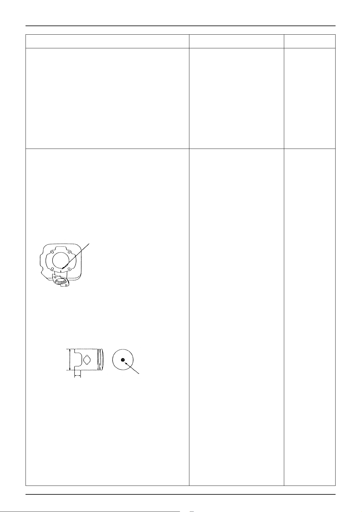
CYLINDER ID MARK LOCATION
INSIDE DIAMETER ID MARK(A)
NO ID MARK
CYLINDRICAL DEGREE
OUT OF ROUNDNESS
PISTON
OUTSIDE DIAMETER MEASUREMENT LOCATION
OUTSIDE
DIAMETER
OUTSIDE DIAMETER ID MARK(A)
ID MARK(B)
NO ID MARK
CYLINDER AND PISTON CLEARANCE
PISTON PIN HOLE INSIDE DIAMETER
PISTON PIN OUTSIDE DIAMETER
PISTON AND PISTON PIN CLEARANCE
PISTON RING GAP TOP
SECOND
RING MARK
CONNECTING ROD SMALL END PORTION DIAMETER
6ℓ
Urethane Foam
PB11P
16.0mm
1 1/4 Rotation
8.0mm
1,800±100rpm
4
#75
#38
2-6mm
Auto Control
Auto Control
81.5。BBDC
81.5。ABDC
56.5。BBDC
56.5。ABDC
10kgf/㎠-600rpm
Side of Cylinder
39.000-39.005mm
39.005-39.010mm
-
-
38.955-38.960mm
38.965-38.970mm
38.960-38.965mm
0.035-0.050mm
12.002-12.008mm
11.994-12.000mm
0.002-0.014mm
0.10-0.25mm
0.10-0.25mm
Turning up
17.005-17.017mm
-
-
-
-
-
-
-
-
-
-
-
-
-
-
-
-
-
-
39.05mm
39.05mm
0.10mm
0.10mm
38.90mm
38.90mm
38.90mm
0.10mm
12.03mm
11.98mm
0.03mm
0.40mm
0.40mm
-
17.03mm
USE LIMITS
3mm
Page 14
1-12
SERVICE INFORMATION
ITEM STANDARD
CLUTCH
CLUTCH AUTOMATIC
TYPE
CLUTCH OUTER DIAMETER
CLUTCH LINING THICKNESS
DRIVE BELT WIDTH
MOVABLE DRIVE FACE
BUSH INSIDE DIAMETER
BOSS OUTSIDE DIAMETER
WEIGHT ROLLER OUTSIDE DIAMETER
DRIVEN PULLEY FACE SPRING FREE LENGTH
FACE OUTSIDE DIAMETER
MOVABLE FACE INSIDE DIAMETER
CRANK SHAFT
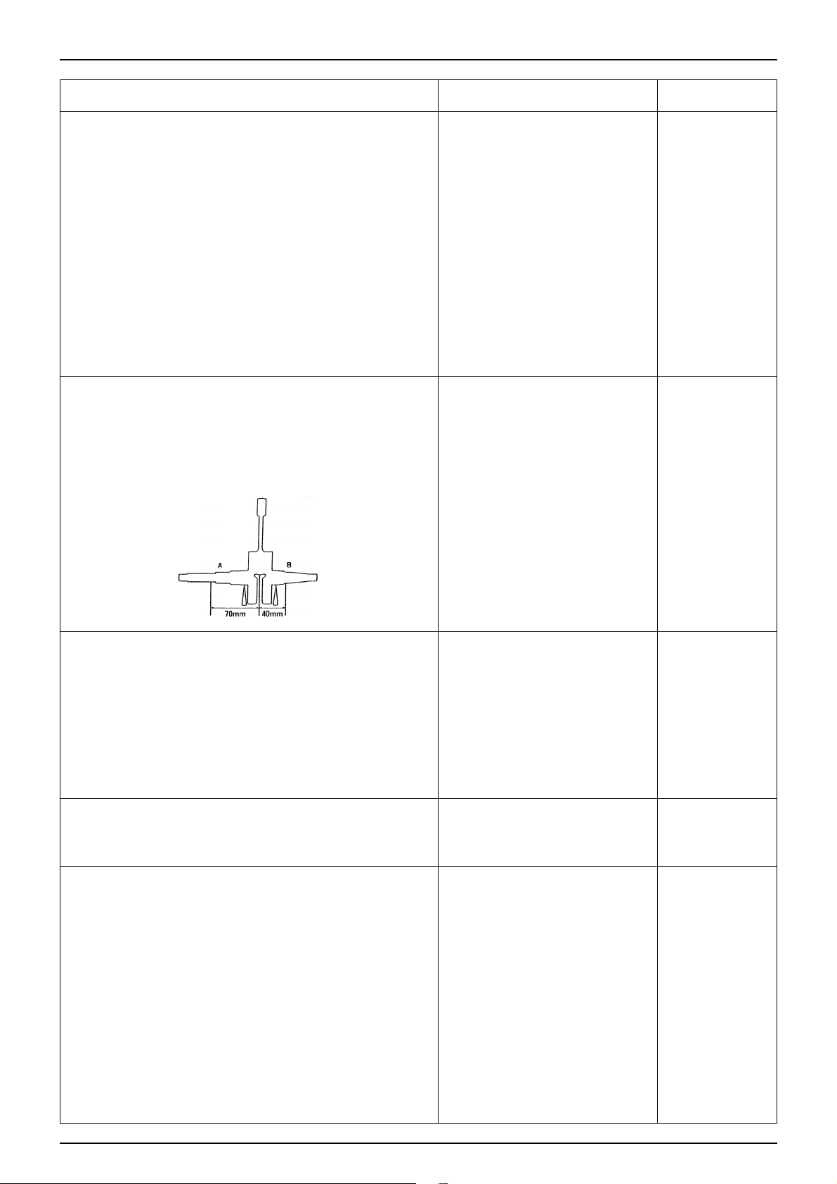
CRANK SHAFT LARGE END SIDE CLEARANCE
CONNECTING ROD LARGE END RIGHT
ANGLE DIRECTION CLEARANCE
CRANK SHAFT SHAKING A
B
FRONT, REAR WHEELS
WHEELS
RIM RUNOUT RADICAL
AXIAL
AXLE DEFLECTION
TIRES TYPE
TIRE PRESSURE FRONT
REAR
TIRE SIZE FRONT
REAR
SUSPENSION
FRONT FRONT CUSHION FREE LENGTH
REAR REAR CUSHION FREE LENGTH
BRAKES
FRONT BRAKE LEVER FREE PLAY
BRAKE FLUID
BRAKE PAD THICKNESS
DISK THICKNESS
DISK SHAKING
DISK WEAR LINE
MASTER CYLINDER INSIDE DIAMETER
MASTER PISTON OUTSIDE DIAMETER
CALIPER CYLINDER INSIDE DIAMETER
CALIPER PISTON OUTSIDE DIAMETER
REAR BRAKE LEVER FREE PLAY
DRUM INSIDE DIAMETER
LINING THICKNESS
Automatic Centrifugal
Continuously Variable Transmission
107.0-107.2mm
3.0mm
17.5mm
20.035-20.085mm
20.011-20.025mm
15.920-16.080mm
98.1mm
33.965-33.985mm
34.000-34.025mm
0.15~0.55mm
0.010~0.02mm
0.03mm(70mm fromcenter)
0.05mm(40mm fromcenter)
-
-
TUBELESS
1.75㎏
f/㎠ (2.00㎏f/㎠)
2.00㎏
f/㎠ (2.25㎏f/㎠)
120/70-12 58L
130/70-12 62L
263.5mm
234.8mm
10~20mm
DOT3 or DOT4
-
3.5mm
-
3.0mm
11.000-11.043mm
10.957-10.984mm
30.230-30.280mm
30.148-30.198mm
10~20mm
110mm
4.0mm
-
-
107.5mm
2.0mm
16.5mm
20.60mm
19.97mm
15.40mm
92.8mm
33.94mm
34.06mm
0.60mm
0.04mm
0.15mm
0.10mm
2.0mm
2.0mm
0.2mm
-
-
-
-
256.0mm
228.0mm
-
to wear line
3.0mm
0.3mm
11.05mm
10.91mm
30.29mm
30.14mm
111mm
2.0mm
USE LIMITS
Page 15

1-13
SERVICE INFORMATION
ITEM STANDARD
B8HSA
0.6~0.7mm
BTDC 17。±2。/1,800rpm
over 120V
over 120V
over 1.5V
0.1-0.5Ω
6.5-9.5
㏀㏀
2.6±1.25
㏀㏀
500Ω±20%
100Ω±20%
AC
12V-9.5A/5,000rpm
0.8Ω±20%
0.55Ω±20%
Semi-conductor
12.6-13.6V/5,000rpm
14.0-15.0V/5,000rpm
6.3-7.1Ω
5.5-6.5Ω
12V-35/35W
12V-5/21W
12V-16W×2
12V-10W×2
12V-5W
12V-5W
12V-1.7W×2
14V-3W
14V-3W
14V-3W×2
7A
MF BATTERY
12V-3AH
13.0-13.2V
0.4A/5h
4A/0.5h
USE LIMITS
IGNITION SYSTEM
SPARK PLUG STANDARD
PLUG GAP
IGNITION TIMING F MARK
PEAK VOLTAGE IGNITION COIL(PRIMARY VOLTAGE)
EXCITE COIL
PULSE GENERATOR
IGNITION COIL RESISTANCE VALUES(20℃)
PRIMARY COIL
SECONDARY COIL
(PLUG CAP CONNECTION)
SECONDARY COIL
(PLUG CAP DISCONNECTION)
EXCITE COIL RESISTANCE VALUE(20℃)
PLUSE GENERATOR RESISTANCE VALUE(20℃)
CHARGING SYSTEM, AC GENERATOR
AC GENERATOR TYPE
OUTPUT
CHARGING COIL RESISTANCE VALUE(20℃)
LIGHTING COIL RESISTANCE VALUE(20℃)
REGULATOR/RECTIFIER
TYPE
CONTROL VOLTAGE LAMP SIDE
CHARGING SIDE
REGISTER RESISTANCE VALUE
REGISTER(6.7Ω 5W)
REGISTER(5.9Ω 30W)
LIGHTS, METER, SWITCHES
LIGHTS, BULBS HEADLIGHT
TAIL/STOP LIGHT
WINKER LIGHTS FRONT
REAR
POSITION LAMP
LICENSE LAMP
METER LIGHTS
HIGH BEAM PILOT
OIL PILOT
WINKER PILOTS
FUSE
BATTERY
TYPE
CAPACITY
TERMINAL VOLTAGE(20℃)
CHARGING CURRENT/STANDARD
CHARGING CURRENT/RAPID
Page 16
1-14
SERVICE INFORMATION
TWIST TORQUE
ST ANDARD TWIST T ORQUE
ENGINE P ARTS
TYPE
5mm BOLT, NUT
6mm BOLT, NUT
8mm BOLT, NUT
10mm BOLT, NUT
12mm BOLT, NUT
TWIST TORQUE
0.5㎏f·m
1.0㎏f·m
2.2㎏f·m
3.5㎏f·m
5.5㎏f·m
TYPE
5mm SCREW
6mm SCREW
6mm SCREW FLANGE BOLT, NUT
8mm SCREW FLANGE BOLT, NUT
10mm SCREW FLANGE BOLT, NUT
TWIST TORQUE
0.4㎏f·m
0.9㎏f·m
1.2㎏f·m
2.7㎏f·m
4.0㎏f·m
TWIST PART
FLY WHEEL NUT
DRIVE FACE NUT
CYLINDER HEAD BOLT
SPARK PLUG
DRIVEN FACE NUT
CLUTCH OUTER NUT
OIL LEVEL CHECK BOLT
EXHAUST PIPE JOINT NUT
MUFFLER BRACKET BOLT
CRANK CASE BOLT
NUMBER
1
1
4
1
1
1
1
2
2
6
TWIST TORQUE
4.0㎏f·m
5.5㎏f·m
1.0㎏f·m
1.4㎏f·m
5.5㎏f·m
4.0㎏f·m
1.3㎏f·m
1.2㎏f·m
3.3㎏f·m
1.0㎏f·m
REFERENCESCREW DIAMETER (mm)
10
12
6
14
28
10
8
6
8
6
Bolts not appearing in the following table are tightened using standard torque.
Page 17

1-15
SERVICE INFORMATION
FRAME P ARTS
TWIST PART
STEERING STEM LOCK NUT
HANDLE POST TWIST NUT
FRONT BRAKE LEVER PIVOT BOLT
FRONT BRAKE LEVER PIVOT NUT
REAR BRAKE LEVER PIVOT SCREW
REAR BRAKE LEVER PIVOT NUT
MASTER CYLINDER HOLDER BOLT
MASTER CYLINDER COVER SCREW
BRAKE HOSE BOLT
CALIPER MOUNT BOLT
CALIPER BREATHER VALVE
CALIPER PAD PIN
CALIPER SLIDE PIN BOLT
BRAKE SWITCH SCREW
STEERING STEM BOLT(FRONT FORK SIDE)
FRONT AXLE NUT
REAR AXLE NUT
SPEEDOMETER CABLE SETTING SCREW
REAR BRAKE ARM BOLT
FRONT BRAKE DISK BOLT
REAR CUSHION UPPER BOLT
REAR CUSHION LOWER BOLT
ENGINE HANGER BRACKET NUT
(FRAME SIDE)
EXHAUST PIPE JOINT NUT
MUFFLER BRACKET BOLT
EXHAUST PIPE PROTECTOR SCREW
NUMBER
1
1
1
1
1
1
2
2
2
2
1
2
1
1
4
1
1
1
1
3
1
1
2
3
2
4
TWIST TORQUE
7.0㎏f·m
5.0㎏f·m
1.0㎏f·m
1.0㎏f·m
0.3㎏f·m
0.4㎏f·m
1.2㎏f·m
0.2㎏f·m
3.5㎏f·m
2.7㎏f·m
0.6㎏f·m
1.8㎏f·m
2.3㎏f·m
0.12㎏f·m
3.5~4.5㎏f·m
6㎏f·m
11.0㎏f·m
0.2㎏f·m
0.6㎏f·m
3.9㎏f·m
4.0㎏f·m
4.0㎏f·m
5.0㎏f·m
(7.3㎏f·m)
1.2㎏f·m
3.3㎏f·m
0.5㎏f·m
REFERENCE
SCREW DIAMETER
-
10
6
6
5
5
6
4
10
8
8
10
8
4
10
12
14
4
6
8
10
10
10
6
8
6
Page 18
1-16
SERVICE INFORMATION
SPECIALIZED TOOLS
TOOL NAME
FLOAT LEVEL GAUGE
BEARING DIRVER
BEARING REMOVER
REMOVER HANDLE
REMOVER WEIGHT
DRIVER HANDLE A
OUTER DRIVER 24×26mm
CLUTCH SPRING COMPRESSOR
SOCKET WRENCH 39mm
CLUTCH CENTER HOLDER
UNIVERSAL HOLDER
CRANK ASSEMBLY
DRIVER HANDLE A
OUTER DRIVER 37×40mm
DRIVER PILOT, 17mm
UNIVERSAL BEARING PULLER
CRANK CASE PULLER
CRANK ASSEMBLY
OUTER DRIVER 52×55mm
DRIVER PILOT 20mm
DRIVER HANDLE A
CRANK ASSEMBLY
LOCK NUT WRENCH A
LOCK NUT WRENCH B
BALL RACE REMOVER
OUTER DRIVER, 42×47mm
DRIVER HANDLE A
SHOCK ABSORBER COMPRESSER
COMPRESSER SCREW ASS’Y
SPRING COMPRESSER ATTACHMENT
SPRING COMPRESSER ATTACHMENT
UNIVERSAL HOLDER
A.G.G ROTOR PULLER
TOOL NO.
07401-001000
07945-GC80000
07936-3710300
07936-3710100
07741-0010201
07749-0010000
07746-0010700
07960-KM10000
0723-03900
07724-0050001
07725-0030000
0740-00001
0749-0010000
07746-0010200
07746-0040400
0755-00001
0751-00003
0740-00001
07746-0010400
07746-0040500
07749-0010000
0740-00001
07916-1870101
07916-KM10000
07946-GA70000
07746-0010300
07749-0010000
07GM-0010000
079GME-0010100
07967-GA70102
07JME-GW20100
07725-0030000
0750-00006
USAGE
Carburetor Oil Level Measurement
Change of Driven Face Outer Bearing
Disassembly of Driven Face Needle Bearing
Assembly of Driven Face Needle Bearing
Disassembly/Assembly of Clutch/Driven Face
Disassembly/Assembly of Driven Pulley/Driven Face
Disassembly/Assembly of
Clutch
/Driven Pulley
Assembly of Drive Shaft
Assembly of Drive Shaft Bearing
Disassembly of Crank Shaft Bearing
Disassembly of R/L Crank Case, Crank Shaft
Disassembly of R.Crank Case, Crank Shaft
Assembly of Crank Shaft Bearing
Assembly of R/L Crank Shaft Oil Seal
Disassembly of Top Cone Race
Assembly of Ball Race
Disassembly/Assembly of Rear Cushion
Disassembly/Assembly of Fly Wheel
Disassembly of Fly Wheel
CHAPTER
5
7
9
10
11
13
Page 19
1-17
SERVICE INFORMATION
LUBRICATION OIL
ENGINE P ARTS
APPLICATION AREAS
CRANK CASE JOINING FACE
CRANK CASE REVOLUTION PART
CYLINDER BIG REVOLUTION PART, FRICTION PART
TRANSMISSION(FINAL REDUCTION)
KICK SPINDLE BUSH
STARTER PINION
STARTER DRIVE GEAR OPERATION PART
MOVEABLE DRIVEN FACE
(DRIVEN FACE OPERATION PART)
OIL PUMP DRIVE GEAR
CAUTIONARY SUGGESTIONS
Capacity : 0.09ℓ
Capacity : 5.0~5.6g
OIL TYPE
Gasket Fluid(TB 1215)
Ultra-2 Super, 2-Cycle Oil
(Separation Lubrication Use)
SAE 80W/90
Multi-Purpose Grease
Molybdenum Grease
FRAME P ARTS
APPLICATION AREAS
FRONT WHEEL DUST SEAL EDGES
FRONT PIVOT ARM BUSH FRICTION FACE
FRONT PIVOT ARM SEAL EDGES
REAR BRAKE CAM AXLE PART, CAM PART
WHOLE AREA OF REAR BRAKE CAM DUST SEAL
REAR BRAKE ANCHOR PIN AXLE PART
FRONT BRAKE OIL SEAL EDGES
FRONT BRAKE CAM AXLE PART, CAM PART
WHOLE AREA OF FRONT BRAKE CAM DUST SEAL
SPEEDOMETER GEAR/PINION INSIDE DIAMETER
PART, AXLE PART, GEAR TEETH PART
BALL RACE, BEARING REVOLUTION PART
HANDLE GRIP INSIDE AXLE PART
CAUTIONARY SUGGESTIONS
OIL TYPE
Multi-Purpose Grease
Adhesives ROYAL BOND 1300
Page 20
SYMBOL
CAUTION
NOTE
SYMBOL
1-18
SERVICE INFORMATION
SYMBOLS
The following symbols appear in this manual and offer cautionary suggestions which need to be heeded when performing
maintenance work on the vehicle.
CAUTION
Indicates special caution needed.
Possibility of resulting in serious
malfuctioning of vehicle if ignored.
The following symbols indicate needed lubrication steps, the changing of parts, and required specialized tools, etc. when
performing maintenance.
CAUTION
Use recommended cushion oil.
Use Specialized T ool.
Use Option T ool. These tools are needed for the part, see part list for tool number.
Indicates reference page. This particular symbol indicates chapter 3 page 1.
Indicates needed application of oil. When a designated brand is not listed, use the designated or
suggested engine oil when this symbol appears.
Indicates needed application of a molybdenum solution. The molybdenum solution is made by
mixing molybdenum grease with engine oil at a 1:1 ratio.
Indicates needed application of a multi purpose grease. (NLG 1 #2 using a lithium soap base)
Example brand: Shell Albania EP-2(Fire-proof Shell Oil)
Indicates needed application of molybdenum grease.
(containing over 3% of emulsified molybdenum, NCG 1 #2)
Indicates needed application of molybdenum paste.
(containing over 40% of emulsified molybdenum, NLG 1 #2)
Indicates needed application of silicon grease.
Indicates needed application of an antilock substance.
When a designated brand is not listed, use a medium-strength brand.
Indicates needed application of a sealant.
Indicates new part needed every time when disassembled.
Indicates brake fluid needed. Use recommended DOT3 or DOT4 brake fluid.
CAUTION
Indicates an important step or operation.
Possibility of resulting in minor
malfuctioning or damage to part if ignored.
Indicates general caution. Caution needed to
be taken when performing the maintenance
operation or in the handling of part.
Special grease, etc. that do not correspond to the above are indicated without using symbols.
( 3-1)
SYMBOL
WARNING
Page 21
1-19
SERVICE INFORMATION
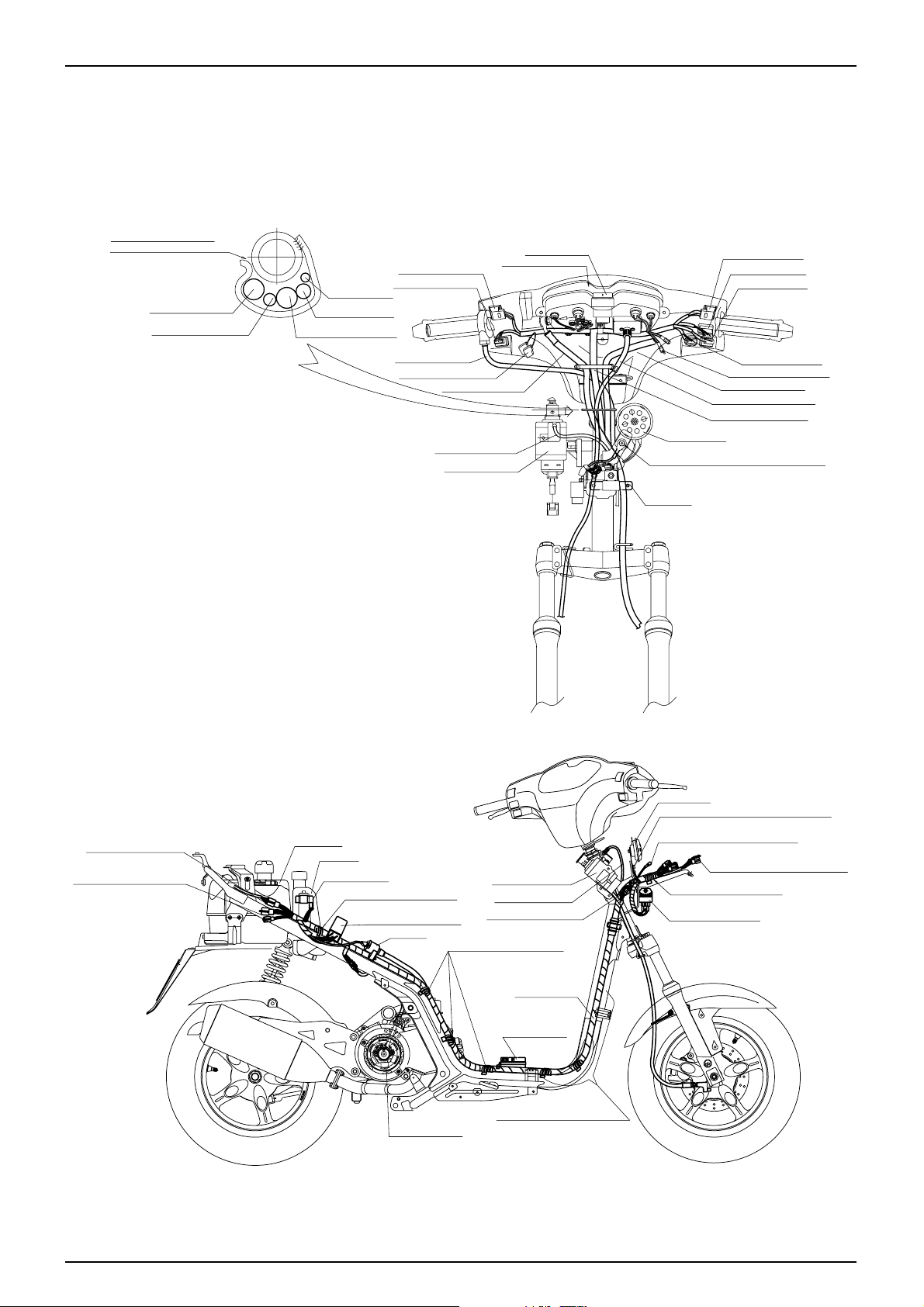
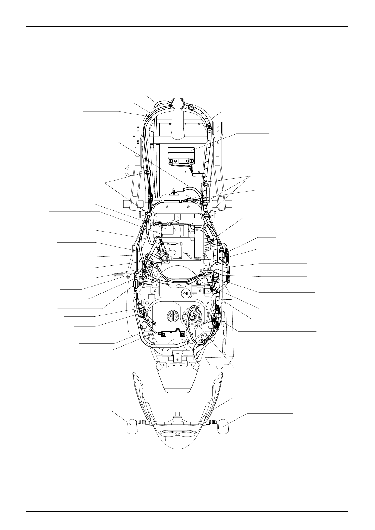
WIRING DIAGRAM
TUBELESS
TIRE
APPL.
KOREA
FUEL UNIT
CONNECTING COUPLER
R/L TAIL STOP RR. WINKER
AUTO BY STARTER 5W 6.7
Ω
OIL TANK
FUEL TANK
WIRE HARNESS
A.C.GENERATOR
THIS SECTION SHOULD NOT
BE PROJECTED THAN THE FRONT
OF THE FRAME AND NOT HAVE ANY
LOOSENESS.
BATTERY ASS'Y
ROLL THE HES. CLAMP
WITH THE CORD SECURELY.
I/G COIL
ROLL THE HES. CLAMP
WITH THE CORD SECURELY.
SEAT LOCK CABLE
COMBI LOCK S/W
CONNECTING COUPLER
COMBI LOCK S/W
REGULATE RECTIFIER
HEADLIGHT TIE-DOWN COUPLER
ROLL THE HES. CLAMP
WITH THE CORD SECURELY.
RESISTER CONNECTING COUPLER
HORN COMP
TIGHT AT THE SAME TIME WITH THE HORN.
FRAME EARTH
CDI UNIT ASS'Y
STARTER REALY ASS' Y
PRESS TO ATTACH THE
SEL. SECTION TO THE PIPE.
FR. BRAKE HOSE
SPEEDOMETER CORD
THROTTLE CABLE
LIGHTING S/W UNIT
WINKER REALY
DIMMER S/W UNIT
WINKER S/W UNIT
HORN S/W UNIT
HAZARD S/W UNIT
RR. STOP S/W CONNECTOR
SPEEDOMETER CABLE
SPEEDOMETER CORD
HORN COMP
FR. BRAKE HOSE
SEAT LOCK CABLE
COMBI LOCK S/W
RR.STOP S/W CONNECTOR
THROTTLE CABLE
FRAME EARTH
TIGHT AT THE SAME TIME WITH THE HORN.
RESISTOR
30W 5.6Ω
RR. BRAKE CABLE
SPEEDOMETER ASS'Y
STARTER S/W UNIT
RR. BRAKE CABLE
SPEEDOMETER CABLE
Page 22
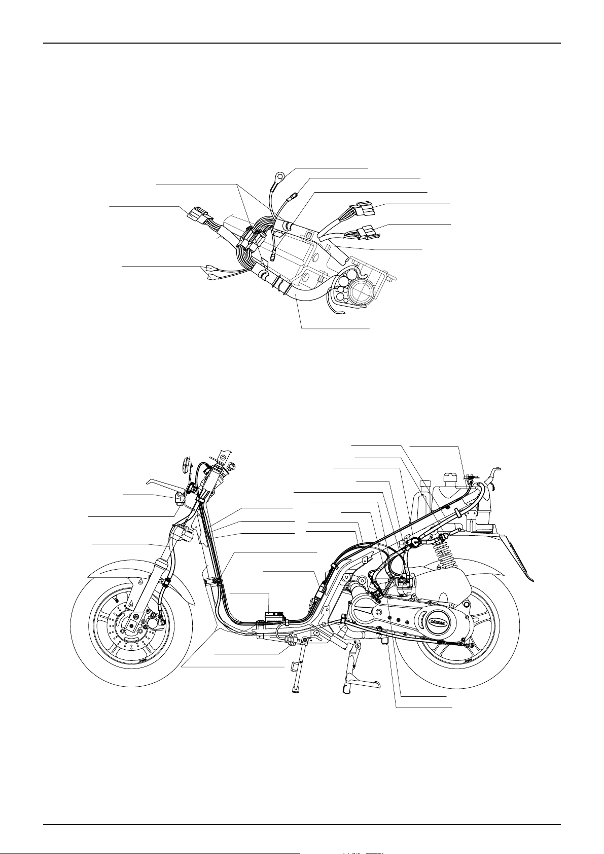
1-20
SERVICE INFORMATION
FRAME EARTH TERMINAL
HEADLIGHT
CONNECTING COUPLER
TIE-DOWN COUPLER
TIE-DOWN COUPLER
LIGHT COMP.
CONNECTING CONNECTOR
RESISTER CONNECTING CONNECTOR
AUTO BY STARTER S/W CORD 5W 6.7Ω
REGULATE RECTIFIER
COMBI LOCK S/W
WIRE HARNESS
SPEEDOMETER CORD
OIL PUMP CABLE
THROTTLE CABLE
AUTO BY STARTER CORD
THROTTLE CABLE
BATTERY ASS'Y
THIS SECTION SHOULD NOT
BE PROJECTED THAN THE FRONT
OF THE FRAME AND NOT HAVE ANY
LOOSENESS.
AUTO BY STARTER 5W 6.7Ω
FR. BRAKE HOSE
RESISTER
RR. BRAKE CABLE
ROLL THE HES. CLAMP
WITH THE CORD SECURELY.
ROLL THE HES. CLAMP
WITH THE CORD SECURELY.
SEAT LOCK CABLE
THROTTLE CABLE
RR. BRAKE CABLE
OIL PASS TUBE
SEAT LOCK CABLE
OIL TUBE
FUEL VENT TUBE
FUEL STRAINER
FUEL AUTO COCK ASS'Y
NEGATIVE PRESSURE TUBE
FUEL TUBE
RESISTER
II
VV
30W 5.6Ω
SIDE STAND SWITCH
Page 23
1-21
SERVICE INFORMATION
RR. BRAKE CABLE
THROTTLE CABLE
SEAT LOCK CABLE
HIGH TENSION CORD
STARTER MOTOR
OIL PUMP CABLE
THROTTLE CABLE
OIL PASS TUBE
OIL TUBE
AUTO BY STARTER CORD
FUEL TUBE
NEGATIVE PRESSURE TUBE
FUEL AUTO COCK ASS'Y
FUEL STRAINER
FUEL TANK
FUEL VENT TUBE
SEAT LOCK CABLE
LH. RR. WINKER LIGHT
RH. RR. WINKER LIGHT
TAIL LIGHT ASS'Y
FUEL UNIT
TAIL LIGHT CONNECTING CONNECTOR
CDI.UNIT ASS'Y
OIL LEVEL S/W
AUTO BY STARTER
CONNECTING COUPLER
ACG. CONNECTING COUPLER
ACG. CORD CLAMP
ROLL THE WHITE TAPE AREA OF ACG CORD
CLAMP IN THE POSITION OF THE CLAMP FIRMLY.
I/G COIL
I/G COIL
BATTERY ASS'Y
WIRE HARNESS
STARTER REALY ASS'Y
ENGINE EARTH
TIGHT AT THE SAME TIME
WITH THE STARTING MOTOR.
PRESS TO ATTACH THE
SEL. SECTION TO THE PIPE.
ROLL THE HES. CLAMP
WITH THE CORD SECURELY.
ROLL THE HES. CLAMP
WITH THE CORD SECURELY.
Page 24
MEMO
Page 25
2-1
2. INSPECTIONS/ADJUSTMENTS
SERVICE INFORMATION
WARNING
•The exhaust gas contains poisonous substance. Do not keep engine idling in a closed or poorly ventilated place for a
long period of time.
SPECIFICA TIONS
TORQUE VALUES
SPARK PLUG
1.4㎏f·m
CYLINDER HEAD COVER BOLTS
1.0㎏f·m
2
SERVICE INFORMATION 2-1
REGULAR INSPECTION SCHEDULE
2-2
FUEL LINE (FUEL TUBE)
2-3
FUEL LINE FOR CLOGGING
2-3
THROTTLE GRIP OPERATION
2-3
AIR CLEANER
2-4
SPARK PLUG
2-5
CYLINDER COMPRESSION PRESSURE
2-5
CARBURETOR IDLING
2-6
AIR SCREW ADJUSTMENT
2-6
BRAKE FLUID
2-6
BRAKE PAD/SHOE
2-7
BRAKE SYSTEM
2-7
HEADLIGHT ADJUSTMENT
2-8
SIDE STAND
2-8
SUSPENSION
2-9
BOLTS, NUTS, FASTENERS
2-9
WHEELS/TIRES
2-9
STEERING HEAD BEARING
2-10
BATTERY
2-10
ITEM STANDARD VALUE REFERANCE
THROTTLE GRIP FREE PLAY 2-6mm
SPARK PLUG B8HSA
SPARK PLUG GAP 0.6〜0.7mm
CARBURETOR IDLE SPEED 1,800±100rpm
CYLINDER COMPRESSION PRESSURE 10㎏f/㎠ - 600rpm
NOTE
•Stand the main stand prior to beginning work.
Page 26
2-2
INSPECTIONS/ADJUSTMENTS
REGULAR INSPECTION SCHEDULE
Carry out pre-operation check at each scheduled maintenance period based on the information described in the owner’s
manual.
I : INSPECT AND CLEAN, ADJUST, LUBRICATE OR REPLACE IF NECESSARY.
R : REPLACE L : LUBRICATE C : CLEAN
* If there are no appropriate type of tools and maintenance data available, or if you do not have mechanical technology
contact authorized maintenance shops, dealers or other designated repair shops for maintenance and inspections.
To ensure safety, inspections and maintenance of these parts must be carried out by authorized maintenance shops,
dealers or other designated repair shops.
NOTE
1. After the odometer reading exceeds 12,000km, repeat maintenance service at intervals indicated in the table.
2. After riding in areas with high humidity or pollution, carry out maintenance service more frequently.
3. Replace every 2 years. Proper technology is required for this job.
*
*
*
*
*
*
*
*
*
*
*
*
FUEL LINE(FUEL TUBE)
THROTTLE GRIP OPERATION
OIL PUMP, OIL LINE
CARBURETOR CHOKE
AIR CLEANER
SPARK PLUG
CARBON REMOVAL
CARBURETOR IDLE SPEED
TRANSMISSION OIL
BRAKE SHOE/PAD WEAR
BRAKE SYSTEM
BRAKE STOP SWITCH
HEADLIGHT ADJUSTMENT
CLUTCH SHOE WEAR
SUSPENSION
BOLTS, NUTS, FASTENERS
WHEELS/TIRES
STEERING HEAD BEARING
DRIVE BELT
WEIGHT ROLLER
SLIDE PIECE
NOTE 2
NOTE 3
I
I
I
I
I
I
I
I
C
I
I
I
I
I
I
I
I
I
I
I
I
I
I
I
I
C
I
I
I
I
I
I
I
I
I
I
I
I
I
I
I
I
I
I
C
I
I
R
I
I
I
I
I
I
I
I
I
I
Every 8,000㎞ : C
FREQUENCY
ODOMETER READING(NOTE 1)
61218
14812 REMARK
ITEM
x 1000Km
MONTH
Page 27
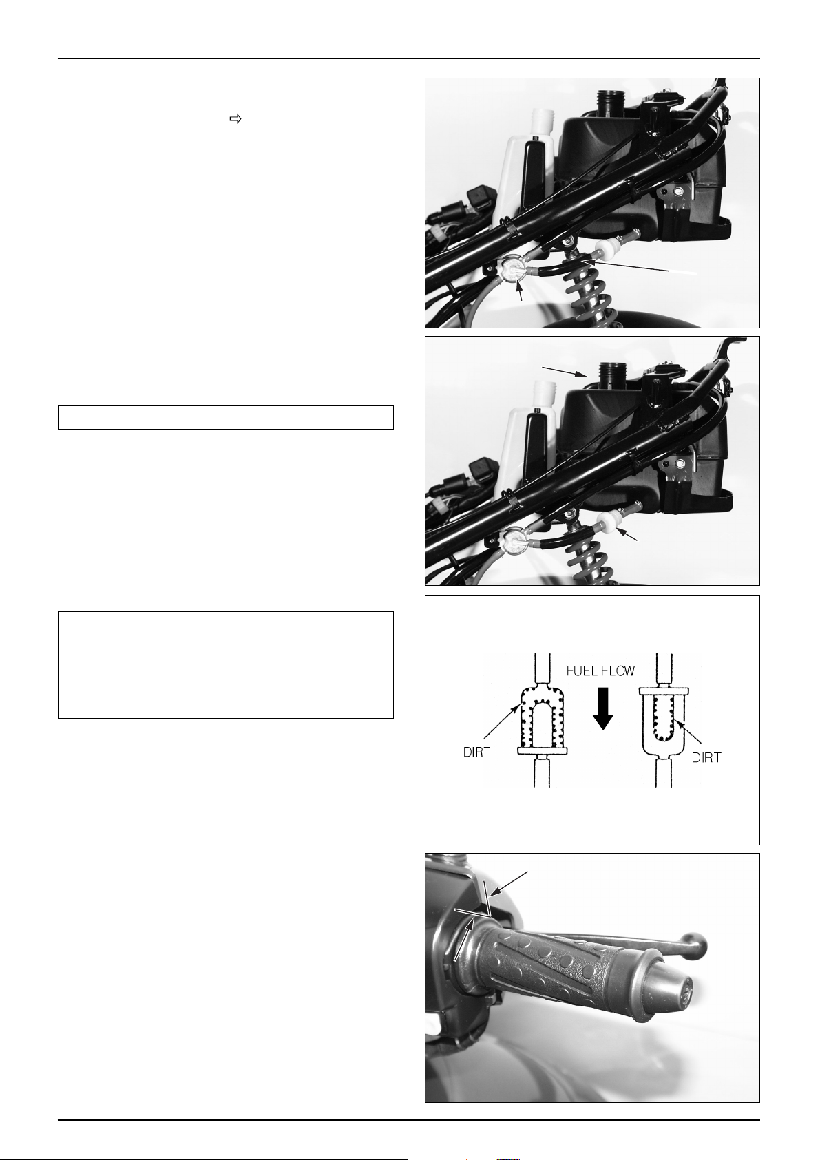
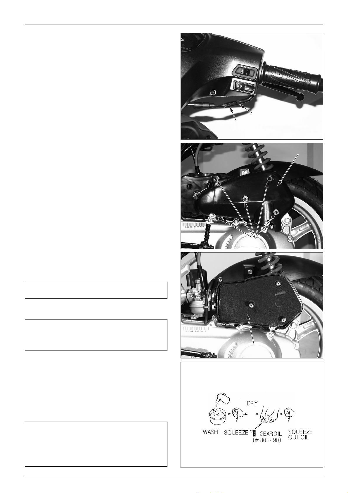
FUEL LINE(FUEL TUBE)
● Remove the luggage box.( 3-3)
● Check the fuel tube of the fuel auto cock connected to
the fuel tank and carburetor. If the fuel tube is cranked,
damaged or leaks, replace it.
FUEL LINE FOR CLOGGING
NOTE
•Refer to section 2 for fuel filter inspection.
● Check the fuel tank cap and/or fuel tank breather tube
for clogging.
● Visually inspect the fuel strainer for contamination.
Check the fuel flow with the fuel strainer installed and
with the strainer removed.
Replace the fuel strainer if it is excessively contaminated
or if the fuel flow is not smooth.
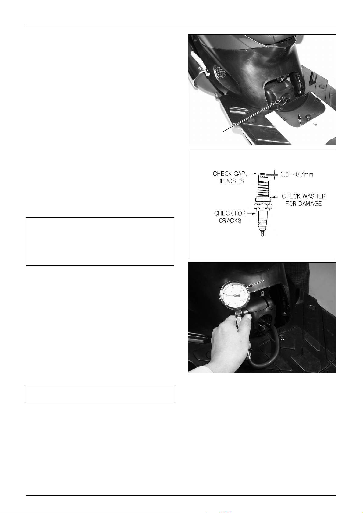
CAUTION
•Note the installation direction of the fuel strainer. Be
sure to install it as shown in the drawing, i.e., with
the cup facing down. Fuel flows even though the
strainer is installed upside down, but it contaminates
the inner wall of the strainer and prevents visual
inspection of the strainer .
● Remove the fuel valve lock nut and check the fuel
strainer screen for contamination. Tighten the lock nut
to the specified torque.
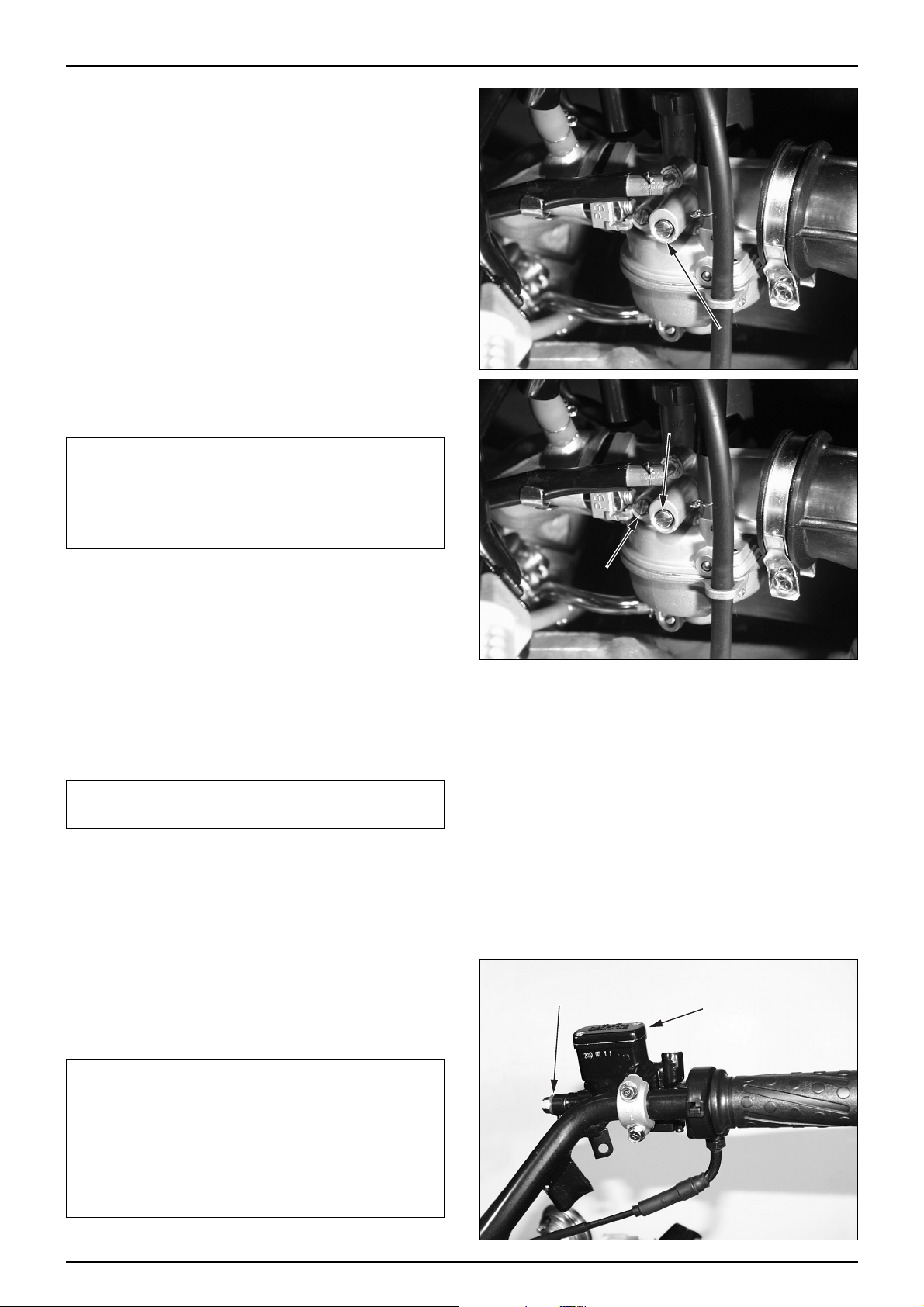
THROTTLE GRIP OPERA TION
● Check if the throttle grip operates smoothly in any
steering position
● If the throttle grip does not operate properly, lubricate
the throttle cable.
● If the throttle grip does not operate properly, check the
throttle cable for aging, damage or kinking.
● Check the throttle grip free play.
FREE PLAY : 2~6mm
2-3
INSPECTIONS/ADJUSTMENTS
FUEL TUBE
FUEL AUTO COCK
(Inner walls get
contaiminated,
making visual
inspection
difficult.)
FUEL TANK
FUEL STRAINER
Page 28
● For adjustment, loosen the lock nut and turn adjuster.
● After adjusting, tighten lock nut. After adjustment is
completed, recheck the throttle grip free play .
AIR CLEANER
● Loosen the 5 setting screw assembled to the air cleaner
case cover, and then remove the air cleaner case cover.
● Remove the air cleaner element.
● Wash away any accumulated dust or dirt, by gently
squeezing it in non flammable or high flash point
solvent.
WARNING
•Using gasoline or low flash point solvents for
cleaning parts may result in a fire or explosion.
CAUTION
•Cleaning the element with gasoline or any acid,
alkaline, or organic, volatile type oil may cause
improper ignition, deterioration of the element, or a
loosening of the element adhesive.
● Be sure to allow the element to dry thoroughly before
applying oil. Otherwise, the oil will be diluted by the
and the filtering ability of the filter will be much
less effective.
● Spread clean #80~90 gear oil on the element, rubbing
inthoroughly over the surface with both hands, and then
squeeze out any excess oil.
CAUTION
•Using air filter oil when riding in extremely dusty
conditions prevents premature engine wear due to
dust/dirt drawn into the engine. Apply air filter oil to
the entire surface of the element and rub it with both
hands to saturate the element with oil. Squeeze out
excess oil.
2-4
INSPECTIONS/ADJUSTMENTS
LOCK NUT
ADJUSTER
AIR CLEANER COVER
WASHER SCREW
AIR CLEANER ELEMENT
Page 29
SPARK PLUG
● Remove the plug maintenance cover.
● Remove the spark plug cap and disassemble the plug.
● Check the plug for damage, contamination or deposits.
● If the spark plugs are severely contaminated or
damaged, raplace with new ones. If the plugs can be
reused after removing only the carbon, use plug cleaner
and wire brush to clean the plugs.
● Always use a feeler gauge to check the gap.
SPARK PLUG GAP : 0.6~0.7mm
CAUTION
•Make sure there is no dirt or debris on the seat of the
spark plug hole before inserting the spark plug.
•To prevent damage to the cylinder head, hand-tighten
the spark plug before using a wrench to tighten to the
specified torque.(torque : 14kgf·m)
•Do not overtighten the spark plug.
CYLINDER COMPRESSION PRESSURE
● Start and warm up the engine.
● Remove the plug maintenance cover.
● Stop engine, and remove the spark plug cap and spark
plug.
● Install a compression gauge.
● Open the throttle completely, and crank the engine with
the starter motor until the gauge reading rising.
NOTE
•The maximum reading is usually reached within 4~7
seconds.
COMPRESSION PRESSURE : 13.8kg/cm
2
● If the pressure is low, check the following:
-Leakage from the cylinder head gasket
-Piston/cylinder worn
● If pressure is high, check the following:
-Carbon deposits on the piston head, and cylinder head.
TOOL : COMPRESSION GAUGE
2-5
INSPECTIONS/ADJUSTMENTS
SPARK PLUG CAP
PLUG MAINTENANCE COVER
COMPRESSION GAUGE
Page 30
CARBURETOR IDLING
● Stand the vehicle on the main stand.
● Heat the engine to make accurate idling inspection and
adjustment.
● Verify all engine adjustments satisfy specifications.
Make adjustments, if necessary .
● Turn the throttle stop screw and make adjustments to
prescribed idling speed.
AIR SCREW ADJUSTMENT
NOTE
•The air screw is factory pre-set. Adjustment is not
necessary unless the carburetor is overhauled or a
new air screw is installed.
•Tightening the air screw against its seat will damage
the seat.
● Turn the air screw clockwise until it seats lightly then
back it out to the specification given. This is an initial
setting prior to the final air screw adjustment.
● Rev the engine up slightly from the idle speed and
make sure that engine speed rises and returns smoothly.
● Adjust by turning the air screw in or out within a 1/4
turn if necessary. If the engine cannot be adjusted by
turning the air screw within a 1/4 turn, check for other
engine problems.
CAUTION
•Excessive air screw adjustment may cause the engine
sticking and deteriorate the starting performance.
BRAKE FLUID
● Remove the brake fluid cover.
● Check the oil level inside the front brake reservoir. If
the oil level is near the lower limit line, remove the
reservoir diaphragm and fill DOT 3 and DOT 4 brake
fluid to the top limit line.
● If the brake fluid reaches the lower limit line, check the
entire brake system for leaks.
CAUTION
•Brake fluid will damage painted, plastic or rubber
parts.
•Mixing incompatible fluids can impair braking
efficiency.
•Foreign materials can clog the system, causing a
reduction or complete loss of braking ability .
•A leak in the brake system can lead to reduced
braking effiency and possible loss of braking ability.
2-6
INSPECTIONS/ADJUSTMENTS
THROTTLE STOP SCREW
THROTTLE STOP SCREW
AIR SCREW
BRAKE HOSE BOLT
MASTER CYLINDER
Page 31

BRAKE PAD/SHOE
BRAKE P AD REPLACEMENT
● Check the brake pads for wear.
● If the red mark on the pad reaches the brake disc,
replace the pads.
NOTE
•Replace the brake pads in sets.
BRAKE SHOE REPLACEMENT
● If the arrow mark of the wear limit aligns with the ‘△’
mark when the rear brake lever is fully pressed, it
indicates the brake lining has reached the service limit.
Replace the brake shoes.
BRAKE SYSTEM
● Check the front brake hose for cracks or damage. If any
leaks are found, replace immediately .
● Check the brake rod for looseness or damage, and
replace it if necessary .
BRAKE LEVER FREE PLAY
● Check the free play after pulling the lever.
FRONT : 10~20mm
REAR : 10~20mm
2-7
INSPECTIONS/ADJUSTMENTS
RED MARK
MARK
BRAKE HOSE
BRAKE CALIPER
FREE PLAY
Page 32

REAR BRAKE FREE PLAY ADJUSTMENT
● Turn the adjuster nut to adjust the free play.
● After initial adjustment, check the operation of the rear
brake light switch. Make additional adjustments, if
necessary .
HEADLIGHT ADJUSTMENT
● Adjust the headlight beam level by operating the
adjusting screw located on the upper side of the front
fender.
NOTE
•Adjust the beam level according to local laws and
regulations.
•Improper beam level adjustment may blind
oncoming drivers, or may incorrectly light the road
ahead.
SIDE STAND
● Erect the main stand.
● Pull the lower end of the side stand, and see if it moves
freely .
● If the side stand does not move smoothly, apply grease
to the pivot area.
● If the side stand moves too freely, check the side stand
spring.
● Check the axial movement of the side stand.
● Check the side stand ignition cut-off switch :
-Put the side stand up.
-Start the engine.
-Lower the side stand. The engine should stop as you
put the side stand down.
● If there is a problem with the system, check the side
stand switch.
2-8
INSPECTIONS/ADJUSTMENTS
ADJUSTER NUT
ADJUSTER LEVER
SIDE STAND SPRING
Page 33

SUSPENSION
NOTE
•Do not ride motor cycle with an unsatisfactory
suspension. Loose or worn suspension parts will lead
to deterioration in the vehicle’s safety and operation
efficiency.
FRONT WHEEL
● Hold the brake lever, and compress the front cushion
up and down several times to check the operating
conditions.
● Check the front fork for oil leakage, parts damage or
looseness.
REAR WHEEL
● Compress the near cushion up and down several times
to check the operating conditions.
● Check the rear fork for oil leakage, parts damage or
looseness.
BOL TS, NUTS, FASTENERS
● Check all nuts and bolts of the frame during the regular
maintenance to check if they meet the prescribed
torque value.
● Check all pins, clips, hose clamps and cable stays.
WHEELS/TIRES
NOTE
•Check the tire pressure when the tires have been
cooled off. Check the tread (the part making contact
with the road surface) and side for wear, cracks or
damage. Replace damaged tires.
ST ANDARD PRESSURE
2-9
INSPECTIONS/ADJUSTMENTS
FRONT WHEEL
1.75(175)
2.00(200)
REAR WHEEL
2.00(200)
2.25(225)
ITEM
DRIVER ONLY
DRIVER AND A PASSENGER
f/ (kpa)
TIRE PRESSURE GAUGE
Page 34

● Check the tread depth at the tire center.
● If the tread depth has reached the service limit, replace
the tire.
SERVICE LIMIT :4.0mm
7.5mm
STEERING HEAD BEARING
NOTE
•Check the cable if it interferes with the handle
operation.
● Lift the front wheel and check if the handle moves right
and left smoothly. If the handles move heavily, check if
the cable or electric cord interferes with the handle. If
the hadle moves satisfactorily, adjust the steering head
bearing.
BATTERY
● Remove a tapping screw securing the battery cover
from the floor panel.
● Check if the terminal is loose.
● If the terminal is loose, check and clean the contacting
surface and then tighten it.
● Apply grease thinly after tightening.
● If the terminal is rusted, remove the battery, pour warm
water and clean with the wire brush.
- FULL CHARGING VOLT AGE: 13.0~13.2V
-
LOW CHARGING VOLTAGE: LESS THAN
12.3V
NOTE
•Check the charging condition using the voltmeter.
•Pay attention not to transform the battery terminal.
•Never remove the filler cap.
2-10
INSPECTIONS/ADJUSTMENTS
BATTERY COVER
TAPPING SCREW
DIGTAL TESTER
Page 35

3-1
3. EXTERNAL PARTS
SERVICE INFORMATION
NOTE
● This section describes external parts removal/installation.
● Do not apply unreasonable force when disassembling covers, to prevent possible damage.
● A muffler is hot. Do not service it immediately after the engine is stopped.
3
SERVICE INFORMATION 3-1
MAINTENANCE PRECEDURE
3-2
LUGGAGE BOX
3-3
PLUG MAINTENANCE
COVER/CENTER COVER
3-3
REAR CARRIER
3-3
BODY COVER
3-3
TAILLIGHT BASE
3-4
FLOOR SIDE COVER
3-4
FLOOR PANEL
3-4
ENGINE HANGER SIDE COVER
3-5
FRONT COVER 3-5
FRONT FENDER
3-5
INNER BOX
3-5
FRONT UNDER COVER
3-6
FRONT HANDLE COVER
3-6
REAR HANDLE COVER
3-6
MUFFLER
3-7
REAR FENDER
3-7
REAR WHEEL MUD GUARD
3-8
UNDER COVER
3-8
Page 36

3-2
EXTERNAL P ARTS
10
11
15
12
5
6
9713
8
1
4
3
2
14
MAINTENANCE PROCEDURE
NAMES OF FRAME COVERS
● This chart shows arrows connected in the order of disassembling covers.
① LUGGAGE BOX
②
PLUG MAINTENANCE
COVER
③ CENTER COVER
④ REAR CARRIER
⑤ BODY COVER
⑥ TAILLIGHT BASE
⑦ FLOOR SIDE COVER
⑧ FLOOR PANEL
⑨ ENGINE HANGER
SIDE COVER
⑩ FRONT COVER
⑪ FRONT FENDER
⑫ INNER BOX
⑬ FRONT UNDER
COVER
⑭ FRONT HANDLE
COVER
⑮ REAR HANDLE
COVER
Page 37

3-3
EXTERNAL P ARTS
LUGGAGE BOX
● Release the seat lock using the main key to open the
seat.
● Loosen 4 washer bolts and 2 flange bolts.
● Remove the oil tank cap and the fuel tank cap.
NOTE
•Luggage box can be removed with the seat.
● Remove the luggage box.
● Install in the reverse order of removal.
CAUTION
•Install the oil tank cap and the fuel tank cap
temporarily to prevent the foreign material from
entering after removing the luggage box.
PLUG MAINTENANCE COVER/CENTER COVER
● Release the seat lock using the main key to open the
seat.
● Loosen the washer bolt securing the luggage box.
● Loosen the special screw to remove the plug
maintenance cover .
● Loosen 2 tapping screw securing the floor panel.
● Loosen 2 special screw (R/L) securing the body cover.
● Remove the center cover.
CAUTION
•If removal is difficult, recheck each connection and
then try removing again.
● Install in the reverse order of removal.
REAR CARRIER
● Loosen 3 special bolts securing the top of the body
cover.
● Remove the rear carrier.
● Install in the reverse order of removal.
CAUTION
•Pay attention not to break of damage the rear carrier
when installing or removing.
BODY COVER
● Remove the luggage box. ( 3-3)
● Remove the center cover. (
3-3)
● Remove the rear carrier. (
3-3)
● Loosen 2 special screw (R/L) securing the frame body.
● Loosen 2 body cover clip (R/L) securing the tail light
base.
● Remove the body cover.
● Install in the reverse order of removal.
WASHER BOLT
SPECIAL SCREW
FLANGE BOLT
TAPPING SCREW
SPECIAL SCREW
SPECIAL BOLT
BODY COVER CLIP
SPECIAL SCREW
Page 38

3-4
EXTERNAL P ARTS
TAILLIGHT BASE
● Remove the luggage box. ( 3-3)
● Remove the center cover. (
3-3)
● Remove the rear carrier. (
3-3)
● Remove the body cover. (
3-3)
● Loosen 2 washer bolt securing the frame.
● Loosen 2 body cover clip securing the rear fender.
● Disconnect the taillight wiring.
● Remove the taillight base.
● Install in the reverse order of removal.
FLOOR SIDE COVER
● Loosen the 2 washer screw located in the side of the
R,L floor side cover .
● Loosen the tapping screw (R/L) securing the lower and
rear end of the floor panel.
● Pull the front part of the floor side cover to remove the
floor panel.
● Remove the floor side cover.
● Install in the reverse order of removal.
FLOOR PANEL
● Remove the plug maintenance cover. ( 3-3 )
● Remove the center cover. (
3-3)
● Loosen the tapping screw securing the battery cover to
remove the battery cover .
● Disconnect the battery wiring to remove the battery.
● Remove the floor side cover.
● Remove the floor panel cap A and B.
● Loosen the 4 washer bolts securing the floor panel.
● Remove the floor panel from the connecting groove of
the inner box by lifting the rear part of the panel
slightly .
● Draw the floor panel moving it to the right and left to
remove it.
● Install in the reverse order of removal.
WASHER BOLT
TAILLIGHT WIRING
BODY COVER CLIP
WASHER SCREW
FLOOR PANEL CAP
WASHER BOLT
Page 39

3-5
EXTERNAL P ARTS
ENGINE HANGER SIDE COVER
● Loosen the 2 washer screw securing the engine hanger
side cover.
● Install in the reverse order of removal.
FRONT COVER
● Loosen the upper cover set screws (R/L) securing the
inner box.
● Loosen the upper cover set screws (R/L) securing the
front under cover .
● Loosen the special bolt securing the front of the front
cover.
● Draw the upper part of the front cover to remove it.
● Disconnect the head light wiring and remove the front
cover.
● Install in the reverse order of removal.
NOTE
•Check for proper alignment of the connection (hook)
before performing installation.
FRONT FENDER
● Loosen the flange bolts (R/L) securing the front fork.
● Remove the front fender.
● Install in the reverse order of removal.
INNER BOX
● Remove the center cover. ( 3-3)
● Remove the floor side cover. (
3-4)
● Remove the floor panel. (
3-4)
● Remove the front cover. (
3-5)
● Loosen the tapping screws (R/L) securing the front
under cover.
● Loosen the special bolts securing the right and left
sides of the front cover .
● Turn the main key cover slightly to release the locking
and remove the cover .
● Remove the cover set screw securing the back holder,
take off the joint part of the front under cover and
remove the inner box.
● Install in the reverse order of removal.
WASHER SCREW
SPECIAL BOLT
SETTING
SCREW
SPECIAL SCREW
TAPPING
SCREW
SETTING SCREW
SPECIAL SCREW
Page 40

3-6
EXTERNAL P ARTS
FRONT UNDER COVER
● Remove the front cover. ( 3-5)
● Remove the inner box. (
3-5)
● Remove the front fender. (
3-5)
● Remove the front wheel. (
10-5 )
● Loosen the flange bolts securing the lower end of the
inner box.
● Remove the front under cover.
● Install in the reverse order of removal.
NOTE
•Pay attention not to turn over the vehicle.
FRONT HANDLE COVER
● Remove the back mirror.
● Remove the master cylinder seal.
● Loosen the 3 tapping screws securing the rear handle
cover.
● Remove the front handle cover while pull the cover to
the front slightly .
● Install in the reverse order of removal.
REAR HANDLE COVER
● Remove the back mirror.
● Remove the front cover. (
3-5)
● Remove the front handle cover. (
3-6)
● Remove the speedometer cable from the meter.
● Loosen the 4 tapping screws securing the steering
handle comp.
● Disconnect the right and left switch wiring.
● Remove the speedometer and rear handle cover from
the steering handle.
● Disconnect the right and left switch.
● Loosen the 3 tapping screws securing the speedometer
and the rear handle cover .
● Remove the rear handle cover.
● Install in the reverse order of removal.
NOTE
•Check each switch for proper operation after
installation.
•Wires and cables must be connected properly.
FLANGE
BOLT
FLANGE
BOLT
TAPPING
SCREW
TAPPING
SCREW
TAPPING
SCREW
TAPPING
SCREW
MASTER
CYLINDER
TAPPING
SCREW
TAPPING
SCREW
SPEEDOMETER
CABLE
Page 41

3-7
EXTERNAL P ARTS
MUFFLER
● Loosen the 3 flange nuts securing the EX pipe comp.
● Loosen the 2 flange bolts securing the R. crankcase.
● Loosen the 2 flange bolts securing the rear wheel mud
guard.
● Remove the EX muffler comp.
WARNING
•Never perform the maintenance of the muffler right
after stopping the vehicle because the muffler is
extremely hot
EX. PIPE REMOV AL
● Loosen the 2 flange bolts securing the cylinder comp.
● Remove the EX pipe by drawing it to the ground
direction.
INST ALLATION
● Install the 2 flange bolts after securing the EX pipe
with the stud bolt of the cylinder comp.
● Install the gasket on the EX muffler, connect the EX
pipe and install the 2 flange nuts temporarily.
● Install the 2 flange bolts on the R. crankcase
temporarily .
● Tighten the 3 flange nuts to install the EX muffler and
the EX pipe.
● Install the 2 flange bolts on the rear wheel mud guard.
● Tighten the muffler securing 2 flange bolts to install the
R. crankcase.
● Tightening torque of the R. crankcase.
TORQUE : 3.3kgf
··
m
CAUTION
•When installing the gasket, replace it with the new
one.
•Check to see if there is any evacuation after installing
the muffler .
REAR FENDER
● Luggage box. ( 3-3)
● Plug maintenance cover. (
3-3)
● Center cover. (
3-3)
● Rear carrier. (
3-3)
● Body cover. (
3-3)
● Taillight base. (
3-4)
● Remove the 2 washer bolts securing the fuel tank
support stay .
● Draw the rear part of the rear fender from the bracket in
the frame.
●
Loosen the rear cushion under bolt, remove the rear fender.
CAUTION
•If removal is difficult, recheck each connection and
try removing again.
● Install in the reverse order of removal.
FLANGE BOLT
FLANGE BOLT
FLANGE NUT
FLANGE NUT
WASHER
BOLT
WASHER
BOLT
Page 42

REAR WHEEL MED GUARD
● Loosen the 2 flange bolts securing the EX muffler.
● Loosen the flange bolt securing the air cleaner.
● Loosen the flange bolt securing the inlet pipe.
● Remove the rear wheel mud guard.
● Install in the reverse order of removal.
NOTE
•Never perform the maintenance of the muffler right
after stopping the vehicle because the muffler is
extremely hot.
UNDER COVER
● Remove the floor side cover. ( 3-4)
● Remove the engine hanger side cover. (
3-5)
● Loosen the 2 R/L setting screws securing the frame.
● Remove the under cover.
● Install in the reverse order of removal.
EXTERNAL P ARTS
3-8
FLANGE BOLT
REAR WHEEL MUD GUARD
UNDER COVER
SETTING SCREW
Page 43

4-1
4. LUBRICATION SYSTEM
SERVICE INFORMATION
CAUTION
·Remove air from oil tube and oil pump if the oil tube is taken of f or if air enters the oil tube.
● If the oil tube is disassembled, remove the air in the oil pass tube.
● Maintenanace on the oil pump is done without the engine being removed from the vehicle.
● When disassembling the oil pump, do not allow foreign substances from entering the engine or oil pump.
● Do not disassemble the oil pump assembly.
● If the oil tube is disassembled, place a tube clip or band on the oil tube to prevent oil from leaking out.
TROUBLESHOOTING
Overheating or engine clogging
● Faulty adjustment of oil pump(insufficient amount pumped).
● Bad quality of engine oil.
● Engine oil not being injected or blocked, bent strainer screen or oil tube.
● Entering of air in oil tube system.
● Faulty oil pump.
● Engine oil not being supplied from oil tank.
-Blocked oil tank cap air hole
-Blocked oil strainer screen
Excess exhaust smoke, accumulation of carbon on spark plug
● Faulty adjustment of oil pump(over-pumped amount).
● Bad quality of engine oil.
4
SERVICE INFORMATION 4-1
TROUBLESHOOTING
4-1
OIL SYSTEM DRAWING
4-2
OIL PUMP DISASSEMBLY/
ASSEMBLY
4-3
OIL PUMP INSPECTION/
ADJUSTMENT
4-3
OIL PUMP BLEEDING 4-4
ENGINE OIL LEVEL INSPECTION
4-6
TRANSMISSION OIL INSPECTION
4-7
OIL TANK DISASSEMBLY
4-8
LUBRICATION POINTS
4-9
Page 44

4-2
LUBRICA TION SYSTEM
OIL SYSTEM DRA WING
OILTANK
OILTUBE
CARBURETOR
OILPASSTUBE
OILPUMP
OILPUMPCONTROLCABLE
OILPUMPANCHORPLATE
Page 45

OIL PUMP DISASSEMBLY/ASSEMBL Y
● Remove the luggage box. ( 3-3)
● Remove the rear wheel mud guard. (
3-8 )
● Remove the air cleaner. (
5-4 )
● Remove the carburetor. (
5-4 )
● Loosen the oil pump cable stay bolt to remove the oil
pump anchor plate.
● Disconnect the oil control cable from the oil pump.
● Remove the inlet pipe. (
5-9 )
● Remove the oil tube in the oil pump side.
● Remove the oil pass tube.
● Loosen the flange bolt securing the oil pump.
● Remove the setting plate of the oil pump.
● Remove the oil pump.
● Install in the reverse order of removal.
CAUTION
•When assembling/disassembling the oil pump, do
not allow foreign substances from entering the
engine and oil tube by cleaning around the oil pump.
•If the air enters into the oil line, it may cause faulty
lubrication or engine sticking. Always remove the air
in the oil line after maintenance.
• Pay attention not to damage the O-ring when
assembling the oil pump.
OIL PUMP INSPECTION/ADJUSTMENT
● Remove the oil pump.
● Rotate the shaft and check for proper rotation.
● Check the gear for wear, damage and leak of each seal.
● If the oil comes out from the outlet of the oil pump
after connecting the oil tube (which is connecting
between the tank and the oil pump) to the inlet and
rotating the shaft in the driving direction, consider the
oil pump is in good condition.
4-3
LUBRICATION SYSTEM
FLANGE BOLT
OIL ANCHOR PLATE
INLET PIPE
OIL PUMP CONTROL CABLE
OIL PASS TUBE
OIL TUBE
SETTING PLATE
OIL PUMP
Page 46

ADJUSTMENT
CAUTION
•Perform after inspection and adjustment of throttle
cable.
● Check to see if the matching mark of the oil pump
body and control lever are aligned in a state where
the throttle grip is completely rotated.
● Adjustment is performed by loosening the oil pump
control cable lock nut and turning the control nut.
● While the engine is running, slightly open the throttle
and check to see if the control lever operates together
with the increase in engine rpms.
CAUTION
•Do not adjust the control lever matching mark to the
closed side of the oil pump body matching mark. If
this is done, the amount of pumped oil is reduced,
negatively affecting the engine.
•Make sure that the open axis stays within an 1mm
sphere.
● The following occurs when the oil pump is adjusted
incorrectly .
-When the oil pump lever is excessively opened :
Emitting of white exhaust gas or starting problems.
-When the oil pump lever is insufficiently opened :
Clogging of engine.
NOTE
•If the oil pump cable stay bolt is removed, apply the
screw locking compound to the bolt thread.
OIL PUMP BLEEDING
CAUTION
•Air infiltration in the oil pass may cause the engine
sticking. Always remove the air in the oil pass after
maintenance.
•When disassembling the oil tube, air can be enter
into the oil tube and the oil pump because of the oil
leaking in the oil tube. Remove the air completely.
•Do not allow foreign substances from entering the oil
pass.
4-4
LUBRICA TION SYSTEM
CONTROL
LEVER
CABLE STAY NUT
OIL PUMP CABLE
STAY NUT
CONTROL
LEVER
Page 47

OIL PUMP/OIL TUBE
● Fill the oil tank with engine oil.
● Cap around the oil pump and the carburetor with dry
cloth.
● Locate the end of the oil tube in the level lower than the
oil tank and drain the oil to bleed the air .
● Install the oil tube in the oil pump.
●Incline the oil pump to locate the oil pump shaft at the
angle of 45。from the “▲ ”mark with oil tube
connected.
●In this state, locate the oil pump in the level lower
than the oil tank and drain the oil to bleed the air .
●Install the oil pump shaft in the oil pump after
completing the bleeding.
●Install the oil pump in the crankcase.
OIL P ASS TUBE
● Bend the oil pass tube in the “U” shape, keep the two
ends parallel with each other and fill the oil pass tube
with the oil.
4-5
LUBRICATION SYSTEM
OIL TUBE
Page 48

● Connect the oil pump and then the carburetor quickly
with the both ends of the tube pressed to avoid the air
from entering.
NOTE
•Make sure that the tubes are arranged correctly.
● Start the engine.
NOTE
•Do not start the engine in the poorly-ventilated area.
● Open the oil pump control level fully and idle for
2minutes to bleed the air remained in the oil pass tube
with the oil drained from the oil pump.
NOTE
•Do not increase the engine RPM more than required.
● Connect the oil control cable.
NOTE
•Adjust the oil pump if the adjustment nut of the oil
comtrol lever is loose.
ENGINE OIL LEVEL INSPECTION
● Check the engine oil level if the pilot lamp blinks when
the main switch is turned on.
LOW OIL WARNING LIGHT BLINKING LEVEL : 0.3
4-6
LUBRICA TION SYSTEM
CONTROLLEVER
OILPASSTUBE
OIL WARNING LIGHT
Page 49

● Remove the oil tank cap and fill the oil tank with oil to
the level of the projected portion
RECOMMENDED OIL : ULTRA 2 SUPER OIL
● Reinstall the oil tank cap and check to see if the pilot
lamp turns off when the main swich is turned on.
TRANSMISSION OIL INSPECTION
● Check the body and the connection of each engine
component for any leak.
● Remove the oil check bolt and check to see if the oil
overflows from the oil check hole.
● If only the small amount of oil overflows, fill the
recommended transmission oil through the oil filler
hole gradually .
NOTE
•Oil level inspection must be performed in the flat
ground with the vehicle being straight by raising the
main stand.
RECOMMENDED OIL : SAE 80W / 90
● Tighten the oil level check bolt.
TIGHTENING TORQUE : 1.3kgf·m
● Start the engine and check for leak.
4-7
LUBRICATION SYSTEM
OIL CHECK
BOLT
Page 50

OIL TANK DISASSEMBL Y
● Remove the luggage box.
● Remove the oil level switch connector.
● Remove the tube in the oil pump.
● Install the tube clip or the valve in the oil tube to avoid
the oil from leaking.
● Remove the flange bolt securing the oil tank and press
the left and lower rear fender to remove the oil tank.
● Drain the oil from the oil tank.
● Remove the oil level switch.
● Remove the oil tube.
● Remove the oil strainer.
INSPECTION
● Check the oil level switch and the oil tube for proper
installation.
● Install in the reverse order of removal.
CAUTION
•If the oil enters into the oil pass, it may cause
abnormal lubrication or engine sticking. Always
remove the air in the oil pass after maintenance.
•Make sure that the oil tube is connected properly.
•Drain the oil in the clean container.
•Install the oil strainer after cleaning it.
4-8
LUBRICA TION SYSTEM
FLANGE BOLT
OIL TANK
OIL LEVEL SWITCH CONNECTOR
OIL LEVEL SWITCH
Page 51

LUBRICATION POINTS
LUBRICA TIAON SYSTEM
THROTTLEGRIP
STEERINGBEARING
WHEELBEARING
SPEEDOMETERGEARBOX
SIDESTANDPIVOT
WHEELBEARING
THROTTLESPEEDOMETER
BRAKEHOSE
GREASE
GREASE
GREASE
GREASE
GREASE
GREASE
OIL
4-9
Page 52

FUEL SYSTEM
5-0
CARBURETOR
FUELSTRAINER
FUELTUBE
AUTOCOCK
FUELTANK
Page 53

SERVICE INFORMATION
GENERAL SAFETY
WARNING
● Gasoline is extremely flammable. Avoid fire in the work place, also paying particular attention to sparks. Furthermore,
the evaporated (gasified) gasoline is highly explosive. Work in a well-ventilated areas.
● Exhaust gas contains poisonous substance. Do not keep engine running for a long period of time in a closed, or poorly
ventilated area.
CAUTION
● Do not excessively bend or twist cable. Distorted or damaged cable may lead to mechanical malfunctions.
● Pay particular attention to the position of O-ring. Replace with new ones when disassembled.
● If it is desired to store a vehicle for a period longer than 1 month, drain gasoline out of the carburetor float chamber.
Gasoline left in the float chamber will be deteriorated causing the slow jet to be clogged with deposits, and idling may
become unstable.
SPECIFICA TIONS
FUEL T ANK CAPACITY : 5.8ℓ
RESER VE FUEL CAPACITY : 1.7ℓ
CARBURETOR
TOOL
FLOAT LEVEL GAUGE
5-1
5. FUEL SYSTEM
5
SERVICE INFORMATION 5-1
TROUBLESHOOTING
5-2
FUEL TANK
5-3
AIR CLEANER REMOVAL
5-4
AIR CLEANER ELEMENT
DISASSEMBLY 5-4
ITEM
TYPE/THROTTLE BORE
VENTURI DIAMETER
MAIN JET No.
SLOW JET No.
STANDARD
PB11P
16mm OR EQUIVALENT
#75
#38
ITEM
PILOT SCREW OPENING
FLOAT LEVEL
IDLING SPEED
THROTTLE GRIP FREE PLAY
STANDARD
1, 1/4 RETURNS
8.0mm
1,800±100rpm
2-6mm
CARBURETOR REMOVAL/
INSTALLATION
5-4
CARBURETOR INSPECTION
5-6
THROTTLE V ALVE
5-7
FUEL AUTO COCK
5-8
INLET PIPE REED VALVE 5-9
Page 54

5-2
FUEL SYSTEM
TROUBLESHOOTING
The vehicle does not start.
● No gasoline in fuel tank.
● Fuel is not coming out of carburetor.
● Too much fuel is flowing into cylinder.
● No spark emitted from spark plug.
● Air cleaner is blocked.
● Suction system is experiencing secondary intake of air.
● Using low quality gasoline.
● Starter is damaged.
● Throttle cable is working improperly.
● Fuel tank is functioning improperly.
Idle is unstable and engine turns off after starting.
● Starter is damaged.
● Ignition system is damaged.
● Using low qualty gasoline.
● Suction system is experiencing secondary intake of air.
● Idle is adjusted improperly.
● Air screw is adjusted improperly.
● Compression pressure is low.
● Air/Fuel mixture is either too lean or rich.
● Carburetor is blocked.
Mis-firing occurs when driving at high speeds.
● Ignition system is damaged.
● Mixture is too lean.
Back firing
● Ignition system is damaged.
● Mixture is too lean.
Insufficient power and high fuel consumption.
● Air cleaner is blocked.
● Ignition system is damaged.
● Mixture is too rich.
Air/Fuel mixture is extremely lean
● Fuel jet is blocked.
● Float valve is damaged.
● Oil level is low.
● Bad ventilation of air in tank cap.
● Fuel strainer screen is blocked.
● Fuel tube is bent, creased or blocked.
● Suction system is receiving secondary suction of air.
Air/Fuel mixture is extremely rich.
● Air jet is blocked.
● Float valve is damaged.
● Oil level is too high.
● Starter is damaged.
● Air cleaner is blocked.
Page 55

5-3
FUEL SYSTEM
FUEL TANK
REMOV AL
WARNING
•Gasoline is extremely flammable. Avoid fire during
work, and pay particular attention to electric sparks.
Furthemore, the evaporated (gasified) gasoline is
highly explosive. Work in a well-ventilated areas.
● Remove the following parts.
- Luggage box. (
3-3)
- Plug maintenance cover.(
3-3 )
- Center cover. (
3-3)
- Rear carrier. (
3-3)
- Body cover. (
3-3)
- Taillight base. (
3-4)
● Remove the fuel tube from the fuel auto cock.
NOTE
•Use the tube clip or the cap to prevent the gasoline
from leaking.
● Remove the fuel unit wire coupler.
● Remove the rear fender. ( 3-7)
● Loosen the 2 flange bolts and remove the seat catch.
● Loosen the 2 flange bolts and remove the fuel tank
support stay .
● Loosen the 2 flange bolts and remove the fuel tank.
INST ALLATION
Install in the reverse order of removal.
NOTE
• Check for gasoline leakage.
•“Gasoline”mark is on the fuel tank cap.
• Check this mark when filling gasoline.
AUTO COCK
FUEL TUBE A
SEAT CATCH
FUEL TUBE B
FUEL STRAINER
FLANGE
BOLT
FUEL UNIT
FLANGE
BOLT
FUEL TANK SUPPORT STAY
Page 56

5-4
FUEL SYSTEM
AIR CLEANER REMOVAL
● Loosen the air cleaner connecting bend screw pin.
● Loosen the 2 bottom air cleaner washer bolts.
● Loosen the top rear fender flange bolt.
● Remove the air cleaner from the carburetor.
● Install in the reverse order of removal.
AIR CLEANER ELEMENT DISASSEMBL Y
● Loosen the 5 air cleaner cover washer screws.
● Remove the air cleaner cover.
● Remove the air cleaner element.
● Install in the reverse order of disassembly.
CARBURETOR REMOV AL/INSTALLA TION
NOTE
•Keepthefireaway.
•Open the drain screw to drain the gasoline in the
carburetor chamber .
● Remove the luggage box. (
3-3)
● Remove the plug maintenance cover. (
3-3)
● Remove the center cover. (
3-3)
● Remove the air cleaner. (
5-4)
● Remove the wiring coupler of the auto by starter.
● Remove the oil pass tube.
● Remove the throttle valve set.
● Remove the 2 flange bolts securing the inlet pipe.
● Remove the carburetor insulator.
● Remove the carburetor.
● Install in the reverse order of removal.
NOTE
•Install the carburetor after aligning the throttle valve
cutaway and the throttle stop screw .
•Tighten the top set correctly so that it is not released.
FLANGE BOLT
WASHER
SCREW
WASHER BOLT
AIR CLEANER ELEMENT
CONNECTING
BEND
CARBURETOR
INSULATOR
CARBURETOR
FLANGE BOLT
CARBURETOR
INSULATOR
Page 57

5-5
FUEL SYSTEM
WASHERSCREW
AUTOBYSTARTER
SETPLATE
AIRSCREW
THROTTLE
STOP
SCREW
GASKET
O-RING
FLOATPIN
FLOAT
FLOAT
VALVE
FLOAT
CHAMBER
AUTOBY
STARTERCOVER
AUTOBY
STARTER
CARBURETOR DISASSEMBLY/ASSEMBL Y
● Remove the auto by starter cover.
● Loosen the 2 washer screws
● Remove the auto by starter set plate.
● Remove the auto by starter.
● Remove the auto by starter O-ring.
● Assemble in the reverse order of disassembly.
NOTE
•Install the auto by starter in the carburetor body after
applying grease to the starter O-ring and then tighten
firmly with set plate piece.
FLOAT CHAMBER/FLOAT/JET
DISASSEMBLY/ASSEMBLY
● Loosen the 2 float chamber screws.
INSPECTION
● Check the float valves and seats for cracks or damage.
● Check the float valve operation.
● Check the float valve level.
FLOA T LEVEL: 8mm
● Remove the main jet, needle jet holder, and needle jet,
and remove the slow jet.
● Remove the air screw, spring, washer, O-ring.
● Remove the throttle stop screw, spring, O-ring.
O-RING
SLOW JET
WASHER
FLOAT LEVEL
GAUGE
THROTTLE
STOP SCREW
AIR SCREW
MAIN JET
FLOAT
FLOAT VALVE
Page 58

5-6
FUEL SYSTEM
CARBURETOR CLEANING
● After removing all parts, blow open air and fuel
passages in the carburetor body with compressed air .
CAUTION
•Cleaning the air and fuel passages with a piece of
wire will damage the carburetor body or fuel pump.
● Assemble in the reverse order of disassembly.
CAUTION
•Tightening air screw against its seat will damage the
seat.
NOTE
•Be sure to install the needle jet with the smaller hole
toward the float chamber .
•Install the air screw and its O-ring and washer in the
order as shown in the drawing. If the air screw and
carburetor body are replaced with the new ones,
adjustment is necessary .
CARBURETOR INSPECTION
● Connect an ohmmeter to the auto bystarter wire
connector terminals and measure the resistance. If the
resistance is greatly out of specification, it indicates a
faulty PTC in the auto bystarter. Replace the auto
bystarter.
NOTE
•The auto by starter might be normal if the resistance
is only slightly out of specification. However , be sure
to check all related parts for trouble.
•Refer to the Model Specific manual for specified
resistance.
● Remove the carburetor and let it cool down for 30
minutes. Insert a vinyl tube into the fuel enrichening
circuit and blow into the tube.
● Air should flow into the circuit.
● If air does not flow into the circuit, replace the auto
bystarter.
AIR GUN
Page 59

5-7
FUEL SYSTEM
● Connect the battery to the auto bystarter terminals and
wait for 5 minutes.
● Insert a vinyl tube into the fuel enrichening circuit and
blow into the tube.
● Air should not flow into the circuit. If air flows into the
circuit, replace the auto bystarter .
● Check the resister if the auto bystarter is normal but
engine is still hard to start.
● If there is a broken wire in the resister, current will not
flow to the PTC and the auto bystarter will not operate.
● If there is a shorted wire in the resister, current of a
higher voltage than specified will reach the PTC. This
will cause the fuel enrichening circuit to close too soon,
and starting will be difficult.
THROTTLE VAL VE
DISASSEMBLY
● Remove the throttle valve.
● Remove the throttle cable.
● Remove the throttle valve spring.
● Remove the needle clip.
● Remove the seal cap.
● Remove the clip.
● Remove the jet needle.
ASSEMBLY
● Install the jet needle into the throttle valve and secure
with the retainer .
● Route the throttle cable through the spring and
compress the spring fully .
● Attach the throttle cable end to the bottom of the
throttle valve and thread the throttle cable through the
slot in the valve.
● Align the cutout in the throttle valve with the throttle
stop screw on the carburetor body and install the valve
on the carburetor .
NOTE
•Be sure that the throttle valve cutaway is toward the
air cleaner case side as it determines the volume of
air for fuel mixture.
● Operate the valve after installing the throttle valve.
Page 60

5-8
FUEL SYSTEM
FUEL AUTO COCK
REMOV AL/INSTALLATION
● Remove the luggage box. (⇨3-3)
● Remove the plug maintenance cover. (⇨3-3)
● Remove the center cover. (⇨3-3)
● Remove the rear carrier. (⇨3-3)
● Remove the body cover. (⇨3-3)
● Remove the fuel tube A, B connected to the carburetor.
● Remove the inlet pipe negative pressure tube.
● Remove the fuel tube A, B connected to the fuel tank.
● Remove the flange bolt securing the fuel auto cock and
the frame.
● Remove the fuel auto cock.
● Install in the reverse order of removal.
INSPECTION
WARNING
•Gasoline is extremely flammable and is explosive
under certain conditions.
● Keep flames and sparks away from gasoline and wipe
up spilled gasoline at once.
CAUTION
•Be sure to remove the diaphragms from the fuel auto
valve before using compressed air to blow out the air
passages. Compressed air wil damage the
diaphragms or may force them off the aluminum
link.
● Disconnect the fuel line and place it in a clean
container as shown.
NOTE
•Place a clean container under the fuel tube.
•Refer to the Model Specific manual for replacement.
● Connect the fuel auto valve vacuum tube to the
vacuum pump and apply vacuum. Be sure that the fuel
flows out smoothly. If the vacuum does not remain
steady, it indicates the diaphragm is incorrectly
installed or damaged. If the vacuum remains steady , but
the fuel flow is not smooth, it indicates a clogged filter
or incorrectly installed diaphragm.
● If the fuel flows without the vacuum applied, the
diaphragm is incorrectly installed.
FUEL AUTO
COCK
PRESSURE TUBE
FUEL TUBE
Page 61

5-9
FUEL SYSTEM
INLET PIPE•REED VALVE
REMOV AL/INSTALLATION
● Remove the luggage box. (⇨3-3)
● Remove the air cleaner. (⇨5-4)
● Remove the carburetor. (⇨5-4)
● Remove the negative pressure tube connected to the
inlet pipe.
● Remove the oil pump cable. (⇨4-3)
● Remove the rear wheel mud guard. (⇨3-8)
● Remove the inlet pipe securing 4 flange bolts
connected to the L crank case.
● Remove the oil pump anchor plate.
● Remove the inlet pipe.
● Remove the reed valve.
● Install in the reverse order of removal.
NOTE
•Do not remove the reed valve and replace the
assembly if necessary .
•Keep the foreign material from entering into the
engine by cleaning around the needle valve.
INSPECTION
● Check the reed valve for fatigue or damage and replace
the reed valve assembly if necessary .
● Check the reed valve seat for cracks, damage and
clearance from the reed and replace the reed valve
assembly if necessary .
NOTE
•Be sure to replace the reed valve as an assembly.
Disassembling or bending the reed stopper will cause
engine trouble.
FLANGE
BOLT
REAR WHEEL MUD GUARD
FLANGE
BOLT
REED
VALVE
REED VALVE
SEAT
REED
STOPPER
Page 62

ENGINE REMOV AL/INSTALLA TION
6-0
Page 63

6-1
6. ENGINE REMOVAL/INSTALLATION
SERVICE INFORMATION
GENERAL SAFETY
NOTE
•Use a jack to remove or install the engine. Support the motorcycle with a jack firmly, taking precautions not to
damage the frame, engine, cable or harness.
•Attach tape to the frame to protect it during the engine removal or installation.
● The following works can be carried out without removing the engine from the vehicle body .
-TRANSMISSION (⇨SECTION 9)
-A.C. GENERATOR (⇨SECTION 13)
-KICK ST ARTER/ CONTINUOUSLY VARIABLE TRANSMISSION (⇨SECTION 7)
-CYLINDER HEAD/ CYLINDER/ PISTON (⇨SECTION 8)
-CARBURETOR (⇨SECTION 5)
-OIL PUMP (⇨SECTION 4)
● Items to be worked after removing engine
-CRANKSHAFT , CRANKSHAFT BEARING, CRANK CASE BEARING.
TORQUE VALUES :
ENGINE HANGER BOLT (ENGINE) : 5.0㎏f·m
(FRAME) : 7.3㎏f·m
6
SERVICE INFORMATION 6-1
ENGINE REMOVAL/INSTALLATION
6-2
ENGINE HANGER LINK REMOVAL
6-3
Page 64

6-2
ENGINE REMOV AL/INSTALLA TION
ENGINE REMOV AL/INST ALLATION
● Remove the luggage box. (⇨3-3 )
● Remove the plug maintenance cover. (⇨3-3 )
● Remove the center cover. (⇨3-3 )
● Disconnect the AC generater coupler. (⇨13-7 )
●Disconnect the carburetor auto bystarter coupler .
● Remove the spark plug cap.
● Remove the oil pump cable.
● Remove the oil tube connected to the oil pump.
● Remove the negative pressure tube connected to the
inlet pipe.
● Remove the fuel tube connected to the carburetor.
● Loosen the carburetor cap top, remove the throttle valve.
● Loosen the rear brake adjust nut, remove the brake arm
joint B and rear brake cable.
● Remove the bottom rear cushion under bolt.
● Loosen the engine hanger U-nut.
● Loosen the engine hanger flange bolt.
● Remove the engine. (with the muffler and rear wheel
attached)
NOTE
•Take action to prevent oil from leaking (Install the
clip in the oil tube)
•Take precautions not to damage the engine when
removing the engine from the chasis.
● Remove the muffler. (⇨3-7 )
● Remove the rear wheel. (⇨11-3 )
● Install in the reverse order of removal.
NOTE
•Take precautions not to damage wiring and cable.
•Take precautions not to damage the threded part of
bolts.
•Arrange the cable, tubes and wiring in the right
positions.
OIL TUBE
NEGATIVE PRESSURE TUBE
CAP TOP
ADJUSTER NUT
REAR
CUSHION
BODY COVER CLIP
ENGINE
HANGER U NUT
Page 65

6-3
ENGINE REMOV AL/INSTALLA TION
● Check the following after the engine is assembled.
-Electric systems.
-Adjust of the rear brake free play .
-Inspection of the throttle cable operation.
-Inspection of the oil pump cable operation.
ENGINE HANGER LINK REMOV AL
● Remove the luggage box. (⇨3-3 )
● Remove the center cover. (⇨3-3 )
● Loosen the frame U-nut.
● Remove the frame flange bolt.
● Remove the engine hanger link.
● Install in the reverse order of removal.
U NUT
ENGINE
HANGER LINK
Page 66

7-0
KICK ST ARTER/CONTINUOUSL Y VARIABLE TRANSMISSION
MOVABLEDRIVENFACE
GUIDEPIN
DRIVENFACE
RAMPPLATE
WEIGHTROLLER
MOVABLEDRIVEFACE
DRIVEFACEBOSS
DRIVEFACE
KICKSTARTERSPINDLE
KICKDRIVENGEAR
KICKSTARTERRETURNSPRING
KICKSPINDLEBUSH
DRIVEBELT
MOVABLEDRIVEN
FACESPRING
SHOESPRING
CLUTCHSHOE
DRIVEPLATE
CLUTCHOUTER
Page 67

7-1
7. KICK STARTER/CONTINUOUSLY
VARIABLE TRANSMISSION
SERVICE INFORMATION
GENERAL SAFETY
● Do not allow oil to contact the drive belt or the pulley face. The transmission rate of driving force is reduced with oil
contact.
● Do not operate starter motor while the L. crank case front cover is removed.
NOTE
·Take precautions not to apply the grease oil to the movable drive face or weight roller.
SPECIFICA TIONS
7
SERVICE INFORMATION 7-1
TROUBLESHOOTING
7-1
L. SIDE COVER REMOVAL
7-2
KICK STARTER
7-2
ITEM STANDARD SERVICE LIMIT
MOVABLE DRIVE FACE BUSHING INNER DIAMETER
20.035-20.085mm 20.60mm
DRIVE F ACE BOSS OUTER DIAMETER
20.011-20.025mm 19.97mm
DRIVE BELT WIDTH 17.5mm 16.50mm
WEIGHT ROLLER OUTER DIAMETER
15.920-16.080mm 15.40mm
CLUTCH OUTER AND INNER DIAMETER
107.0-107.2mm 107.50mm
DRIVEN F ACE SPRING PLAY 98.1mm 32.80mm
DRIVEN F ACE OUTER DIAMETER 33.965-33.985mm 33.94mm
DRIVEN F ACE INNER DIAMETER 34.000-34.025mm 34.06mm
TROUBLESHOOTING
Engine starts but motorcycle does not work.
● Drive belt worn.
● Ramp plate damaged.
● Clutch shoe worn or damaged.
● Movable driven face spring cut.
Engine stops, or the vehicle runs suddenly ,
after starting.
● Clutch shoe spring cut.
Vehicle unable to run at the maximum speed,
or lack of output
● Drive belt worn.
● Defective movable driven face spring.
● Weight roller worn.
● Pulley face contaminated.
DRIVE BELT 7-4
DRIVE PULLEY
7-6
CLUTCH/DRIVEN PULLEY
7-8
Page 68

L. SIDE COVER REMOVAL
● Remove the 13 flange bolts securing L. side cover.
● Remove the rear brake cable clamp.
● Remove the L. side cover gasket.
● Remove the dowel pin.
● Install in the reverse order of removal.
NOTE
·Install the new gasket and dowel pin after removing
the gasket of the crankcase surface.
·Align the bolts to uniform the tightening location
before tightening then when you don’t know the bolt
length.
·Tighten the bolts diagonally with specified tightening
torque.
TORQUE : 1.0kgf·m
KICK STARTER
REMOV AL
● Remove the L. side cover. ( 7-2 )
● Remove the kick starter ratchet and the thrust washer
while rotating the kick starter arm.
● Loosen the flange bolt securing the kick starter arm,
remve the kick starter arm.
● Remove the 14mm external circlip.
● Remove the kick spindle washer.
● Remove the kick starter spindle.
● Remove the kick spindle spring, bush.
INSPECTION
● Inspect wear and damage of the kick starter spindle and
gear portion.
● Inspect damage to return spring.
● Inspect defects and damage of the kick starter spindle
bushing.
● Inspect wear and damage of the kick starter ratchet.
● Inspect damage to friction spring.
7-2
KICK ST ARTER/CONTINUOUSL Y VARIABLE TRANSMISSION
FLANGE BOLT
L. SIDE COVER
KICK STARTER ARM
KICK DRIVEN GEAR
KICK STARTER SPINDLE
KICK SPINDLE
BUSH
RETURN SPRING
KICK STARTER SPINDLE
Page 69

KICK ST ARTER INSTALLATION
● Install the kick spindle bush, spring in the L. side cover.
● Install the kick starter spindle in the L. side cover.
● Install the kick starter spindle washer.
● Install the 14mm external circlip in the L. side cover.
● Install the kick starter arm.
● Install the kick spindle springn in the groove of the L.
side cover.
● Install the thrust washer.
● Rotate the kick starter spindle using the kick starter
arm, draw the spindle to the L. side cover and assemble
the kick starter ratchet.
NOTE
·When installing the 14mm external circlip, keep
holding the spindle manually and install the circlip in
the groove correctly .
·Apply the grease to the kick starter ratchet groove
and gear.
·Check the kick starter ratchet and the kick starter
spindle for smooth operation after installation.
7-3
KICK ST ARTER/CONTINUOUSL Y VARIABLE TRANSMISSION
KICK SPINDLE BUSH
KICK STARTER SPINDLE
THRUST WASHER
KICK DRIVEN GEAR
KICK DRIVEN GEAR
Page 70

DRIVE BELT
REMOV AL
● Remove the L. side cover. ( 7-2 )
● Hold the clutch outer using the universal holder and
remove the nut.
● Remove the clutch outer.
TOOL: UNIVERSAL HOLDER
CAUTION
·Use the special tool when loosening the lock nut.
Holding the rear wheel or rear brake will damage the
final reduction system.
● Squeeze the drive belt into the pulley groove as shown
so that it slackens enough to remove the driven pulley
from the drive shaft.
● Loosen the drive face setting nut 12mm with the clutch
center holder.
TOOL: CLUTCH CENTER HOLDER
● Remove the driven pulley/ clutch with the drive belt in
place.
● Remove the drive belt from the driven pulley groove
and drive pulley groove.
7-4
KICK ST ARTER/CONTINUOUSL Y VARIABLE TRANSMISSION
L. SIDE COVER
DRIVE FACE
DRIVEN PULLEY
DRIVE BELT
Page 71

DRIVE BEL T INSPECTION
● Check the drive belt for cracks, pry separation and
wear; replace as necessary .
● Measure the width of the drive belt as shown.
● Replace the belt if the service limit is exceeded.
SERVICE LIMIT : 16.5mm
NOTE
·Use only a genuine DAELIM replacement drive belt.
·Do not get oil or grease on the drive belt or pulley
faces. Clean off any grease or oil before reinstalling.
DRIVE BEL T INSTALLATION
● Temporarily install the driven pulley/clutch assembly
on the drive shaft.
● Turn the pulley clockwise and spread the faces apart
while installing the drive belt.
● Remove the pulley assembly once with the drive belt
installed.
NOTE
·Hold the pulley faces apart preventing them from
closing.
● Put the drive belt over the drive pulley.
● Reinstall the driven pulley on the drive shaft with the
drive belt attached.
● Install the clutch outer and the universal holder. T ighten
the nut to the specified torque.
TORQUE VALUE : 4.0kgf·m
TOOL : UNIVERSAL HOLDER
● Reinstall the L. side cover.
7-5
KICK ST ARTER/CONTINUOUSL Y VARIABLE TRANSMISSION
Page 72

DRIVE PULLEY
REMOV AL
● Remove the L. side cover. (
)Xh
@)X?g
@V/Xg
@?V/X?f
@@@@@@@@@@@??V/Xf
@?hfV/X?e
@?hf?V/Xe
@? N1e
@? J5e
@?hf?W.Ye
@@@@@@@@@@@?eW.Y?e
@??W.Yf
@?W.Y?f
@W.Yg
@(Y?g
(Yh
7-2 )
● Hold the drive face using the clutch center holder and
remove the nut and washer .
TOOL : CLUTCH CENTER HOLDER
● Remove the drive face.
● If the drive pulley holder cannot be used, remove the
cooling fan at the right side of the crankshaft, and hold
the flywheel with the universal holder .
TOOL : UNIVERSAL HOLDER
MOV ABLE DRIVE FACE DISASSEMBLY
● Remove the dirve face. (
)Xh
@)X?g
@V/Xg
@?V/X?f
@@@@@@@@@@@??V/Xf
@?hfV/X?e
@?hf?V/Xe
@? N1e
@? J5e
@?hf?W.Ye
@@@@@@@@@@@?eW.Y?e
@??W.Yf
@?W.Y?f
@W.Yg
@(Y?g
(Yh
7-6 )
● Remove the drive belt. (
)Xh
@)X?g
@V/Xg
@?V/X?f
@@@@@@@@@@@??V/Xf
@?hfV/X?e
@?hf?V/Xe
@? N1e
@? J5e
@?hf?W.Ye
@@@@@@@@@@@?eW.Y?e
@??W.Yf
@?W.Y?f
@W.Yg
@(Y?g
(Yh
7-4 )
● Remove the movable drive face.
● Remove the ramp plate and weight rollers from the
movable drive face.
7-6
KICK ST ARTER/CONTINUOUSL Y VARIABLE TRANSMISSION
L. SIDE COVER
WEIGHT ROLLER
DRIVE
FACE BOSS
RAMP PLATE
MOVABLE
DRIVE FACE
Page 73

MOV ABLE DRIVE FACE INSPECTION
● The weight rollers push on the movable drive pulley
face (by centrifugal force); worn or damaged weight
rollers will interfere with this force.
● Check the rollers for wear or damage and replace as
necessary .
● Measure the O.D. of each roller, replace if the service
limit is exceeded.
SERVICE LIMIT : 15.4mm
● Check the drive face boss for wear or damage and
replace as necessary .
● Measure the O.D of the drive face boss. Replace the
boss if the service limit is exceeded.
● Measure the I.D. of the drive face. Replace it if the
service limit is exceeded.
● Movable drive face boss outer diameter
SERVICE LIMIT : 19.97mm
● Movable drive face inner diameter
SERVICE LIMIT : 20.6mm
MOV ABLE DRIVE F ACE ASSEMBLY/INST ALLA TION
● Install the weight roller on the movable drive face.
● Install the ramp plate.
● Pack the inside of the movable drive face with the
specified amount of grease.
● Install the movable drive face boss.
NOTE
·Do not get the grease on the pulley face. Remove any
misplaced grease with a degreasing agent.
● Install the movable face assembly on the crankshaft.
7-7
KICK ST ARTER/CONTINUOUSL Y VARIABLE TRANSMISSION
MOVABLE DRIVE FACE
Page 74

DRIVE F ACE INSTALLATION
● Squeeze the drive belt into the pulley groove and pull
the drive belt over the drive face shaft.
● Hold the drive pulley face using the clutch center
holder and tighten the nut to the specified torque.
TORQUE VALUE : 5.5kgf·m
TOOL : CLUTCH CENTER HOLDER
● Install the drive pulley face, washer and nut.
NOTE
·Tighten the drive pulley nut to the specified torque.
·Correctly match the drive pulley face and crank shaft
serration when assembling.
·If the universal holder cannot be used, remove the
cooling fan and hold the flywheel with the universal
holder.
● Install the L. side cover.
CLUTCH/DRIVEN PULLEY
DISASSEMBLY
● Remove the L.side cover. (
)Xh
@)X?g
@V/Xg
@?V/X?f
@@@@@@@@@@@??V/Xf
@?hfV/X?e
@?hf?V/Xe
@? N1e
@? J5e
@?hf?W.Ye
@@@@@@@@@@@?eW.Y?e
@??W.Yf
@?W.Y?f
@W.Yg
@(Y?g
(Yh
7-2 )
● Remove the drive face. (
)Xh
@)X?g
@V/Xg
@?V/X?f
@@@@@@@@@@@??V/Xf
@?hfV/X?e
@?hf?V/Xe
@? N1e
@? J5e
@?hf?W.Ye
@@@@@@@@@@@?eW.Y?e
@??W.Yf
@?W.Y?f
@W.Yg
@(Y?g
(Yh
7-9 )
● Hold the clutch outer using the universal holder and
remove the flange nut, then remove the clutch outer .
● Remove the drive belt.
● Remove the driven pulley.
● Install in the reverse order of removal.
7-8
KICK ST ARTER/CONTINUOUSL Y VARIABLE TRANSMISSION
DRIVEN PULLEY
Page 75

28mm SPECIAL NUT DISASSEMBLY
● The clutch/driven face are assembled toward the clutch
spring compressor .
CAUTION
·Make sure that the boss portions of the clutch/driven
face are matched with the clutch spring compressor
hole.
TOOL : CLUTCH SPRING COMPRESSOR
● Fix the clutch spring compressor with a vice, etc.
● Disassemble the 28mm special nut with a socket
wrench. Disassemble the clutch driven face form the
clutch spring compressor .
TOOL : CLUTCH SPRING COMPRESSOR
SOCKET WRENCH 39×41mm
● Assembly is done in the reverse order of disassembly.
● Remove the seal collar from the driven pulley.
● Remove the guide pins and guide pin rollers and the
movable driven pulley face.
NOTE
·Some guide pin can be separated to the roller and the
pin.
● Remove the O-ring and oil seals from the movable
driven face.
INSPECTION
Clutch outer
● Measure the I.D. at shoe contact surface of the clutch
outer. Replace the outer if the service limit is exceeded.
SERVICE LIMIT : 107.5mm
7-9
KICK ST ARTER/CONTINUOUSL Y VARIABLE TRANSMISSION
Page 76

Clutch Shoe Inspection
● Measure the thickness of each shoe ; replace if the
service limit is exceeded.
SERVICE LIMIT : 2.0mm
Movable Driven Face Spring Inspection
● Measure the free length of the driven pulley spring and
replace if the service limit is exceeded.
SERVICE LIMIT : 92.8mm
Driven Face
Inspection
● Check the following;
-Both faces for damage or excessive wear .
-Guide pin groove for damage or deformation.
● Replace damaged or worn parts an necessary.
● Measure the O.D. of the driven face and the I.D. of the
movable driven face. Replace either part if the service
limit is exceeded.
Driven face outer diameter service limit : 33.94mm
Movable driven face inner diameter service limit : 34.06mm
Driven Face Bearing Inspection
● Check the inner bearing oil seal (if installed) for
damage; replace as necessary .
● Check the needle bearing for damage or excessive play
and replace as necessary .
● Turn the inner race of the outer bearing with your
finger. Check that the bearing turns smoothly and
quietly, and that the bearing outer race fits securely.
Replace the bearing if necessary .
7-10
KICK ST ARTER/CONTINUOUSL Y VARIABLE TRANSMISSION
Page 77

CLUTCH SHOE REPLACEMENT
● Remove the E-clip and washers, then remove the
clutch shoes and shoe springs from the drive plate.
NOTE
·Some models use one retainer plate instead of three
washers.
● Check the shoe springs for damage or loss of tension.
● Check the damper rubbers for damage or deformation;
replace as necessary .
● Apply a small amount of grease on the pivot pins.
● Install new clutch shoes on the pivot pins and push
them into place.
● Use a small amount of grease on the pivot pin and keep
grease off of the brake shoes. Replace the brake shoes
if there is any grease on them.
CAUTION
·Grease or oil damages clutch shoes and can lead to a
loss of engaging ability .
● Use pliers to hook the springs to the shoes.
7-11
KICK ST ARTER/CONTINUOUSL Y VARIABLE TRANSMISSION
Page 78

● Install the E-clip and washers or retainer plate into the
pivot pins.
NOTE
·Apply only to the belt type gearless transmission.
·Wipe the grease came out from the pivot pin
thoroughly .
DRIVEN F ACE BEARING REPLACEMENT
● Remove the inner bearing
NOTE
·If the driven face has an oil seal at inner bearing side,
remove the oil seal first.
·If a ball bearing is used oh the inside, remove the
snap ring first then remove the bearing.
● Remove the snap ring then drive out the outer bearing
toward the inner bearing side.
● Drive a new outer bearing into place with the sealed
end toward the outside. Install the snap ring securely.
NOTE
·Apply the specified amount of specified grease as
shown.
GREASE APPLICATION : 5.0~5.5g
● Install in a new inner bearing
NOTE
·Install the bearing with the sealed side facing out.
·Install the needle bearing using a hydraulic press.
Install the ball bearing by driving it in or using a
hydraulic press.
● Install the snap ring into the groove in the driven face.
● Install a new oil seal with the lip toward the bearing (if
required).
7-12
KICK ST ARTER/CONTINUOUSL Y VARIABLE TRANSMISSION
Page 79

CLUTCH/DRIVEN PULLEY ASSEMBLY
● Install new oil seals and O-rings on the movable driven
pulley face.
●Lubricate the inside of the movable face with the
specified amount of grease.
GREASE APPLICATION : 5.0~5.5g
● Install the movable face on the driven pulley face.
● Install the guide pins, or guide pins and guide pin
rollers.
● Install the seal collar.
● Assemble the driven pulley, spring and clutch in the
clutch spring compressor. Compress the assembly by
turning the tool handle until the lock nut can be
installed.
● Clamp the clutch spring compressor in a vise and
tighten the lock nut to the specified torque using the
lock nut wrench.
TORQUE VALUE : 4.0kgf·m
● Remove the spring compressor.
● Install the clutch/driven pulley and drive belt onto the
dirve shaft.
TOOL : CLUTCH SPRING COMPRESSOR
SOKET WRENCH 39mm
7-13
KICK ST ARTER/CONTINUOUSL Y VARIABLE TRANSMISSION
Page 80

8-0
CYLINDER HEAD/CYLINDER/PISTON
CYLINDERHEADBOLT
CYLINDERHEAD
CYLINDERHEADGASKET
TOPRING
SECONDRING
EXPANDER
STOPPERPIN
PISTONPIN
NEEDLEBEARING
CYLINDERGASKET
PISTONCLIP
CYLINDER
Page 81

8-1
8. CYLINDER HEAD/CYLINDER/PISTON
SERVICE INFORMATION
GENERAL SAFETY
● Take precautions not to damage the joint part with a driver when removing the cylinder, or not to damage the cooling
pin by striking the cylinder too hard.
● Take precautions not to damage the inside of the cylinder or the exterior part of the piston.
● Check parts after disassembling, and clean and dry with an air hose prior to taking measurements.
SPECIFICA TIONS
TROUBLESHOOTING
Comperssion low
● Worn cylinder or piston rings
● Leaking valve seats
Excessive smoke
● Worn cylinder or piston
● Improper installation of piston rings
● Scored or scratched piston or cylinder wall
Overheating
● Excessive carbon build-up on the piston combustion
● Incorrect spark plug
Knocking or abnormal noise
● Worn piston and cylinder
● Excessive carbon build-up
● Low octane fuel
8
SERVICES INFORMATION 8-1
TROUBLESHOOTING
8-1
FAN COVER, SHROUD REMOVAL
8-2
CYLINDER HEAD/ CYLINDER/ PISTON
8-3
ITEM
CYLINDER
PISTON,
PISTON PIN,
PISTON RING
CYLINDER TO PISTON CLEARANCE
STANDARD VALUE SERVICE LIMIT
Inner diameter 39.000-39.005mm 39.05mm
Cylindricality - 0.10mm
Out of roundness - 0.10mm
Piston skirt outer diameter 38.955-38.970mm 38.90mm
Piston pin hole inner diameter 12.002-12.008mm 12.03mm
Piston pin outer diameter 11.994-12.000mm 11.98mm
0.002-0.014mm 0.03mm
Unit : mm(in)
Page 82

8-2
CYLINDER HEAD/CYLINDER/PISTON
FAN COVER, SHROUD REMOV AL
● Remove the luggage box. ( 3-3 )
● Remove the plug maintenance cover. (
3-3 )
● Remove the center cover. (
3-3 )
● Remove the floor side cover. (
3-4 )
● Remove the floor panel. (
3-4 )
● Remove the plug cap.
● Remove the engine hanger side cover RH.
● Loosen the 3 fan cover cover comp washer screws.
● Remove the fan cover element B.
● Remove the fan cover rubber.
● Loosen the 2 fan cover flange bolts.
● Remove the fan cover toward the floor panel.
● Loosen the 2 left shroud flange bolts.
● Remove the left shroud.
NOTE
·Pay attention not to damage certain part when
removing
·Remove according to the working precedure.
● Install in the reverse order of removal.
ENGINE HANGER COVER
FAN COVER
RUBBER
FAN COVER COVER
FAN COVER COMP.
SHROUD
Page 83

8-3
CYLINDER HEAD/CYLINDER/PISTON
CYLINDER HEAD/ CYLINDER/ PISTON
REMOV AL
● Remove the luggage box. ( 3-3 )
● Remove the plug maintenance cover. (
3-3 )
● Remove the center cover. (
3-3 )
● Remove the floor side cover. (
3-4 )
● Remove the floor panel. (
3-4 )
● Remove the exhaust muffler assembly . (
3-7 )
● Remove the fan cover shroud. (
3-2 )
Cylinder Head
● Loosen the 4 cylinder head bolts.
NOTE
·Bolts are loosened by rotating 2~3 times and
alternating to a diagonal bolt.
● Remove the cylinder head.
● Remove the cylinder head gasket.
Cylinder
● Remove the cylinder.
Piston/Piston Ring
● Remove the piston pin clip.
● Remove the piston pin.
NOTE
·Be careful not to bend pins.
·Be careful not to damage the cylinder and crankcase
gasket face when cleaning.
FLANGE BOLT
CYLINDER HEAD
CYLINDER
PISTON
PISTON PIN
Page 84

8-4
CYLINDER HEAD/CYLINDER/PISTON
● Remove the piston.
● Remove the piston ring.
● Remove the expander.
● Remove the needle bearing from the small end of the
connecting rod.
NOTE
·Do not damage or scratch the piston.
·Do not apply side force to the connecting rod.
·Do not let the clip fall into the crankcase.
·Mark and store the pistons and piston pins so that
they can be reinstalled in their original positions.
INSPECTION
● There is more carbon deposit whitin the engine in case
of 2 cycle engine than 4 cycle engine because the
engine oil is burnt in the 2 cycle engine. Excessive
carbon deposit may cause self-ignition by the
overheating of the carbon in the combustion chamber
and the piston head and may damage the engine.
● Carbon deposit in the exhaust gas port disturbs exhaust
gas flow and causes decrease of the output. Remove
the carbon deposit periodically .
CAUTION
·Pay attention not to damage the combustion
chamber, the piston and the cylinder when removing
the carbon.
● Remove the cylinder head and remove the carbon with
the piston being in the top dead center .
● Dismount the cylinder, remove the carbon deposited in
the exhaust gas port and clean the remaining carbon in
the cylinder.
BEARING
PISTON PIN CLIP
PISTON PIN
CYLINDER HEAD
PISTON
CYLINDER
Page 85

8-5
CYLINDER HEAD/CYLINDER/PISTON
Cylinder Wear Inspection
● Inspect the cylinder wall for scratches and wear.
NOTE
·Inspect the area near T.D.C (Top Dend Center)
carefully. This area is especially subject to wear due
to the possibility of borderline lubrication fro heat
and top ring compression.
● Measure and record the cylinder I.D. at the three levels
in both an X and Y axis.
● Take the maximum reading to determine the cylinder
wear.
NOTE
·Avoid the intake and exhaust ports when measuring.
● Measure the piston O.D.
SERVICE LIMIT : 39.05mm
● Calculate the piston-to-cylinder clearance. Take the
maximum reading to detemine the clearance.
Piston Outer Diameter Inspection
● Measure and record the piston O.D. 90。to the piston
pin bore and at the point specified in the Model
Spectific manual, near the bottom of the piston skirt.
● Replace the piston if the service limit is exceeded.
SERVICE LIMIT : 38.90mm
● Calculate the piston-to-cylinder clearance
● Install the needle bearing and piston pin in the
connecting rod small end and check for excessive play.
● If the piston pin I.D. is over the service limit, the
crankshaft must be replaced. Measure the I.D. of the
connecting rod small end.
Page 86

8-6
CYLINDER HEAD/CYLINDER/PISTON
Piston Pin Inspection
● Measure the piston pin O.D. at three points.
● Replace the piston pin if the service limit is exceeded.
SERVICE LIMIT : 11.98mm
Piston Pin Bore Inspection
● Measure the piston pin bore I.D. in an X and Y axis.
Take the maximum reading to determine the I.D.
●Replace the piston if the I.D. is over the service limit.
SERVICE LIMIT : 12.03mm
PISTON/PISTON RING INSTALLATION
● Clean the piston ring grooves.
● Lubricate the piston rings and ring grooves with clean
2-stroke oil.
● Install the piston rings on the piston with the marks
facing up.
NOTE
·Do not confuse the top and second rings. Be sure to
install them in the proper grooves.
·Some 2-stroke engines use an expander ring behind
the second ring.
● In 2-stroke engines, theh piston has stopper pins that
hold the piston rings away from the intake and exhaust
ports.
● Align the piston ring end gaps with the stopper pins.
● Check the fit of each ring in tis groove by pressing the
ring into the groove. Make sure that it is flush with the
piston at several points around the ring.
● If the ring rides on the stopper pin, it is damaged during
assembly .
Page 87

8-7
CYLINDER HEAD/CYLINDER/PISTON
● Coat the needle bearing (2-stroke engine only) and
piston pin with the recommended oil. Lubricate the
piston pin
2-Stroke engine : Recommended engine oil.
NOTE
·Place a clean shop towel over the crankcase to
prevent the clip from falling into the crankcase.
● Install the needle bearing into the connecting rod.
● Install the piston and insert the piston pin.
NOTE
·The mark that is stamped on the piston head should
be facing the correct direction.
“IN” MARK : TO INTAKE SIDE
“EX” or “▵”MARK : TO EXHAUST SIDE
● Install new piston pin clips.
CAUTION
·Always use new piston pin clips Reinstalling used
piston pin clips may lead to serious engine damage.
NOTE
·Take care not to drop the piston pin clip into the
crankcase.
·Set the piston pin clip in the groove properly.
·Do not align the clip’s end gap with the piston cutout.
CYLINDER/ CYLINDER HEAD
INST ALLATION
● Coat the cylinder wall and piston ring with clean
engine oil and install the cylinder .
NOTE
·Be careful not to damage the piston ring.
● Install the cylinder head.
CYLINDER HEAD
Page 88

9-0
TRANSMISSION/CRANKSHAFT/CRANKCASE
Page 89

9-1
9. TRANSMISSION/CRANKSHAFT/CRANKCASE
SERVICE INFORMATION
GENERAL SAFETY
● This section describes how to remove the crank case and to maintain the transmission and the crankshaft.
● Always use special tools to change the drive shaft. Fix the bearing inner race, andn install the shaft.
● The following parts must be removed prior to removing the crank case. Follow the removal procedure specified in each
section.
-OIL PUMP (
SECTION 4 )
-CARBURETOR (
SECTION 5 )
-ENGINE (
SECTION 6 )
-CYLINDER HEAD/ CYLINDER/ PISTON (
SECTION 8 )
-AC GENERATOR (
SECTION 13 )
-DRIVE PULLEY (
SECTION 7 )
-CLUTCH/DRIVEN PULLEY (
SECTION 7 )
-REED VALVE (
SECTION 5 )
● The following parts must be removed prior to changing the L. crank case. Follow the removal procedure specified in
each section.
-TRANSMISSION (
SECTION 9 )
-REAR BRAKE (
SECTION 12 )
● To assemble the crank case and crankshaft, set the special tool to the inner race of the crankshaft bearing, and push and
assemble. Remove the bearing from the crankshaft during disassembling work, and insert a new bearing in the case.
Install the oil seal after the case is assembled.
SPECIFICA TIONS
TROUBLESHOOTING
Engine Noise
● Clearance in the connecting rod large end portion/small end portion bearing.
● Clearance in the crankshaft bearing.
9
SERVICE INFORMATION
9-1
TROUBLESHOOTING
9-1
TRANSMISSION
9-2
CRANKSHAFT REMOVAL
9-5
CRANKCASE BEARING REMOV AL
9-6
CRANKSHAFT INSTALLATION
9-7
0.15~0.55mm
0.010~0.02mm
0.03mm
0.05mm
0.60mm
0.04mm
0.15mm
0.10mm
ITEM
CRANK
SHAFT
Large end side clearance
Connecting rod large end right angle direction clearance
Crank shaft shaking
Right
Left
STANDARD VALUE SERVICE LIMIT
Page 90

TRANSMISSION
DISASSEMBLY
● Remove the L. side cover. ( 7-2 )
● Remove the continuously variable transmission.
(
SECTION 7 )
● Remove the exhaust muffler. (
3-7 )
● Remove the rear wheel. (
11-3)
● Install the oil sump under the cover of transmission.
● Loosen the 6 transmission cover flange bolts.
● Remove the transmission cover.
● Remove the mission cover guide ruber.
● Remove the drive shaft from the transmission cover by
using a hydraulic press.
NOTE
·Take precautions not to damage the cover joints.
● Remove the oil seal of the drive shaft.
● Remove the final shaft gear.
● Remove the thrust washer.
● Remove the countershaft.
● Remove the counter shaft gear.
● Remove the side washer.
INSPECTION
● Inspect the drive shaft for wear or damage.
9-2
TRANSMISSION/CRANKSHAFT/CRANKCASE
Page 91

● Inspect the final shaft for wear or damage.
● Inspect the countershaft for wear or damage.
Bearing Inspection
● Manually turn the bearing inner race installed inside
the transmission cover, and check if the race is turning
smoothly .
● Verify the outer race is accurately installed in the case.
● Replace the bearing, if necessary.
NOTE
·Install the bearing with the carved mark directing to
the outside.
● Use special tools to push in the bearing into the case.
TOOLS : DRIVER HANDLE A
OUTER DRIVER 52X55
mm
DRIVER PILOT 20
mm
● Check the L. crank case oil seal for wear or damage.
9-3
TRANSMISSION/CRANKSHAFT/CRANKCASE
Page 92

TRANSMISSION ASSEMBLY
● Install the drive shaft on the transmission cover.
● Install a new drive shaft oil seal.
TOOL : CRANK ASSEMBLY
● Install the thrust washer, final gear and counter gear,
side washer on the L. crankcase.
● Install new dowel pins.
● Install a new transmission cover seal on the
transmission cover .
● Install the transmission cover.
● Tighten the transmission cover with the flange bolts.
NOTE
·Tighten bolts diagobally and alternately and tighten
with specified torque in the end.
● Remove the oil check bolt, release the transmission oil
filler ACG cap or the L. crankcase until the oil
overflow through oil hole and fill the recommended oil
slowly .
● Install the oil check bolt and the cap .
RECOMMENDED OIL : SAE #80~90
TRANSMISSION OIL AMOUNT : 0.09
9-4
TRANSMISSION/CRANKSHAFT/CRANKCASE
Page 93

CRANKSHAFT REMOVAL
● Loosen the 6 R. crankcase flange bolts.
● Secure a crankcase puller on the R. crankcase and
remove the R. crankcase from the L. crankcase.
TOOL : CRANKCASE PULLER(0751-00003)
●
Secure a crankcase puller on the L. crankcase and remove
the crankshaft from the L. crankcase.
NOTE
·Be careful not to distort the mating surface of the
crank case during disassembly .
·Do not force to disassemble by pounding on the
crankshaft.
TOOL : CRANKCASE PULLER(0751-00003)
● Remove the oil seal from the R. and L. crankcases.
● Remove the dowel pin.
CRANKSHAFT BEARING REMOV AL
● If the radial ball bearing is left on the crankshaft,
remove the bearings out of the crankshaft using a
bearing puller .
TOOL : UNIVERSAL BEARING PULLER(0755-00001)
CRANKSHAFT INSPECTION
● Place the crankshaft on a stand or V-block, and check
the journal vibration.
SERVICE LIMIT : RIGHT SIDE 0.1mm
LEFT SIDE 0.1mm
9-5
TRANSMISSION/CRANKSHAFT/CRANKCASE
Page 94

● Measure the side gap between the connecting rod big
end and the crank weight.
SERVICE LIMIT : 0.6mm
● Check the vertical shaft play of the connecting rod big
end from the X and Y direction.
SERVICE LIMIT : 0.05mm
CRANKCASE BEARING REMOVAL
● Remove the transmission and crankshaft.
INSPECTION
● Manually turn the bearing inner race to see if it rotates
smoothly .
● Check the outer race to see if it is accurately pressed
into the case.
● If the outer race is excessively loose, or is loosely
pressed into the case, remove in and replace with a new
one.
REPLACEMENT
L. Crankcase
● Use special tools to remove the drive shaft bearing.
TOOLS : BEARING REMOVER SET
REMOVER SHAFT
REMOVER HEAD
● Remove the final gear bearing and oil seal.
● Remove the counter gear bearing.
9-6
TRANSMISSION/CRANKSHAFT/CRANKCASE
Page 95

● Apply clean engine oil to a new bearing, and assemble
it to the crank case.
● Install a new final gear oil seal.
CRANKSHAFT INSTALLA TION
● Apply clean engine oil to the new R. crankshaft
bearing, and press in the bearing into the R. crank case.
TOOLS : DRIVER HANDLE A
OUTER DRIVER 52x55mm
DRIVER PILOT 20mm
● Use special tools to assemble the crankshaft bearing to
the L. crank case.
TOOLS : DRIVER HANDLE A
OUTER DRIVER 52x55mm
DRIVER PILOT 20mm
● Clean the crankcase using cleaning oil, and check for
rack and damage to each area.
NOTE
·After removing the liquid gasket from the joining
face of the crankcase, amend the scratched areas
using oil ston.
·Apply 2-cycle oil to the radial ball bearings and the
connecting rod large end portion.
● Install the crankshaft to the L. crankcase.
NOTE
·Install not to interfere with the case with being
careful of connecting rod location.
TOOL : CRANKSHAFT ASSEMBLER
9-7
TRANSMISSION/CRANKSHAFT/CRANKCASE
Page 96

● Apply a liquid gasket to the L. crankcase joining face,
install the dowel pins.
● Install the R. crankcase.
● Install the 6 flange bolts.
NOTE
·Make sure that there is no adhesion of gasoline to the
R., L. crankcase liquid gasket face.
·Do not apply excessive liquid gasket fluid
excessively .
TOOL : CRANKSHAFT ASSEMBLER
CAUTION
·Make sure that the crankshaft is rotated smoothly
after installation (prior to oil seal installation).
·If the smooth rotation is not acquired, tap the
crankshaft bearing part of crankcase with plastic
hammer to ensure proper installation without
mismatch.
● Install a new L. oil seal in the crankcase end portion at
1.0mm depth.
● Install a new R. oil seal in the crankcase end portion at
5.0mm depth.
9-8
TRANSMISSION/CRANKSHAFT/CRANKCASE
OIL SEAL
OIL SEAL
1.0mm
5.0mm
Page 97

MEMO
Page 98

10-0
FRONT WHEEL/FRONT FORK/STEERING
Page 99

10-1
10. FRONT WHEEL/FRONT FORK/STEERING
SERVICE INFORMATION
GENERAL SAFETY
CAUTION
● Keep oil or brake fluid off the brake disk and pad because the contaminated brake disk and pad reduces the braking
performance. If contaminated, replace the pad with a new one, and clean the disk.
● Use special tire levers and rim protectors to remove or assemble tires to protect the rim from being damaged.
● This section describes how to remove and maintain front wheels, front fork and steering system. For information on the
front brake system, refer to section 10.
● Place a jack underneath the engine to support the 2-wheeled vehicle.
SPECIFICA TIONS
TORQUE VALUES
STEERING STEM LOCK NUT 7.0㎏·m
BRAKE DISK BOLT 3.9㎏f·m
FRONT AXLE NUT 6.0㎏f·m
10
SERVICE INFORMATION
10-1
TROUBLESHOOTING
10-2
STEERING HANDLE
10-3
FRONT WHEEL
10-5
FRONT AXLE DEFLECTION - 0.2mm
FRONT WHEEL RIM RUNOUT
- 2.0mm
- 2.0mm
FRONT FORK TUBE DEFLECTION - 0.2mm
FRONT FORK OIL LEVEL 58㎤ -
FORK SPRING FREE LENGTH 263.5mm 256.0mm
RADICAL
AXIAL
ITEM STANDARD VALUE SERVICE LIMIT
TUBELESS TIRE
10-9
FRONT FORK
10-14
STEERING STEM
10-20
Page 100

TROUBLESHOOTING
Hard steering
● Steering bearing adjustment nut too tight.
● Faulty steering stem bearings.
● Damaged steering stem bearings.
● Insufficient tire pressure.
Steers to one side or does not track straight
● Unevenly adjusted right and left shock absorbers.
● Bent front forks.
● Bent front axle : wheel installed incorrectly.
Front wheel wobbling
● Bent rim.
● Worn front wheel bearings.
● Faulty tire.
● Axle nut not tightened properly.
● Wheel out of balance.
Soft suspension
● Weak fork springs.
● Insufficient fluid in front forks.
Hard suspension
● Incorrect fluid weight in front forks.
● Front fork air pressure incorrect.
● Bent fork tubes.
● Clogged fluid passage.
● Clogged anti-dive orifice.
Front suspension noise
● Worn slider or guide bushings.
● Insufficient fluid in forks.
● Loose front fork fasteners.
● Lack of grease in speedometer gear box.
10-2
FRONT WHEEL/FRONT FORK/STEERING
 Loading...