


Monitored MTBE Filtration System
Installation and Operating Instructions
Model SY-2650
Specifications
SY-2650
Temperature Range: |
40–100°F (4.4–37.8°C) |
Pressure Range: |
30–125 psi (2.1–8.6 bar) |
Service Flow Rate @60 psi (4.1 bar): |
0.6 gpm (2.3 Lpm) |
Rated Service Life: |
500 gallons (1,893 L) |
Dimensions: |
9.18 in. x 4.70 in. x 12.72 in. |
|
(233 mm x 119 mm x 323 mm) |
Weight (filled with water): |
6 lbs. (2.7 kg) |
Parts Included
• Filter system with electronic monitor |
• |
Housing wrench |
|
• D-250A cartridge set installed in system |
• |
9-volt battery |
|
• |
1/ -inch tubing |
• |
Faucet |
|
4 |
|
|
• |
Installation hardware (mounting |
• |
Icemaker installation kit |
|
screws, water supply adapter, quick |
|
|
|
connect elbows) |
|
|
Precautions
 WARNING: Do not use with water that is microbiologically unsafe or of unknown quality without adequate disinfection before or after the system. Systems certified for cyst reduction may be used on disinfected waters that may contain filterable cysts.
CAUTION: Filter must be protected against freezing, which can cause cracking of the filter and water leakage.
CAUTION: The rubber O-ring provides the water-tight seal between the cap and the bottom of the housing. It is important that the O-ring be properly seated in the groove below the threads of the housing or a water leak could occur.
CAUTION: Because of the product’s limited service life and to prevent costly repairs or possible water damage, we strongly recommend that the bottom of all plastic housings be replaced every ten years. If the bottom of your housing has been in use for longer than this period, it should be replaced immediately. Date the bottom of any new or replacement housing to indicate the next recommended replacement date.
NOTE:
•For cold water use only.
•Make certain that installation complies with all state and local laws and regulations.
•The contaminants or other substances removed or reduced by the selected cartridge are not necessarily in your water. Ask your local water municipality for a copy of their water analysis, or have your water tested by a reputable water testing lab.
•After prolonged periods of non-use (such as during a vacation) it is recommended that the system be flushed thoroughly. Let water run for 5–6 minutes before using.
•The filter cartridges used with this system have a limited service life. Changes in taste, odor, and/or flow of the water being filtered indicate that the cartridge should be replaced.
AboutYour CULLIGAN®
Monitored MTBE Filtration System
Thank you for purchasing a Culligan Monitored MTBE Filtration System. With only minimal maintenance, your new system will provide you with safer, better-tasting water for years to come. The filter cartridges should be changed after every 500 gallons of use or once every six months, whichever comes first. Filter life will vary depending on usage and water conditions, and changes in taste, odor, and/or flow of the water being filtered indicate that the filter cartridges should be replaced. The SY-2650 incorporates an electronic monitor that measures the number of
gallons flowing through the system and alerts you when the filter cartridges need to be replaced.
SY-2650 Monitored MTBE Filtration System
The SY-2650 Monitored MTBE Filtration System uses two carbon filter cartridges specially formulated to provide safer, cleaner, and better-tasting water. In addition to the MTBE, chlorine, asbestos reduction and cyst removal, the SY-2650 filtration system is NSF-certified to reduce lead, mercury, pesticides, herbicides, and various Chemicals (VOC’s) in drinking water (see performance data on pg. 6 for specific claims).
Lead is tasteless and colorless, and may enter your water supply through lead pipes, lead solder, and brass fittings and faucets. High levels of lead in your drinking water may lead to serious long-term health problems, especially in children. The SY-2650 system has been Tested and Certified by NSF International to reduce lead well below the USEPA Action Level.
A variety of pesticides, herbicides, and other chemicals (sometimes referred to as Volatile Organic Chemicals or VOC’s) may be present in your water supply. Common contaminants include Lindane, Atrazine, benzene, and trihalomethanes. Trihalomethanes (THM) are a class of potentially harmful chemicals formed as a by product of chlorination. The SY-2650 is NSF-Certified to reduce these and over 30 other chemicals to well below EPA drinking water standards. For a complete listing of chemical reduction test results, see the Performance Data in this manual.
Tools and Materials Required
• Tape Measure |
If sink does not have hole for separate faucet: |
|
• Safety glasses |
• Center punch |
|
• Phillips head screwdriver |
• Hand or electric drill (cordless recommended) |
|
• Adjustable wrench |
• 1/ -inch and 1/ |
-inch drill bit |
|
4 |
2 |
• Utility knife
• Pencil
The Model SY-2650 is Tested and Certified by NSF International against NSF/ANSI Standard 42 for the aesthetic reduction of Taste and Odor, Chlorine, and Particulate Class I. Standard 53 for the reduction of MTBE, Lead, Mercury, VOC, Cyst, Asbestos, and Turbidity.
11/03 146410 Rev D
Installation |
|
B |
|
• |
For standard under-sink installation on 1/ -inch 14 NPS threads (most common thread on |
|
|
|
2 |
|
|
|
kitchen faucets) cold water line. |
|
|
• |
Please read all instructions and precautions before installing and using your Monitored MTBE |
|
|
|
Filtration System. |
|
D |
• |
Numbered diagrams correspond with numbered steps. |
|
|
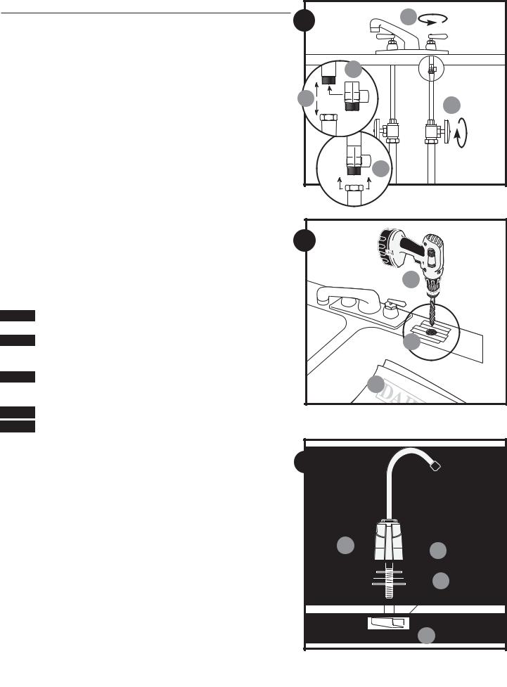
1. Installing the Water Supply Adapter |
C |
|
|
NOTE: The supply adapter fits 1/2-inch-14 NPS supply threads. If local codes permit, it may be |
A |
||
used to connect the SY-2650 to the cold water supply line. If local codes do not permit the use of |
|
|
|
the supply adapter, alternate connectors can be obtained from your local plumbing supplier. |
|
|
|
(A) Turn off the cold water supply. If cold water line does not have a shut-off valve under the sink, |
|
|
|
|
you should install one. |
|
|
(B) Turn on the cold water faucet and allow all water to drain from line. |
|
E |
|
(C) Disconnect cold water line from 1/2-inch-14 NPS threaded stub on bottom of main faucet. |
|
||
|
|
||
(D) Apply Teflon® tape onto threads of faucet stub and supply adapter. Screw the water supply |
|
|
|
|
adapter to the threaded faucet stub as shown. |
|
|
(E) Using the nut that previously connected the cold water line to the faucet, screw the cold water |
|
|
|
|
line to the male supply adapter threads. (See diagram). |
2 |
|
2. Selecting the Faucet Location |
|
||
NOTE: The drinking water faucet should be positioned with function, convenience, and appearance |
|
|
|
in mind. An adequate flat area is required to allow faucet base to rest securely. The faucet fits |
|
C |
|
through a 7/16-inch hole. Most sinks have pre-drilled 1 3/8-inch or 1 1/2-inch diameter holes that |
|
||
may be used for faucet installation. If these pre-drilled holes cannot be used or are in an inconve- |
|
|
|
nient location, it will be necessary to drill a 1/ -inch hole in the sink for the faucet. |
|
|
|
|
2 |
|
|
CAUTION: This procedure may generate dusts which can cause severe irritation if inhaled or come in contact with the eyes. The use of safety glasses and respirator for this procedure is recommended.
CAUTION: DO NOT ATTEMPT TO DRILL THROUGH AN ALL-PORCELAIN OR PORCELAIN-COATED SINK. For applications on these types of sinks we recommend using the sprayer hole or mounting the faucet through the countertop.
CAUTION: When drilling through a countertop make sure the area below the drilled area is free of
wiring and piping. Make certain that you have ample room to make the proper connections to the A bottom of the faucet.
CAUTION: Do not drill through a countertop that is more than 1-inch thick.
CAUTION: Do not attempt to drill through a tiled, marble, granite or similar countertop. Consult a plumber or the countertop manufacturer for advice or assistance.
(A) Line bottom of sink with newspaper to prevent metal shavings, parts, or tools from falling |
3 |
down drain. |
(B)Place masking tape over the area to be drilled to prevent scratches if drill bit slips.
(C)Mark hole with center punch. Use a 1/4-inch drill bit for a pilot hole, then, using a 1/2-inch drill bit, drill a hole completely through the sink. Smooth rough edges with a file.
3. Mounting the Faucet
(A) Slide small black rubber gasket OR
(B) gasket, aluminum escutcheon plate (first remove protective plastic), and large gasket onto |
A |
|
|
|
|
|
|
B |
|
threaded faucet stem. Lower faucet stem through hole in the sink. |
|
|
|
|
|
|
|
|
|
|
|
|
|
|
|
|
|
|
|
NOTE: Black rubber gasket is designed for smaller holes in sink. Aluminum escutcheon plate with |
|
|
|
|
|
|
|
|
C |
|
|
|
|
|
|
|
|
||
|
|
|
|
|
|
|
|
||
|
|
|
|
|
|
|
|
||
gaskets is designed for larger, pre-drilled holes. |
|
|
|
|
|
|
|
|
|
|
|
|
|
|
|||||
|
|
|
|
|
|||||
|
|
|
|
|
|
||||
(C) Slide aluminum channel washer up faucet stem, followed by |
|
|
|
|
|
|
|
|
|
(D) black plastic stem nut. Tighten nut with fingers. NOTE: Do not use pliers to tighten stem-nut. Pliers may strip threads of faucet stem.
 D
D
2 |
Technical Support: 1-800-645-5426, Monday |
7:30 am–5:00 pm, CST |

4. Mounting the System |
|
|
|
B |
(A) Center system between water supply adapter and drinking water faucet. |
|
|
|
4 |
NOTE: Allow 1 1/ -inches (38 mm) clearance below system for changing filter cartridges. |
|
|||
2 |
|
|
|
|
(B) Install mounting screws at least 13 3/ -inches (350 mm) from cabinet floor and 4 |
1/ |
8 |
-inches |
|
4 |
|
|
|
|
(124 mm) apart. Leave enough space (approximately 1/ -inch [13 mm]) between the head of |
4-1/8" |
|||
2 |
|
|
|
|
the screw and the wall to slip system onto screws. |
|
|
|
105 mm |
(C) Place system over screws on wall and slide downwards to lock into place. |
|
|
|
|
|
|
|
|
|
CAUTION: Make certain system is firmly attached to wall to prevent it from falling and possibly |
C |
|||
being damaged. |
|
|
|
|
|
|
|
|
13-3/ " |
|
|
|
|
4 |
|
|
|
|
350 mm |
|
|
|
|
A |
|
|
|
|
1-1/ " |
|
|
|
|
2 |
|
|
|
|
38 mm |
5. Connecting the Faucet
CAUTION: Do not over-tighten compression nut. Use caution not to bend or crimp tubes when securing.
(A) Determine the length of plastic tubing needed to connect the outlet (right) side of the filter with the faucet. Measure tubing short enough to prevent kinking and cut the tubing squarely. Screw nut of faucet stem hand tight, then unscrew two turns.
NOTE: Compression nut should come preassembled with ferrules inside. If nut should come apart, see figure 5A for proper assembly.
(B) Push the tubing firmly into the end of the faucet stem. Hand-tighten compression nut onto |
|
|
B |
|
threads until secure. Then tighten 1 1/2 to 2 turns with wrench. |
|
|
|
|
|
|
A |
|
|
6. Connecting the Supply Adapter |
6 |
A |
5 |
|
(A) Determine the length of plastic tubing needed to connect the inlet (left) side of the filter with |
|
/8" |
||
16 mm |
||||
the supply adapter. Be sure to allow enough tubing to prevent kinking and cut the tubing |
|
|||
squarely. Place a mark 5/8-inch from the end of the tubing. |
|
|
|
|
(B) Wet tubing with water and insert into supply adapter 5/ -inch until mark is flush with fitting. |
|
|
|
|
8 |
|
|
|
|
NOTE: Disconnecting the Tubing from the Quick-Connect Fittings: Routine maintenance and |
|
|
|
|
cartridge replacement will not require that you disconnect the tubing from the filter system; |
|
B |
||
however, tubing may be quickly and easily removed from the fittings if necessary. First, turn off the |
|
|||
water supply to the filter. Open faucet, then press in the gray collar around the fitting while pulling |
|
|
|
|
the tubing with your other hand. |
|
|
|
|
|
|
|
5/8" |
|
7. Connecting the System |
|
|
16 mm |
|
|
|
|
||
(A) Assemble tubing with system as shown in Fig. 7A, inserting tubing into appropriate inlet or |
|
|
5/8" |
|
outlet quick-connect fitting until it stops. |
|
|
||
NOTE: In some installations, connecting the system to the supply adapter and/or drinking water |
7 |
A |
16 mm |
|
|
||||
faucet causes the tubing to enter the quick-connect fitting at a sharp angle. This may exert |
|
|
|
|
pressure on the quick-connect fitting and cause it to leak. In these situations, you may wish to use |
|
|
|
|
one or both of the quick-connect elbows included with the installation kit. Simply push the quick- |
|
|
|
|
connect elbow directly into the quick-connect fitting on the system, then insert the tubing into the |
|
|
|
|
quick-connect elbow. |
|
|
|
|
(B) When cut between a set of black guide arrows, the tubing should be pushed into the fitting so |
|
|
|
|
that the entrance of the fitting falls between the next set of guide arrows (approximately 5/ |
|
|
|
|
8 |
|
B |
|
|
inch [16 mm]). |
|
|
||
Technical Support: 1-800-645-5426, Monday- |
|
7:30 am–5:00 pm, CST |
3 |
|
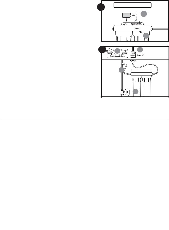
8. Installing the Battery
(A)Remove cover on top of system. Attach 9-volt battery (included) to connector, then place battery in holder located to the left of the monitor panel as shown (Fig. 8A).
(B)Replace cover on top of system. Using a pen or pencil, press and release the blue reset button on the front of the system (Fig. 8B). The electronic monitor should beep twice. If the monitor has been reset properly, the two beeps will be followed by a sequence of two green, two yellow, and two red lights. The monitor should be reset whenever a new set of filter cartridges is installed.
9. Putting the System into Operation
(A) Slowly turn on cold water supply.
8 |
A |
B |
(B)Shut off cold water faucet opened before starting installation.
(C)Rotate base of drinking water faucet counter-clockwise to “ON” position. Allow water to run for 5 minutes to flush air and carbon fines from filter cartridges. Turn off drinking water faucet. Check system for leaks before leaving installation.
NOTE:
•It is recommended that you run the tap at least 20 seconds prior to using water for drinking or cooking purposes.
•Initially, filtered water may appear cloudy. If you set a glass of water on a level surface, you should be able to watch the cloudiness disappear from the bottom of the glass upwards. This harmless cloudiness results from the release of trapped air within the cartridge and will disappear within a few weeks after installation.
INSTALLATION IS NOW COMPLETE.
Electronic Monitor Operations
A
The SY-2650 system includes an electronic monitor that alerts you when it is time to change your filter cartridges. Both filter cartridges should be changed at the same time to ensure that the monitor works properly. The monitor measures actual water usage and is powered by a single 9-volt battery.
How the Electronic Monitor Works
The filter cartridges in the SY-2650 should be replaced every 500 gallons. The electronic monitor uses a combination of lights and alarms to alert you at different stages during the life of the filter cartridges. The lights are visible on the front panel of the filter system, to the left of the blue reset button:
0-475 gallons No alarm. Green light flashes when water is turned on.
475-500 gallons Alarm BEEPS ONCE when water is turned on. Yellow light flashes when water is on.
Replacing the Battery
The battery should be replaced every time new filter cartridges are installed or after 12 months of operation, whichever comes first.
Replacing Battery and Filters at the Same Time: Install new 9-volt battery as described in Step Eight: Installing the Battery on p. 4. Make sure to press blue reset button on front panel of system when finished.
Replacing Battery Only: Remove the old battery and install the new battery. DO NOT press the reset button on the front panel of the system when finished.
500+ gallons Alarm BEEPS TWICE when water is turned on. Red light flashes when water is on.
Low or Dead battery No alarm. No lights. Replace battery.
NOTE: Gallons used while battery is dead will register on meter when battery is replaced
NOTE: To extend battery life, any sequence that includes any beeps will not be repeated if water is turned on again in less than 15 minutes.
Reset Button
The blue reset button is located on the front panel of the system. This button should only be pressed during initial installation or when new filter cartridges are installed. After pressing and releasing the button, you will hear two beeps followed by a sequence of two green, two yellow, and two red lights. This combination of beeps and lights indicates that the system has properly reset the internal gallon counter.
4 |
Technical Support: 1-800-645-5426, Monday |
7:30 am–5:00 pm, CST |

Filter Cartridge Replacement
•Filter cartridges for the SY-2650 will last about 500 gallons or six months before they need to be replaced. Filter cartridge life varies depending on usage, and/or water conditions. Changes in taste, color, and flow of the water being filtered indicate that the cartridge should be replaced.
•Read all instructions before replacing filter cartridges.
 WARNING: Use safety glasses and gloves when handling household bleach to prevent bodily injury. Follow bleach manufacturer's instructions when handling bleach.
1.Close water supply valve and open drinking water faucet to release pressure from system.
2.Using the housing wrench, unscrew and remove bottom of filter housing. Locate and remove large O-ring, wipe clean of lubricant, and set aside. Repeat for second housing.
3.Discard used filter cartridges. Using a non-abrasive sponge or cloth, scrub the bottom of filter housings, O-ring grooves, and caps with dish soap and
warm water. Rinse thoroughly. Fill bottom of each housing 1/3 full with water. Add 1 teaspoon of household bleach and scrub to disinfect.
4.Lubricate O-rings with silicone grease. Insert each O-ring in groove and press into place.
NOTE: This step is important to ensure a proper housing seal. Make certain each O-ring is seated level in its groove or a leak may occur.
5.Screw bottom of housings with bleach water onto caps without filter and hand-tighten. DO NOT OVER-TIGHTEN.
6.Turn on water supply. Let faucet run for about 10 seconds, then turn off faucet and let stand for 20-30 minutes.
7.Turn on faucet and allow bleach water to run out (about 3-5 minutes).
8.Turn off water supply to system and open faucet to release pressure. Remove bottom of housings and empty of water.
9.Insert each filter cartridge into appropriate filter housing:
SY-2650: D-250A Cartridge Set: White with green end caps in left housing.
Grey plastic cartridge in right housing
10.Screw bottom of housings onto caps and hand-tighten. DO NOT OVERTIGHTEN. Make certain cap standpipe slips into cartridge.
11.Open water supply valve and turn on drinking water faucet to release pressure in system. Let faucet run for 5 minutes to remove trapped air and carbon fines. Check system for leaks before leaving installation.
12.Press blue reset button.
NOTE:
•It is recommended that you run the tap at least 20 seconds prior to using water for drinking or cooking purposes.
•Initially, filtered water may appear cloudy. If you set a glass of water on a level surface, you should be able to watch the cloudiness disappear from the bottom of the glass upwards This harmless cloudiness results from the release of trapped air within the cartridge and will disappear within a few weeks after installation.
Troubleshooting
Leaks:
…between cap and bottom of filter housing
Turn off water supply valve and turn on drinking water faucet to release pressure in system. Remove bottom of housing. Clean O-ring and O-ring groove (located directly beneath threads of housing). Lubricate O-ring with silicone grease and replace securely into groove. Screw bottom of housing onto cap and hand-tighten. DO NOT OVER-TIGHTEN. Turn on water supply valve and check for leaks.
…on system inlet/outlet connections
Turn off water supply valve and turn on drinking water faucet to release pressure in system. Remove tubing from fitting (see NOTE under Step Six: Connecting the Supply Adapter on p.3) and make sure end of tubing is cut squarely and free of scratches or burrs. Reinsert tubing into quick-connect fittings, making sure to push securely until tubing hits a hard stop. Turn on water supply valve and check for leaks.
…on supply adapter connection
Turn off water supply valve and turn on drinking water faucet to release pressure in system. Loosen leaking threaded fitting on supply adapter or pull out leaking tubing from fitting. Inspect to see if plastic tubing is scratched or supply adapter was properly attached. If tubing is scratched, cut off 1/2-inch to 5/8-inch and reinstall per Step Six: Connecting the Supply Adapter. Reconnect tubing or tighten compression nut with fingers, then tighten nut snugly 1/2-turn with wrench. Turn on water supply valve and check for leaks.
…on faucet/tubing connection
Turn off water supply valve and turn on drinking water faucet to release pressure in system. Loosen and remove compression nut fitting on faucet stem. Make sure tubing is inserted firmly into end of faucet stem, then retighten compression nut with fingers until secure then tighten 1 turn with a wrench. Turn on water supply valve, then turn off faucet to check for leaks.
NOTE: If leaks persist, or if there are other leaks on system, turn off water supply. Call our technical support department at 1-800-645-5426.
Low Water Flow
1.Check flow at faucet. The SY-2650 system should fill a gallon jug in approximately 2 minutes. Flow rates will vary with individual household water pressure.
2.Check filter cartridge installation. Make certain both filter cartridges are properly oriented in filter housings (See Filter Cartridge Replacement on p. 5).
3. Check to be certain that the water supply valve is completely open (turn handle on valve counter-clockwise as far as it will go).
4.Check flow through empty system. To do this, turn off water supply valve and turn on drinking water faucet to release pressure in system. Then remove filter cartridges from housings and screw housings back onto caps. Turn on faucet to check flow through empty system. Flow should be about one to two gallons per minute. If flow is less than 0.4 gallons per minute, call Technical Support at 1-800-645-5426.
5.If flow through empty system is adequate, place one filter cartridge in system at a time and check flow to make sure cartridge is not clogged. Replace clogged cartridge if necessary.
Technical Support: 1-800-645-5426, Monday-Friday, 7:30 am–5:00 pm, CST |
5 |
 Loading...