


Cat. No. 01021604
Rev. A 02/01/09
DCO # 010884
Owners Guide
& Installation
Instruction
Supplement
Soft-Minder® Twin
Water Softener
Models from 2009
© 2009 Culligan International Company
Thank You
And welcome to your new world of better living with Culligan water.
The Culligan Soft-Minder® Twin Water Softeners are tested and certified by WQA according to WQA
S-100 for calcium and magnesium reduction (hardness).
For installations in Massachusetts, the Commonwealth of Massachusetts Plumbing Code 248 CMR shall be adhered to. Consult your licensed plumber for installation of the system. This system and its installation must comply with state and local regulations. The use of saddle valves is not permitted.
If this is your first experience having soft, conditioned water in your home, you’ll be amazed at the marvelous difference it makes. We promise that you’ll never want to be without it again.
With Culligan’s many years of knowledge and experience in water treatment, you can be confident that the model you selected has been designed and engineered to provide years of service with a minimum of care and attention.
Some localities have corrosive water. A water softener cannot correct this problem and so its printed warranty disclaims liability for corrosion of plumbing lines, fixtures or appliances. If you suspect corrosion, your Culligan Dealer has equipment to control the problem.
Sodium Information: Water softeners using sodium chloride for regeneration add sodium to the water. Persons who are on sodium restricted diets should consider the added sodium as part of their overall sodium intake.
This supplement contains important information about the Soft-Minder Twin automatic water conditioner, including instructions covering installation of the control valve, tank adapter, interconnection piping between the two mineral tanks, and timer adjustments. For additional information, please refer to the Model 9100 Service manual packed with the control.
Before starting the installation, make certain the water meets the required limitations as shown in the specifications. Review the specifications for the unit to be certain all applications requirements have been met. Also, carefully review the Model 9100 Service
Manual, paying particular attention to the regeneration cycle program setting procedure and start-up procedure.
Performance Data Sheets are included in this manual for various Culligan Soft-Minder Twin Softener models. Refer to the
Performance Data Sheet for your specific softener, as there are slight differences between the models. The softener warranty is located on page 18 of this Owner’s Guide.
Attention Culligan Customer:
Your local independently operated Culligan dealer employs trained service and maintenance personnel who are experienced in the installation, function and repair of Culligan equipment.
This publication is written specifically for these individals and is intended for their use.
We encourage Culligan users to learn about Culligan products, but we believe that product knowledge is best obtained by consulting with your Culligan dealer. Untrained individuals who use this manal assume the risk of any resulting property damage or personal injury.
 Warning! Prior to servicing equipment, disconnect power supply to prevent electrical shock.

Owners Guide
& Installation
Instruction
Supplement
Soft-Minder® Twin
Water Softener
Models from 2009
Table of Contents |
Page |
Specifications . . . . . . . . . . . . . . . . . . . . 4
Introduction. . . . . . . . . . . . . . . . . . . . . 5
Preparation. . . . . . . . . . . . . . . . . . . . . 8
Installation. . . . . . . . . . . . . . . . . . . . . 10
Control Start-up Procedures. . . . . . . . . . . . . . 12
Diagnostics. . . . . . . . . . . . . . . . . . . . 22
Salt Supply, Usage & Service. . . . . . . . . . . . . 26
Care & Cleaning . . . . . . . . . . . . . . . . . . 27
Service Check List. . . . . . . . . . . . . . . . . . 29
Error Codes. . . . . . . . . . . . . . . . . . . . 30
Culligan 61 Soft-Minder Twin Performance Data Sheet. . . 31
Culligan 91 Soft-Minder Twin Performance Data Sheet. . . 32
Parts List. . . . . . . . . . . . . . . . . . . . . 33
Records and Data. . . . . . . . . . . . . . . . . . 41
Wiring Diagram. . . . . . . . . . . . . . . . . . . 42
Warranty. . . . . . . . . . . . . . . . . . . . . 43
Promise. . . . . . . . . . . . . . . . . . . . . . 44
Table of Contents

Specifications
Twin Specifications
|
SM-61 Model |
SM-91 Model |
|
|
|
Control Valve |
Reinforced Thermoplastic |
Reinforced Thermoplastic |
|
|
|
Overall Conditioner Height |
|
|
Media Tank Design |
Quadra-Hull |
Quadra-Hull |
Media Tank Dimensions (Dia x Ht) |
9 x 48 in |
10 x 54 in |
|
|
|
Salt Storage Tank Dimensions (Dia x Ht) |
16 x 43 in |
18 x 43 in |
|
|
|
|
18 x 43 in |
|
Exchange Media, Type and Quantity |
Cullex® Media, 1.0 ft3 |
Cullex® Media, 1.5 ft3 |
Underbedding, Type and Quantity |
Cullsan® |
Cullsan® |
|
Underbedding, 12 lb |
Underbedding, 15 lb |
Exchange Capacity |
13,760 gr @ 3.3 lb |
21,193 gr @ 5 lb |
|
|
|
@ Salt Dosage Per Recharge |
27,848 gr @ 9.3 lb |
42,890 gr @ 14 lb |
|
|
|
|
32,939 gr @ 15 lb |
50,732 gr @ 22.5 lb |
Efficiency rated dosage1 |
4130 gr/lb @ 3.3 lb salt dosage |
4,240 gr/lb @ 5 lb salt dosage |
Freeboard to Media2 |
14.5 in |
14.5 in |
Freeboard to Underbedding3 |
44.5 in |
47.5 in |
Salt Storage Capacity |
250 lb or 375 lb |
375 lb |
Rated Service Flow @ Pressure Drop |
10.4 gpm @ 15 psi |
10.2 gpm @ 15 psi |
|
|
|
Total Hardness, Maximum |
75 gpg |
99 gpg |
|
|
|
Total Iron, Maximum |
5 ppm |
5 ppm |
Hardness to Iron Ratio, Minimum |
8 gpg to 1 ppm |
8 gpg to 1 ppm |
Operating Pressure |
20-125 psi |
20-125 psi |
|
|
|
Operating Temperature |
33-120°F |
33-120°F |
|
|
|
Electrical Requirements |
24V/60 Hz |
24V/60 Hz |
Electrical Power Consumption, Min/Max |
5 Watts/ 6 Watts |
5 Watts/ 6 Watts |
Drain Flow, Maximum4 |
2 gpm |
2 gpm |
Recharge Time, Average5 |
67 min |
67 min |
Recharge Water Consumption, Average5 |
57 gal |
57 gal |
1 The efficiency rated dosage is only valid at the stated salt dosage and is efficiency rated according to NSF/ANSI 44.
2Measured from top of media to top surface of tank threads. (backwashed and drained).
3Measured from top of underbedding to top surface of tank threads.
4Backwash at 120 psi (830 kPa).
510 minute backwash, 3.3 lb 9” model, 5 lb (2.7kg) 10” model.
Culligan Platinum Plus® Series

Introduction
It’s All So Easy, So Economical, So Efficient, So Enjoyable!
Kind To Skin And Complexion
Soft water will help prevent red, itchy or dry skin because there are no hardness impurities to cause soreness, no soap curd to coat the skin. Shaving is easier, smoother - either with blade or electric shaver.
Bathing And Showering
You’ll use far less soap with conditioned water. Use your soap very sparingly - not as you did before soft water. Just a quick rinse removes all lather, leaving your skin pleasantly smooth and silky - because now it’s free of sticky soap curd and film.
Saves Washing Costs. Helps Control Environmental Pollution
Soft water washes whiter and cleaner with less soap or detergent. Because the hardness impurities are removed, your soap can concentrate solely on washing. People usually find that they can reduce the amount of soap they use substantially. If you normally used a cup per wash load with hard water, try using only 1/3 cup depending on the size of your wash load and the degree of soil.
Different amounts are required, but you can use less with softened water. An added bonus is the fact that your washable fabrics will last longer.
Super Hair Conditioning
Soft water is great for scalp and hair care. No insoluble deposits are formed. Hair is shinier, softer, more manageable. Reduce the amount of shampoo you have normally used.
Dishes Are A Delight
Washed by hand or in a dishwasher, glassware, dishes and silver wash cleaner, easier. Follow your dishwasher manufacturer’s instructions. Soft water promotes sanitation because no greasy hard water film can form to collect or harbor bacteria.
Easier Housekeeping, Gleaming Fixtures
You’ll be amazed at the marvelous difference. Just a swish of the cloth, and the bathtub or shower and fixtures are clean and sparkling. Imagine, no scouring! No hard water scum to cause rings, streaks, spots and stains. To keep their gleaming luster, simply wipe fixtures with a towel after use. Formica, tile, walls, floors, woodwork surfaces clean easier, stay clean longer. You’ll save on cleaning aids and save on time.
Saves Water-heating Energy, Helps Water-using Appliances
Soft water reduces the formation of rock-like hard water scale which encrusts water heaters, hot water pipes, shower heads, and water-using appliances. This scale can cause premature maintenance and failure.
Elimination of hard water also provides substantial energy savings because scale acts as an insulator, wasting electricity or gas used to heat water.
Savings Galore
A water conditioner is frequently referred to as “the appliance that pays for itself”. You’ll find that your savings on soaps, detergents, cleaning aids, and personal care products will help your family’s household budget. And if you place a price on your time, you’ll be most happy with the time saved by your new family servant.
Water For Lawns And Household Plants
If possible, lawn sprinkling faucets should be supplied with hard water primarily because it is uneconomical to soften so much water.
Household plants are much more sensitive than lawns with respect to the kind of water which is best. First, because they receive no rainfall and, second, there is little or no drainage of the soil. Preferably they should be watered with rain water or water which is low in mineral content such as distilled or demineralized water. Softened water is not recommended for house plants because a build-up of sodium in the soil may interfere with efficient absorption of water by the plant root system. Additional information may be obtained from your independently operated Culligan dealer.
Introduction

How Your Water Conditioner Works
Why Water Gets Hard And How It’s Softened
All of the fresh water in the world originally falls as rain, snow, or sleet. Surface water is drawn upward by the sun, forming clouds. Then, nearly pure and soft as it starts to fall, it begins to collect impurities as it passes through smog and dust-laden atmosphere. And as it seeps through soil and rocks it gathers hardness, rust, acid, unpleasant tastes and odors.
Water hardness is caused primarily by limestone dissolved from the earth by rainwater. Because of this, in earlier times people who wanted soft water collected rainwater from roofs in rain barrels and cisterns before it picked up hardness from the earth.
Some localities have corrosive water. A softener cannot correct this problem and so its printed warranty disclaims liability for corrosion of plumbing lines, fixtures or appliances. If you suspect corrosion, your Culligan Man has equipment to control the problem.
Iron is a common water problem. The chemical/physical nature of iron found in natural water supplies is exhibited in four general types.
1.Dissolved Iron - Also called ferrous or “clear water” iron. This type of iron can be removed from the water by the same ion exchange principle that removes the hardness elements, calcium and magnesium. Dissolved iron is soluble in water and is detected by taking a sample of the water to be treated in a clear glass. The water in the glass is initially clear, but on standing exposed to the air, it may gradually turn cloudy or colored as it oxidizes.
2.Particulate Iron - Also called ferric or colloidal iron. This type of iron is an undissolved particle of iron. A softener will remove larger particles, but they may not be washed out in regeneration effectively and will eventually foul the ion exchange resin. A filtering treatment will be required to remove this type of iron.
3.Organic Bound Iron - This type of iron is strongly attached to an organic compound in the water. The ion exchange process alone cannot break this attachment and the softener will not remove this type of iron.
4.Bacterial Iron - This type of iron is protected inside a bacteria cell. Like the organic bound iron, it is not removed by a water softener.
When using a softener to remove both hardness and dissolved iron it is important that it regenerates more frequently than ordinarily would be calculated for hardness removal alone. Although many factors and formulas have been used to determine this frequency, it is recommended that the softener be regenerated when it has reached 50 - 75% of the calculated hardness alone capacity. This will minimize the potential for bed fouling (Iron removal claims have not been verified by the Water Quality Association).
If you are operating a water softener on clear water iron, regular resin bed cleaning is needed to keep the be from coating with iron. Even when operating a softener on water with less than the maximum of dissolved iron, regular cleanings should be performed. Clean every six months or more often if iron appears in your conditioned water supply. Use resin bed cleaning compounds carefully following the directions on the container.
Caution! Do not use where the water is microbiologically unsafe or with water of unknown quality without adequate disinfection before or after the unit.
Hardness sample kits are available through your local Culligan dealer.
Culligan Soft-Minder Twin® Softeners

The Culligan Process
Your Culligan water conditioner consists of three basic components, (A) the Control Valve, (B) the Mineral Tank, and (C) the Brine System.
A.The exclusive Culligan control valve automatically performs a variety of tasks that are necessary for the proper operation of your water conditioner. These tasks, commonly referred to as cycles or operating positions, are: Service, Regeneration, and
Brine Refill.
1.Service: While the control valve is in the “Service cycle”, hard water is directed down through the column of Cullex® resin where hardness minerals are removed from the water. The softened water is then directed into your household plumbing lines. The ability of the Cullex resin to remove hardness minerals needs to be periodically replenished; this is referred to as . . .
2.Regeneration: While the control valve is in the “Regeneration cycle”, water is first directed up through the column of Cullex resin to flush accumulated sediment out of the resin and down the drain. Then, the regenerant brine solution is slowly drawn from the bottom of the salt storage tank of the Brine System and is directed down through the column of Cullex resin, restoring the ability of the resin to remove hardness minerals from your water supply. Once completed, the regeneration cycle is followed by . . .
3.Brine Refill: While the control valve is in the “Brine Refill cycle”, a predetermined amount of water is directed to the salt storage tank of the Brine System so that additional salt can be dissolved to provide the brine solution that will be needed for the next regeneration cycle.
B.The exclusive Quadra-Hull® Mineral Tank contains the Cullex resin column, Cullsan® underbedding, and an outlet manifold. The number of gallons of hard water that can be softened by the Cullex resin column before it needs regeneration is called the “capacity” of the resin column, and depends upon the amount of hardness minerals in each gallon of water (expressed as grains per gallon) and upon the amount of regenerant brine solution (expressed as pounds of salt) passed through the resin column during regeneration.
Your Culligan service person, taking into account the hardness of your water and the amount of softened water your household may reasonably expect to use each day, has carefully established how often the softener will regenerate and how much salt will be used for each regeneration. This will ensure that all of your soft water needs will be fulfilled without using an excessive amount of salt.
C.The Brine System consists of a salt storage container and hydraulic Dubl-Safe valve. The salt storage container holds the salt that is used to make the regenerant brine solution. The hydraulic Dubl-Safe valve limits the amount of water that is returned to the salt storage tank during the brine refill cycle.
Since a predetermined amount of salt is dissolved with each brine refill cycle, the salt must be periodically replenished in order to maintain efficient operation. Your Culligan service person will be able to tell you about how often salt must be added to the salt storage container.
Introduction
Preparation
Component Description
The water conditioner is shipped from the factory in a minimum of four cartons. Remove all components from their cartons and inspect them before starting installation.
Control Valve Assembly - Includes the Soft-Minder Twin Control. Small parts packages will contain additional installation hardware, and the conditioner Owner’s Guide.
Media Tank - Includes Quadra-Hull® media tank complete with Cullex® ion exchange resin, underbedding and outlet manifold.
Salt Storage Tank Assembly - Includes salt storage container with support plate and Dubl-Safe™ brine refill valve and chamber.
Bypass Valve - Includes the stainless steel bypass valve and pins.
Tools and Materials
The following tools and supplies will be needed, depending on installation method. Observe all applicable codes.
Note: Check and comply with your state and local codes. You must follow these guidelines.
For installations in Massachusetts, the Commonwealth of Massachusetts Plumbing Code 248 CMR shall be adhered to. Consult your licensed plumber for installation of the system. This system and its installation must comply with state and local regulations. The use of saddle valves is not permitted.
All Installations
•Safety glasses
•Phillips screwdrivers, small and medium tip.
•Gauge assembly (PN 00-3044-50 or equivalent)
•Silicone lubricant (PN 00-4715-07 or equivalent) - DO NOT USE PETROLEUM-BASED LUBRICANTS
•A bucket, preferably light-colored
•Towels
Special Tools
•Torch, solder and flux for sweat copper connections
•Use only lead-free solder and flux for all sweat-solder connections, as required by state and local codes.
•Threading tools, pipe wrenches and thread sealer for threaded connections.
•Saw, solvent and cement for plastic pipe connections.
Materials
•Brine line, 5/16” (PN 00-3031-28 or equivalent)
•Drain line, 1/2” (PN 00-3030-82, gray, semi-flexible; or PN 00-3319-46, black, semi-rigid; or equivalent)
•Thread sealing tape
•Pressure reducing valve (if pressure exceeds 125 psi [860 kPa], PN 00-4909-00 or equivalent)
•Pipe and fittings suited to the type of installation
•Water softener salt (rock, solar or pellet salt formulated specifically for water softeners)
Culligan Soft-Minder Twin® Softeners
Application
Water quality - Verify that raw water hardness and iron are within limits. Note the hardness for setting the salt dosage and recharge frequency.
Pressure - If pressure exceeds 125 psi (860 kPa), install a pressure reducing valve (see materials checklist). On private water systems, make sure the minimum pressure (the pressure at which the pump starts) is greater than 20 psi (140 kPa). Adjust the pressure switch if necessary.
 Caution! The use of a pressure reducing valve may limit the flow of water in the household.
Temperature - Do not install the unit where it might freeze, or next to a water heater or furnace or in direct sunlight. Outdoor installation is not recommended and voids the warranty. If installing in an outside location, you must take the steps necessary to assure the softener, installation plumbing, wiring, etc. are as well protected from the elements (sunlight, rain, wind, heat, cold), contamination, vandalism, etc. as when installed indoors.
Location
Space requirements - Allow 6-12 inches (15-30 cm) behind the unit for plumbing and drain lines and 4 feet (1.3 meters) above for service access and filling the salt container (See figure 1).
Floor surface - Choose an area with solid, level floor free of bumps or irregularities. Bumps, cracks, stones and other irregularities can cause the salt storage tank bottom to crack when filled with salt and water.
Drain facilities - Choose a nearby drain that can handle the rated drain flow (floor drain, sink or stand pipe). Refer to the Drain
Line Chart, Table 1 (page 11), for maximum drain line length.
Note: Most codes require an anti-siphon device or air gap. Observe all local plumbing codes and drain restrictions. The system and installation must comply with all state and local laws and regulations. Waste connections or drain outlets shall be designed and constructed to provide for connection to the sanitary waste system through an air gap of 2 pipe diameters or 25 mm (1 in.), whichever is larger.
Electrical facilities - A 10-foot cord and wall mount plug-in transformer are provided. The customer should provide a receptacle, preferably one not controlled by a switch that can be turned off accidentally. Observe local electrical codes.
Note: The softener works on 24 volt - 60 Hz power only. Be sure to use the included transformer. Be sure the electrical outlet and transformer are in an inside location to protect from moisture. Properly ground to conform with all governing codes and ordinances.
Preparation

Installation
Use this installation supplement with the Fleck Service Manual and Timer Supplemental Service Manual. This addendum supplements the Fleck 9100 Service Manual and Timer Service Manual.
|
TO HOSE BIBS |
|
TREATED WATER OUT |
DRAIN |
|
LINE |
HARD WATER IN |
AIR |
|
GAP |
|
|
HEATER |
|
BRINE |
|
TANK |
|
WATER |
|
METER |
|
OR |
|
PUMP |
|
SOFT-MINDER TWIN |
|
Figure 1 |
Placement
•Set the media tanks on a solid, level surface that provides easy access to a water supply, drain system and electricity.
•Place the brine system on a flat, smooth, solid surface close to the media tank.
•Plumbing should comply with the applicable state and local plumbing codes.
•Connect the couplings and yoke assembly to the control valve and tank adapter. Lubricate the O-ring with silicone lubricant.
•Lubricate the distributor and tank O-ring seal with silicone lubricant.
•The joints near the drain must be soldered prior to connecting the drain line flow control fitting (DLFC). Leave at least 6” between the DLFC and the joints when soldering. Failure to do this could cause damage to the drain module. Teflon tape is the only sealant to be used on the drain fittings.
Control Valve
A 0.5 gpm BLFC is installed in the control valve. A 0.25 gpm BLFC is included in the control parts pack that needs to be used on
9” tank when salt dosage is less than 5 lbs. Remove the BLFC from the brine valve. Install the BLFC by removing the brine fitting, remove the retainer, remove and replace with the proper size.
A white #1 eductor throat and nozzle is packaged with the control valve for use on the 9-inch tanks. See table 2 (page 19) for eductor throat and nozzle selections.
When changing the eductor nozzle and throat, remove the eductor assembly mounting screws. Carefully remove the eductor assembly from the control. Unscrew the eductor nozzle and throat and replace with the correct size eductor. Reassemble onto the control valve.
Included in the parts pack are drain line flow controls with different gpm capacities. Tank size will determine which size flow control to install. Use the 2.00 gpm for the 9-inch tank and 10-inch tank. See table 2 (page 19) for DLFC selections
Install the DLFC by removing the drain line elbow adapter. Unscrew |
Figure 2 |
10 Culligan Soft-Minder Twin® Softeners
the retainer, remove and replace with the proper size.
Install the retainer and the drain line elbow adapter. The numbered side of the DLFC must face down.
Start-Up
Place approximately 1” of water above the grid plate (if used) in your salt tank. Salt may be placed in the unit at this time.
Place softener in a bypass position. Turn on the main water supply and check for any leaks. Open a cold water faucet near the softener and run a few minutes until the system is free of any foreign material (usually solder) that may have resulted from the installation.
Plug unit into electrical outlet. Do not insert meter cable into the meter at this time. Electrical connections must be connected according to codes.
Advance the softener control to the backwash position. Slowly shift the bypass into the service position so that the water flows into the mineral tanks. When water appears at the drain, shift the bypass valve to fully open. Continue to backwash until the water at drain is clear.
Start REGEN to fill second tank. Backwash until the water at drain is clear.
Height of Discharge Above Floor Level Operating - Table 1
Operating |
0 ft (0 m) |
2ft (0.6 m) |
4 ft (1.2 m) |
6 ft (1.8 m) |
8 ft (2.4 m) |
10 ft (3 m) |
|
Pressure |
|||||||
|
|
|
|
|
|
||
|
|
|
|
|
|
|
|
30 psi (210 kPa) |
60 ft (18 m) |
50 ft (15 m) |
30 ft (9 m) |
15 ft (5 m) |
Not Allowable |
Not Allowable |
|
40 psi (279 kPa) |
100 ft (30 m) |
90 ft (27 m) |
70 ft (21 m) |
50 ft (15 m) |
30 ft (9 m) |
12 ft (4 m) |
|
|
|
|
|
|
|
|
|
50 psi (349 kPa) |
145 ft (41 m) |
115 ft (35 m) |
80 ft (24 m) |
80 ft (24 m) |
60 ft (18 m) |
40 ft (12 m) |
|
|
|
|
|
|
|
|
|
60 psi (419 kPa) |
|
|
100 ft (30 m) |
100 ft (30 m) |
85 ft (26 m) |
60 ft (18 m) |
|
80 psi (559 kPa) |
Normal Installation should not require more than |
140 ft (43 m) |
120 ft (37 m) |
||||
100 psi (699 kPa) |
|
100 ft (30 m) of drain line |
|
|
150 ft (46 m) |
||
|
|
|
|
|
|
|
|
Installation 11
Control Start-up Procedures
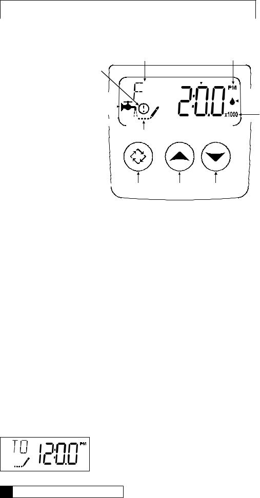
|
|
|
Parameter |
Data |
PM |
Display |
Display |
Indicator |
Error/ Information Icon
Service |
|
|
|
|
|
Flow Indicator |
|
|
|
|
|
||
|
|
|
|
|
|
|
Icon |
|
|
|
|
|
x1000 Indicator |
|
|
|
||||
|
||||||
|
|
|
|
|
|
|
|
|
|
|
|
|
|
|
|
|
|
|
|
|
Programming Icon
 Extra Cycle Button Up Button Down Button
Features of the Timer:
•Power backup that continues to keep time and the passage of days for a minimum of 48 hours in the event of power failure. During a power outage, the control goes into a power-saving mode. It does not monitor water usage during a power failure, but it does store the volume remaining at the time of power failure.
•Day-of-the-Week controls.
•While in service, the display alternates between time of day, volume remaining or days to regeneration, and tank in service (twin tank systems only).
•The Flow Indicator flashes when outlet flow is detected.
•The Service Icon flashes if a regeneration cycle has been queued.
•A Regeneration can be triggered immediately by pressing the Extra Cycle button for five seconds.
•The Parameter Display displays the current Cycle Step (BW, BF, RR, etc) during regeneration, and the data display counts down the time remaining for that cycle step. While the valve is transferring to a new cycle step, the display will flash. The parameter display will identify the destination cycle step (BW, BF, RR, etc) and the data display will read “----”. Once the valve reaches the cycle step, the display will stop flashing and the data display will change to the time remaining. During regeneration, the user can force the control to advance to the next cycle step immediately by pressing the extra cycle button.
Setting the Time of Day
1.Press and hold either the Up or Down buttons until the programming icon replaces the service icon and the parameter display reads TD.
2.Adjust the displayed time with the Up and Down buttons.
3.When the desired time is set, press the Extra Cycle button to resume normal operation. The unit will also return to normal operation after 5 seconds if no buttons are pressed.
12 Culligan Soft-Minder Twin® Softeners

Queueing a Regeneration
1.Press the Extra Cycle button. The service icon will flash to indicate that a regeneration is queued.
2.To cancel a queued regeneration, press the Extra Cycle button.
Regenerating Immediately
Press and hold the Extra Cycle button for five seconds.
Meter Immediate Control
A meter immediate control measures water usage and regenerates the system as soon as the calculated system capacity is depleted. The control calculates the system capacity by dividing the unit capacity (typically expressed in grains/unit volume) by the feedwater hardness and subtracting the reserve. Meter Immediate systems generally do not use a reserve volume. However, in twin tank systems with soft-water regeneration, the reserve capacity should be set to the volume of water used during regeneration to prevent hard water break-through. A Meter Immediate control will also start a regeneration cycle at the programmed regeneration time if a number of days equal to the regeneration day override pass before water usage depletes the calculated system capacity.
Time Clock Delayed Control
A Time Clock Delayed Control regenerates the system on a timed interval. The control will initiate a regeneration cycle at the programmed regeneration time when the number of days since the last regeneration equals the regeneration day override value.
Day of the Week Control
This control regenerates the system on a weekly schedule. The schedule is defined in Master Programming by setting each day to either “off” or “on.” The control will initiates a regeneration cycle on days that have been set to “on” at the specified regeneration time.
Control Operation During Regeneration
During regeneration, the control displays a special regeneration display. In this display, the control shows the current regeneration step number the valve is advancing to, or has reached, and the time remaining in that step.
The step number that displays flashes until the valve completes driving to this regeneration step position. Once all regeneration steps are complete the valve returns to service and resumes normal operation.
Pressing the Extra Cycle button during a regeneration cycle immediately advances the valve to the next cycle step position and resumes normal step timing.
Control Operation During Programming
The control only enters the Program Mode with the valve in service. While in the Program Mode, the control continues to operate normally monitoring water usage and keeping all displays up to date. Control programming is stored in memory permanently, eliminating the need for battery backup power.
Manually Initiating a Regeneration
1.When timer is in service, press the Extra Cycle button for 5 seconds on the main screen.
2.The timer advances to Regeneration Cycle Step #1 (backwash), and begins programmed time count down.
3.Press the Extra Cycle button once to advance valve to Regeneration Cycle Step #2 (brine draw & slow rinse).
4.Press the Extra Cycle button once to advance valve to Regeneration Cycle Step #3 (rapid rinse).
5.Press the Extra Cycle button once to advance valve to Regeneration Cycle Step #4 (brine refill).
6.Press the Extra Cycle button once more to advance the valve back to in service.
NOTE: If the unit is a filter or upflow, the cycle step order may change.
NOTE: A queued regeneration can be initiated by pressing the Extra Cycle button. To clear a queued regeneration, press the Extra Cycle button again to cancel. If regeneration occurs for any reason prior to the delayed regeneration time, the manual regeneration request shall be cleared.
Control Start-up Procedures 13

Control Operation During A Power Failure
The timer includes integral power backup. In the event of power failure, the control shifts into a power-saving mode. The control stops monitoring water usage, and the display and motor shut down, but it continues to keep track of the time and day for a minimum of 48 hours.
The system configuration settings are stored in a non-volatile memory and are stored indefinitely with or without line power. The Time of Day flashes when there has been a power failure. Press any button to stop the Time of Day from flashing.
If power fails while the unit is in regeneration, the control will save the current valve position before it shuts down. When power is restored, the control will resume the regeneration cycle from the point where power failed. Note that if power fails during a
regeneration cycle, the valve will remain in it’s current position until power is restored. The valve system should include all required safety components to prevent overflows resulting from a power failure during regeneration.
The control will not start a new regeneration cycle without line power. If the valve misses a scheduled regeneration due to a power failure, it will queue a regeneration. Once power is restored, the control will initiate a regeneration cycle the next time that the Time of Day equals the programmed regeneration time. Typically, this means that the valve will regenerate one day after it was originally scheduled. If the treated water output is important and power interruptions are expected, the system should be setup with a sufficient reserve capacity to compensate for regeneration delays.
When the Master Programming Mode is entered, all available option setting displays may be viewed and set as needed. Depending on current option settings, some parameters cannot be viewed or set.
Setting the Time of Day
1.Press and hold either the Up or Down buttons until the programming icon replaces the service icon and the parameter display reads TD.
2.Adjust the displayed time with the Up and Down buttons.
When the desired time is set, press the Extra Cycle button to resume normal operation. The unit will also return to normal operation after 5 seconds if no buttons are pressed.
Entering Master Programming Mode
Set the Time Of Day display to 12:01 P.M. Press the Extra Cycle button (to exit Setting Time of Day mode). Then press and hold the Up and Down buttons together until the programming icon replaces the service icon and the Display Format screen appears.
Exiting Master Programming Mode
Press the Extra Cycle button to accept the displayed settings and cycle to the next parameter. Press the Extra Cycle button at the last parameter to save all settings and return to normal operation. The control will automatically disregard any programming changes and return to normal operation if it is left in Master
Programming mode for 5 minutes without any keypad input.
Resets:
Soft Reset: Press and hold the Extra Cycle and Down buttons for 25 seconds while in normal Service mode.
This resets all parameters to the system default values, except the volume remaining in meter immediate or meter delayed systems and days since regeneration in the time clock system.
Master Reset: Hold the Extra Cycle button while powering up the unit. This resets all of the parameters in the unit. Check and verify the choices selected in Master Programming Mode.
14 Culligan Soft-Minder Twin® Softeners
 Loading...