


Culligan®
Sulfur-Cleer™
Automatic
Water Filter
Owners Guide
Thank You
And Welcome To Your New World Of Better Living With
Culligan Water.
This system and its installation must comply with state and local regulations. The System is ONLY to be supplied with cold water.
The Culligan® Sulfur-Cleer™ water filters have been tested against WQA S-200 for the effective reduction of iron up to 1,000 gallons and WQA Test Protocol 04-001 and NSF/ANSI Standard 42 for the effective reduction of hydrogen sulfide as verified and substantated by test data.
Do not use with water that is microbiologically unsafe or of unknown quality without adequate disinfection before or after the system.
For installations in Massachusetts, the Commonwealth of Massachusetts Plumbing Code 248 CMR shall be adhered to. Consult your licensed plumber for installation of the system. This system and its installation must comply with state and local regulations. The use of saddle valves is not permitted.
If this is your first experience having filtered, conditioned water in your home, you’ll be amazed at the marvelous difference it makes. We promise that you’ll never want to be without it again.
Congratulations, too, on selecting one of the “first family” of water filters in the prestigious Culligan Sulfur-Cleer™. With Culligan’s many years of knowledge and experience in water treatment, you can be confident that the model you selected has been designed and engineered to provide years of service with a minimum of care and attention.
Products manufactured and marketed by Culligan International Company (Culligan) and its affiliates are protected by patents issued or pending in the United States and other countries. Culligan reserves the right to change the specifications referred to in this literature at any time, without prior notice. Culligan, Culligan Sulfur-Cleer, Cullar, Filtr-Cleer, Cullneu, Accusoft, Culligan Man and www.culligan. com are trademarks of Culligan International Company or its affiliates.
ii

Specifications . . . . . . . . . . . . . . . . . . . . . . . . 1 Introduction . . . . . . . . . . . . . . . . . . . . . . . . . 2 Operating Conditions . . . . . . . . . . . . . . . . . . . . . 4 Familiarization . . . . . . . . . . . . . . . . . . . . . . . . 5 Programming . . . . . . . . . . . . . . . . . . . . . . . . 7 Statistic Functions . . . . . . . . . . . . . . . . . . . . . . 12 When and How to Bypass your Water Filter . . . . . . . . . . . . . 13 Regeneration with Bleach . . . . . . . . . . . . . . . . . . . . 14 Things to Check Before You Call for Service . . . . . . . . . . . . . 15 Preventative Maintenance . . . . . . . . . . . . . . . . . . . . 16 Troubleshooting Guide . . . . . . . . . . . . . . . . . . . . . 17 Performance Data Sheet . . . . . . . . . . . . . . . . . . . . 20 Records and Data . . . . . . . . . . . . . . . . . . . . . . 21 Warranty . . . . . . . . . . . . . . . . . . . . . . . . . 22
Table of
Contents
iii

This page intentionally left blank.
iv

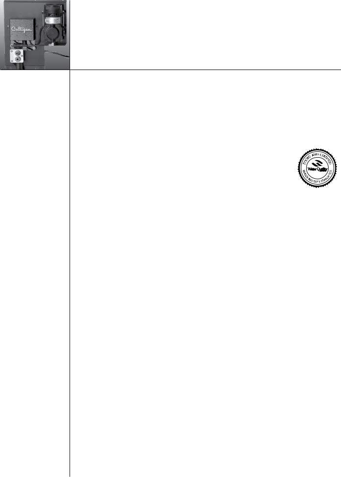
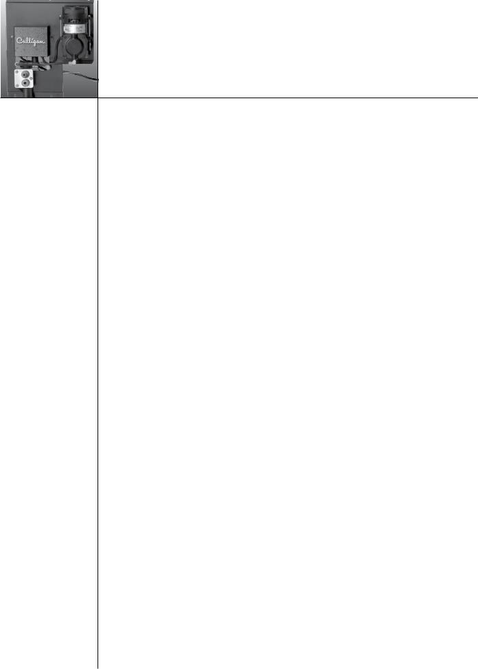
Culligan® 10” Sulfur-Cleer™ Filter with Fiberglass Tank |
|
Specifications |
|||||
Control Valve . . . . . . . . . . . . . . . . . . |
. 1” 5-cycle reinforced thermoplastic |
||||||
Timer . . . . . . . . . . . . . . . . . . . . . |
. . . |
. |
. Electronic Circuit Board |
||||
Overall Conditioner Height . . . . . . . . . . . . . |
. . . |
. |
. |
. . |
. . . . . 61” |
||
Media Tank Dimensions (D x H) . . . . . . . . . . . . |
. . |
. . |
. |
. |
. |
. |
. 10” x 54” |
Filter Media Type . . . . . . . . . . . . . . . . . |
. . |
. . |
. |
. |
. |
1.5 cu. ft. CIM |
|
Underbedding . . . . . . . . . . . . . . . . . . . . . . . . . Cullsan®, 20 lbs. |
|||||||
Capacity1 . . . . . . . . . . . . . . . . . . . . . . . . . . . . 1000 gallons |
|||||||
Freeboard2 . . . . . . . . . . . . . . . . . . . |
. . . |
. |
. |
. . |
. . . . . 18” |
||
Max. Clear Water (Soluble) Iron . . . . . . . . . . . |
. . . . . . . . . . 10 ppm |
||||||
Max. Hydrogen Sulfide5 . . . . . . . . . . . . . . . . . . . . . . . . . 8 ppm |
|||||||
Minimum Alkalinity . . . . . . . . . . . . . . . . |
. . . |
. |
. |
. . |
. |
. |
. 100 ppm |
pH . . . . . . . . . . . . . . . . . . . . . . |
. . |
. . |
. |
. |
. |
. . 7.0 - 8.5 |
|
Service Flow @ Pressure Drop (Clean Bed) Normal . . . . . |
. . . |
. |
. |
. . |
. 5 gpm @ 4 psi |
||
Maximum3 . . . . . . . . . . . . . . . . . . . |
. . . |
. |
. |
. . |
. 3 gpm @ 5 psi |
||
Operating Pressure . . . . . . . . . . . . . . . . . . . . . . . . . . 20-60 psi |
|||||||
Operating Temperature . . . . . . . . . . . . . . . |
. . |
. . |
. |
33-120° F (1-48° C) |
|||
Electrical Requirements . . . . . . . . . . . . . . . |
. . |
. . |
. |
. |
120 Volts/60 Hz |
||
Power Consumption, Continuous/Maximum . . . . . . . . |
. . |
. . |
. |
. |
7 watts/270 watts |
||
Drain Flow, Maximum . . . . . . . . . . . . . . . |
. . . |
. |
. |
. . |
. |
. |
. 5.5 gpm |
Backwash Regeneration Time . . . . . . . . . . . . . |
. . |
. . |
. |
. |
. |
.1 - 99 minutes |
|
Eduction . . . . . . . . . . . . . . . . . . . . |
. . . |
. |
. |
. . |
. |
1 - 99 minutes |
|
Fast Rinse . . . . . . . . . . . . . . . . . . . . |
. . |
. . |
. |
. |
. |
.1 - 99 minutes |
|
1Capacity based on 5 gpm (10” unit) and 10 mg/L of dissolved iron
2Measured from top of media bed to top of surface of tank threads (backwashed and drained)
3Max flow rates and pressure drop characteristics have not been certified by the Water Quality Association.
4For the purposes of plumbing sizing, only the service flow rate and corresponding pressure drop may be used.
5Hydrogen Sulfide will be reduced significantly on water containing less than 5 ppm.
The max specified flow rate at which the system will deliver treated water as certified by the Water Quality Association is defined as service flow.
Introduction Operation
Step 1.
Service Cycle
In the service cycle, raw water enters the inlet port of the media tank. The oxidation process begins. This air/water contact oxidizes the iron and hydrogen sulfide in the water. Oxidized iron particles are trapped by the filter bed as the water passes through. Filtered water enters the lower distributor and travels up the distributor tube to the outlet port on the filter valve.
Step 2.
Aeration Operation Air Recharge Cycle
When energized, the air pump sends air through the solenoid valve into one end of the shuttle valve. Once air pressure in the shuttle valve is greater than the water supply pressure at the other end of the shuttle valve, the piston shifts to the open position. In the open position, the bleed-off port discharges excess water and old air to the drain port through a flow restrictor. Simultaneously, the air inlet port opens to provide a direct connection between the air pump and the top of the media tank. The air pump runs for a preset period of time recharging the head of air in the media tank.
Air Recharge Shut Off
The timer turns power off to the air pump and the solenoid valve at the end of the recharge cycle. The solenoid valve then closes the port between the air pump and the shuttle valve. The port between the shuttle valve and the atmosphere opens and releases air pressure. This allows water pressure to shift the piston to the closed position. With the piston in the closed position, the air recharge inlet port is closed and direct communication between the bleed off tube and the drain port is also closed.
Timer Operation
A timer controls the air recharge cycle and how frequently it occurs. The timer simultaneously energizes the air pump and the solenoid valve. After a preset amount of time, the timer shuts off the air pump and de-energizes the solenoid valve.
Solenoid Valve Operation
The solenoid valve is a three-way valve having ports that connect to the air pump, shuttle valve and the atmosphere. In the service cycle, the solenoid valve is de-energized and closes the port to the air pump, providing a positive shut-off to the pump. This prevents water from backing up into the air pump and damaging the pump. In the air recharge cycle, the solenoid valve closes the port to the atmosphere and opens the port from the air pump.
Shuttle Valve Operation
In the service position, water pressure holds the shuttle valve piston in the closed position, trapping the airhead in the media tank and closes the air recharge inlet port and drain port. During air recharge cycle, air pressure is greater than the water pressure and forces the shuttle valve piston in the open piston. The shuttle valve has an internal pressure relief valve that will relieve pressure (greater than 100 psi) that may build up in the media tank. This precautionary function protects components from failure due to excessive pressure.

Step 3. |
Introduction |
Filter Tank Operation - Backwash Cycle |
(cont.) |
Reversing the flow of water through the filter bed and backwashing dirty water to the drain cleans the filter bed. Raw water enters the filter control valve through the inlet port and is directed down the distributor tube and out the lower distributor at the bottom of the tank, flowing upward through the
multimedia filter bed toward the top of the tank into the control valve. Water is then directed through a specific flow restrictor and out the drain port to be discharged to drain.
Step 4.
Filter Tank Operation - Rinse Cycle
The rinse cycle packs the clean filter bed. Raw water enters the control valve through the inlet port and is directed downward through the filter bed into the bottom distributor, up the distributor tube into the control valve. Water is then directed through a specific flow restrictor and out the drain port to be discharged to drain.
Operation Of Aeration Pump
The Sulfur-Cleer™ system introduces air into the media tank and bleeds off the old head of air automatically. The exchange of the air into the media tank is controlled independently of the recharge frequency of the filter media tank, allowing the air to be exchanged on a more frequent basis. During an air exchange cycle, the air compressor pumps fresh air into the media tank and the air eliminator solenoid exhausts the old air.
Iron and Trace Hydrogen Sulfide
When applying the filter on water sources with only iron present or with levels of hydrogen sulfide less than 1 ppm, only backwashing will be needed to regenerate the filter. In some applications, odors may develop over time and the media bed may need to be sanitized. In general, bleach will not be required more than once per month and users generally find that it is needed no more than once every four to six months, if at all.
Hydrogen Sulfide - Over 1 PPM
When applying the filter on water sources with hydrogen sulfide levels of 1 - 5 ppm, backwashing every three days and eduction of diluted non-scented bleach on occasion may be needed. Regeneration with bleach is only necessary when hydrogen sulfide is present in the product water. Although the air compressor provides much of the action needed to reduce hydrogen sulfide, the bleach will “super oxygenate” the Culligan CIM media to enhance effectiveness. Overdosing with bleach will cause a faster breakdown of the media. Therefore, any chlorine dosing scheme involves a compromise between media life and hydrogen sulfide reduction.
Operating
Conditions
The concentration limits listed below reflect the minimum or maximum individual limit that each contaminant was tested for separately without any interference of other contaminants in the influent water.
In reality, however, we know that these contaminants may be present in combination which may limit the filter’s ability to remove these contaminants in higher concentrations. In some cases, individual sellers of this equipment have had success removing higher concentrations of contaminants - iron, for example - above the limtations we have listed. If you are considering the installation of this system for the reduction/removal of iron, manganese and/or hydrogen sulfide beyond the printed operating conditions below, we recommend that you consult the manufacturer for proper application. Installation of this system under these circumstances may void part(s) and/or all of the system warranty.
General Instructions — Observe all state and plumbing codes, electrical codes and drain restrictions. The system and installation must comply with all state and local laws and regulations. Most codes require an anti-syphon device or airgap.
For installations in Massachusetts, the Commonwealth of Massachusetts Plumbing Code 248 CMR shall be adhered to. Consult with your licensed plumber for installation of this system. The use of saddle valves is not permitted.
Alkalinity — A minimum alkalinity of 100 ppm is required for efficient removal of iron and hydrogen sulfide.
Hydrogen Sulfide — Often referred to as rotten egg odor, hydrogen sulfide will be reduced significantly on water supplies containing less than 5 ppm as tested by Culligan. Consult the factory if hydrogen sulfide concentrations are greater than 5 ppm.
Iron — This system is rated for a maximum of 10 ppm of ferrous (clear water) iron. Consult the factory if iron bacteria is present.
Organic Matter (Tannins) — The presence of organic matter such as tannins will prevent the oxidation process of converting the dissolved element, such as iron or manganese, to a non-soluble precipitate or solid substance, allowing it to be filtered out. The Sulfur-Cleer™ is not designed to remove organic bound iron.
pH — The pH level of the influent water must be 7.0 - 8.5.
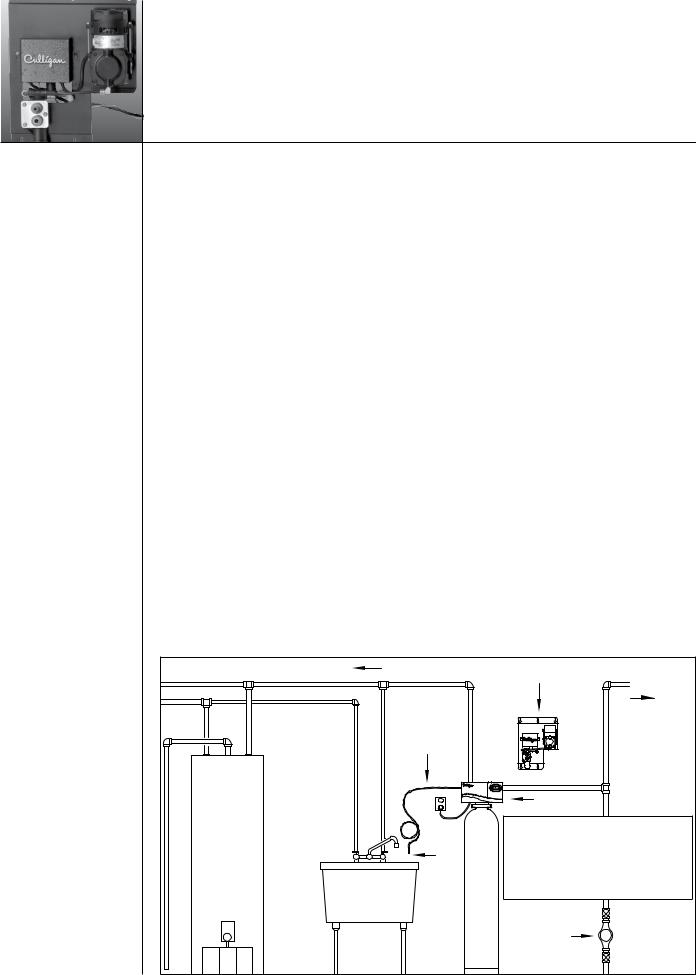
Filtered Water
Drain
Line
Water
Heater
Air
Gap
Wall Mounted
Aeration Assemby
To
Hose Bibs
Unfiltered
Water
|
Note: Waste connections or drain |
|
outlets shall be designed and |
|
constructed to provide for connection |
|
to the sanitary waste system through |
|
an air gap of 2 pipe diameters or |
Filter |
25.4 mm (1 in.) whichever is larger. |
|
|
|
Water |
|
Meter |
Figure 1

Power Loss |
Familiarization |
The Circuit board is equipped with a Hi-Cap Capacitor and EEPROM memory chip. The capacitor is capable of maintaining the time, for at least two days, in the event of a power outage. The EEPROM ensures that the individual programming parameters of your filter are not lost.
If the power outage lasts long enough to drain the Hi-Cap Capacitor, the control will flash “12:00 PM” when power is returned to the control. The unit will continue to keep time from the moment power is restored, and will initiate a full regeneration at the preset regeneration time. The time of day will need to be reset in order to return the regeneration to its preset time.
If you live in an area where power outages occur with a regular frequency, a battery backup option is available for ensuring that the time of day is properly maintained. Contact your Culligan Dealer for more information.
Regeneration
To initiate a regeneration at the preset time, press the “REGEN” button. The “REG” light will light. To initiate an immediate regenertion, press and hold the “REGEN” button for at least five seconds. The “REG” will light and blink. An immediate regenertion will also occur if a power outage has lasted for more than four hours and the Immediate Regenertion option is chosen. Ask your Culligan Dealer about this feature.
A regeneration at the Time of Regeneration will occur if so signaled by the Soft-Minder meter. The “REG” enunciator on the display will also be lit.
Service
Culligan’s Sulfur-Cleer™ water filter is equipped with a self diagnostic program to insure optimal operation of your water filter. Should service become necessary, a phone icon will appear in the display. If this condition occurs, call your local Culligan Dealer for assistance. The phone icon and error code will be the only items displayed when service is required on the control.
 Loading...