


CDK4242P-A
CDK4242P-A
High Denition DVR
Surveillance System

Chapter 1 Product Overview
1.1 Rear Panel
Chapter 2 DVR Installation & Connection
2.2 Connection Diagram
2.3 Power Supply Connection
Chapter 3 DVR Common Operations
3.1 Using the Supplied Mouse
3.2 Using the Virtual Keyboard
3.3 Password
Chapter 4 DVR Starting up
4.1 Start Wizard
4.1.1 Start Wizard
4.1.2 Network Configuration
4.1.3 Date/Time
4.1.4 IP Camera
4.1.5 Disk
4.1.6 Resolution
4.1.7 Mobile
4.1.8 Summary
4.2 Live View Screen Overview
4.2.1 Camera Quick Toolbar
4.2.2 Taskbar
4.2.3 Start Menu
4.2.3.1 Unlock and Lock Screen
4.2.3.2 Shutdown
Chapter 5 DVR System Setup
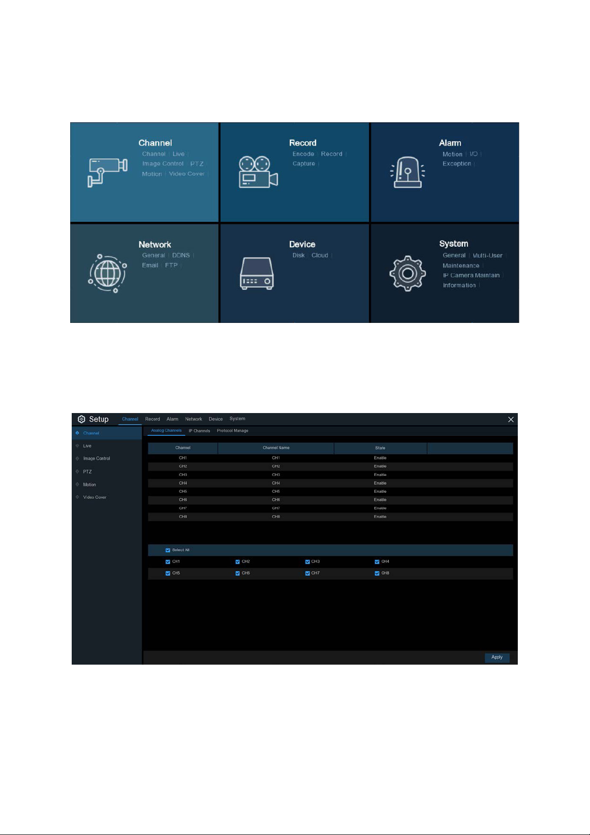
5.1 Channel
5.1.1 Channel
5.1.1.1 Analogue Channels
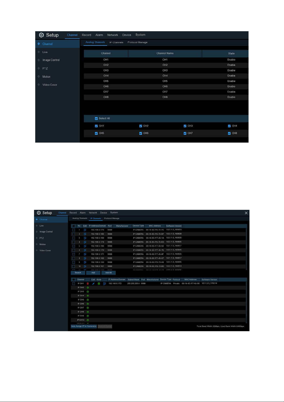
5.1.1.2 IP Channels
5.1.1.3 Protocol Manage
5.1.2 Live
5.1.3 Image Control
5.1.4 PTZ
5.1.4.1 PTZ control
5.1.5 Motion
2

5.1.6 PIR
5.1.7 Video Cover
5.2 Record
5.2.1 Encode
5.2.2 Record
5.2.2.1 Record
5.2.2.2 Record Schedule
5.2.3 Capture
5.2.3.1 Capture
5.2.3.2 Capture Schedule
5.3 Alarm
5.3.1 Motion
5.3.2 I/O
5.3.3 PIR
5.3.4 PTZ Linkage
5.3.5 Exception
5.4 Network
5.4.1 General
5.4.4.1 PPPoE
5.4.1.2 3G
5.4.1.3 Port Configuration
5.4.2 DDNS
5.4.3 Email
5.4.3.1 Email Configuration
5.4.3.2 Email Schedule
5.4.4 FTP
3

5.5 Device
5.5.1 Disk
5.5.1.1 S.M.A.R.T
5.5.2 Cloud
5.6 System
5.6.1 General
5.6.1.1 Date and Time
5.6.1.2 NTP Settings
5.6.1.3 DST Settings
5.6.2 Output Configuration
5.6.2.1 LIVE-OUT
5.6.3 Multi-user
5.6.3.1 Changing Password
5.6.3.2 Add New Users
5.6.3.3 Setting User Permissions
5.6.4 Maintenance
5.6.4.1 Log
5.6.4.2 Load Default
5.6.4.3 Upgrade
5.6.4.4 Parameter Management
5.6.4.4 Auto Reboot
5.6.5 IP Camera Maintain
5.6.5.1 Upgrade IP Camera
5.6.5.2 Load Default Settings for IP Camera
5.6.6 System Information
5.6.6.1 Information
5.6.6.2 Channel Information
5.6.6.3 Record Information
5.6.6.4 Network State
6.1.5.1 Picture Preview Control

Chapter 6 Search, Playback & Backup
6.1 Using Search Function
6.1.1 Search & Play Video in General
6.1.1.1 Video Clip Backup
6.1.2 Event Search, Playback & Backup
6.1.2.1 Event Playback Control
6.1.3 Sub-periods Playback
6.1.4 Smart Search & Playback
6.1.4.1 Smart Search Area
6.1.5 Picture Search & View
Chapter 7 Remote Access via Web Client
7.1 Basic System Environment Requirements
7.2 Web Plugin Download and Installation.
7.2 Web Plugin Download and Installation.
7.3 Web Client Manager
7.3.1 Live Interface
7.3.2 Playback .
7.3.2.1 Playback Control Buttons
7.3.3 Remote Setting
7.3.4 Local Setting
Chapter 8 Viewing Backed Up Video on PC/Mac
Chapter 9 Remote Access via Mobile Devices
Chapter 10 Appendix
10.1 Troubleshooting
10.2 Usage Maintenance
10.3 Accessories (For reference only)

Safety Precautions
Please carefully read the following safety precautions so as to avoid personal injuries and prevent the equipment and
other connection devices from being damaged.
1. Power supply
Never operate the equipment with any power supply other than the one supplied in the box.
2. Never push objects of any kind through the openings of the DVR
Never push objects of any kind through any openings of the DVR to avoid electric shock or damage to your DVR.
3. Do not place the DVR in a dusty environment
Dust could affect the connections and damage the electronics.
4. Do not place the DVR in a wet or humid environment
Do not position the DVR in a location that is likely to get wet or humid such as outdoors or in a basement. If the DVR
comes into contact with water, unplug the power cable immediately and contact your local dealer.
5. Keep the surface of the equipment clean and dry
Use a soft slightly damp cloth to clean the outer case of DVR and make sure it is dried straight away (do not use
liquid aerosol cleaners).
6. Do not operate if you notice any unusual problems
If you notice any strange smells, sounds or smoke coming from your DVR, unplug the power cable immediately and
contact an authorised dealer or service centre.
7. Do not try to remove the upper cover
Warning: Do not remove the cover of your DVR to avoid electric shock or damage to the electronics.
8. Handle with care
If your DVR does not work normally after dropping it or being hit by a hard object, disconnect the power immediately
and contact an authorised dealer or service centre.
9. Position the equipment in a place with good ventilation
The DVR system includes a HDD, which can produce a significant amount of heat during normal operation. As a
result, do not block the ventilation openings (on the top, bottom, both sides and the reverse side) for cooling the
system during operation. Make sure your DVR is kept in a well ventilated area and that the cables are kept tidy and
do not obstruct air flow.
10. The included power supply can only be used for one DVR system, do not connect more equipment to the
power supply, it will not have enough power to operate correctly.
11. Do not place objects containing water, such as a flower vase, on or near the equipment.
6
Chapter 1 Product Overview
1.1 Rear Panel
Video Inputs HDMI Output Ethernet Power
Audio Output
Audio Output Connect to an amplifier or active speakers. RCA connection.
Video Inputs Camera video inputs. BNC connection.
Audio Inputs Microphone inputs for third-party cameras that have built-in microphones. RCA Connection.
HDMI Output Connect to your TV or monitor’s HDMI input using the supplied HDMI cable.
VGA Ouptut Connect to your TV or monitor if it doesn’t have a HDMI input.
Ethernet/LAN Connect to your network router using supplied RJ45 Ethernet cable.
USB Port Connect the supplied mouse or external USB Hard Drive.
RS485/PTZ Connect to third-party cameras that have a Pan-Tilt-Zoom function
POWER Connect to the supplied mains power adaptor
VGA Output USB Port PTZAudio Inputs
7
2.2 Connection Diagram
Network Router
Microphones
(Supplied cameras do not
include microphones)
(Not included)
Mains Power
Adaptor
Amplifier/Active Speakers
(Not included)
Analogue
(AHD) Cameras
USB Thumb
Drive or HDD
(Not included)
HDMI or VGA connection to your HDTV
or Monitor (HDMI Lead included).
PTZ Control
(Camera not included)
Note:
The above diagram is for reference purposes only, and uses a 4 channel DVR for the example.
Your connections and setup may differ from this description.
2.3 Power Supply Connection
A mains power adaptor is included in the kit. Plug the adaptor into an available mains power outlet and the other end
into the power socket on the back of the DVR.
8
Chapter 3 DVR Common Operations
3.1 Using the Supplied Mouse
1 2
3
A USB Mouse is supplied to navigate the on-screen menus. Plug the mouse into an available USB port on the front or
back of the DVR.
1. Left Button:
• Click to select menu options.
• During live viewing in split-screen view, double-click on a channel to view it in full-screen. Double-click the
channel again to return to split-screen viewing.
• Click on a channel on Live Viewing screen to open Camera Quick Toolbar.
• Click and hold to drag sliders and scales on menu mode
2. Right Button:
• Click once to open the Taskbar on the Live Viewing screen. View Taskbar on 4.2.2 Taskbar
• In menus, click to go back / close menus.
3. Scroll Wheel:
• In menus, scroll to move up / down through the menu content.
• While hovering over the volume control wheel, scroll to turn system volume up / down.
3.2 Using the Virtual Keyboard
A virtual keyboard will automatically appear on the screen when you need to enter data.
Use the mouse to operate this keyboard.
Click to toggle the keyboard to
upper case and more punctuation
Click to delete
a character
Move the cursor to right
Move the cursor to left
Click to complete
the enter
9
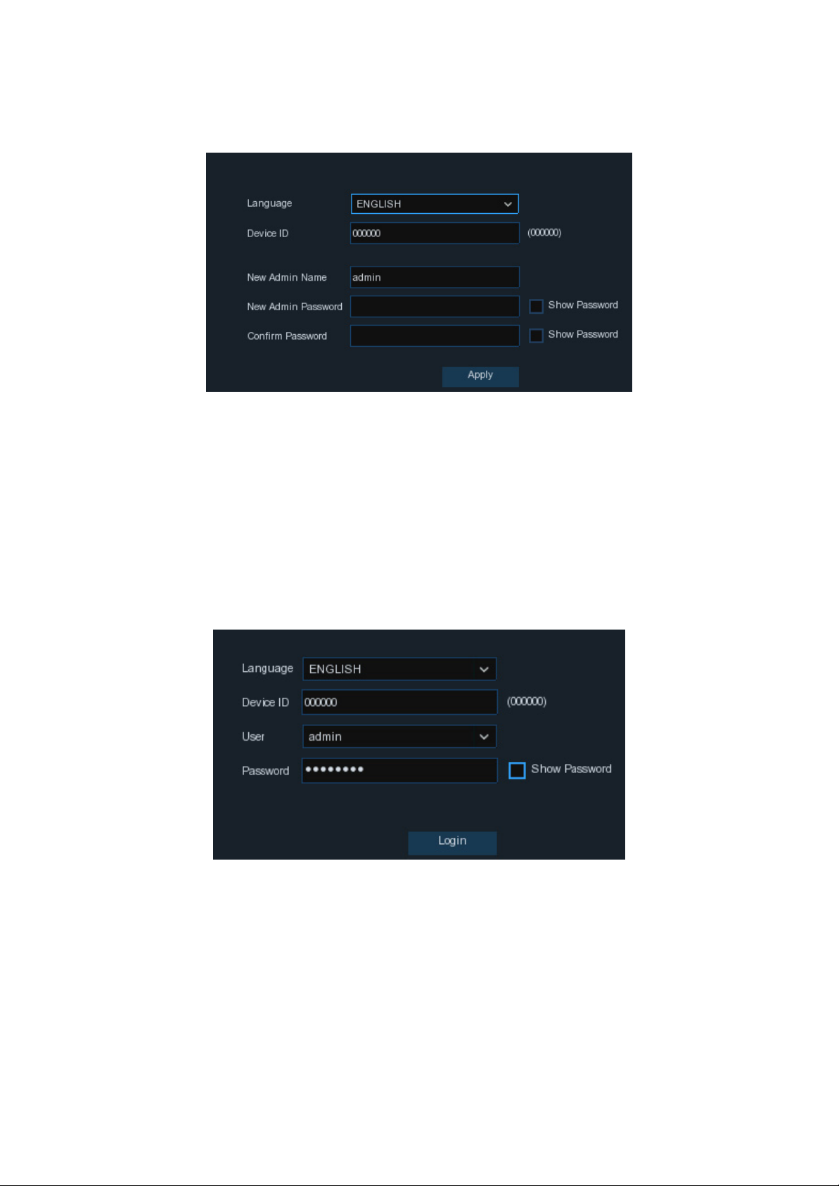
3.3 Password
The first time you run the DVR, you will be asked to set your own password, which is important to help protect your
privacy. You can also change the Admin username for extra security. You may want to write down your username
and password in a safe place in case you forget them in the future.
Language: Choose your preferred language to be shown on-screen.
Device ID: Input the device ID shown in the parentheses (). Default ID is 000000.
View more about Device ID on 5.6.1 General further within this manual.
New Admin name: To set your own administrator name.
New Admin Password: To set your own password. The password must be a combination of 8 characters.
Confirm Password: Enter your own password again.
Click Apply to confirm your settings you will then be taken to the login interface. Enter your user name & password
to Login.
NOTE: If you forget your password, you will be unable to login to the system. You will need to contact Concord to
reset the password if you are locked out. Visit: www.concord.support.
10
Chapter 4 DVR Starting up
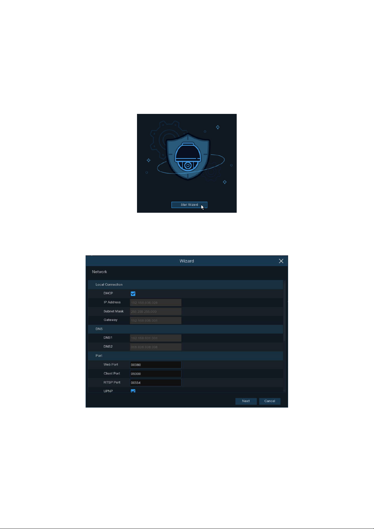
4.1 Start Wizard
The Startup Wizard will help configure the system and get the DVR working quickly.
4.1.1 Start Wizard
Click the Start Wizard to proceed to the next step
4.1.2 Network Conguration
If you have connected your DVR to your network, the DVR will need to identify itself on the network with an IP
address. In most cases, you will be able to simply tick the DHCP box so your network router automatically assigns
the IP Address.
If your network requires you to manually assign an IP address you will need to perform the steps on the next page.
11
IP Address: The IP address identifies the DVR in the network. It consists of four groups of numbers
between 0 to 255, separated by periods. For example, “192.168.001.100”.
Subnet Mask: Subnet mask is a network parameter which defines a range of IP addresses that can be used in a
network. If IP address is like a street where you live then subnet mask is like a neighbourhood. The subnet address
also consists of four groups of numbers, separated by periods. For example, “255.255.000.000”.
Gateway: This address allows the DVR to access the Internet. The format of the Gateway address is the same
as the IP Address. For example, “192.168.001.001”.
DNS1/DNS2: DNS1 is the primary DNS server and DNS2 is a backup DNS server. Usually, it should be enough just to
enter the DNS1 server address. You will need to consult your Internet Service Provided (ISP) for these details if you
do not know how to find them yourself.
Port
Web Port: This is the port that you will use to log in remotely to the DVR (e.g. using the Web Client).
If the default port 80 is already taken by other applications, please change it.
Client Port: This is the port that the DVR will use to send information through (e.g. using the mobile app).
If the default port 9000 is already taken by other applications, please change it.
RTSP Port: This is the port that the DVR will be allowed to transmit real-time streaming to other device (e.g. using a
streaming Media player.).
UPNP: If you want to log in remotely to the DVR using Web Client, you need to complete the port forwarding in
your router. Enable this option if your router supports the UPnP. In this case, you do not need to configure manually
port forwarding on your router. If your router does not support UPnP, make sure the port forwarding is completed
manually in your router.
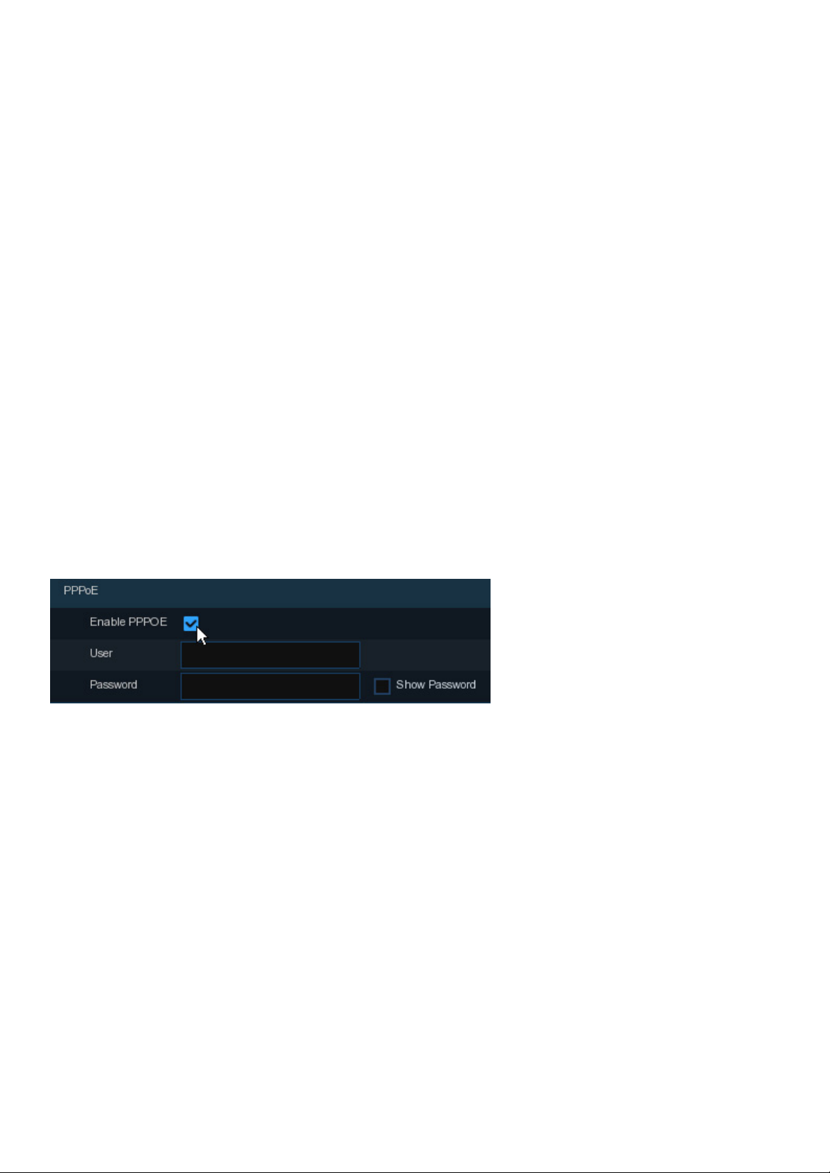
PPPoE
This is an advanced protocol that allows the DVR to connect to the network more directly via DSL modem.
Check the “Enable PPPOE” box, and then enter the User name & Password of the PPPoE.
3G
You need to connect a 3G dongle to the DVR.
Enable the 3G option, enter the APN, Dial Code, User name & password according to the instruction of your 3G
service.
12
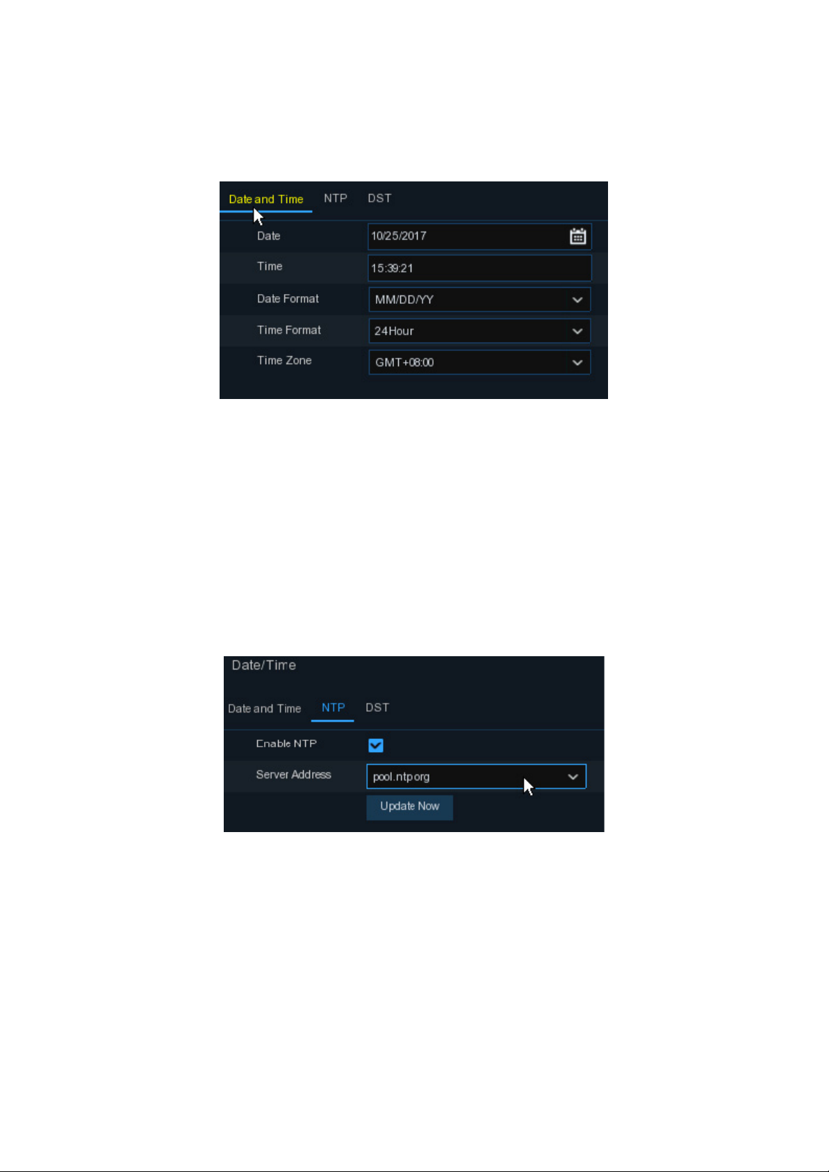
4.1.3 Date/Time
This menu allows you to configure the Date, Time, Date Format, Time Format, Time Zone, NTP and DST.
Date and Time
Click on the calendar icon to set the current system date.
Date: Click on the calendar icon to set the system date.
Time: Click to set the system time.
Date Format: Choose from the dropdown menu to set preferred date format.
Time Format: Choose time format between 24Hour and 12Hour.
Time Zone: Set the correct time zone
NTP
NTP stands for Network Time Protocol. This feature allows you to synchronise the date and time automatically on the
DVR over Internet. Therefore, the DVR needs to be connected to the Internet.
Check the “NTP” box, and select the NTP server.
13
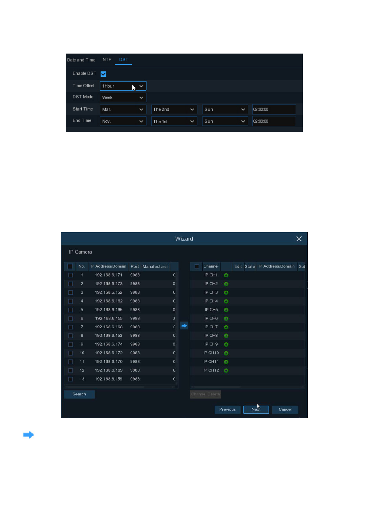
DST
DST stands for Daylight Savings Time.
DST: Enable if Daylight Saving Time (DST) is observed in your region
Time Offset: Select the amount of time to offset for DST
Time Mode: Choose to set the daylight saving time in weeks or in days
Start Time/End Time: Set the start time and end time for daylight saving
4.1.4 IP Camera
This DVR can also support two IP Cameras (Not included) connected to your network. This menu allows you to add
up to two IP cameras to the DVR. (Note: example shown here is for a 12 channel DVR)
Click Search to search IP cameras in the same network. Choose the IP camera(s) you want to add, and then click
icon to add to the DVR.
14
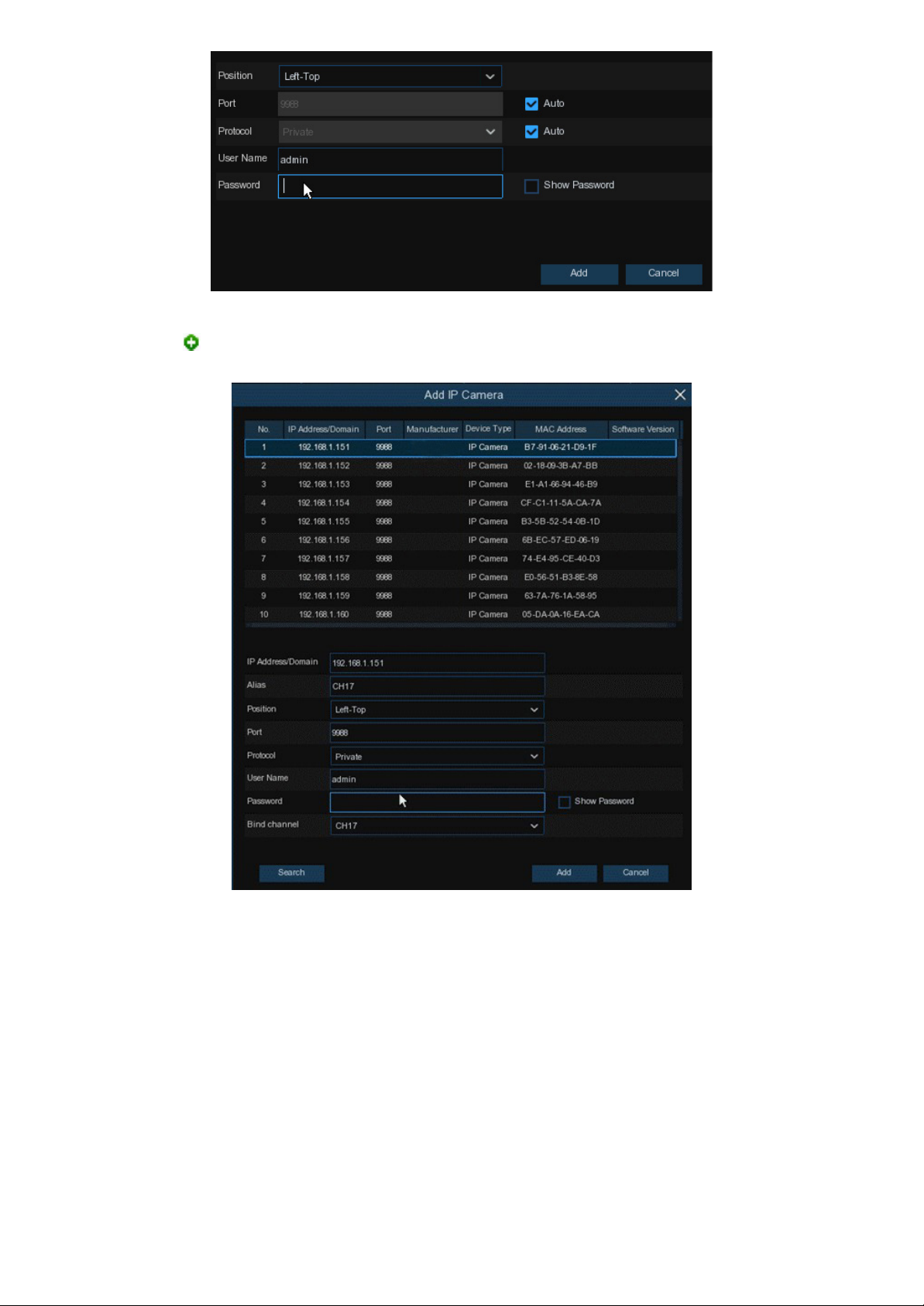
Enter the camera’s user name & password to add the camera(s).
You can also click button to add individual IP cameras to a single channel.
Click Search button to search IP cameras, and then click one of the IP camera in the device list.
IP Address/Domain: IP address or domain name of the IP camera
Alias: Name of the IP camera
Position: Position to display the camera name on the screen.
Port: Port of the IP camera
Protocol: Choose the protocol of the IP camera from the dropdown menu
User Name: Username of the IP camera
Password: Password of the IP camera
Bind channel: Choose a channel of the DVR you want to attach to.
15
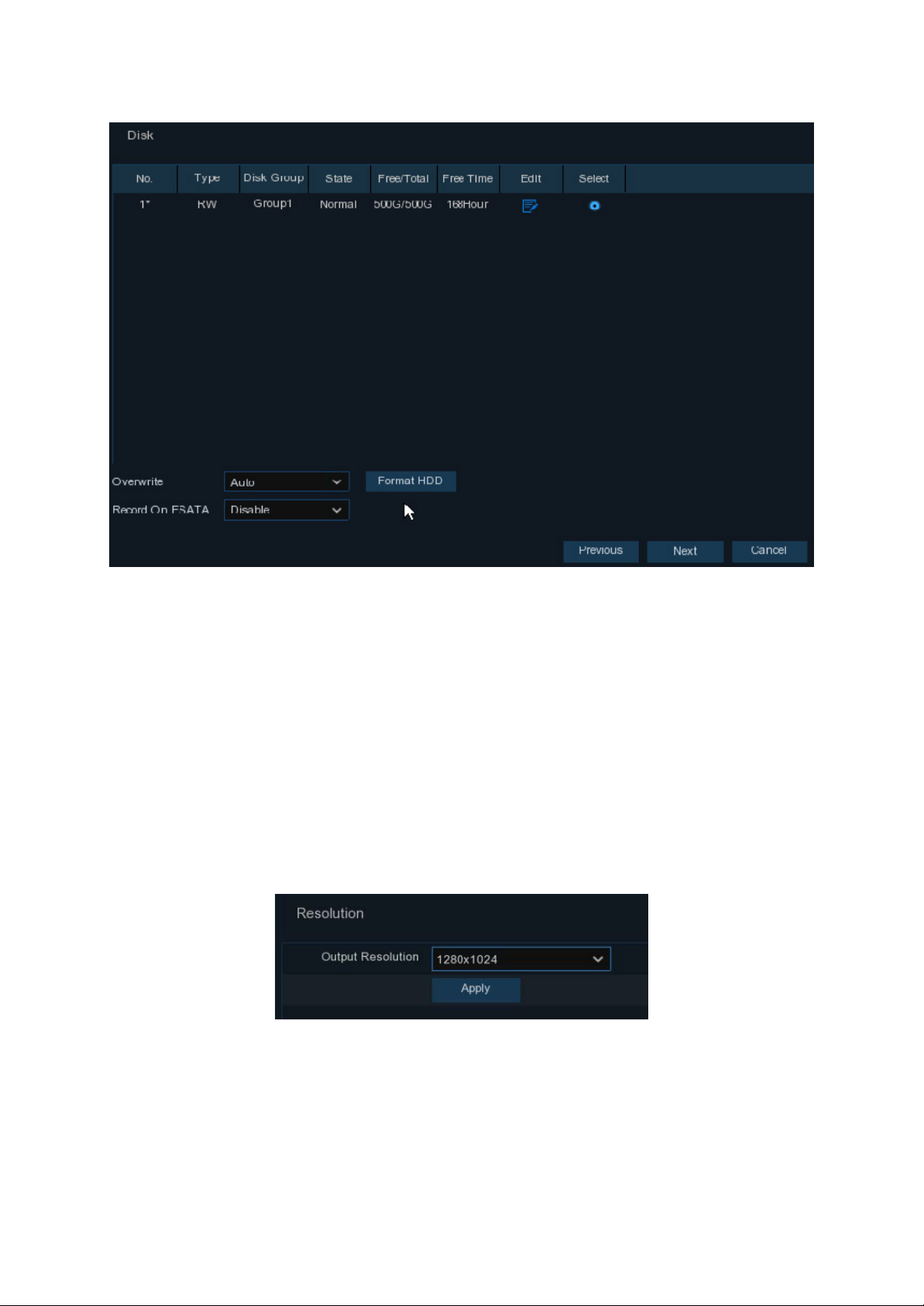
4.1.5 Hard Drive
This DVR is supplied with a hard drive already installed.
Overwrite: Use this option to overwrite the old recordings on the HDD when the HDD is full. For example, if you
choose the option 7 days then only the last 7 days recordings are kept on the HDD. To prevent overwriting any old
recordings, select Disable. If you have disabled this function, please check the HDD status regularly, to make sure the
HDD is not full.
4.1.6 Resolution
Choose an output resolution that best suits the HDTV or monitor you are connecting to.
Note: When the DVR system is starting up, it will automatically match the best resolution of your monitor.
16
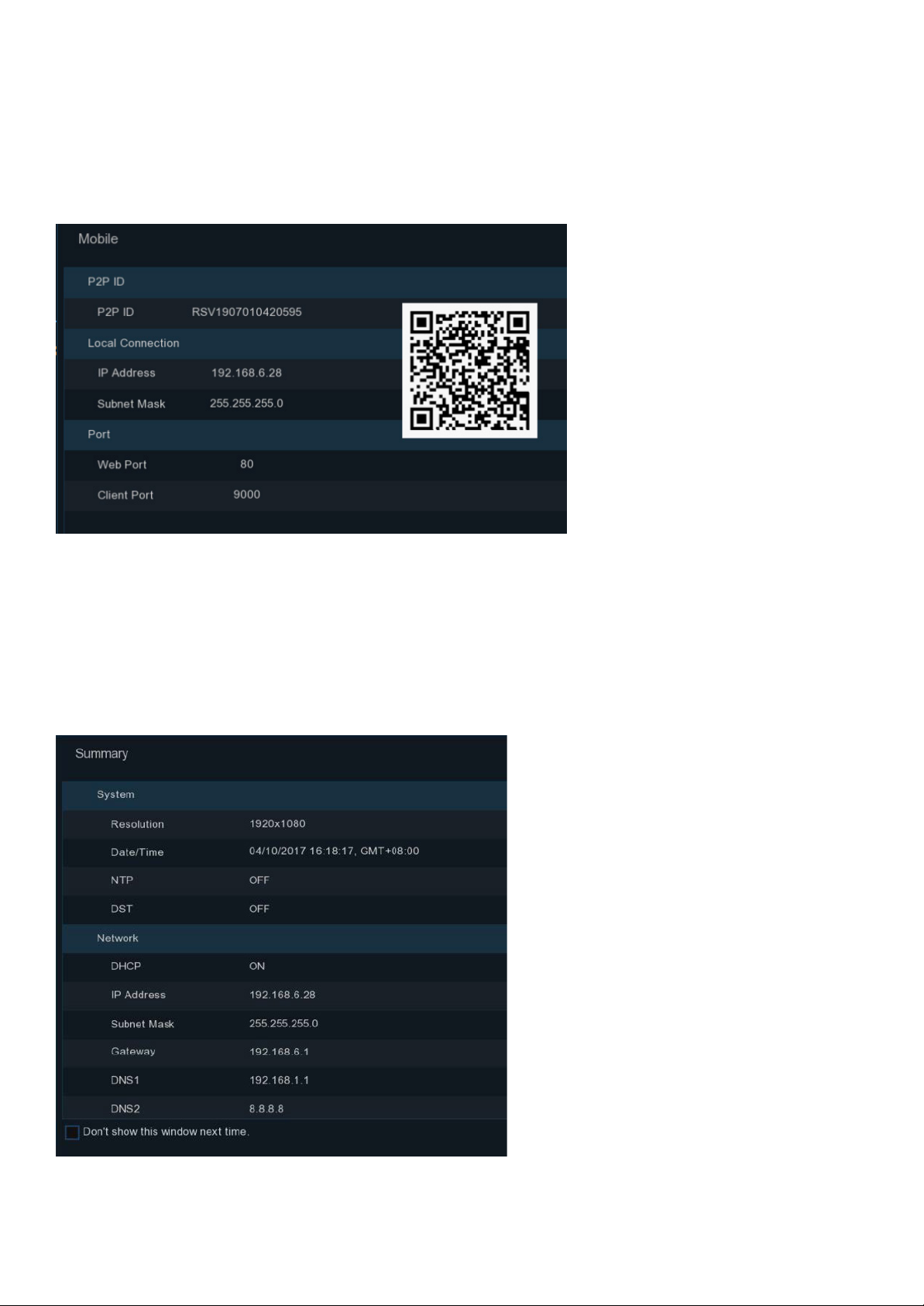
4.1.7 Mobile
You can access this DVR remotely from your Smartphone or Tablet, providing you have the DVR connected to the
network with Internet access.
The P2P (Peer to peer) ID makes it easy to connect a Smart device. Once you have the app installed in your
Smartphone or Tablet you scan this QR code and follow the instructions in the app to complete the setup.
4.1.8 Summary
You can check the system summary information you had set in the start wizard and finish the wizard.
Tick “Don’t show this window next time” if you don’t want to display the start wizard when your DVR system
reboots. Click Finish button to save & exit.
17
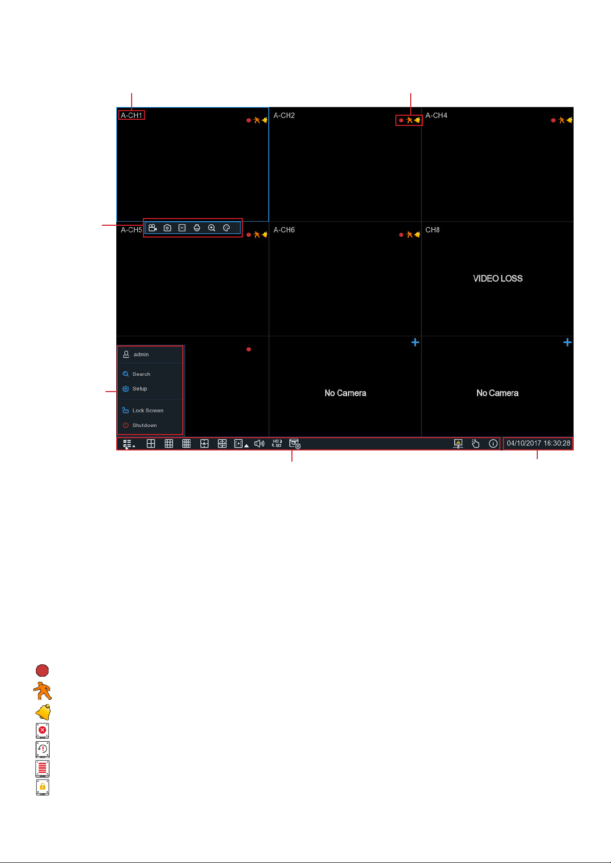
4.2 Live Viewing Screen
Camera Title Status Icons
Camera Quick
Toolbar
Start Menu
Task Menu Bar
Camera Title
The camera title indicates the type of camera connected. This DVR is supplied with AHD cameras.
A-: This indicates that the camera connected is an AHD camera
IP: This indicates that the camera connected is an IP camera
Status Icon
This indicates that the DVR is currently recording.
System Date & Time
This icon appears when the camera has detected motion.
The icon indicates that the external I/O alarm device is triggered.
This icon indicates that the HDD is in error.
This icon indicates the HDD is unformatted.
This icon indicates the HDD is full.
This icon indicates the HDD is read-only.
18
Signal Lost: The analogue camera is disconnected.
No Camera: IP camera is disconnected.
Decoding Failed: The DVR doesn’t support this kind of IP camera compression standard, please change to H.264
compression standard.
Click to open Quick Add menu to add IP camera
Click to edit current IP camera
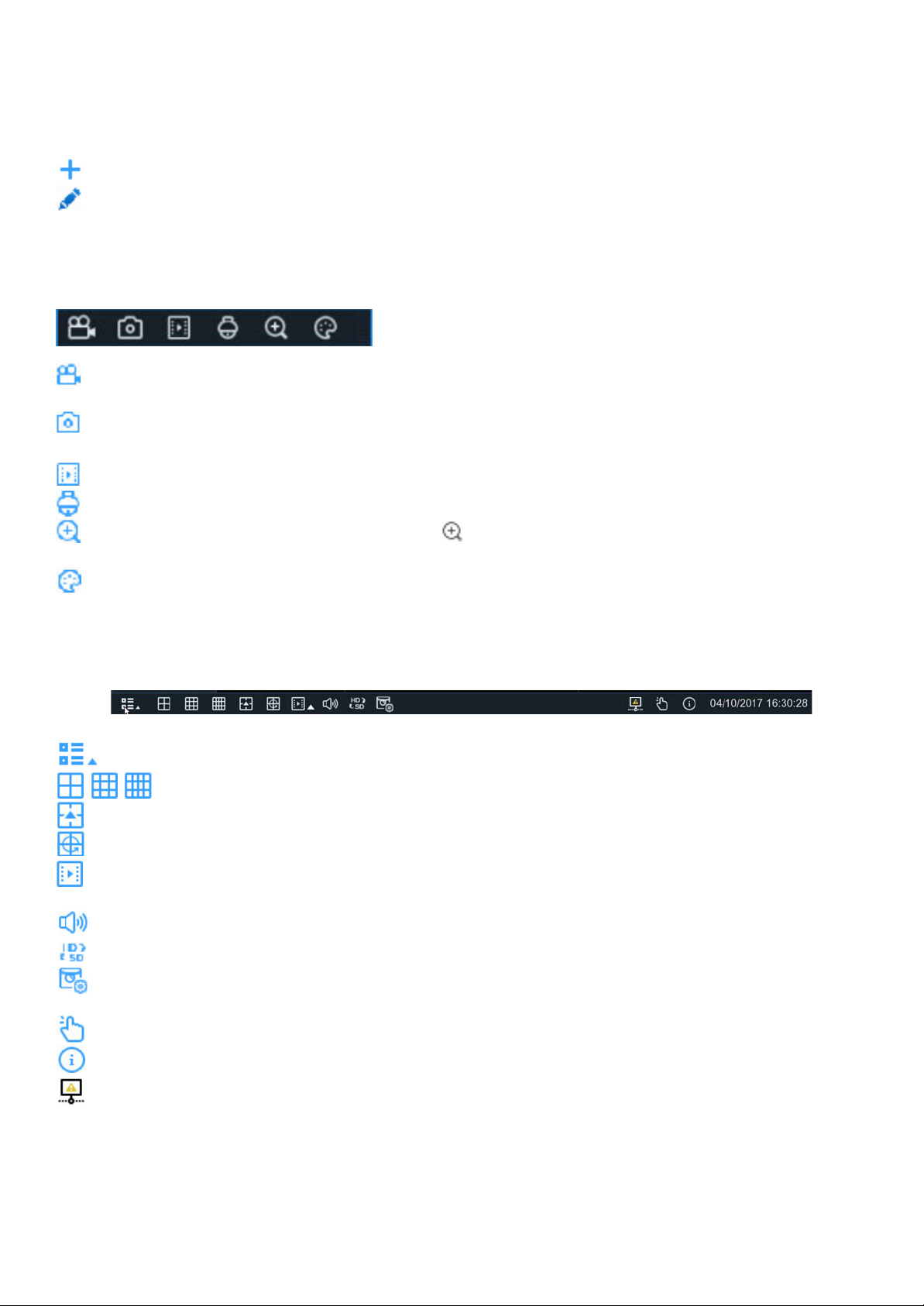
4.2.1 Camera Quick Toolbar
In live viewing, click the left button of your mouse on a connected camera to display the Camera Quick Toolbar.
Click to manually record the channel immediately. If manual recording is in progress, the icon will be red. Click
one more time to stop manual recording.
Click to save a snapshot of the current camera image. Manual Capture must be enabled to use this feature.
For details on enabling Manual Capture, see 5.2.3.1 Capture.
Click to play the latest 5 minutes recording of this channel
Click to enter PTZ control panel
Click to zoom in on the selected channel. When the icon appears, press and hold the left button of your
mouse to drag the area you want to zoom in.
Click to adjust the colour settings of the channel. You can adjust the HUE, BRIGHT, CONTRAST & SATURATION of
the image.
4.2.2 Taskbar
Click to open the Start Menu
Click to choose different layouts for live view
Click to choose more layouts for live view
Click to start viewing channels in a sequence
Quick playback. You can choose to play the latest recording for all channels from the beginning of the day, or
you can choose the playback from the last 5s, 10s, 30s, 1Min, 5Min.
Click to adjust audio volume
Click to switch all IP channels between mainstream and substream (for live view resolution)
Click to switch among real-time, balanced, or smooth view. The view effect modes affect only the live view
video quality by bitrate and frame rate but do not affect the recording quality.
To start or stop Manual Record and Manual Alarm.
To view system information, channel information, record info and network state.
This icon will appear if the network is disconnected.
19
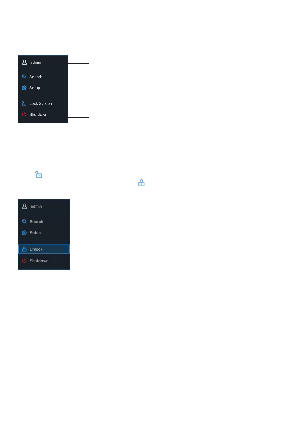
4.2.3 Start Menu
With the start menu, you can switch user, search & playback, enter system setup menu, lock & unlock the screen,
shut down, reboot & logout of the system.
To switch users. To enable multi-user read 5.6.3 Multi-User.
Search & Playback. To learn more, read Chapter 6 Search, Playback & Backup.
System Setup. To learn more read Chapter 5 DVR System.
Lock & Unlock Screen.
To learn more read
Shutdown, reboot & logout of the system. Learn more by reading
4.2.3.2 Shutdown.
4.2.3.1 Unlock and Lock Screen
below.
4.2.3.1 Unlock and Lock Screen
The screen will automatically lock after 1 minute of inactivity to prevent unauthorised access.
If necessary, you can also lock the screen operation manually. To do so, go to Start Menu, and then click the Lock
Screen icon to lock the system immediately.
If the system is locked, you can click the Unlock icon to unlock the system for further operation.
20
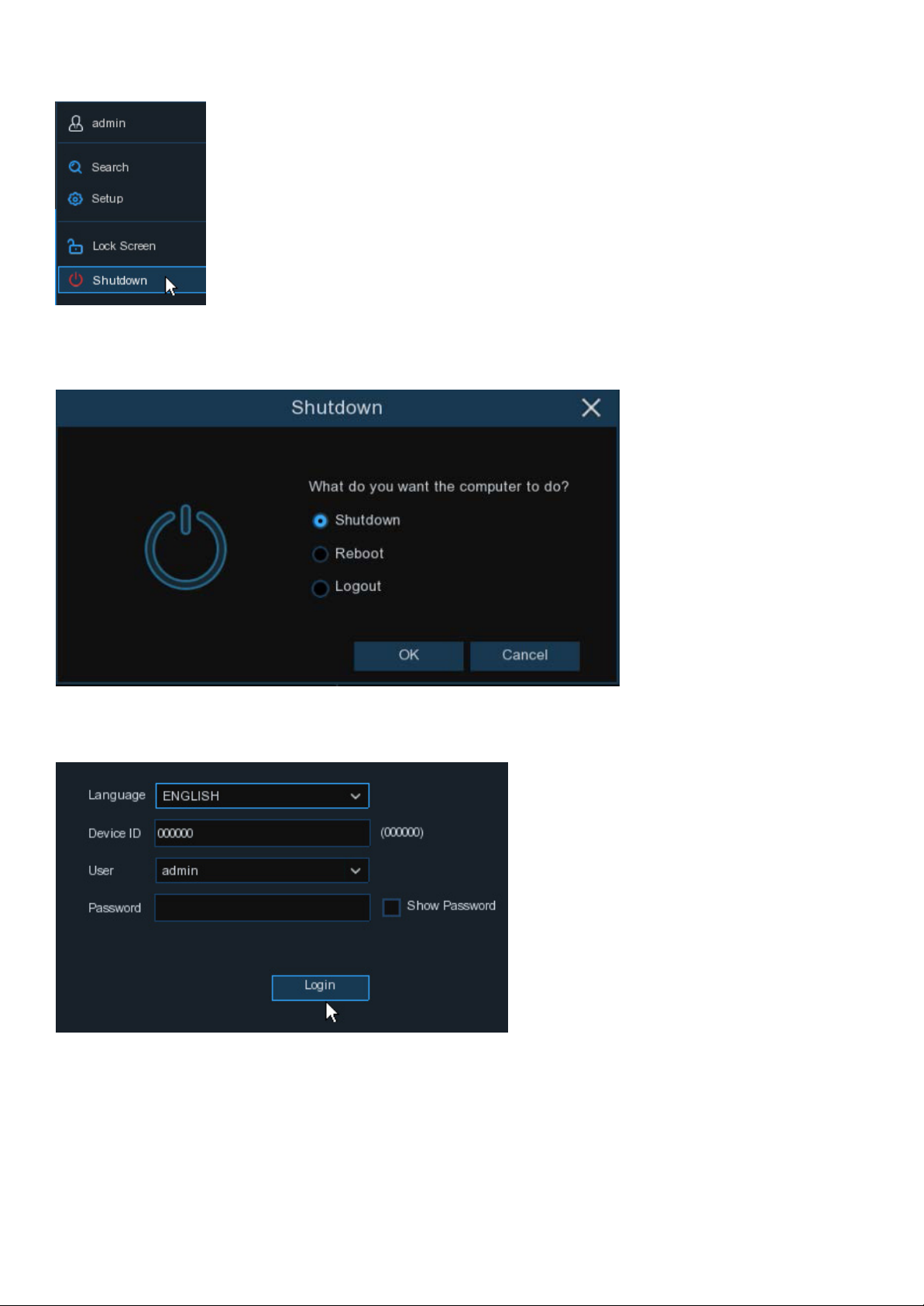
4.2.3.2 Shutdown
Click the Shutdown button from Start Menu, and select the Shutdown, Reboot or Logout action you want to
perform, then click the OK button. The system may require you to enter the Admin password to authenticate.
If you choose Logout, the live viewing screen will no longer be visible.
You will need to log into the system for further operations.
21
Chapter 5: DVR System Setup
You are able to configure the DVR for Channel, Record, Alarm, Network, Device & System from Start Menu > Setup.
5.1 Channel
In this section, you can configure the camera, live view display, manage IP cameras, adjust IP camera’s image, PTZ
setup, motion setup, convert mode, and more.
22
5.1.1 Channel
5.1.1.1 Analogue Channels
If you want to disable an analogue channel, uncheck the box and click Apply to save. Disabling analogue channels
can free up channels for more IP cameras. To do so, you need to enable the XVR mode in advance at System >
General > Mode, view more on 5.6.1 General.
5.1.1.2 IP Channels
If you enable the XVR mode for the DVR, it supports to add IP cameras & modify IP channels.
(Note: 8 channel system shown)
Click Search to search IP cameras from local network, click Add to add an individual IP camera, click Add All to add
all IP cameras.
23
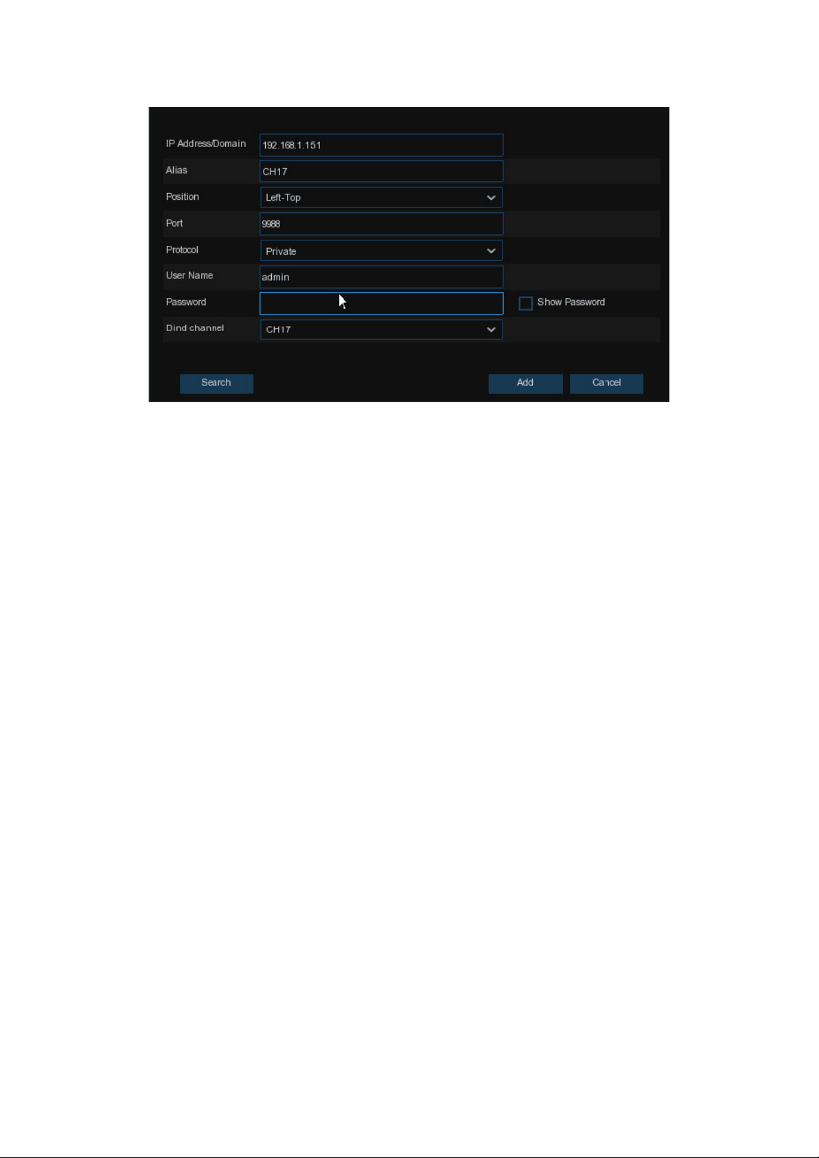
Click Search button to search for IP cameras, and then click one of the IP camera in the device list.
IP Address/Domain: IP address or domain name of the IP camera
Alias: Name of the IP camera
Position: Position to display the camera name on the screen.
Port: Port of the IP camera
Protocol: Choose the protocol of the IP camera from the dropdown menu
User Name: User Name of the IP camera
Password: Password of the IP camera
Bind channel: Choose a channel of the DVR you want to attach to
Auto Assign IP to Camera(s): The added IP camera would be not able to connect if its IP address is not in the same
network segment with DVR. This function will reassign an IP address to all added IP cameras.
Channel Delete: Choose one or more added IP cameras, and click this button to delete.
24
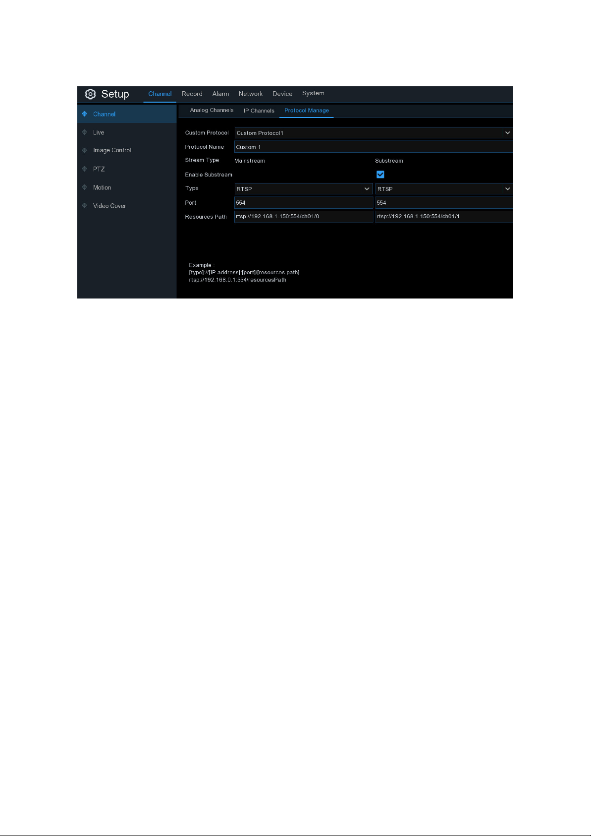
5.1.1.3 Protocol Manage
With the Protocol Manage, you can edit your own RTSP protocol for IP camera connection.
Custom Protocol: The system supports up to 10 custom protocol options.
Protocol Name: To give a name to your custom protocol.
Enable Substrearm: Check the box if you want to enable sub-stream.
Type: Only RTSP available now.
Port: Input the RTSP port of your IP camera.
Resources Path: Input the RTSP address of your IP camera.
25
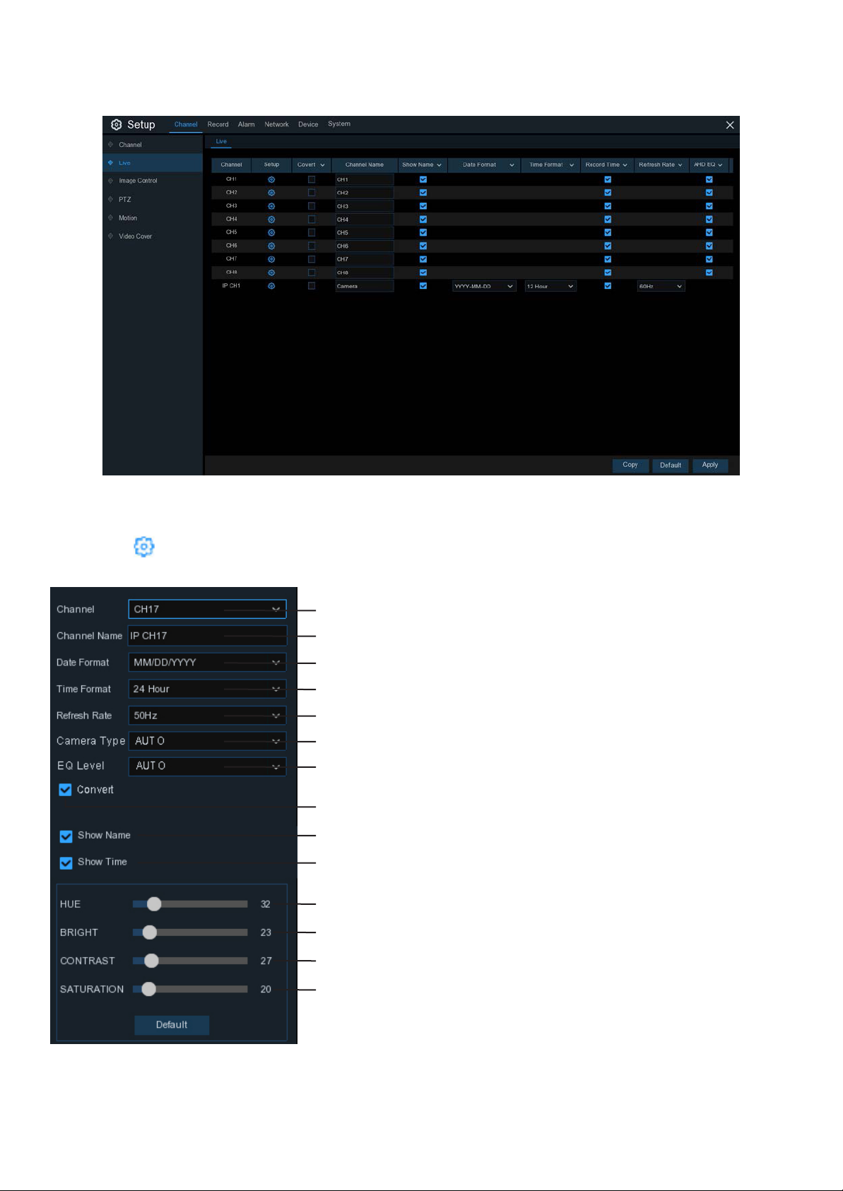
5.1.2. Live
To configure camera parameters.
Channel: Display channel number.
Setup: Click icon to open the setup page.
Choose a channel to configure
Give a name to the camera
Date format to display for the camera (for IP camera only)
Time format to display for the camera (for IP camera only)
Refresh Rate of the camera (for IP camera only)
Choose a camera type (Auto, AHD, TVI, CVI) for analogue camera
Choose an AHD EQ (Enhanced Quality) level depends on your camera
video cable
Check the box If you want to hide the live image of this channel
To show the camera name in live view screen
To show the system time in live view screen
Adjust the Hue value for the image colour
Adjust the Bright value for the image colour
Adjust the Contrast value for the image colour
Adjust the Saturation value for the image colour
Click Default to load default settings, click Apply to save settings,
click right buttons of your mouse to exit.
26
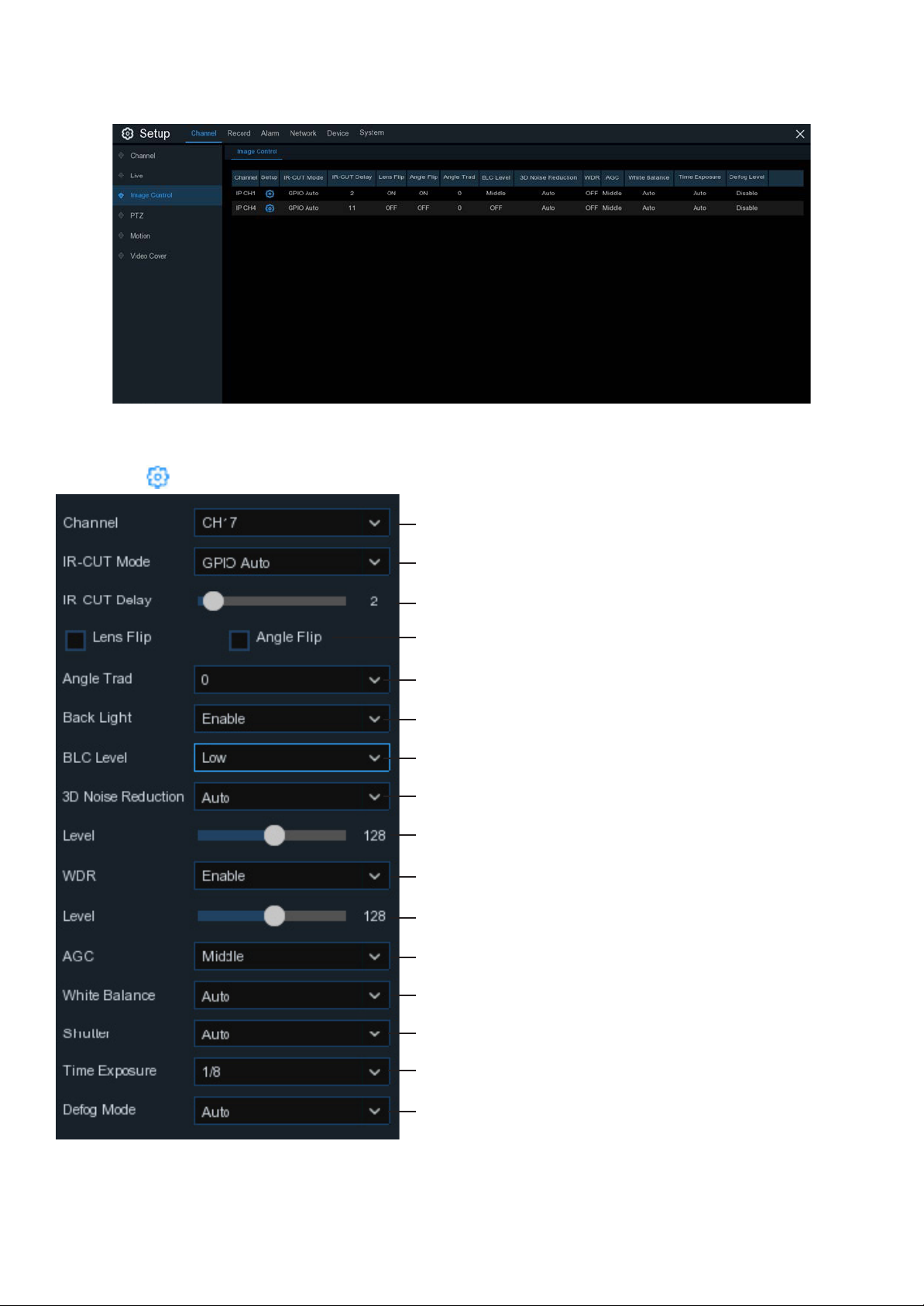
5.1.3 Image Control
This menu allows you to control image settings for supported IP cameras.
Channel: Channel name.
Setup: Click icon into the setup page.
Choose a channel to configure
Select the desired built-in IR cut filter mode to ensure the camera
works properly both in the day and night.
Set the delay time of IR-CUT switching
Check to enable lens flip and angle flip
Set the flip angle
To enable or disable Backlight compensation
Choose the backlight compensation level
To enable or disable 3D noise reduction function
Set the 3D noise reduction level
Enable to automatically adjust the brightness and contrast of the
video when shooting in darkness with bright light sources.
Set the WDR level
Automatic Gain Control
Configure white balance
Set the shutter mode
Choose the exposure time of the camera
Use in foggy environments to improve the video quality
27
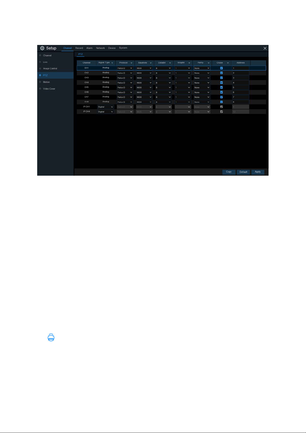
5.1.4 PTZ
This menu allows you to configure the PTZ (Pan-Tilt-Zoom) settings for a dome camera (Not included)
Channel: Channel name
Signal Type: Analog for analogue channels, Analog & Digital for IP channels.
Protocol: Choose the communication protocol between the PTZ capable camera and DVR. If your camera supports
the UTC (Up the Coax) function, you can choose COAX1 or COAX2 to display your camera OSD menu or control the
UTC PTZ function.
Baudrate: The speed of the information sent from the DVR to the PTZ-capable camera. Make sure it matches the
compatibility level of your PTZ-capable camera.
DataBit / StopBit: The information between the DVR and PTZ-capable camera is sent in individual packages. The
DataBit indicates the number of bits sent, while the EndBit indicates the end of the package and the beginning of
the next (information) package. The available parameters for DataBit are: 8, 7, 6, 5. the available parameters for the
StopBit are 1 or 2.
Parity: For error check. See the documentation of your PTZ-capable camera, to configure this setting.
Cruise: Enable to use the Cruise mode. In order to use the Cruise mode, you need to set a number of preset points.
Address: Set the command address of the PTZ system. Please be noted that each PTZ-capable camera needs a
unique address to function properly.
5.1.4.1 PTZ control
After finishing the PTZ setup, you can use the PTZ function to control your PTZ camera.
1) Click left your mouse upon a channel on Live Viewing screen to open Camera Quick Toolbar, and choose the PTZ
control icon .
28
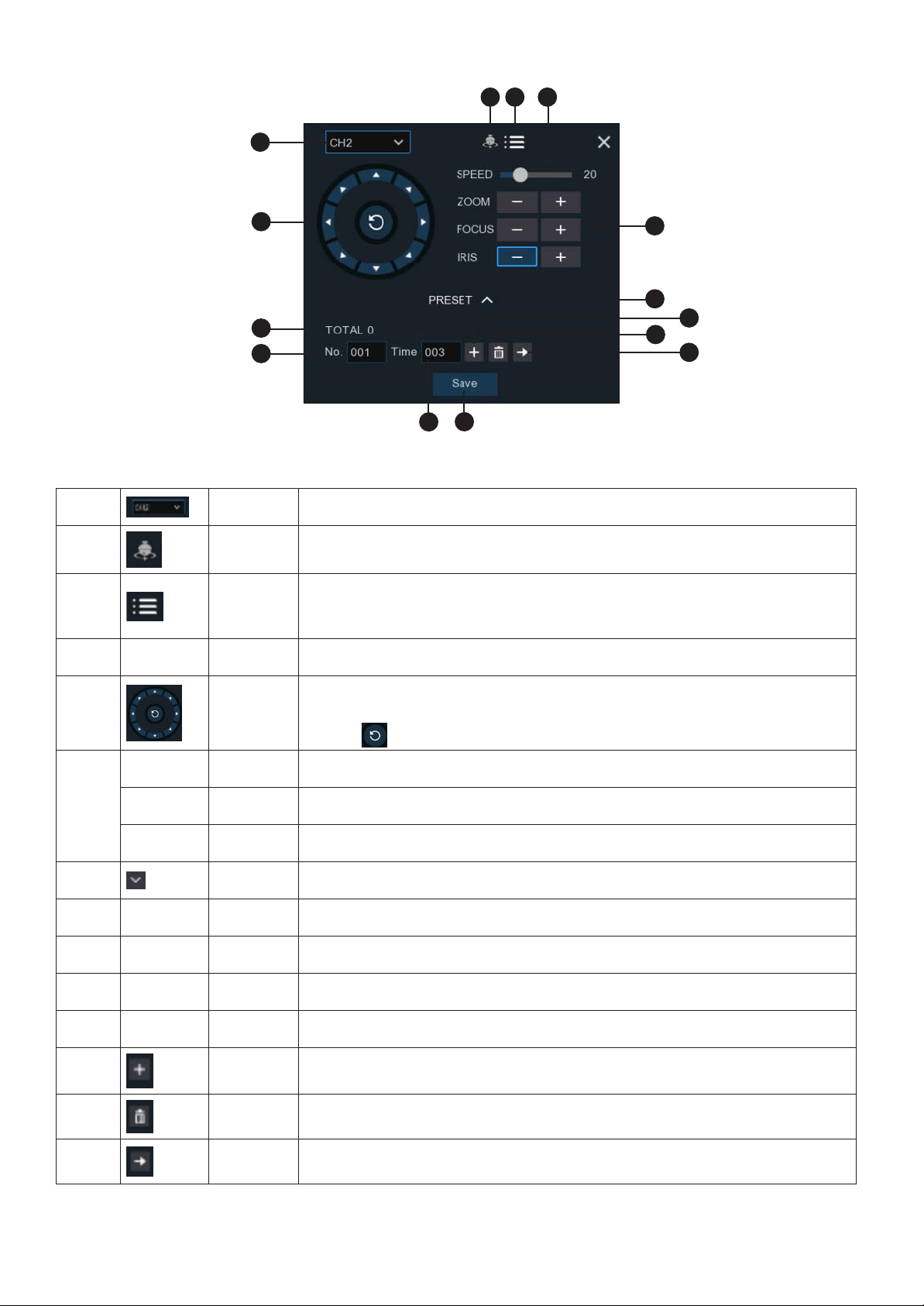
2) PTZ control panel will be displayed.
1
2
3 4
5
8
9
11
10
1 Channel Click to select the channel of the PTZ camera.
2 Cruise
3
UTC
Menu
Start / stop PTZ cruise by preset points. Make sure you had enable the Cruise
function for this channel in 5.1.4 PTZ.
If you have chosen protocol for this channel as COAX1 or COAX2, the UTC
menu button will be display. Click this icon to enter UTC OSD menu. It is also
the confirm button for your selection in the UTC OSD menu.
4 Speed Speed Adjust the PTZ speed
6
7
12
13
14
5
Pointer
Panel
A) Click the direction arrow to select the direction of the PTZ camera
B) Click up/down/left/right arrow to move cursor in UTC OSD menu
C) Click to switch to auto pan mode
- ZOOM + Zoom Click to zoom in/out.
6
- FOCUS + Focus Click to adjust the focus
- IRIS + Iris Click to adjust the iris setting
7 PRESET To display or hide the preset point panel
8 Total Total Display the total number of preset points
9 No. No. Number of preset point
10 Time Time Set the time how long the camera will stay in the preset point
11 Save Save Click to save the settings and preset points
12 set
Enter the number of a specific preset point, click this button to move your PTZ
camera to the preset point
13 Delete Click to delete the selected preset point
14 Go to
Click to set a specific preset point on a PTZ camera. You can add up to 255
preset points for the DVR.
29
 Loading...