

Comtrend NexusLink-5631 User Manual
NexusLink 5631
Wireless ADSL2+ Bonded Router
User Manual
Version C1.3, February 19, 2008
261076-005

Warning
Before servicing or disassembling this equipment, always disconnect all
power and telephone lines from the device.
Use an appropriate power supply and UL Listed telephone line cord.
Appendix D: Specifications clearly states these requirements.
Preface
This manual provides information for network administrators. It covers the
installation, operation and applications of this device. The individual reading this
manual is presumed to have a basic understanding of telecommunications.
This document is subject to change without notice. For product updates, new
product releases, manual revisions, software upgrades, etc., visit our website at
http://www.comtrend.com
.
Copyright
Copyright© 2007 Comtrend Corporation. All rights reserved. The information
contained herein is proprietary to Comtrend Corporation. No part of this document
may be translated, transcribed, reproduced, in any form, or by any means without
the prior written consent of Comtrend Corporation.
Technical support
If you find the product to be inoperable or malfunctioning, please contact a technical
support engineer for immediate service by email at INT-support@comtrend.com
Save Our Environment
This symbol means that when the equipment has reached the end of its
useful life, it must be taken to a recycling centre and processed separate
from domestic waste.
The cardboard box, the plastic contained in the packaging, and the parts that make
up this device can be recycled in accordance with regionally established regulations.
Never throw-out this electronic equipment along with your household waste.
You may be subject to penalties or sanctions under the law. Instead, ask for
instructions from your municipal government on how to correctly dispose of it.
Please be responsible and protect our environment.
1

Table of Contents
CHAPTER 1 INTRODUCTION....................................................................................................5
1.1 FEATURES........................................................................................................................................5
1.2 APPLICATION ...................................................................................................................................6
1.3 FRONT PANEL LED INDICATORS......................................................................................................7
CHAPTER 2 INSTALLATION......................................................................................................8
2.1 HARDWARE INSTALLATION ..............................................................................................................8
2.2 USB DRIVER AUTORUN INSTALLATION.........................................................................................10
2.3 USB DRIVER MANUAL INSTALLA TION (64BIT OS)........................................................................13
CHAPTER 3 WEB USER INTERFACE.....................................................................................18
3.1 TCP/IP SETTINGS ..........................................................................................................................18
3.2 LOGIN PROCEDURE........................................................................................................................19
3.3 DEFAULT SETTINGS .......................................................................................................................20
CHAPTER 4 QUICK SETUP.......................................................................................................21
4.1 AUTO QUICK SETUP.......................................................................................................................23
4.2 MANUAL QUICK SETUP .................................................................................................................24
4.2.1 PPP over ATM (PPPoA) and PPP over Ethernet (PPPoE)............................................26
4.2.2 MAC Encapsulation Routing (MER)..............................................................................31
4.2.3 IP Over ATM...................................................................................................................36
4.2.4 Bridging..........................................................................................................................40
CHAPTER 5 DEVICE INFO........................................................................................................42
5.1 WAN .............................................................................................................................................44
5.2 STATISTICS .....................................................................................................................................45
5.2.1 LAN Statistics..................................................................................................................45
5.2.2 WAN Statistics.................................................................................................................46
5.2.3 ATM statistics.................................................................................................................47
5.2.4 ADSL Statistics...............................................................................................................49
5.3 ROUTE...........................................................................................................................................51
5.4 ARP...............................................................................................................................................51
5.5 DHCP............................................................................................................................................52
CHAPTER 6 ADVANCED SETUP..............................................................................................53
6.1 WAN .............................................................................................................................................54
6.2 LAN..............................................................................................................................................55
6.3 NAT ..............................................................................................................................................56
6.3.1 Virtual Servers................................................................................................................56
2

Port Tr igger ing...............................................................................................................58
6.3.2
6.3.3 DMZ Host.......................................................................................................................59
6.3.4 ALG.................................................................................................................................60
6.4 SECURITY ......................................................................................................................................61
6.4.1 MAC Filtering.................................................................................................................61
6.4.2 IP Filtering.....................................................................................................................63
6.4.3 Parental Control.............................................................................................................66
6.5 QUALITY OF SERVICE ....................................................................................................................67
6.5.1 Queue Management Configuration ................................................................................67
6.5.2 QoS Queue Configuration..............................................................................................67
6.6 ROUTING .......................................................................................................................................70
6.6.1 Default Gateway.............................................................................................................70
6.6.2 Static Route.....................................................................................................................71
6.6.3 RIP..................................................................................................................................72
6.7 DNS..............................................................................................................................................73
6.7.1 DNS Server.....................................................................................................................73
6.7.2 Dynamic DNS.................................................................................................................73
6.8 DSL / SLAVE DSL..........................................................................................................................75
6.9 PRINT SERVER ...............................................................................................................................77
6.10 PORT MAPPING ............................................................................................................................78
6.11 IPSEC ..........................................................................................................................................80
6.12 CERTIFICATE................................................................................................................................82
6.12.1 Local...............................................................................................................................82
6.12.2 Trusted CA......................................................................................................................84
CHAPTER 7 WIRELESS .............................................................................................................86
7.1 BASIC ............................................................................................................................................ 86
7.2 SECURITY ......................................................................................................................................89
7.3 MAC FILTER .................................................................................................................................92
7.4 WIRELESS BRIDGE.........................................................................................................................94
7.5 ADVANCED ....................................................................................................................................94
7.6 STATION INFO ................................................................................................................................98
CHAPTER 8 DIAGNOSTICS......................................................................................................99
CHAPTER 9 MANAGEMENT..................................................................................................101
9.1 SETTINGS.....................................................................................................................................101
9.1.1 Backup..........................................................................................................................101
9.1.2 Update Settings.............................................................................................................102
9.1.3 Restore Default.............................................................................................................103
3

SYSTEM LOG ...............................................................................................................................104
9.2
9.3 SNMP AGENT .............................................................................................................................106
9.4 TR-069 CLIENT ...........................................................................................................................107
9.5 INTERNET TIME ...........................................................................................................................108
9.6 ACCESS CONTROL ....................................................................................................................... 109
9.6.1 Services.........................................................................................................................109
9.6.2 IP Addres s es................................................................................................................. 110
9.6.3 Passwords..................................................................................................................... 111
9.7 UPDATE SOFTWARE .....................................................................................................................112
9.8 SAVE AND REBOOT ......................................................................................................................113
APPENDIX A: PRINTER SERVER.................................................................................................114
APPENDIX B: FIREWA LL ..............................................................................................................120
APPENDIX C: PIN ASSIGNMENTS...............................................................................................126
APPENDIX D: SPECIFICATIONS..................................................................................................127
APPENDIX E: SSH CLIENT............................................................................................................129
4

Chapter 1 Introduction
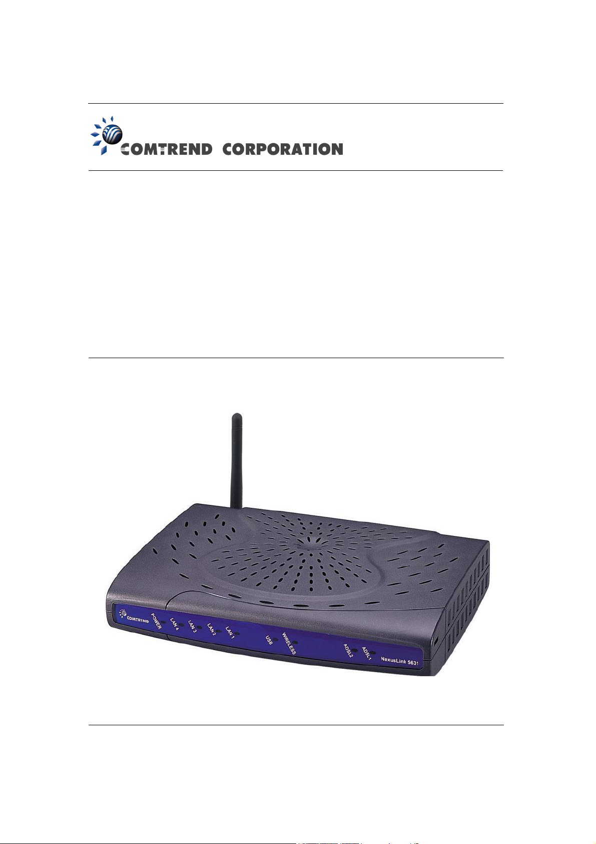
The NexusLink 5631 Wireless ADSL2+ Bonded Router features flexible networking
connectivity with dual ADSL line capability, four 10/100 Ethernet ports, two USB
ports and an 802.11g wireless LAN access point. It has robust routing capabilities
to segment and direct data streams and allows for multiple data encapsulations.
The NexusLink 5631 is a black box solution for deploying Triple Play architectures,
doubling bandwidth (48Mbps) performance over traditional ADSL2+ modems. It
provides higher level performance with embedded security, QoS, VPN and remote
management functions. As an added bonus, the USB host acts as a printer hub and
will enable future product enhancements available by software upgrade.
1.1 Features
• Dual ADSL2+ bonded
• UPnP installation
• Integrated 802.11g (WiFi) Access Point
• WPA and 802.1x
• RADIUS client
• IP /MAC address filtering
• Static route/RIP/RIP v2 routing functions
• Dynamic IP assignment
• NAT/PAT
• IGMP Proxy and fast leave
• DHCP Server/Relay/Client
• DNS Relay
• Auto PVC configuration
• Supports 16 VCs
• Embedded SNMP agent
• Web-based management
• Remote configuration and upgrade
• Supports TR-069/TR-098/TR-111 For Remote Management
• Configuration backup and restoration
• FTP server
• TFTP server
5

1.2 Application
This diagram depicts the application of the NexusLink 5631 on a wireless network.
6

1.3 Front Panel LED Indicators
The front panel LED indicators are pictured below with detailed explanation provided
in the table underneath.
LED Color Mode Function
Green On The router is powered up. POWER
Off The router is powered down.
Green On An Ethernet Link is established.
LAN 1~4
WIRELESS
ADSL 1~2
USB
Off An Ethernet Link is not established.
Green Blink Data transmitting or receiving over LAN.
Green On A USB link is established.
Off A USB link is not established.
Green Blink Data transmitting or receiving over USB.
Green On The Wireless is ready and idle.
Off The Wireless is not installed.
Green Blink
Green On
Off
Data transmitting or receiving over Wireless
The ADSL link is established.
The ADSL link is not established.
7
Chapter 2 Installation
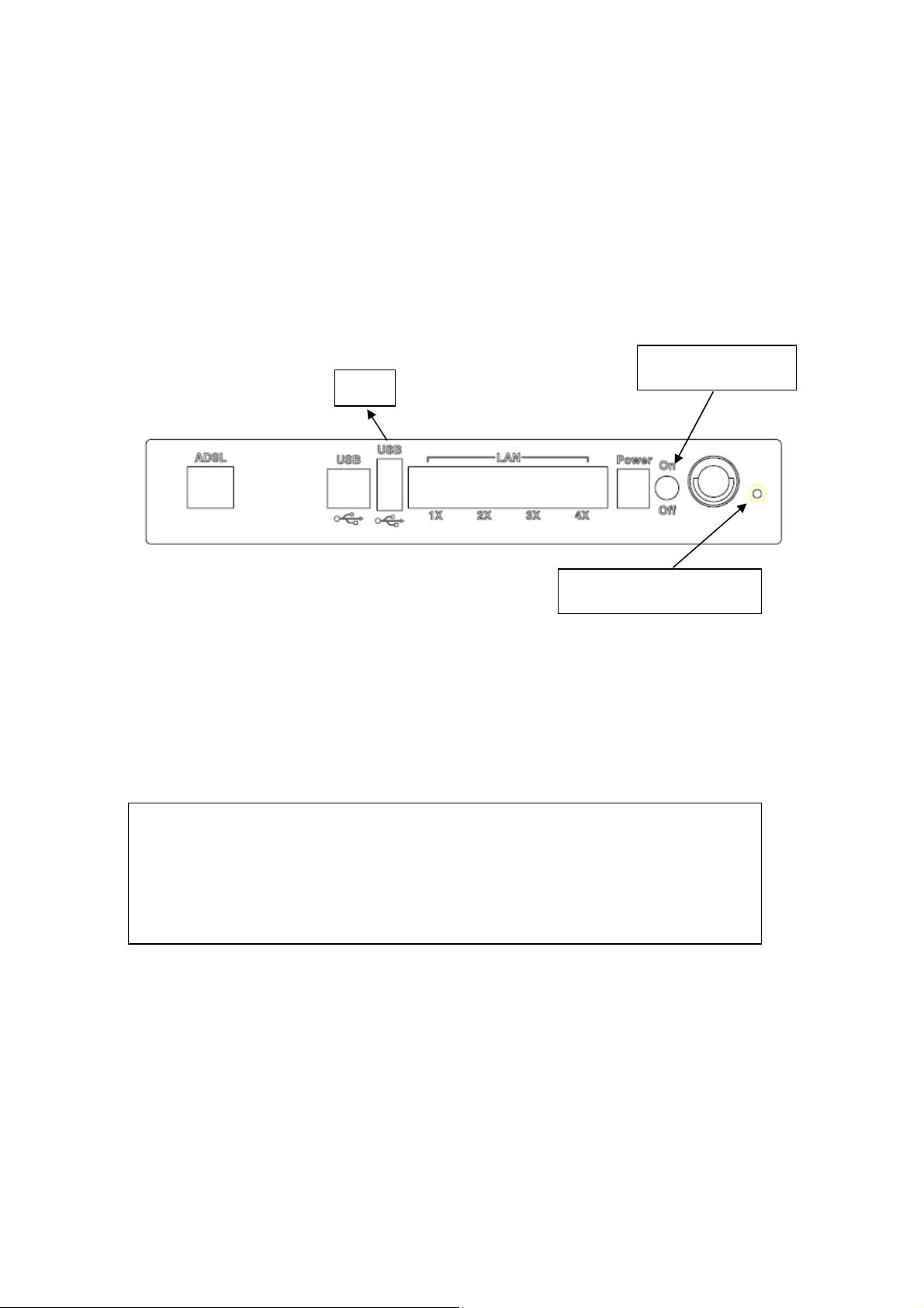
2.1 Hardware Installation
Follow the instructions below to complete the hardware installation.
A diagram of the back panel of the router is shown below for reference.
Connection to Power
Connect the power jack to the shipped power cord. Attach the power adapter to
the wall outlet or other AC source. After all connections have been made, press the
power button to turn on the device. After powering on, the router will perform a
self-test. Wait a few moments and the device will be ready to operate.
Host
Reset button
Power button
Caution 1: If the device fails to power up, or if it malfunctions, first verify that
the power supply is connected correctly. Then power it on again.
If the problem persists, contact technical support.
Caution 2: Before servicing or disassembling this equipment always disconnect
all power cords and telephone lines from the wall outlet.
Reset Button
In the rear panel, there is a reset button. To load the factory default settings, hold
the reset button down for 5 to 10 seconds.
Connection to USB port
Connect the USB port to a PC with a standard USB cable.
8

Connection to USB host port
This device is equipped with one high-speed USB 2.0 host connection. With
software support, users can connect USB devices such as printers and a hard disc to
the router. For this software release, printer service is supported.
Connection to LAN port
To connect to a hub or PC, use a RJ45 cable. You can connect the router to four LAN
devices. The ports are auto-sensing MDI/X and either straight-through cable or
crossover cable can be used.
Connection to LINE port
If you wish to connect both the router and a telephone, connect the LINE port to a
POTS splitter with a RJ14 cable.
9
2.2 USB Driver Autorun Installation
Before connecting the NexusLink 5631 to a PC with USB, the correct drivers must be
installed. The auto-run USB driver installation supports Win ME, Win 98, Win 2000,
Win XP (32 bit) and Vista (32 bit). For those using Windows XP 64 bit, the driver
must be installed manually (please see section 2.3 below for details).
Follow the procedure below to install the standard (32 bit) USB driver
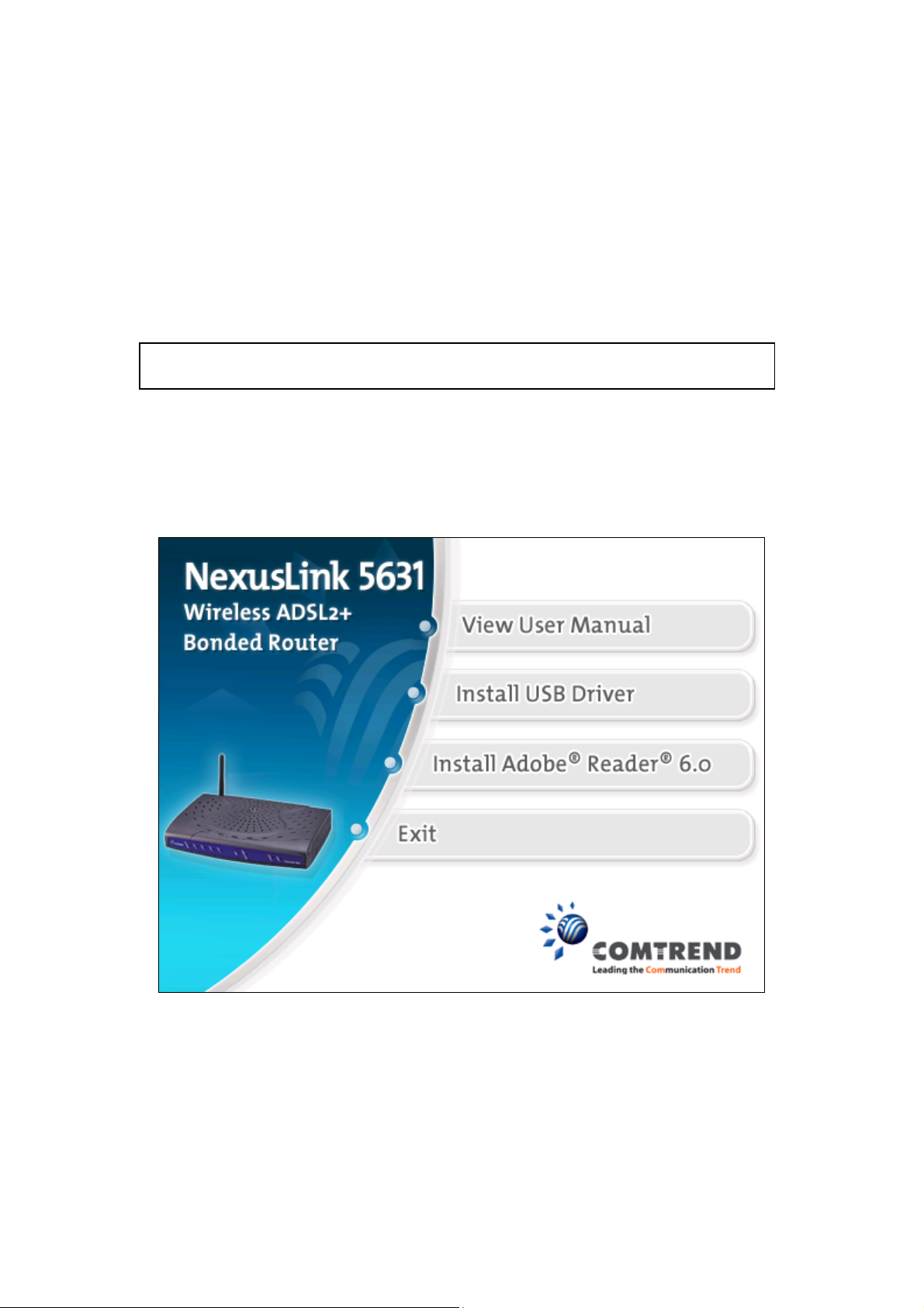
STEP 1: Insert the Installation CD and select Install USB Driver from the
autostart menu options shown below.
10
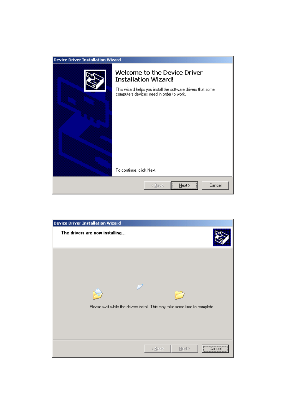
STEP 2: The following window will be displayed. Click the Next button to continue.
STEP 3: When the window displays as below, wait for the drivers to fully install.
11
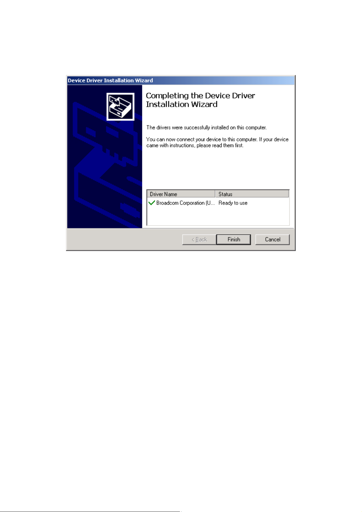
STEP 4: Click the Finish button, when the window displays as below.
STEP 5: The installation is complete. You can now connect the device to your PC
using a standard USB cable.
12
2.3 USB Driver Manual Installation (64bit OS)
Before connecting this router to a PC with USB, the correct drivers must be installed.
Follow the procedure below to manually install the 64bit USB driver
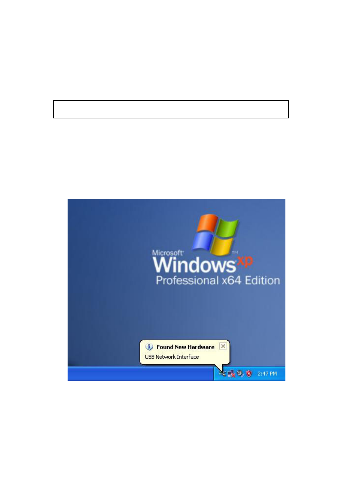
STEP 1: Connect the USB port to the PC by plugging the flat connector of a
standard USB cable into your PC and plugging the square connector into
the device. After a moment, the connection should be detected by your
PC and if so the screen will display a notice to that effect, as shown below:
13
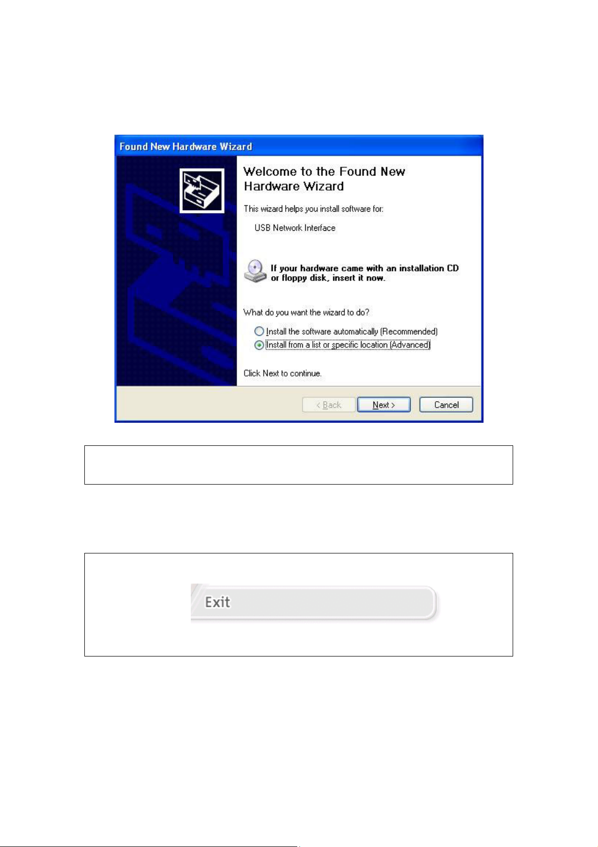
STEP 2: When the window displays as below, select Install from a list or
specific location (Advanced) and then click the Next button.
Note: This window won’t display if the USB Driver has been previously installed.
In this case, contact technical support for assistance.
STEP 3: Insert the installation CD.
Note: If you see the autostart menu (as shown in step 1 of previous section)
CLICK -
and continue with the manual installation process.
14
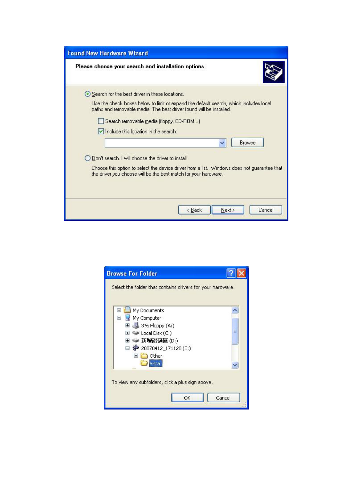
STEP 4: Select the location of the file using the Browse button, as shown above.
Normally, the file is on the CD-ROM shipped with the device.
STEP 5: Locate the Vista folder, and click OK.
15
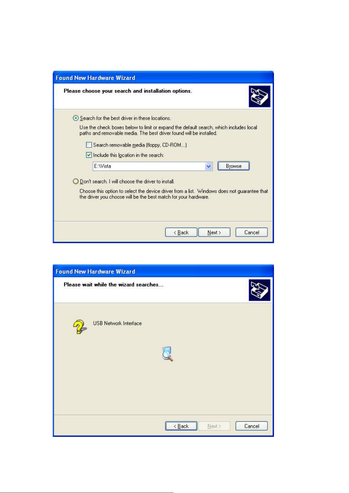
STEP 6: When the window displays as below, click the NEXT button and wait.
16

STEP 7: Click the Finish button when the window displays as below.
STEP 8: Installation is complete.
17

Chapter 3 Web User Interface
This section describes how to manage the router via a web browser. The web page
is best viewed with Microsoft Internet Explorer 5.0 and later. A unique default user
account is assigned with user name root and password 12345. The user can
change the default password later when logged in to the device.
3.1 TCP/IP Settings
The default IP address of the router (LAN port) is 192.168.1.1. To configure the
router for the first time, the configuration PC must have a static IP address within
the 192.168.1.x subnet. Follow the steps below to configure your PC IP address to
use subnet 192.168.1.x.
STEP 1: Right click on the Local Area Connection under the Network and Dial-Up
connection window and select Properties.
STEP 2: Enter the TCP/IP window and change the IP address to 192.168.1.x/24.
STEP 3: Click OK to submit settings.
18
3.2 Login Procedure
Perform the following steps to bring up the web browser and configure the router.
STEP 1: Start the Internet browser. Type the IP address for the router in the Web
address field. For example, if the IP address is 192.168.1.1, type
http://192.168.1.1
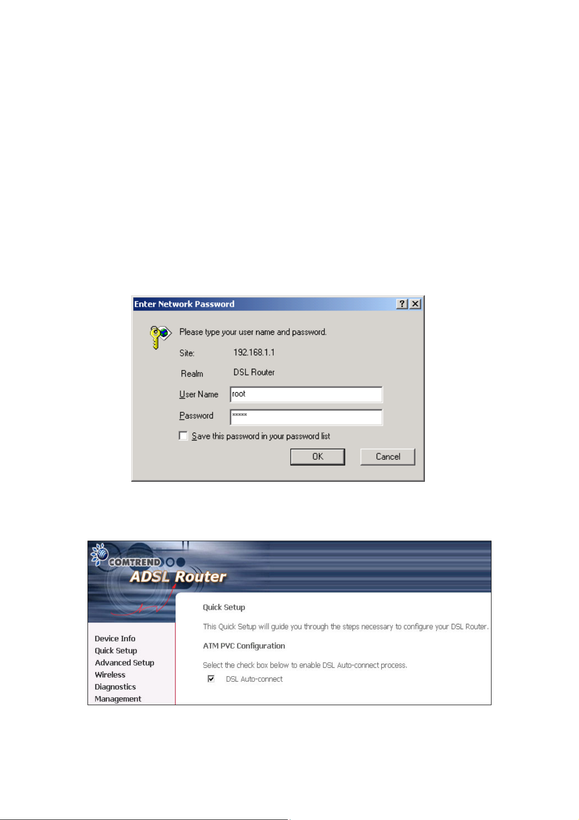
STEP 2: You will be prompted to enter your user name and password. Type root
for the user name and 12345 as the password, then click OK. These
values can be changed later (see section 9.6.3 Passwords).
STEP 3: After successfully logging in, you will reach the Quick Setup menu.
19

3.3 Default Settings
During power on initialization, the router sets all configuration attributes to default
values. It will then read the configuration profile from flash memory. The default
attributes are overwritten when identical attributes with different values are
configured. The configuration profile can be created via the web browser, telnet
user interface or other management protocols. The factory default configuration
can be restored either by resetting the device or selecting the Restore Default option
in Management Æ Settings (see section 9.1.3 Restore Default).
The following list shows the factory default settings for this router.
• LAN port IP address(es): 192.168.1.1 (ADSL1) and 192.168.1.2 (ADSL2)
• Local administrator account name: root
• Local administrator account password: 12345
• Local non-administrator account name: user
• Local non-administrator account password: user
• Remote WAN access: disabled
• Remote WAN access account name: support
• Remote WAN access account password: support
• NAT and firewall: Disabled for MER, IPoA and Bridge modes
Enabled for PPPoE and PPPoA modes
• DHCP server on LAN interface: enabled
• WAN IP address: none
• Wireless access: enabled
• SSID: Comtrend
• Wireless authentication: open (no authentication)
• Annex M enabled (all other modes disabled)
20
Chapter 4 Quick Setup
After login, the Quick Setup screen will appear as shown.
NOTE: The selections available on the main menu are based upon the configured
connection type and user account privileges.
The Quick Setup screen allows the user to configure the NexusLink 5631 for ADSL
connectivity and Internet access. It also guides the user though the WAN network
setup first and then the LAN interface setup. You can either do this manually or
follow the auto quick setup (i.e. DSL Auto-connect) instructions.
This router supports the following data encapsulation methods.
• PPP over Ethernet (PPPoE)
• PPP over ATM (PPPoA)
• MAC Encapsulated Routing (MER)
• IP over ATM (IPoA)
• Bridging
21

The following configuration considerations apply:
• The WAN network operating mode operation depends on the service provider’s
configuration in the Central Office and Broadband Access Server for the PVC
• If the service provider provides PPPoE service, then the connection selection
depends on whether the LAN-side device (typically a PC) is running a PPPoE
client or whether the router is to run the PPPoE client. The router can support
both cases simultaneously.
• If some or none of the LAN-side devices do not run PPPoE client, then select
PPPoE. If every LAN-side device is running a PPPoE client, then select Bridge In
PPPoE mode, the device also supports pass-through PPPoE sessions from the
LAN side while simultaneously running a PPPoE client from non-PPPoE LAN
devices. In most cases, NAT and firewall should always be enabled when PPPoE
or PPPoA mode are selected, but they can be enabled or disabled by the user
when MER or IPoA is selected, NAT and firewall are always disabled when Bridge
mode is selected.
• Depending on the network operating mode, and whether NAPT and firewall are
enabled or disabled, the main panel will display or hide the NAPT/Firewall menu.
For instance, at initial setup, the default network operating mode is Bridge. The
main panel will not show the NAPT and Firewall menu.
NOTE: Up to sixteen PVC profiles can be configured and saved on the flash
memory. To activate a particular PVC profile, you need to navigate all the
Quick Setup pages until the last summary page, then click on the Finish
button and reboot the system.
22

4.1 Auto Quick Setup
The auto quick setup requires the ADSL link to be up. The ADSL router will
automatically detect the PVC, so just follow the easy online instructions.
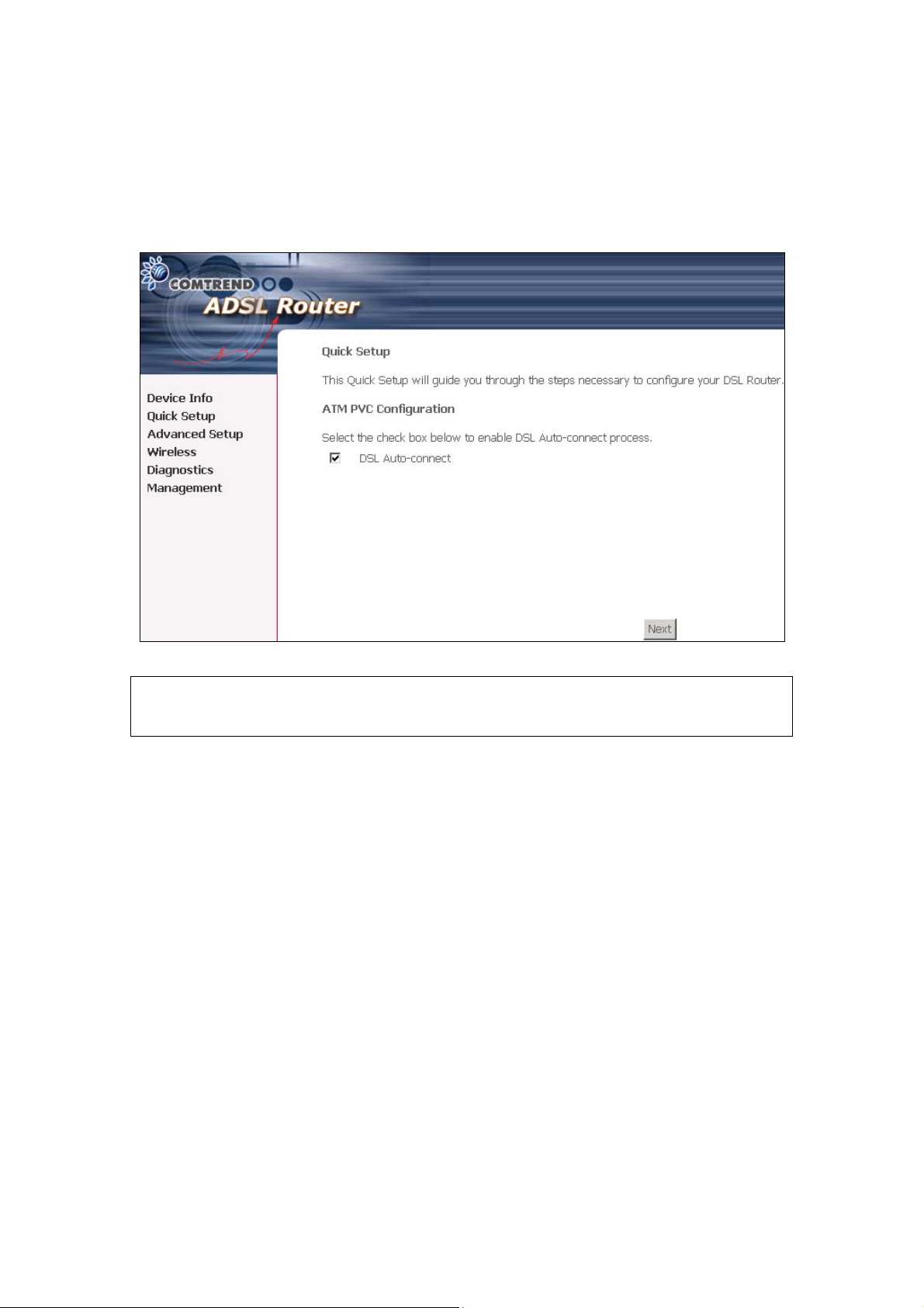
STEP 1: Select Quick Setup to display this screen.
STEP 2: Click Next to start the setup process. Follow the online instructions to
complete the settings. This procedure will skip some processes such as
the PVC index and encapsulation mode selection.
STEP 3: After the settings are complete, you can use the ADSL service.
23
4.2 Manual Quick Setup
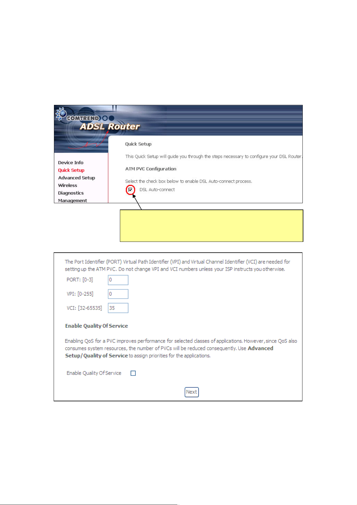
STEP 1: Click Quick Setup and un-tick the DSL Auto-connect checkbox to
enable manual configuration of the connection type.
Untick this checkbox to enable manual setup and display
the following screen.
STEP 2: Enter the PORT, Virtual Path Identifier (VPI) and Virtual Channel Identifier
(VCI) values. Select Enable Quality Of Service if required and click Next.
24
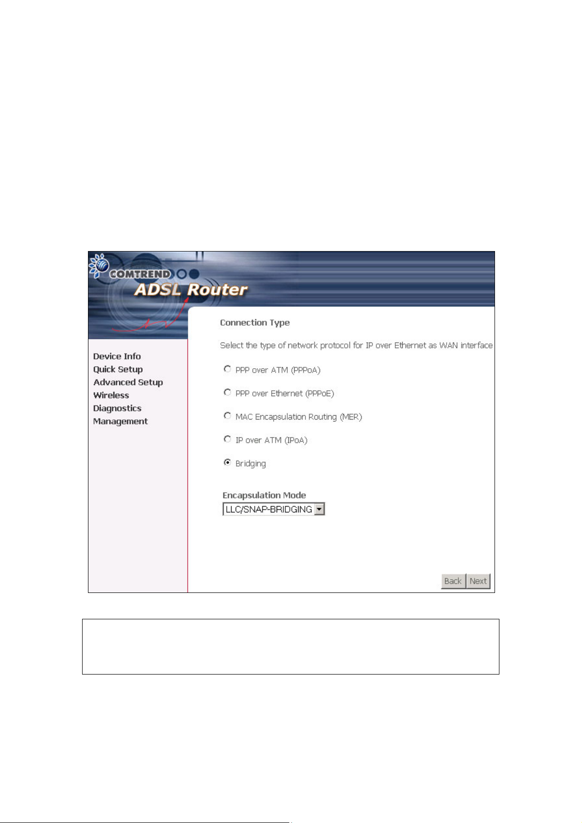
STEP 3: Choose an Encapsulation mode.
Choosing different connection types provides different encapsulation modes.
• PPPoA- VC/MUX, LLC/ENCAPSULATION
• PPPoE- LLC/SNAP BRIDGING, VC/MUX
• MER- LLC/SNAP-BRIDGING, VC/MUX
• IPoA- LLC/SNAP-ROUTING, VC MUX
• Bridging- LLC/SNAP-BRIDGING, VC/MUX
NOTE: Subsections 4.2.1 - 4.2.4 describe the PVC setup procedure further.
Choosing different connection types pops up different settings requests.
Enter appropriate settings that are required by your service provider.
25
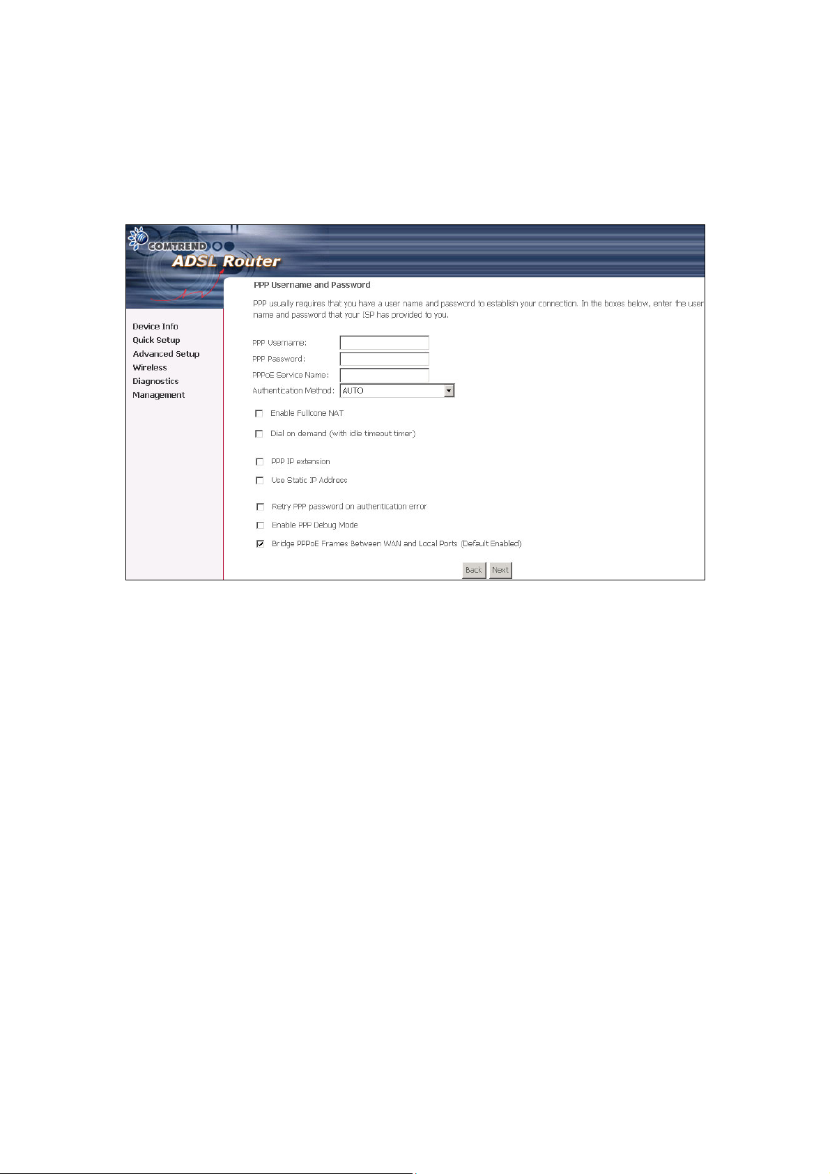
4.2.1 PPP over ATM (PPPoA) and PPP over Ethernet (PPPoE)
STEP 4: Select the PPP over ATM (PPPoA) or PPP over Ethernet (PPPoE) radio
button and click Next. The following screen appears.
Enable Fullcone NAT
Known as one-to-one NAT, all requests from the same internal IP address and
port are mapped to the same external IP address and port. An external host can
send a packet to the internal host, by sending a packet to the mapped external
address.
PPP Username/PPP Password
The PPP Username and the PPP password requirement are dependent on the
particular requirements of the ISP or the ADSL service provider. The WEB user
interface allows a maximum of 256 characters in the PPP user name and a maximum
of 32 characters in PPP password.
26

Disconnect if no activity
The router can be configured to disconnect if there is no activity for a period of time
by selecting the Dial on demand check box. When the checkbox is ticked, you need
to enter the inactivity timeout period. The timeout period ranges from 1 minute to
4320 minutes.
PPP IP Extension
The PPP IP Extension is a special feature deployed by some service providers.
Unless your service provider specially requires this setup, do not select it.
The PPP IP Extension supports the following conditions:
• Allows only one PC on the LAN
• The public IP address assigned by the remote side using the PPP/IPCP protocol
is actually not used on the WAN PPP interface. Instead, it is forwarded to the PC
LAN interface through DHCP. Only one PC on the LAN can be connected to the
remote, since the DHCP server within the ADSL router has a single IP address to
assign to a LAN device.
• NAPT and firewall are disabled when this option is selected.
• The ADSL router becomes the default gateway and DNS server to the PC through
DHCP using the LAN interface IP address.
• The ADSL router extends the IP subnet at the remote service provider to the LAN
PC. That is, the PC becomes a host belonging to the same IP subnet.
• The ADSL router bridges the IP packets between WAN and LAN ports, unless the
packet is addressed to the router’s LAN IP address.
Use Static IP Address
Unless your service provider specially requires this setup, do not select it.
If selected, enter your static IP address.
Retry PPP password on authentication error
Tick the box to select.
Enable PPP Debug Mode
Enable the PPPoE debug mode. The system will put more PPP connection
information in System Log. This is used for debugging purposes.
Bridge PPPoE Frames Between WAN and Local Ports (Default Enabled)
If Enabled, the function can create a local PPPoE connection to the WAN side.
27
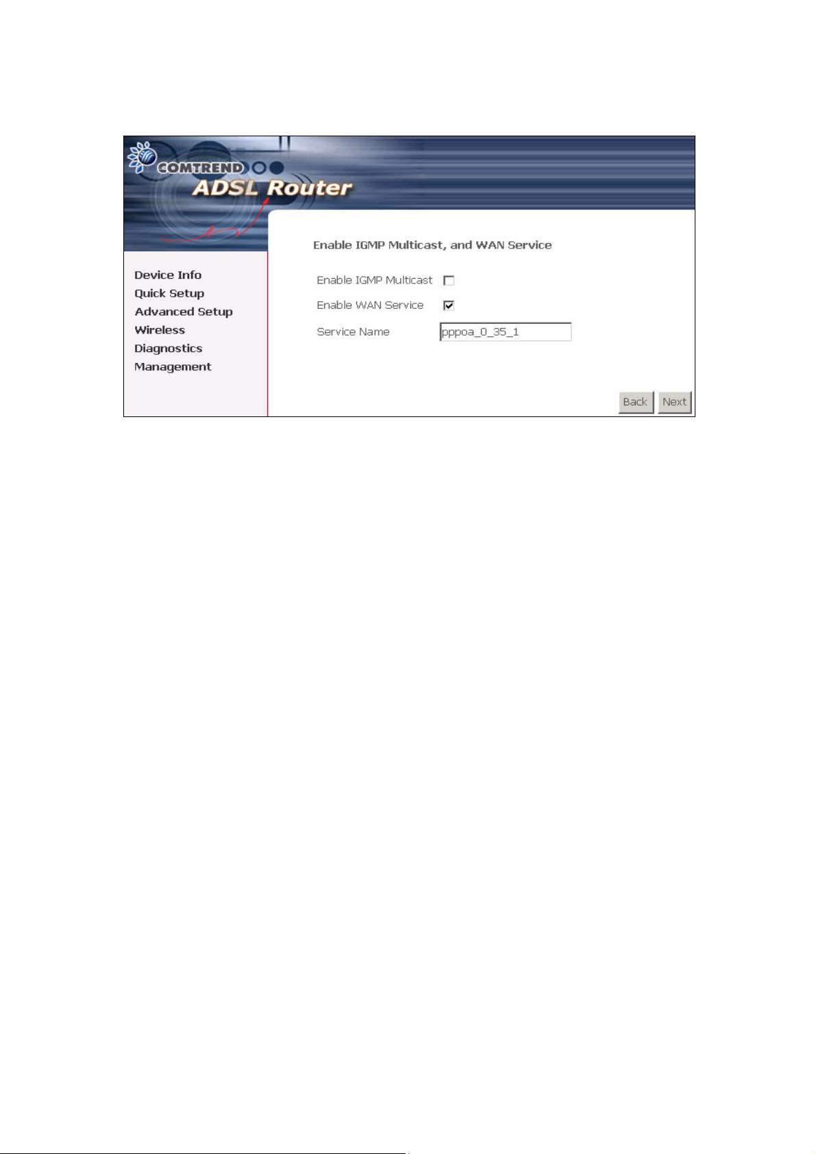
STEP 5: Click Next to display the following screen.
Enable IGMP Multicast checkbox:
Tick the checkbox to enable IGMP multicast (proxy). IGMP (Internet Group
Membership Protocol) is a protocol used by IP hosts to report their multicast group
memberships to any immediately neighboring multicast routers.
Enable WAN Service checkbox:
Tick this item to enable the ATM service. Untick it to stop the ATM service.
Service Name:
This is user-defined.
28
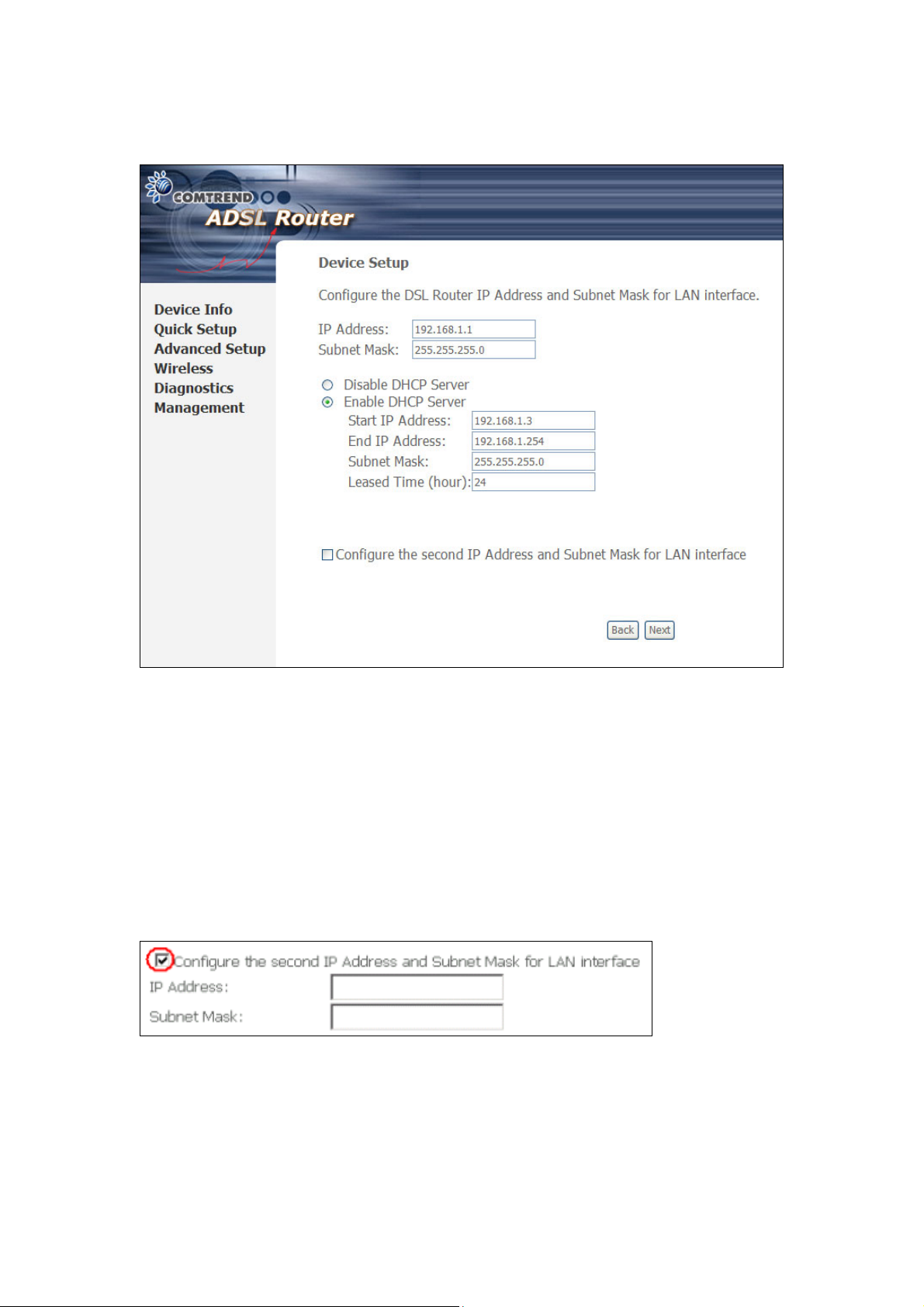
STEP 6: After entering your settings, select Next. The following screen appears.
This screen allows the user to configure the LAN interface IP address, subnet mask
and DHCP server. To assign dynamic IP address, DNS server and default gateway
to other LAN devices, select the button Enable DHCP server on the LAN and enter
the start and end IP addresses and DHCP leased time.
Since the router occupies the first two IP addresses (192.168.1.1 and 192.168.1.2),
the default private address range provided by the ISP server in the router is
192.168.1.3 through 192.168.1.254.
To configure a secondary IP address for the LAN port, click the checkbox, as shown.
29
 Loading...