

Page 1
NexusLink 3112u
Multi-DSL Bonded Router
User Manual
Version A1.1, June 04, 2014
261103-009
Page 2

1
Preface
This manual provides information related to the installation and operation of this
devic e . The individual r eading this manual is presumed to have a basic
understanding of telecommunications terminology and concepts.
If you find the product to be inoperable or malfunctioning, please conta ct technical
support for immediate service by email at [email protected]
For product update, new product release, manual revision, or software upgrades,
please visit our website at http://www.comtrend.com
Important Safety Instructions
With reference to u np acking, installation, use, and maintenance of your electronic
device, the following basic guidelines are recommended:
• Do not use or install this product near water, to avoid fire or shock hazard. For
example, near a bathtub, kitchen sink o r laundr y tub, or near a s wimming poo l.
Also, do not expose the equipment to rain or damp ar eas (e.g. a wet basement).
• Do not connect the power supply cord on elevated surfaces. Allow it to lie freely .
There should be no obstructions in its path and no hea vy items should be placed
on the cord. In addition, do not walk on, step on, or mistreat the cor d.
• Use only the power cord and adapter that are shipped with this device.
• T o safeguard the equipment against overheating, make sure that all openings in
the unit that offer exposure to air are not blocked.
• Avoid using a telephone (other than a cordless type) during an electr ical storm.
There may be a remote risk of electric shock from lightening. Also, do not use
the telephone to report a gas leak in the vicinity of the leak.
• Never install telephone wiring during stormy weather conditions.
CAUTION:
To reduce the risk of fire, use only No. 26 AWG or larger
telecommunication line cord.
Always disconnect all telephone lines from the wall outlet before servicing
or disassembling this equipment.
WARNING
Disconnect the power line from the device before servicing.
Power supply specifications are clearly stated in Appendix C –
Specifications.
Page 3
2
Copyright
Copyright©2014 Comtrend Corporation. All rights reserved. The information
contained herein is proprietar y to Comtrend Corporation. No part of this document
may be translated, tr anscr ibed, reprod uced, in any fo rm, or by any means without
prior written consent of Comtrend Corporation.
This program is free software: you can redistribute it and/or modify it unde r the
terms of the GNU General Public License as published by the Free Software
Foundation, either version 3 of the License, or (at your option) any later version.
This program is distributed in the ho p e that it will be useful, but WITHOUT ANY
WARRANTY; without even the implied warranty of MERCHANTABILITY or FITNESS
FOR A PARTIC ULAR PURPOSE. See the GNU General Public License for more
details.
Y ou should have re ceived a copy of the GNU General Public License
along with this program. If not, see http://www.gnu.org/licenses/
NOTE: This document is subject to change without notice.
Protect Our Environment
This symbol indicates that when the equipment has reached the end of
its useful life, it must be taken to a recycling centre and processed
separate from domestic waste.
The cardboard box, the plastic co ntained in the packaging, and the par ts that make
up this router can be recycled in accordance with regionally established regulations.
Never dispose of this electronic equipment along with your household waste; you
may be subject to penalties or sanctions under the law. Instead, please be
responsible and ask for disposal instructions from your local government.
Page 4

3
Table of Contents
CHAPTER 1 INTRODUCTION ........................................................................................................... 6
1.1 FEATURES ........................................................................................................................................ 7
CHAPTER 2 INSTALLATION ............................................................................................................. 8
2.1 HARDWARE SETUP ........................................................................................................................... 8
2.2 HARDWARE SETUP ........................................................................................................................... 8
2.3 LED INDICATORS........................................................................................................................... 10
CHAPTER 3 WEB USER INTERFACE ............................................................................................ 12
3.1 DEFAULT SETTINGS ....................................................................................................................... 12
3.2 IP CONFIGURATION ........................................................................................................................ 13
3.3 LOGIN PROCEDURE ........................................................................................................................ 15
CHAPTER 4 DEVICE INFORMATION ........................................................................................... 17
4.1 WAN ............................................................................................................................................. 19
4.2 STATISTICS ..................................................................................................................................... 20
4.2.1 LAN Statistics.................................................................................................................. 20
4.2.2 WAN Service ................................................................................................................... 21
4.2.3 XTM Statistics ................................................................................................................. 22
4.2.4 xDSL Statistics ................................................................................................................ 23
4.3 ROUTE ........................................................................................................................................... 28
4.4 ARP ............................................................................................................................................... 29
4.5 DHCP............................................................................................................................................ 29
4.6 NAT SESSION ................................................................................................................................ 31
4.7 IGMP PROXY ................................................................................................................................ 32
4.8 IPV6 .............................................................................................................................................. 33
4.8.1 IPv6 Info ................................................................................................................................ 33
4.8.2 IPv6 Neighbor ....................................................................................................................... 34
4.8.3 IPv6 Route ............................................................................................................................. 35
4.9 NETWORK MAP ............................................................................................................................. 36
4.10 WIRELESS .................................................................................................................................... 37
4.10.1 Station Info .......................................................................................................................... 37
4.10.2 Site Survey ........................................................................................................................... 38
CHAPTER 5 BASIC SETUP............................................................................................................... 39
5.1 WAN SETUP ................................................................................................................................... 40
5.1.1 WAN Service Setup ................................................................................................................ 41
5.2 NAT .............................................................................................................................................. 42
5.2.1 Virtual Servers ................................................................................................................ 42
5.2.2 Port Triggeri ng ............................................................................................................... 44
5.2.3 DMZ Host ....................................................................................................................... 46
5.2.4 IP Addr es s Map .............................................................................................................. 47
5.2.5 IPSEC ALG ..................................................................................................................... 49
5.2.6 SIP ALG .......................................................................................................................... 50
5.3 LAN .............................................................................................................................................. 51
5.3.1 LAN IPv6 Autoconfig ............................................................................................................. 54
5.3.2 Static IP Neighbor ................................................................................................................. 57
5.3.3 UPnP ..................................................................................................................................... 58
5.4 WIRELESS ...................................................................................................................................... 59
5.4.1 Basic ...................................................................................................................................... 59
5.4.2 Security .................................................................................................................................. 61
5.5 PARENTAL CONTROL...................................................................................................................... 64
5.5.1 Time Restriction .............................................................................................................. 64
5.5.2 URL Filter....................................................................................................................... 65
5.6 HOME NETWORKING ...................................................................................................................... 67
5.6.1 Print Server ........................................................................................................................... 67
5.6.2 DLNA ..................................................................................................................................... 67
5.6.3 Storage Se r vi ce ...................................................................................................................... 68
Page 5

4
CHAPTER 6 ADVANCED SETUP ..................................................................................................... 69
6.1 AUTO-DETECTION SETUP ............................................................................................................... 69
6.2 SECURITY ...................................................................................................................................... 74
6.2.1 IP Filtering ..................................................................................................................... 74
6.2.2 MAC Filtering................................................................................................................. 77
6.3 QUALITY OF SERVICE (QOS) .......................................................................................................... 79
6.3.1 QoS Queue Setup ............................................................................................................ 80
6.3.2 QoS Policer .................................................................................................................... 82
6.3.3 QoS Classification .......................................................................................................... 84
6.4 ROUTING ....................................................................................................................................... 86
6.4.1 Default Ga te wa y ............................................................................................................. 86
6.4.2 Static Route ..................................................................................................................... 87
6.4.3 Policy Ro uting ................................................................................................................ 88
6.4.4 RIP .................................................................................................................................. 89
6.5 DNS .............................................................................................................................................. 90
6.5.1 DNS Server ..................................................................................................................... 90
6.5.2 Dynamic DNS ................................................................................................................. 91
6.5.3 DNS Entries .................................................................................................................... 92
6.5.4 DNS Proxy/Relay ............................................................................................................ 93
6.6 DSL ............................................................................................................................................... 94
6.7 DSL BONDING ............................................................................................................................... 96
6.8 INTERFACE GROUPING ................................................................................................................... 97
6.9 IP TUNNEL ................................................................................................................................... 100
6.9.1 IPv6inIPv4 ........................................................................................................................... 100
6.9.2 IPv4inIPv6 ........................................................................................................................... 101
6.10 CERTIFICATE .............................................................................................................................. 102
6.10.1 Local ............................................................................................................................. 102
6.10.2 Trusted CA .................................................................................................................... 104
6.11 POWER MANAGEMENT .............................................................................................................. 105
6.12 MULTICAS T................................................................................................................................ 106
6.13 WIRELESS .................................................................................................................................. 108
6.13.1 Basic .................................................................................................................................. 108
6.13.2 Security .............................................................................................................................. 110
6.13.3 WPS ................................................................................................................................... 113
6.13.4 MAC Filter......................................................................................................................... 114
6.13.5 Wireless Brid ge .................................................................................................................. 116
6.13.6 Advanced ........................................................................................................................... 117
CHAPTER 7 DIAGNOSTICS ........................................................................................................... 120
7.1 DIAGNOSTICS – INDIVIDUAL TESTS ............................................................................................. 120
7.2 FAULT MANAGEMENT .................................................................................................................. 121
7.3 UPTIME STATUS ........................................................................................................................... 122
7.4 PING ............................................................................................................................................ 122
7.5 TRACE ROUTE ............................................................................................................................. 123
7.6 SYSTEM UTILIZATION .................................................................................................................. 124
CHAPTER 8 MANAGEMENT ........................................................................................................ 125
8.1 SETTINGS ..................................................................................................................................... 125
8.1.1 Backup Settings............................................................................................................. 125
8.1.2 Update Settings ............................................................................................................. 126
8.1.3 Restore Default ............................................................................................................. 126
8.2 SYSTEM LOG ............................................................................................................................... 127
8.3 SNMP AGENT ............................................................................................................................. 129
8.4 TR-069 CLIENT ........................................................................................................................... 130
8.5 INTERNET TIME ........................................................................................................................... 132
8.6 ACCESS CONTROL ....................................................................................................................... 133
8.6.1 Passwords ......................................................................................................................... 133
8.6.2 Service Access ................................................................................................................... 135
8.6.3 IP Address ......................................................................................................................... 136
8.7 UPDATE SOFTWAR E ..................................................................................................................... 137
8.8 REBOOT ....................................................................................................................................... 138
Page 6

5
CHAPTER 9 LOGO UT ..................................................................................................................... 139
APPENDIX A - FIREWALL ............................................................................................................. 140
APPENDIX B - PIN ASSIGNMENTS .............................................................................................. 143
APPENDIX C – SPECIFICATIONS ................................................................................................ 144
APPENDIX D - SSH CLIENT .......................................................................................................... 146
APPENDIX E - CONNECTION SETUP ......................................................................................... 147
APPENDIX F - WPS OPERATION ................................................................................................. 179
APPENDIX G - PRINTER SERVER ............................................................................................... 184
Page 7

6
Chapter 1 Introduction
The NexusLink 3112u Multi DSL Bonde d Route r is a s ingle bo x solutio n for t riple p lay
applications. It features dual xDSL bonded ports that provide twice the xDSL
bandwidth (ADSL2+ in both ATM/PTM modes and VDSL2 PTM
8a/8b/8c/8d/12a/12b/17a profiles ) over comparable single-port mode ls. With PTM
mode supported, it can provide better performance than a regular A TM mode router .
The NexusLink 3112u is equipped with three Fast Ethernet ports, one Gigabit port
and 802.11n WLAN Access Point (AP). It goes above and beyond with high level
features such as QoS, VPN and remote management (with TR-069 support).
Page 8

7
• Integrated 802.11n AP
• Configuration backup and
• Automatically switches to
• Up to 16 PVCs and Up to 8 PTM
• Supports bonded xDSL lines
• IPv6 compliant
• VDSL2 12a/12b profile support
• Printer Server (IPP)
• Per-VC packet level QoS
• Firmware upgrade and
• WPA and 802.1x
• Auto PVC configuration
• WPS 2.0
• UPnP
• RADIUS client
• IP/MAC address filtering
• Up to VDSL2 17a Profile
• Dynamic IP assignment
• US0
• Parental Control
•PhyR and G.INP
• DHCP Server/Client
• G.Vector
• DNS Relay/Proxy
• Static routing & RIP/RIP v2
• FTP/TFTP server
• NAT/PAT
• USB mass-storage and file sharing
• IGMP Snooping/Proxy and fa st leave
• Embedded SNMPv2 agent
• Supports remote administration
• HTTPS /HTTP server
• Web-based management
• TR-069/TR-098/TR-111
1.1 Features
(802.11b/g backward-compatible)
ADSL2+/VDSL2 according to the
restoration
flows
port setting of DSLAM
configuration
(Samba)
Page 9

8
Chapter 2 Installation
Reset Button
Power Port
Ethernet (LAN) Ports
DSL Port
Power Button
2.1 Hardware Setup
Follow the instructions below to complete the hardware setup.
Non-stackable
This device is not stackable – do not place units on top of each other, otherwise
damage could occur.
2.2 Hardware Setup
Follow the inst ructions below to complete the hardware setup.
BACK PANEL
The figure below shows the back panel of the device.
Power ON
Press the power button to the OFF position (OUT). Connect the power adapter to the
power port. Attach the power adapter to a wall outlet or other AC sourc e. Press t he
power button to the ON position (IN). If the Power LED displays as expected then
the device is ready for setup (see section 2.3 LED Indicators for details).
Caution 1: If the device fails to power up, or it malfunctions, first verify that the
power cords are connected securely and then power it on again. If the
problem persists, contact technical suppo rt.
Caution 2: Before servicing or disassembling this equipment, disconnect all power
cords and telephone lines from their outlets.
Reset Button
Restore the default parameters of the device by pressing the Reset button for 10
seconds. After the device has rebooted successfully, the front panel should display
as expected (see section 2.3 LED Indicators for details).
Page 10
9
NOTE: If pressed down for more than 60 seconds, the NexusLink 3112u will go
into a firmware update state (CFE boot mode). The firmware can then
be updated using an Internet browser pointed to the default IP address.
GB ETH Port
Use RJ45 straight through or cro ssover MDI/X cable to connect to Ethernet WAN.
Ethernet (LAN) Ports
Use 10/100 BASE-T RJ-45 cables to connect up to four network dev ices (as the GB
ETH port can also be used). These ports are auto-sensing MDI/X; so eit h er
straight-through or crossover cable can be used.
USB Host Port (Type A)
This port can be used to connect the router to the print server.
DSL Port
Connect to a VDSL with this RJ14 Po rt. This device contains a micro filter which
removes the ana log phone signal. If you wish, you can co nnect a regular telephone
to the same line by using a POTS splitter.
FRONT PANEL
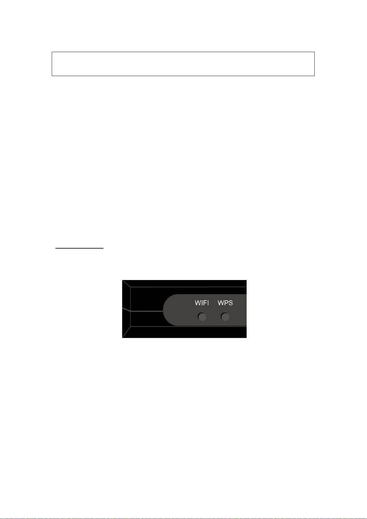
The Wi-Fi & WPS buttons are located on the bottom-left of the front panel, as sho wn.
WiFi Switch
Press this button to enable/disable the wireless LAN (WLAN).
WPS Button
Press this button to begin searching for WPS clients. These clients must also enable
WPS push button mode (see Appendix F - WPS OPERATION for instructions).
Page 11
10
2.3 LED Indicators
LED
Color
Mode
Function
Off
The device is powered down.
POST (Power O n Self Test) failure or o ther
or passing customer data.
Green
On
Powered device connected to the
associated port.
Off
No activity, modem powered off, no cable
Blink
Traffic is passing.
Powered device connected to the
associated port.
No activity, modem powered off, no cable
associated port.
Blink
Traffic is passing.
On
An Ethernet Link is established.
An Ethernet Link is not established.
Blink
Data transmitting or receiving over
Ethernet.
On
WPS enabled.
Off
WPS disenabled.
Blink
The router is searching for WPS clients.
On
The wireless module is ready.
(i.e. installed and enabled).
The wireless module is not ready.
(i.e. either not installed or disabled).
Blink
Data transmitting or receiving ov er WLAN.
On
The DSL1 link is established.
Off
The device is powered down.
Blink
DSL1 attempting sync:
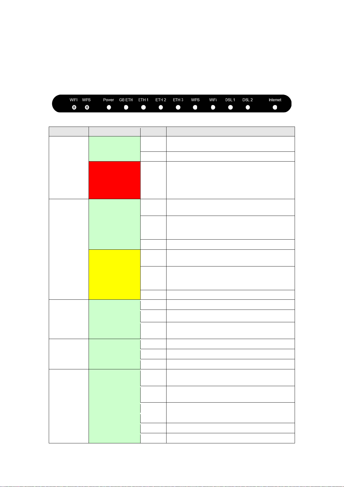
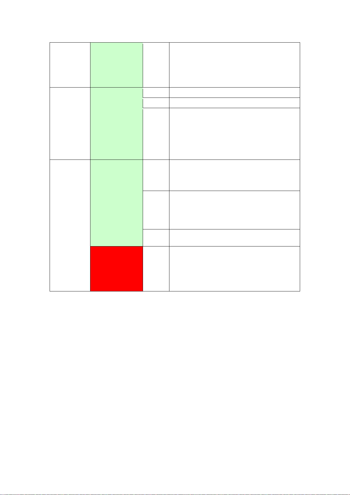
The front panel LED indicators are shown belo w and explained in the fo llowing table.
This information can be used to c heck t he status of the device a nd its co nnec tions.
POWER
GB ETH
Green
Red
(for 1000
Base-T)
Yellow
(for 10/100
Base-T)
On The device is powered up.
On
On
Off
malfunction. A malfunction is any error of
internal sequence or state that will prevent
the device from connecting to the DSLAM
or no powered device connected to the
associated port.
or no powered device connected to the
ETH 1-3
WPS Green
WiFi Green
DSL1
Green
Green
Off
Off
Page 12
11
Flashing at 2 Hz with a 50% duty cycle
On
The DSL2 link is established.
Off
The device is powered down.
Blink
DSL2 attempting sync:
On
IP connected and no traffic detect ed. If
if an VDSL connection is still present.
Off
Modem power off, modem in bridged mode
timeout, the light is turned off.
Blink
IP connected and IP Traffic is passing thru
the device (either direction)
when trying to detect c arr ie r s ignal flashing at 4
Hz with a 50% duty cycle when the carrier has
been detected and the modem is trying to train.
DSL2 Green
Green
INTERNET
Red
Flashing at 2 Hz with a 50% duty cycle
when trying to detect c arr ie r s ignal flashing at 4
Hz with a 50% duty cycle when the carrier has
been detected and the modem is trying to train.
an IP or PPPoE session is dropped due to
an idle timeout, the light will remain green
or VDSL connection not present. In
addition, if an IP or PPPo E session is
dropped for any reason, other than an idle
Device attempted to become IP connected
and failed (no DHCP response, no PPP oE
On
response, PPPoE authentication failed, no
IP address from IPCP, etc.)
Page 13

12
Chapter 3 Web User Interface
This section describes how to access the device via the web user interface (WUI)
using an Internet browser such as Internet Explorer (version 5.0 and later).
3.1 Default Settings
The factory default settings of this device are summarized below.
• LAN IP address: 192.168.1.1
• LAN subnet mask: 255.255.255.0
• Administrative access (username: root, password: 12345)
• User access (username: user, password: user)
• Remote (WAN) access (username: support, password: support)
• WLAN access: enabled
Technical Note
During pow er on, the devi ce initializes a ll settings t o default values. It wi ll then
read the configuration profile from the permanent storage section of flash memory .
The default attributes are overwritten whe n identical attributes with different values
are configured. The configuration profile in permanent storage can be created via
the web use r interface or t elnet user interfa ce, or other manag ement protocols .
The factory default configuration can be restored either by pushing the reset button
for more than ten seconds until the power indicate s LED blinking o r b y c licking the
Restore Default Configuration option in the Restore Settings screen.
Page 14
13
3.2 IP Configuration
DHCP MODE
When the NexusLink 3112u powers up, the onboard DHCP server will switch on.
Basically, the DHCP server issues and reserves IP addresses for LAN devices, such
as your PC.
To obtain an IP address from the DCHP server, follow the steps provided below.
NOTE: The following procedure assumes you are running Windows XP.
However, the general steps involved are similar for most operating
systems (OS). Check your OS support doc umentation for fur ther details.
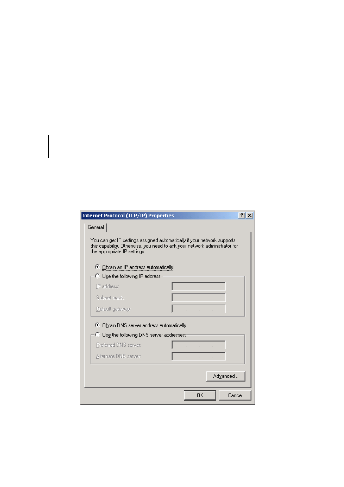
STEP 1: From the Network Conne ctions window , open Local Area Conne ction (You
may also acce ss this scre en by double-clicking the Local Area Connection
icon on your taskbar). Click the Properties button.
STEP 2: Select Internet Protocol (TCP/IP) and click the Properties button.
STEP 3: Select Obtain an IP address automatically as shown below.
STEP 4: Click OK to submit these settings.
If you experience difficulty with DHC P mode, you can try static IP mode instead.
Page 15
14
STATIC IP MODE
In static IP mode, you assign IP settings to your PC manually.
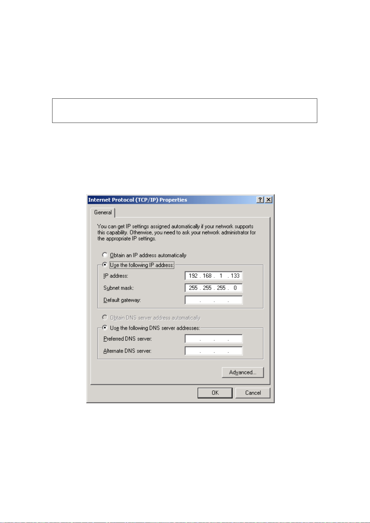
Follow these steps to configure your PC IP address to use subnet 192.168.1.x.
NOTE: The following procedure assumes you are running Windows XP.
However, the general steps involved are similar for most operating
systems (OS). Check your OS support doc umentation for fur ther details.
STEP 1: From the Network Connections window, open Local Area Connection (You
may also acce ss this scre en by double-clicking the Local Area Connection
icon on your taskbar). Click the Properties button.
STEP 2: Select Internet Protocol (TCP/IP) and click the Properties button.
STEP 3: Change the IP address to the 192.168.1.x (1<x<255) subnet with subnet
mask of 255.255.255.0. The screen should now display as shown below.
STEP 4: Click OK to submit these settings.
Page 16
15
3.3 Login Procedure
Perform the following steps to login to the web user interface.
NOTE: The default settings can be found in section 3.1 Default Settings
STEP 1: Start the Internet browser and enter the default IP address for the device
in the Web address field. For example, if the default IP address is
192.168.1.1, type http://192.168.1.1.
NOTE: For local administration (i.e. LAN access), the PC running the bro w ser
must be attached to the Ethernet, and not necessarily to the device.
For remote access (i.e. WAN), use the IP address shown on the Device
Information screen and login with remote username and password.
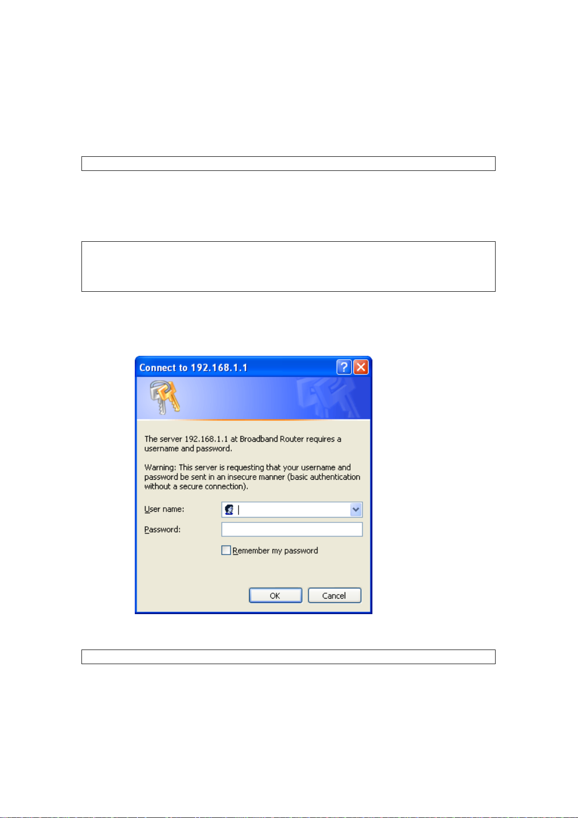
STEP 2: A dialog box will appear, such as the one below. Enter the default
username and password, as defined in section 3.1 Default Settings.
.
Click OK to continue.
NOTE: The login pa ssword can be changed later (see section 8.6.1 Passwords
).
Page 17
16
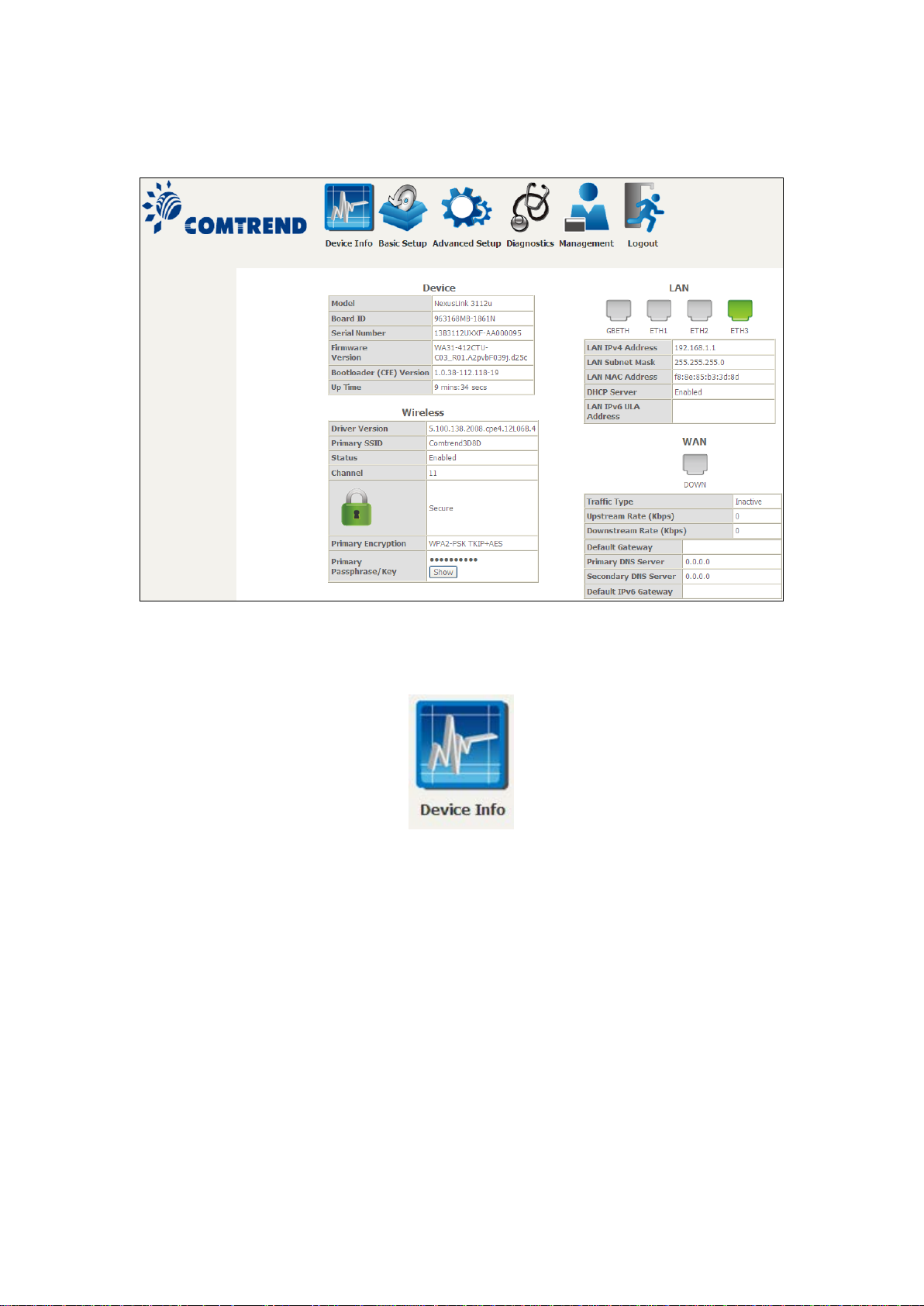
STEP 3: After successfully logging in for the first time, you will reach this screen.
You can also reach this page by clicking on the following icon located at the top of
the screen.
Page 18
17
Chapter 4 Device Information
You can reach this page by clicking on the following icon located at the top of the
screen.
The web user interface window is divided into tw o frames, the main menu (at left)
and the display screen (on the right). The main menu has several options and
selecting each of these options opens a submenu with more selections.
NOTE: The menu items shown are b ased upon the configured conne ction(s) and
user account privileges. For example, if NAT and Firewall are enabled, the
main menu will display the NAT and Security submenus. If either is
disabled, their corresponding menu(s) will a lso be disabled.
Device Info is the first selection on the main menu so it will be discussed first.
Subsequent chapte rs will introduce the other main menu options in sequence.
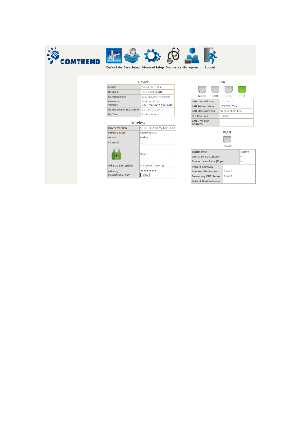
The Device Info Summary screen displays at startup.
Page 19
18
This screen shows hardware, software, IP settings and other related information.
Page 20
19
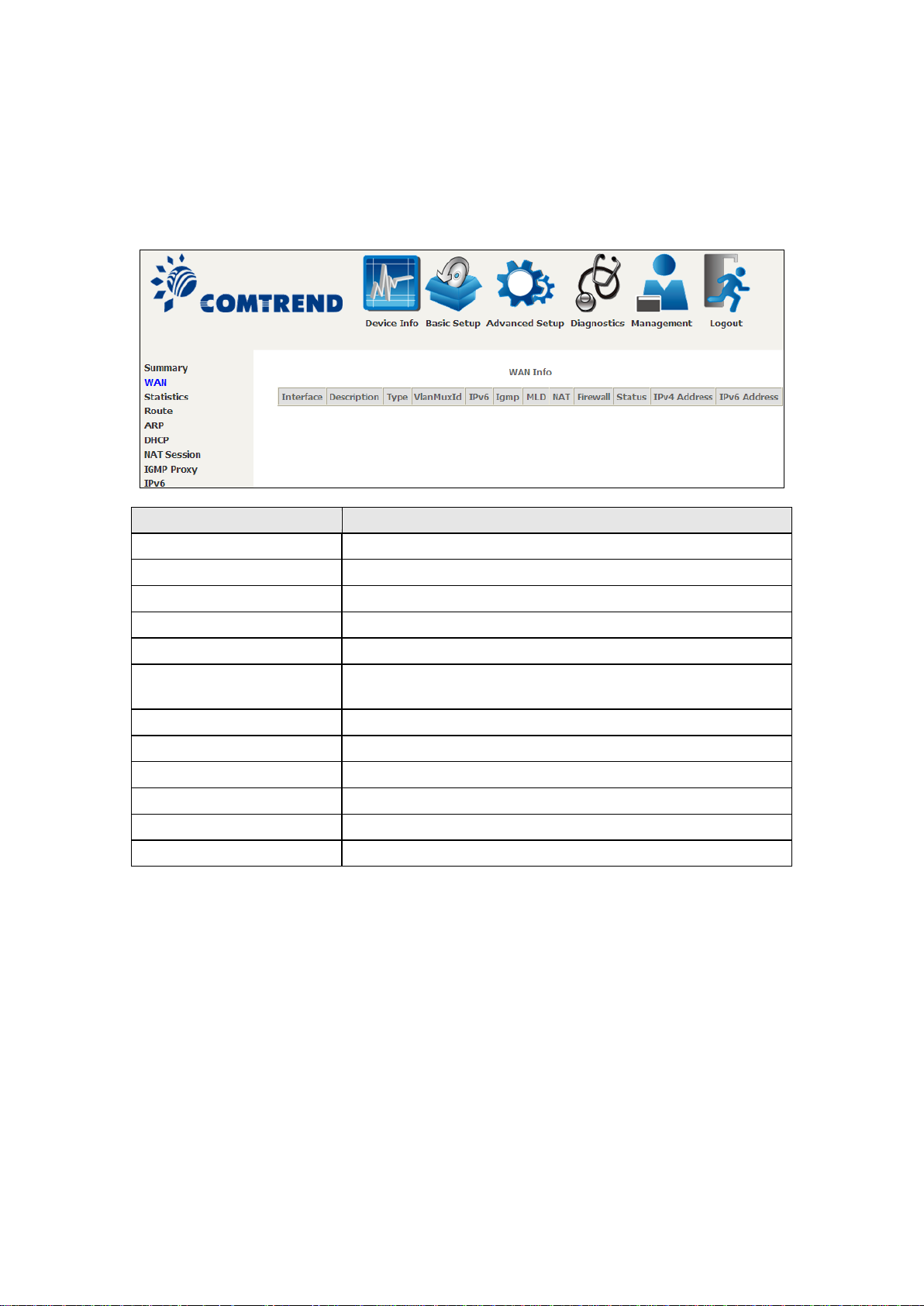
4.1 WAN
Heading
Description
Interface
Name of the interface for WAN
Description
Name of the WAN con nection
Type
Shows the connectio n t ype
VlanMuxId
Shows 802.1Q VLAN ID
IPv6
Shows WAN IPv6 status
status
MLD
Shows Multicast Listener Discovery (MLD) status
NAT
Shows Network Address Translation (NAT) status
Firewall
Shows the status of Firewall
Status
Lists the status of DSL link
IPv4 Address
Shows WAN IPv4 address
IPv6 Address
Shows WAN IPv6 address
Select WAN from the Device Info submenu to display the configured PVC(s).
IGMP Shows Internet Group Management Protocol (IGMP)
Page 21
20
4.2 Statistics
Heading
Description
Interface
LAN interface(s)
Received/Transmitted: - Bytes
- Drops
Number of Bytes
Number of dropped packets
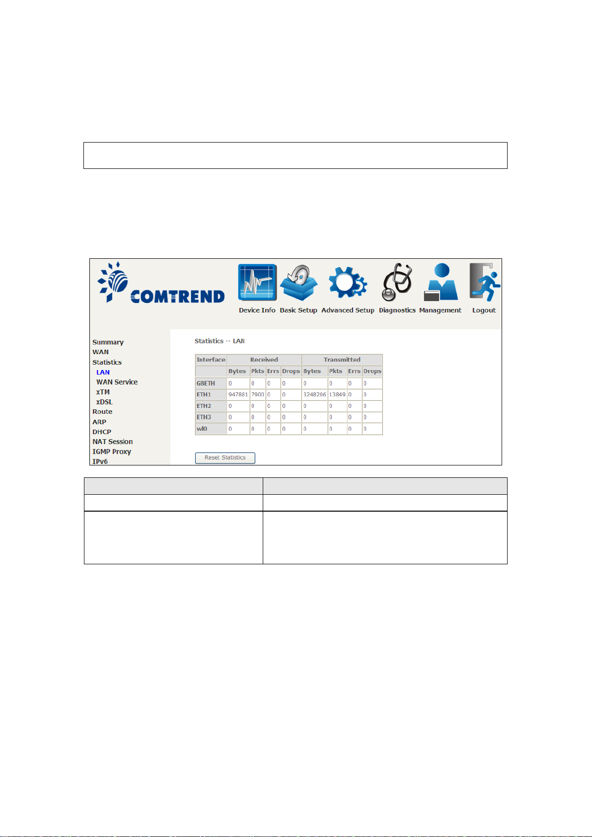
This selection provides LAN, WAN, ATM and xDSL statistics.
NOTE: These screens are updated automatically every 15 seconds.
Click Reset Statistic s to perform a manual update.
4.2.1 LAN Statistics
This screen shows data traffic statistics for each LAN interface.
- Pkts
- Errs
Number of Packets
Number of packets with errors
Page 22
21
4.2.2 WAN Service
Heading
Description
Interface
WAN interfaces
Description
WAN service label
Received/Transmitted - Bytes
- Drops
Number of Bytes
Number of dropped packets
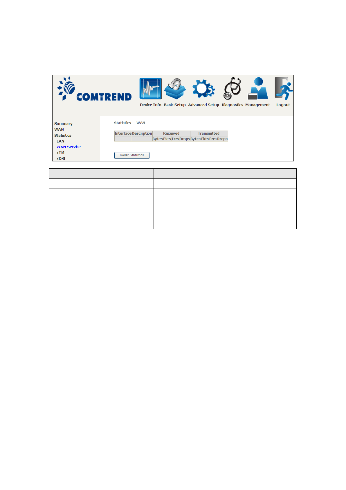
This screen shows data traffic statistics for each WAN interface.
- Pkts
- Errs
Number of Packets
Number of packets with errors
Page 23
22
4.2.3 XTM Statistics
Heading
Description
Port Number
ATM PORT (0-3)
In Octets
Number of octets received over the interface
Out Octets
Number of octets transmitted over the interface
In Packets
Number of packets received over the interface
Out Packets
Number of packets transmitted over the interface
In OAM Cells
Number of OAM Cells received over the interface
Out OAM Cells
Number of OAM Cells transmitted over the interface.
In ASM Cells
Number of ASM Cells received over the interface
Out ASM Cells
Number of ASM Cells transmitted over the interface
In Packet
Errors
Number of packets in Error
In Cell Errors
Number of cells in Error
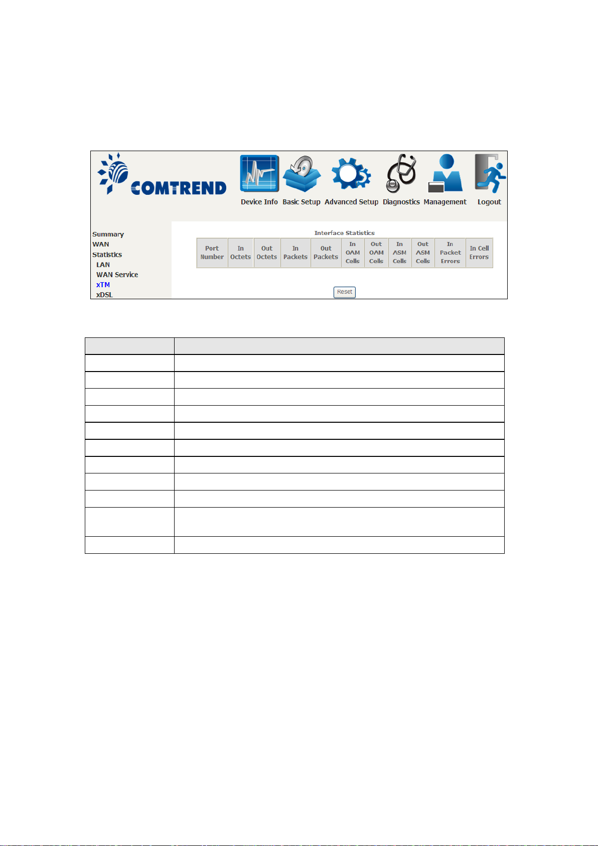
The following figure shows ATM (Asynchronous Transfer Mode)/PTM (Packet
Transfer Mode) statistics.
XTM Interface Statistics
Page 24
23
4.2.4 xDSL Statistics
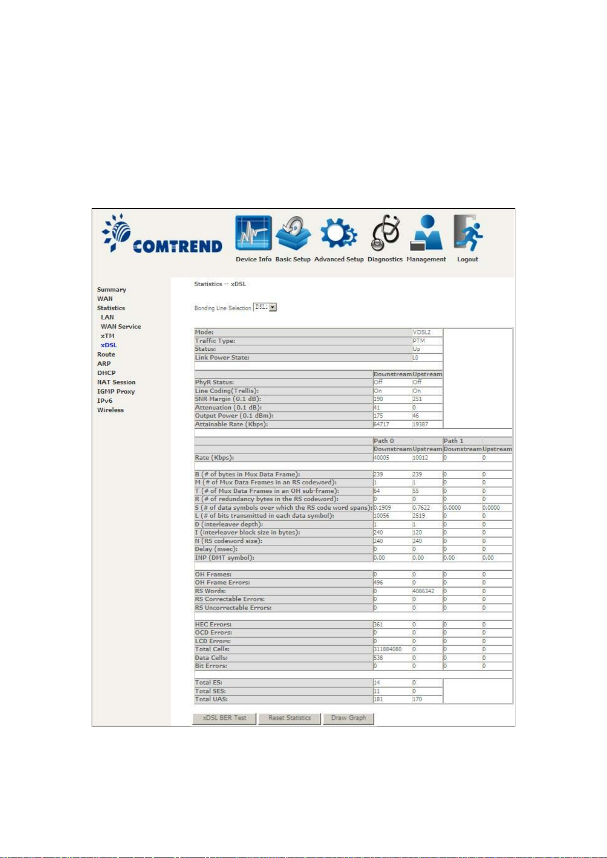
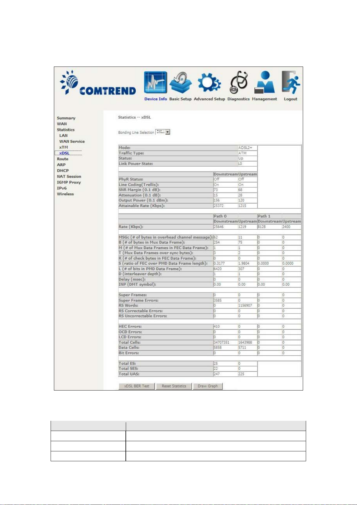
The xDSL Statistics screen displays information corresponding to the xDSL type.
The two examples below (VDSL & ADSL) show this variation.
VDSL
Page 25
24
ADSL
Field
Description
Mode
VDSL, VDSL2
Traffic Type
ATM, PTM
Status
Lists the status of the DSL link
Click the Reset Statistics button to refresh this screen.
Page 26

25
Field
Description
Link Power State
Link output power state.
Line Coding (Trellis)
Trellis On/Off
SNR Margin (0.1 dB)
Signal to Noise Ratio (SNR) margin
Attenuation (0.1 dB) Estimate of average loop attenuation in the downstream
direction.
(0.1 dBm)
Attainable Rate (Kbps)
The sync rate you would obtain.
Rate (Kbps)
Current sync rates downstream/upstream
B
Number of bytes in Mux Data Frame
M
Number of Mux Data Frames in a RS codeword
T
Number of Mux Data Frames in an OH sub-frame
R
Number of redundancy bytes in the RS codeword
S
Number of data symbols the RS codeword spans
L
Number of bits transmitted in each data symbol
D
The interleaver depth
I
The interleaver block size in bytes
N
RS codeword size
Delay
The delay in milliseconds (msec)
INP
DMT symbol
OH Frames
Total number of OH frames
OH Frame Errors
Number of OH frames received with errors
RS Words
Total number of Reed-Solomon code errors
RS Correctable Errors
Total Number of RS with correctable errors
RS Uncorrectable
Errors
Total Number of RS words with uncorrectable errors
HEC Errors
Total Number of Header Error Checksum errors
OCD Errors
Total Number of Out-of-Cell Delineation errors
LCD Errors
Total number of Loss of Cel l Delineation
Total Cells
Total number of ATM cells (including idle + data cells)
Data Cells
Total number of ATM data cells
Bit Errors
Total number of bit errors
Total ES
Total Number of Errored Seconds
Total SES
Total Number of Severely Errored Seconds
Total UAS
Total Number of Unavailable Seconds
Output Power
In VDSL mode, the following section is inserted.
Total upstream output power
Page 27
26
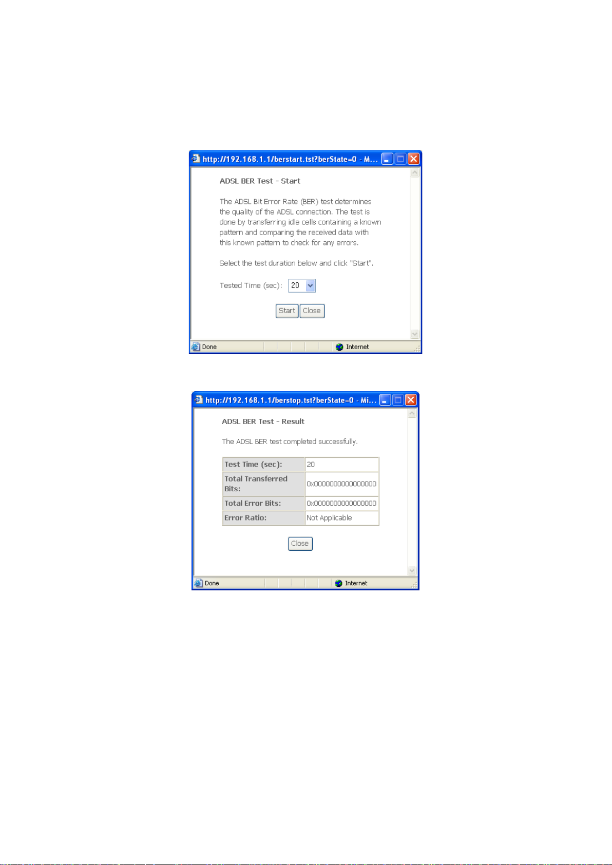
xDSL BER TEST
Click xDSL BER Test on the xDSL Statistics screen to test the Bit Error Rate (BER).
A small pop-up window will open after the button is pressed, as shown below.
Click Start to start the test or click Close to cance l the test. After the BER testing is
complete, the pop-up window will display as follows.
Page 28
27
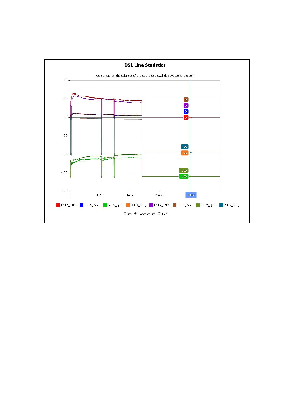
xDSL TONE GRAPH
Click Draw Tone Graph on the xDSL Statistics screen and a pop-up window will
display the xDSL bits per tone status, as s hown below.
Page 29
28
Field
Description
Destination
Destination network or destination host
Gateway
Next hop IP address
Subnet Mask
Subnet Mask of Destination
Flag
U: route is up
M: modified from routing daemon or redirect
Metric
The 'distance' to the target (usually counted in hops). It is not
used by recent kernels, but may be needed by routing daemons.
Service
Shows the WA N connection label
Interface
Shows connection interfaces
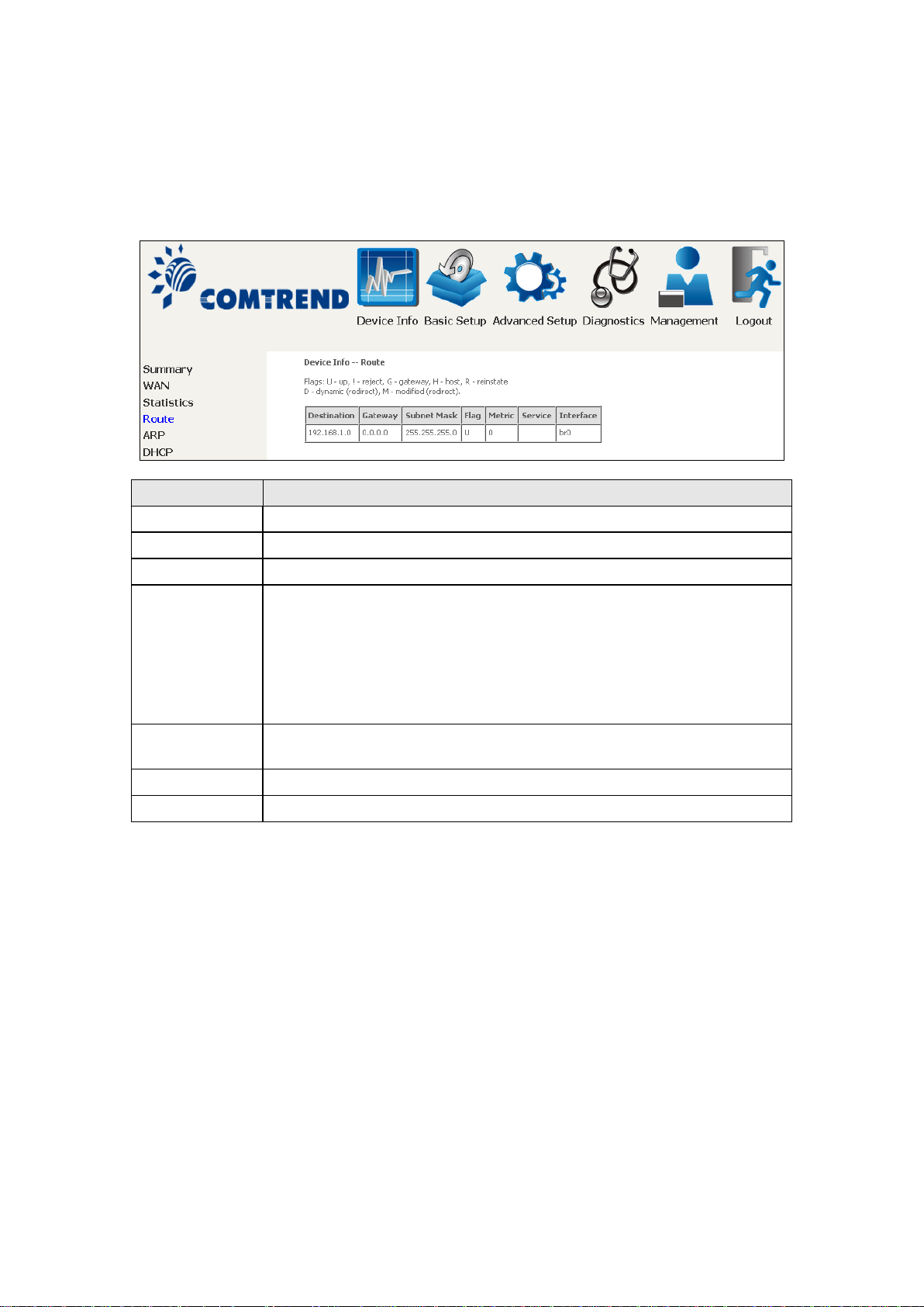
4.3 Route
Choose Route to display the routes that the NexusLink 3112u has found.
!: reject route
G: use gateway
H: target is a host
R: reinstate route for dynamic routing
D: dynamically installed by daemon or redirect
Page 30
29
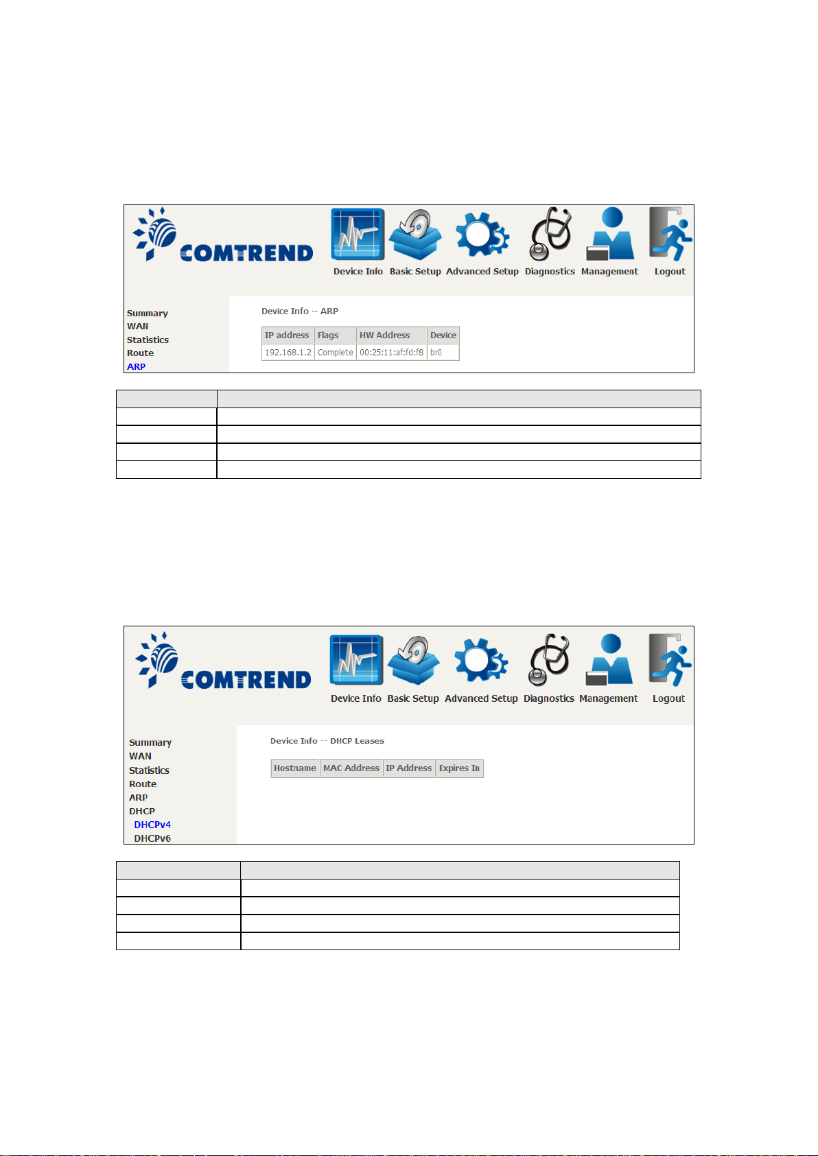
4.4 ARP
Field
Description
IP address
Shows IP address of host pc
Flags
Complete, Inc omp lete, Permanent, or Pub l ish
HW Address
Shows the MAC address of host pc
Device
Shows the connectio n interface
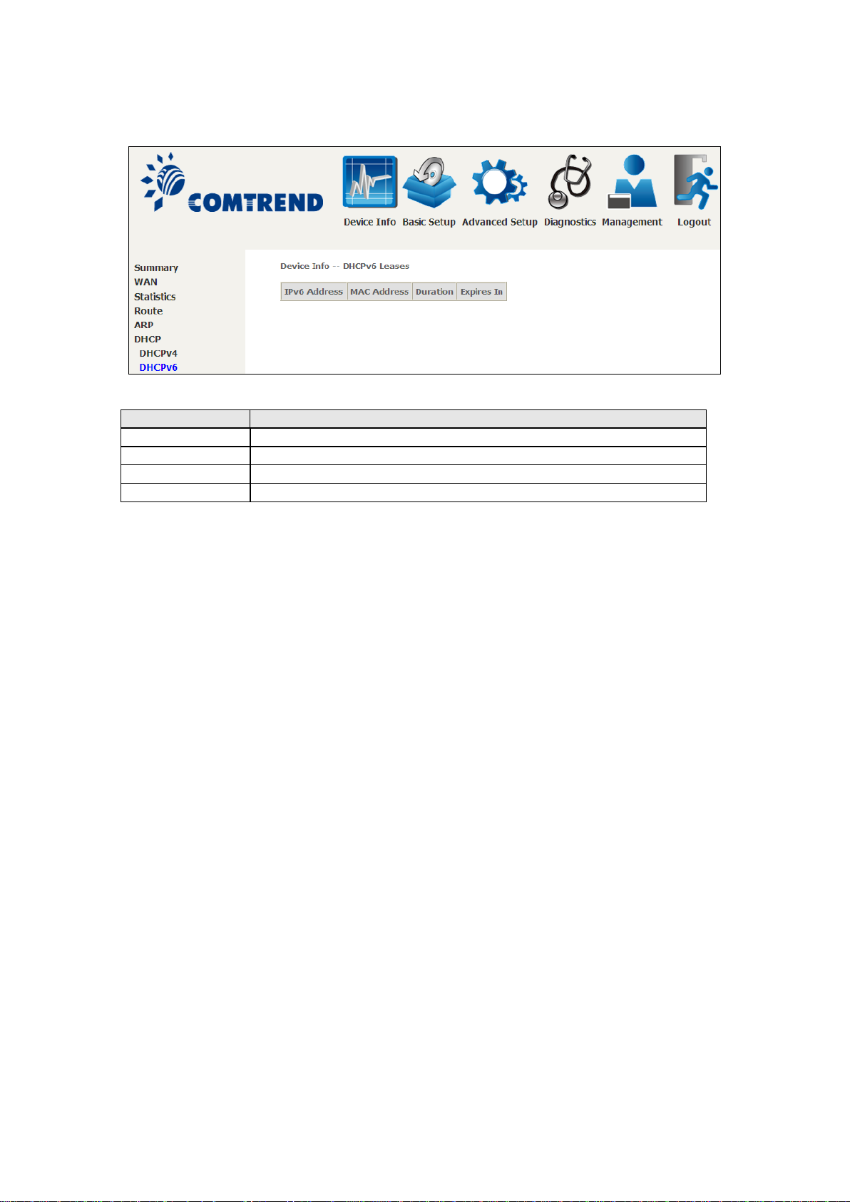
Field
Description
IPv6 Address
Shows IP address of device/host/PC
MAC Address
Shows the Ethernet MAC address of the device /host/PC
IP Address
Shows IP address of device/host/PC
Expires In
Shows how much time is left for each DHCP Lease
Click ARP to display the ARP information.
4.5 DHCP
Click DHCP to display all DHCP Leases.
Page 31
30
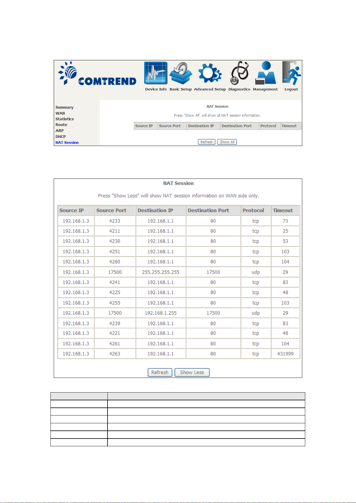
Field
Description
IPv6 Address
Shows IP address of device/host/PC
MAC Address
Shows the Ethernet MAC address of the device /host/PC
Duration
Shows leased time in hours
Expires In
Shows how much time is left for each DHCP Lease
Page 32
31
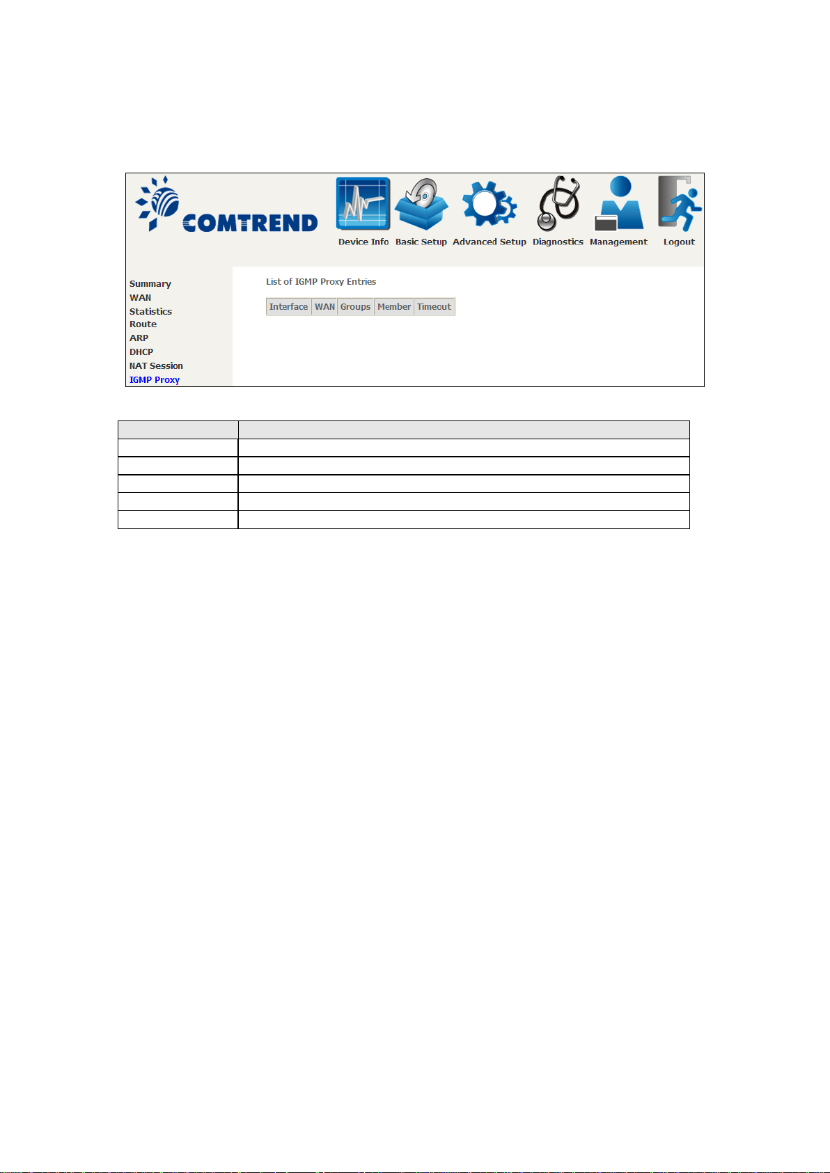
4.6 NAT Session
Field
Description
Source IP
The source IP from w h ich t he NAT session is established
Source Port
The source port from which the NAT session is established
Destination IP
The IP which the NAT session was connected to
Destination Port
The port which the N AT session was connected to
Protocol
The Protocol used in establishing the particular NAT session
Timeout
The time remaining for the TCP/UDP connection to be active
Click the “Show All” button to display the following.
Page 33
32
4.7 IGMP Proxy
Field
Description
Interface
The Source interface from which the IGMP report was received
WAN
The WAN interface from which the multicast traffic is received
Groups
The destination IGMP group address
Member
The Source IP from which the IGMP report was received
Timeout
The time remaining before the IGMP report expires
Page 34
33
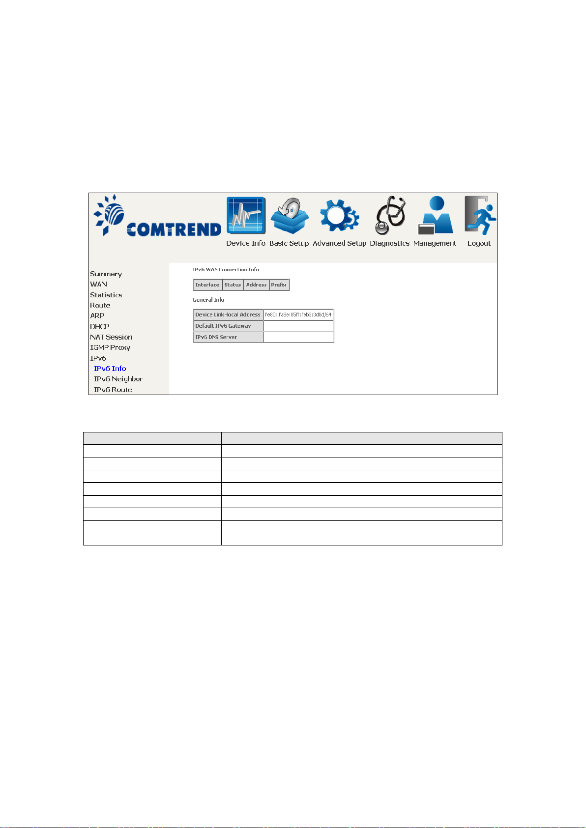
4.8 IPv6
Field
Description
Interface
WAN interface with IPv6 enabled
Status
Connection status of the WAN interface
Address
IPv6 Address of the WAN interface
Prefix
Prefix received/configured on the WAN interface
Device Link-local Address
The CPE's LAN Address
Default IPv6 Gateway
The default WAN IPv6 gateway
IPv6 DNS Server
The IPv6 DNS servers received from the WAN interface
/ configured manua lly
4.8.1 IPv6 Info
Page 35
34
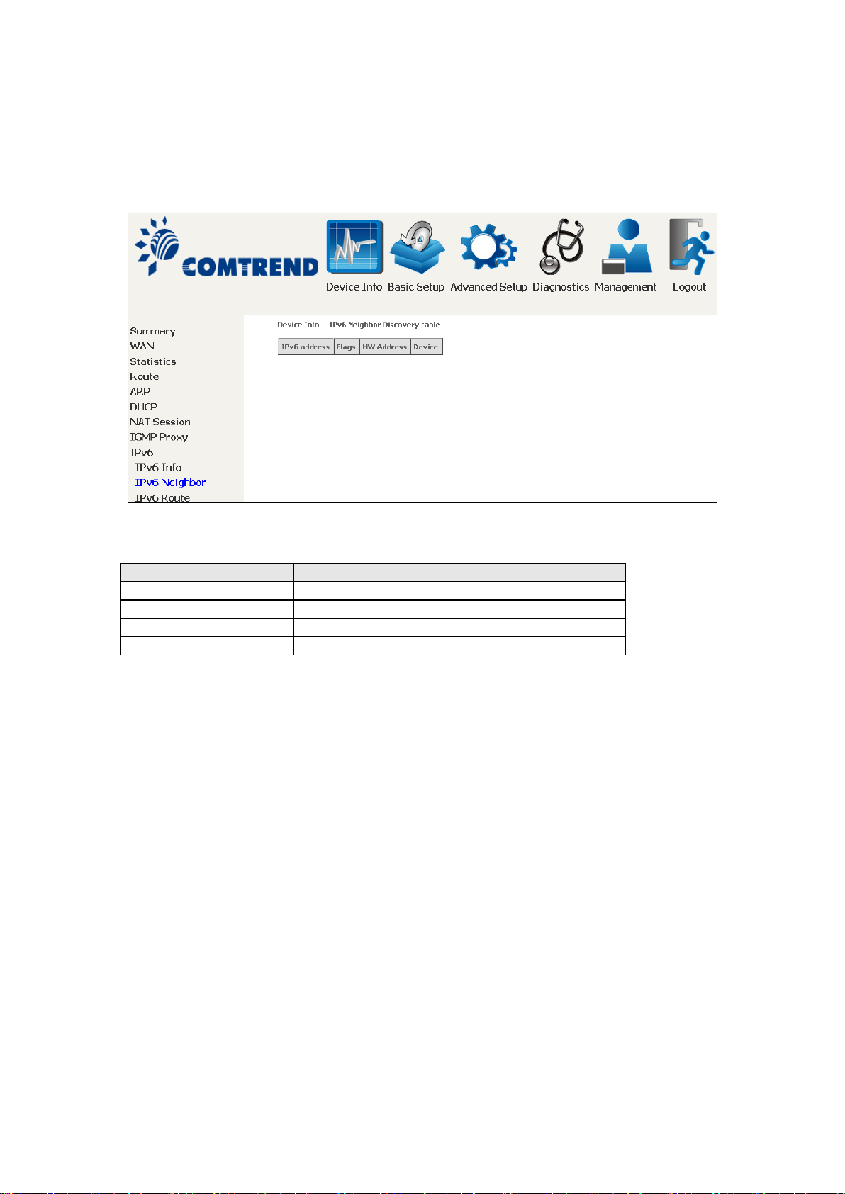
4.8.2 IPv6 Neighbor
Field
Description
IPv6 Address
Ipv6 address of the device(s) found
Flags
Status of the neighbor device
HW Address
MAC address of the neighbor device
Device
Interface from which the device is located
Page 36
35
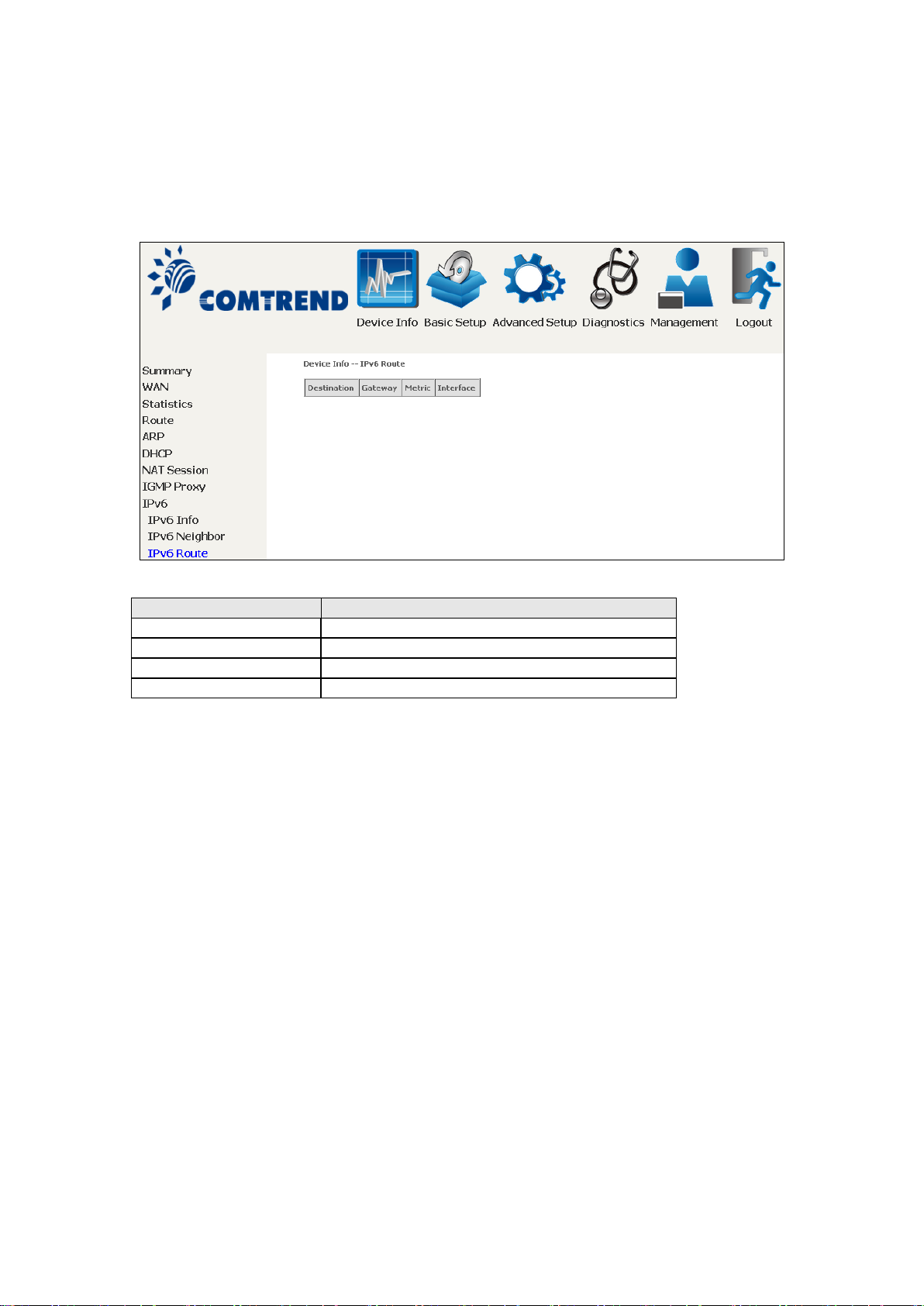
4.8.3 IPv6 Route
Field
Description
Destination
Destination IP Address
Gateway
Gateway address used for destination IP
Metric
Metric specified for gateway
Interface
Interface used for destination IP
Page 37
36
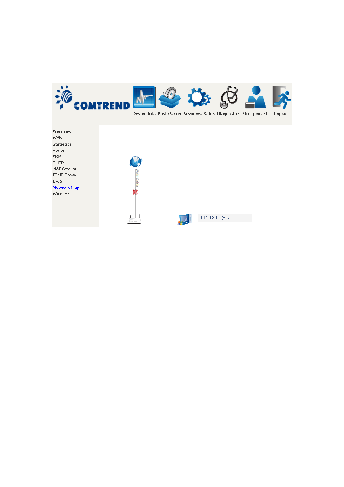
4.9 Network Map
The network map feature provides an illustration of connected devices
on the router.
The current wan status (firewall on/off) is displayed on the left side.
Detailed information of PC/USB connected to the router is shown on
the right side.
Page 38
37
Field
Description
MAC
Lists the MAC address of all the stations.
Associated
Lists all the stations that are associated with the Access
tion. I f a stat ion is id le for
too long, it is removed from this lis t.
Authorized
Lists those devices with authorized access.
SSID
Lists which SSID of the mode m that the stations conne ct
to.
Interface
Lists which interface of the modem that the stations
connect to.
4.10 Wireless
4.10.1 Station Info
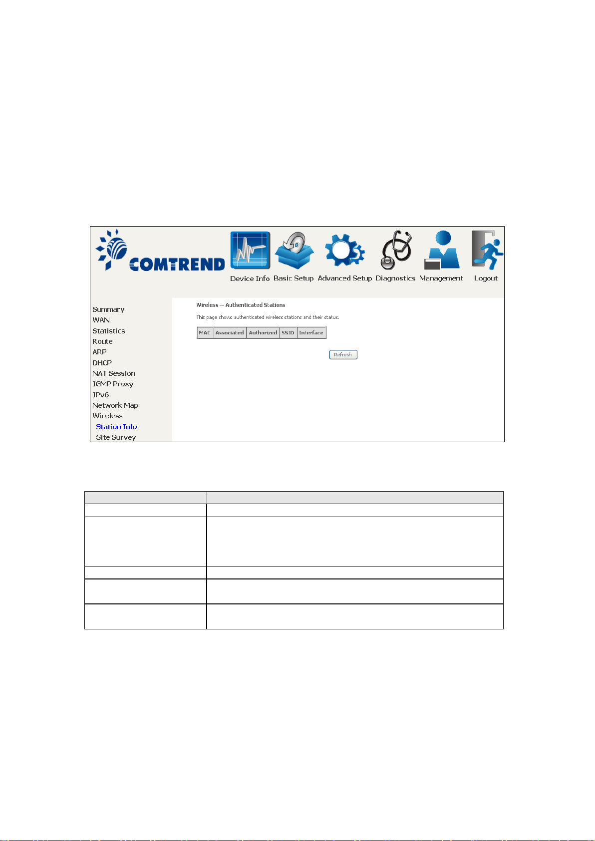
This page shows authenticated wireles s stations and their status. Click the Refresh
button to update the list of stations in the WLAN.
Consult the table below for descriptions of each column heading.
Point, along with the amount of time since packets were
transferred to and fro m each sta
Page 39
38
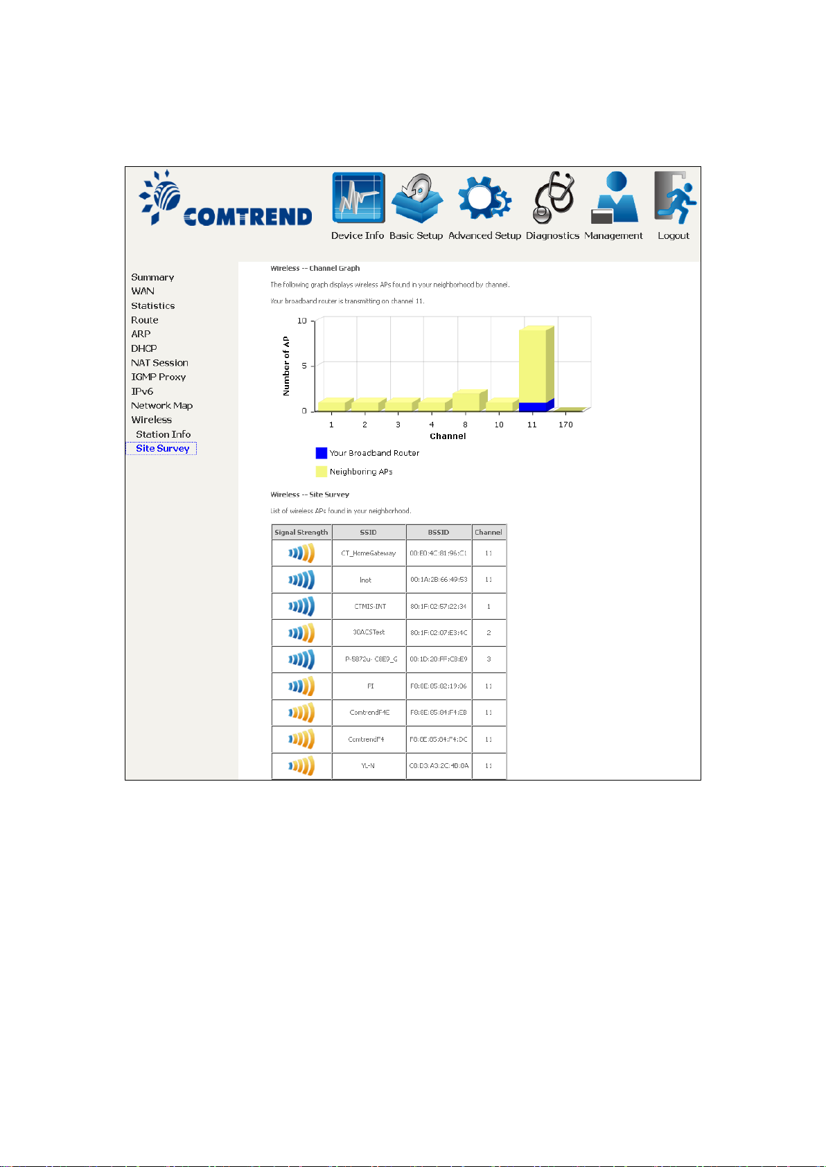
4.10.2 Site Survey
The graph displays wireless APs found in your neighborhoo d b y channel.
Page 40
39
Chapter 5 Basic Setup
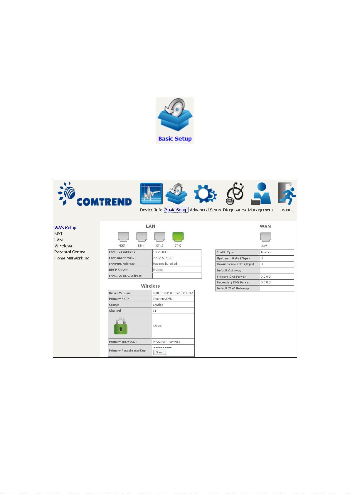
You can reach this page by clicking on the following icon located at the top of the
screen.
This will bring you to the following screen.
Page 41
40
5.1 Wan Setup
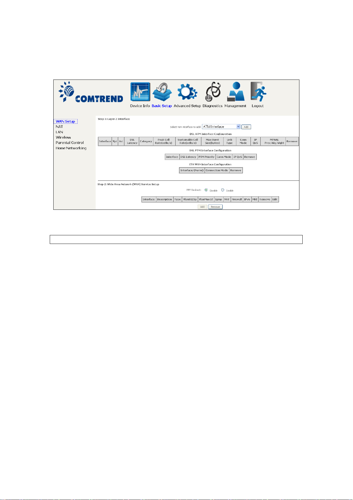
Add or remove ATM, PTM and ETH WAN interface connections here.
Click Add to create a new ATM interface (see Appendix E - Connection Setup).
NOTE: Up to 8 ATM interfaces can be created and saved in flash memory.
To remove a connection, select its Remove column radio butto n and click Remove.
Page 42
41
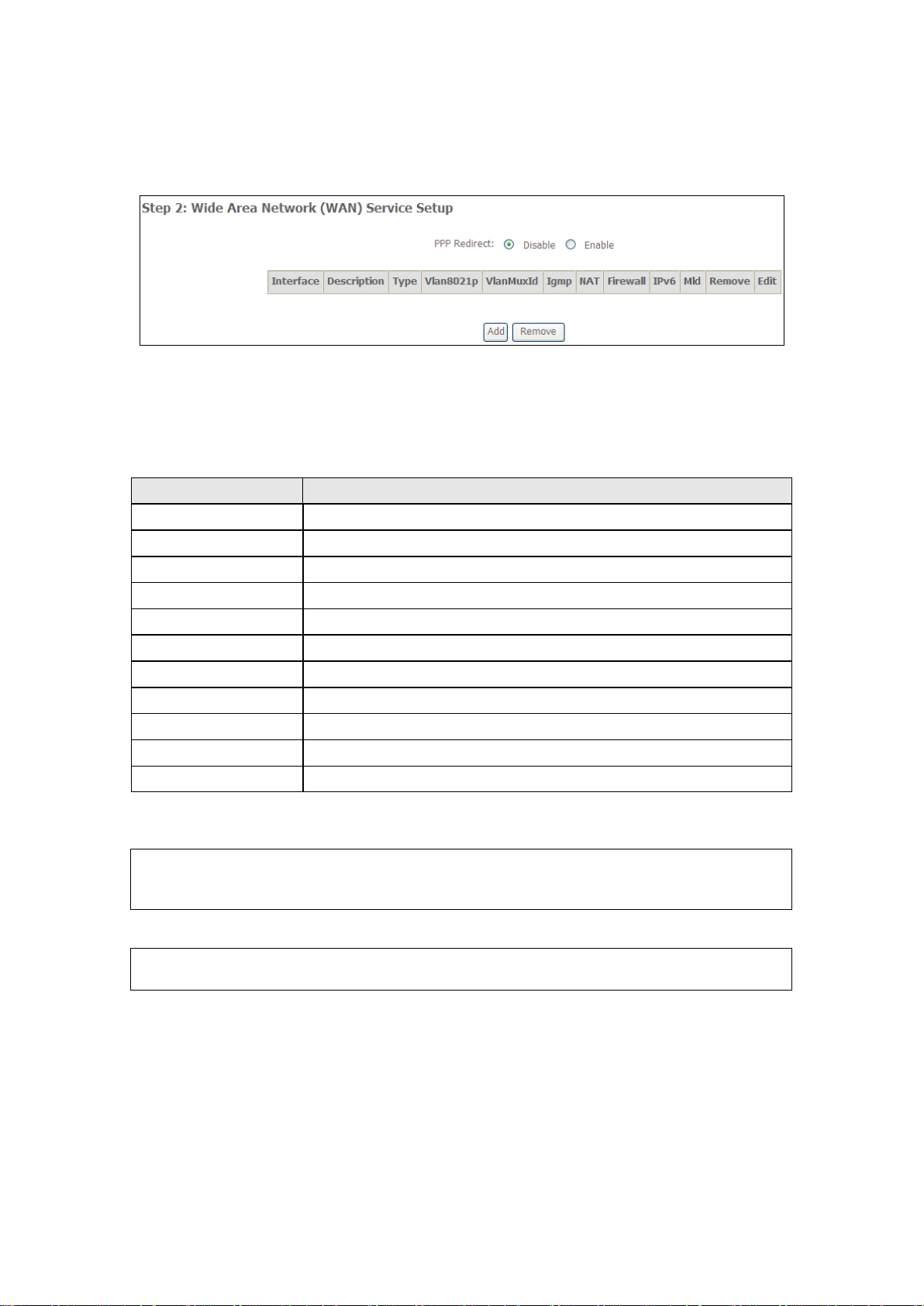
5.1.1 WAN Service Setup
Heading
Description
Interface
Name of the interface for WAN
Description
Name of the WAN connection
Type
Shows the connectio n t ype
Vlan8021p
VLAN ID is used for VLAN Tagging (IEEE 802.1Q)
VlanMuxId
Shows 802.1Q VLAN ID
IGMP
Shows Internet Group Management Protocol (IGMP) status
NAT
Shows Network Address Translation (NAT) status
Firewall
Shows the Security status
IPv6
Shows the WAN IPv6 address
MLD
Shows Multicast Listener Discovery (MLD) status
Remove
Select interfaces to remove
This screen allows for the configuration of WAN interfaces.
Click the Add button to create a ne w co nnection. For connections on ATM or ETH
WAN interfaces see Appendix E - Connection Setup.
To remove a connection, select its Remove column radio button and click Remove.
To remove a connection, select its Remove column radio button and click Remove.
NOTE: ETH and A TM serv ice connec tions c anno t c oex ist. I n De fa ult Mo de, up to
8 WAN connectio ns can be configur ed; while VLAN M ux Connection Mode
supports up to 16 WAN connections.
NOTE: Up to 16 PVC profiles can be configured and saved in flash memory.
Also, ETH and PTM/ATM service connections cannot coexist.
Page 43
42
5.2 NAT
To display this option, NAT must be enabled in at least one PVC. NAT is not an
available option in Bridge mode.
5.2.1 Virtual Servers
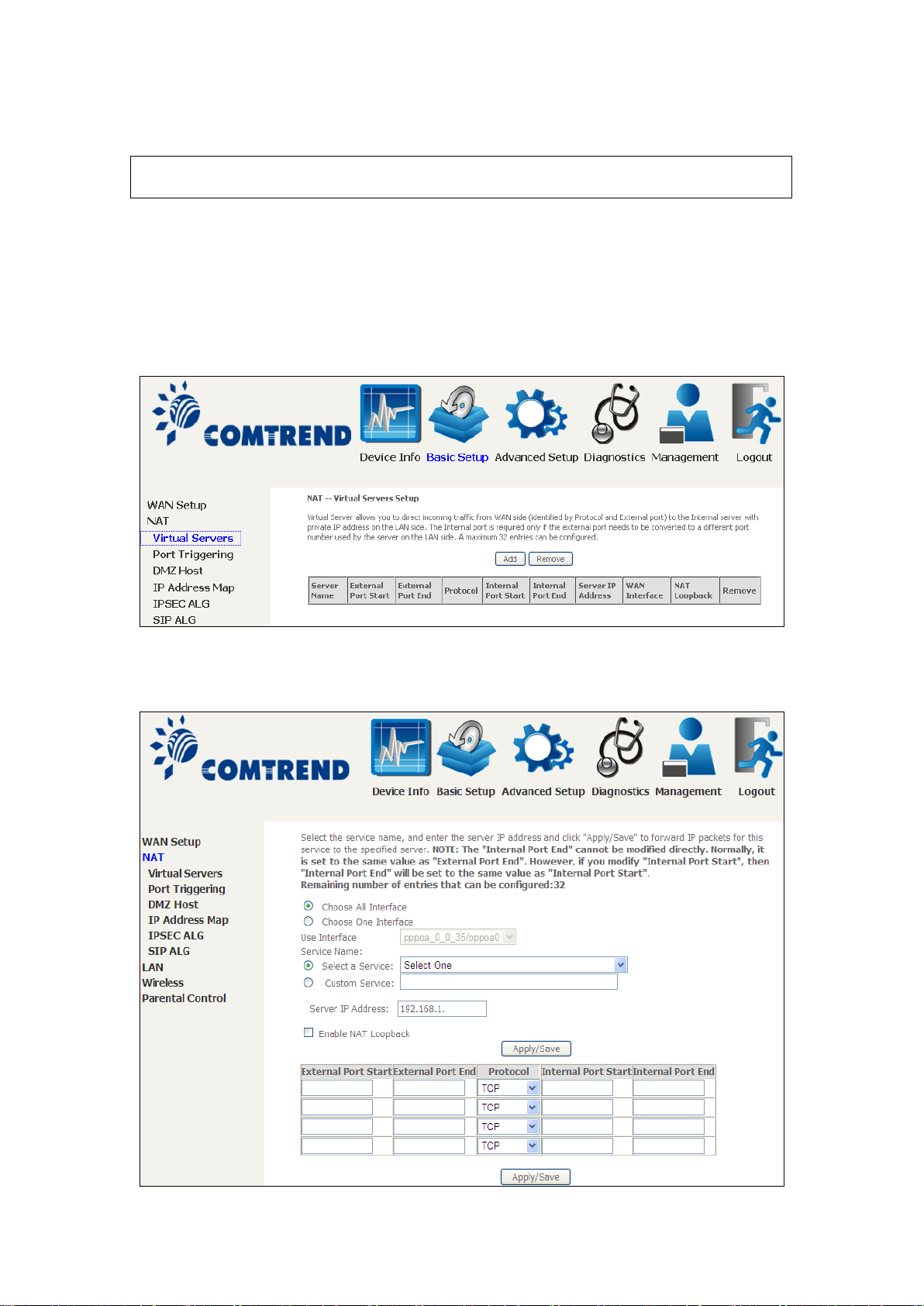
Virtual Servers allow you to direct incoming tra ffic from the W AN side (identified by
Protocol and External port) to the internal server with private IP addresses on the
LAN side. The Internal port is required only if the external port needs to be
converted to a different port number used by the server on the LAN side.
A maximum of 32 entries can be configured.
To add a Virtual Server, click Add. The following will be displa yed.
Page 44

43
Consult the table below for field and header descriptions.
Field/Header
Description
Choose One Interface
Use Interface
Select a Service
Custom Service
User should select the service from the list.
User can enter the name of their choice.
Server IP Address
Enter the IP address for the server.
Enable NAT Loopback
Allows local machines to access virtual server via WAN IP
Address
External Port Start
Enter the starting external port number (w hen you select
External Port End
Enter the ending external port number (when you select
ranges are automatically configured.
Protocol
TCP, TCP/UDP, or UDP.
Internal Port Start
Enter the internal port starting number (when you select
are automatically configured
Internal Port End
Enter the internal port ending number (when y ou select
ranges are automatically configured.
Choose All Interface Virtual server rules will be created for all WAN interfaces.
Or
Select a WAN interface from the drop-down box.
Or
Custom Server). When a service is selected, the port
ranges are automatically configured.
Custom Server). When a service is selected, the port
Custom Server). When a service is selected the port ranges
Custom Server). When a service is selected, the port
Page 45
44
5.2.2 Port Triggering
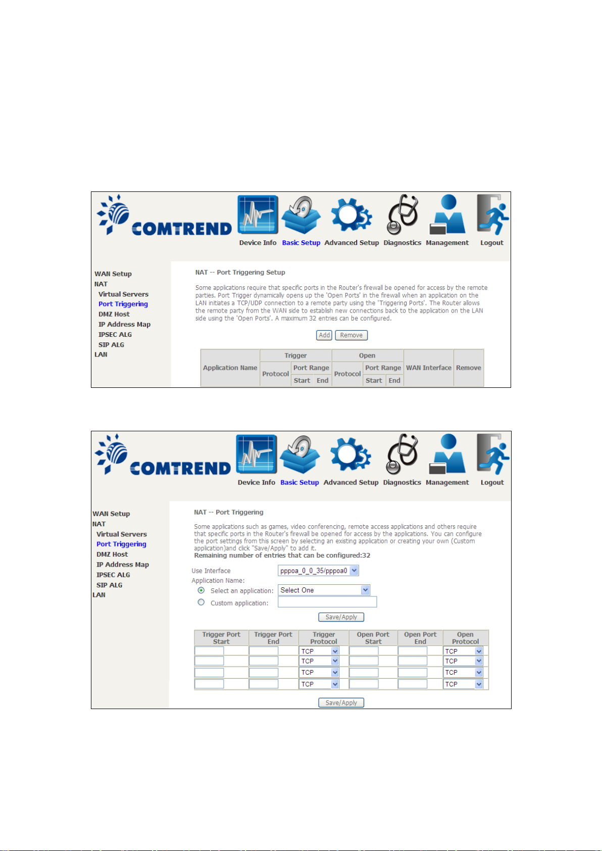
Some applications require that specific ports in the firewall be opened for access by
the remote parties. Port Triggers dynamically 'Open Ports' in the firewall when an
application on the LAN initiates a TCP/UDP connection to a remote party using the
'Triggering Ports'. The Router allows the remote party from the WAN side to
establish new connections back to the applicatio n on the LAN side using the 'Open
Ports'. A maximum 32 entries can be configured.
To add a Trigger Port, click Add. The f ollowing will b e displaye d.
Click Save/Apply to save and apply the settings.
Consult the table below for field and heade r descriptions.
Page 46

45
Field/Header
Description
Use Interface
Select a WAN interface from the drop-down box.
Select an Application
User should select the application from the list.
Trigger Port Start
Enter the starting trigger port number (whe n you select
port ranges are automatically configured.
Trigger Port End
Enter the ending trigger port number (when you select
port ranges are automatically configured.
Trigger Protocol
TCP, TCP/UDP, or UDP.
Open Port Start
Enter the starting open port number (when you select
port ranges are automatically configured.
Open Port End
Enter the ending open port number (when you select
port ranges are automatically configured.
Open Protocol
TCP, TCP/UDP, or UDP.
Or
Custom Application
Or
User can enter the name of their choice.
custom application). When an application is selected, the
custom application). When an application is selected, the
custom application). When an application is selected, the
custom application). When an application is selected, the
Page 47
46
5.2.3 DMZ Host
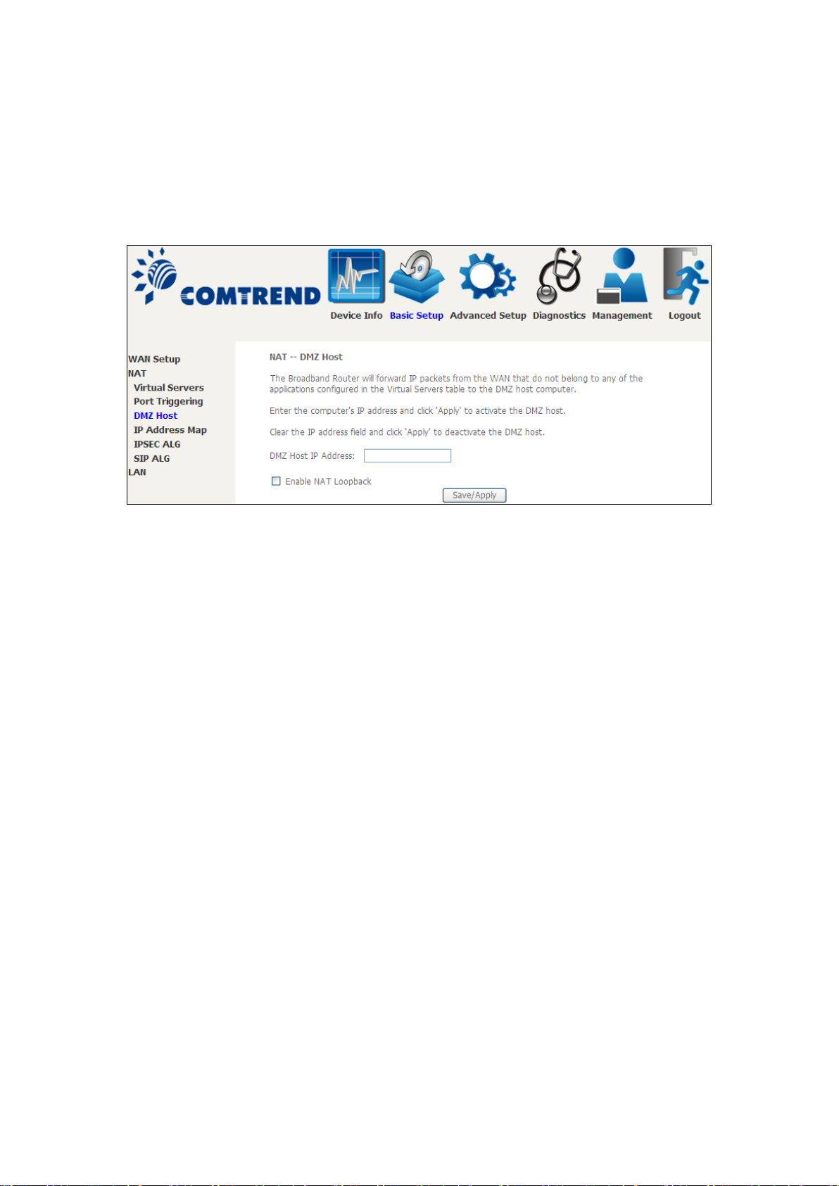
The DSL router will forward IP packets from the WAN that do not belong to any of
the applications configured in the Virtual Servers table to the DMZ host computer.
To Activate the DMZ host, enter the DMZ host IP address and click Save/Apply.
To Deactivate the DMZ host, clear the IP address field and click Save/Apply.
Enable NAT Loopback allows PC on the LAN side to access servers in the LAN
network via the router’s WAN IP.
Page 48
47
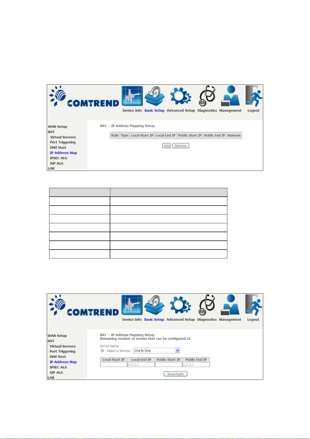
5.2.4 IP Address Map
Field/Header
Description
Rule
The number of the rule
Type
Mapping type from local to public.
Local Start IP
The beginning of the local IP
Local End IP
The ending of the loc al IP
Public Start IP
The beginning of the public IP
Public End IP
The ending of the public IP
Remove
Remove this rule
Mapping Local IP (LAN IP) to some specified Public IP (WAN IP).
Click the Add button to display the following.
Select a Service, then click the Save/Apply button.
Page 49

48
One to One: mapping one local IP to a specific public IP
Many to one: mapping a range of local IP to a specific public IP
Many to many(Overload): mapping a range of local IP to a different range of
public IP
Many to many(No Overload): mapping a range of local IP to a same range of
public IP
Page 50
49
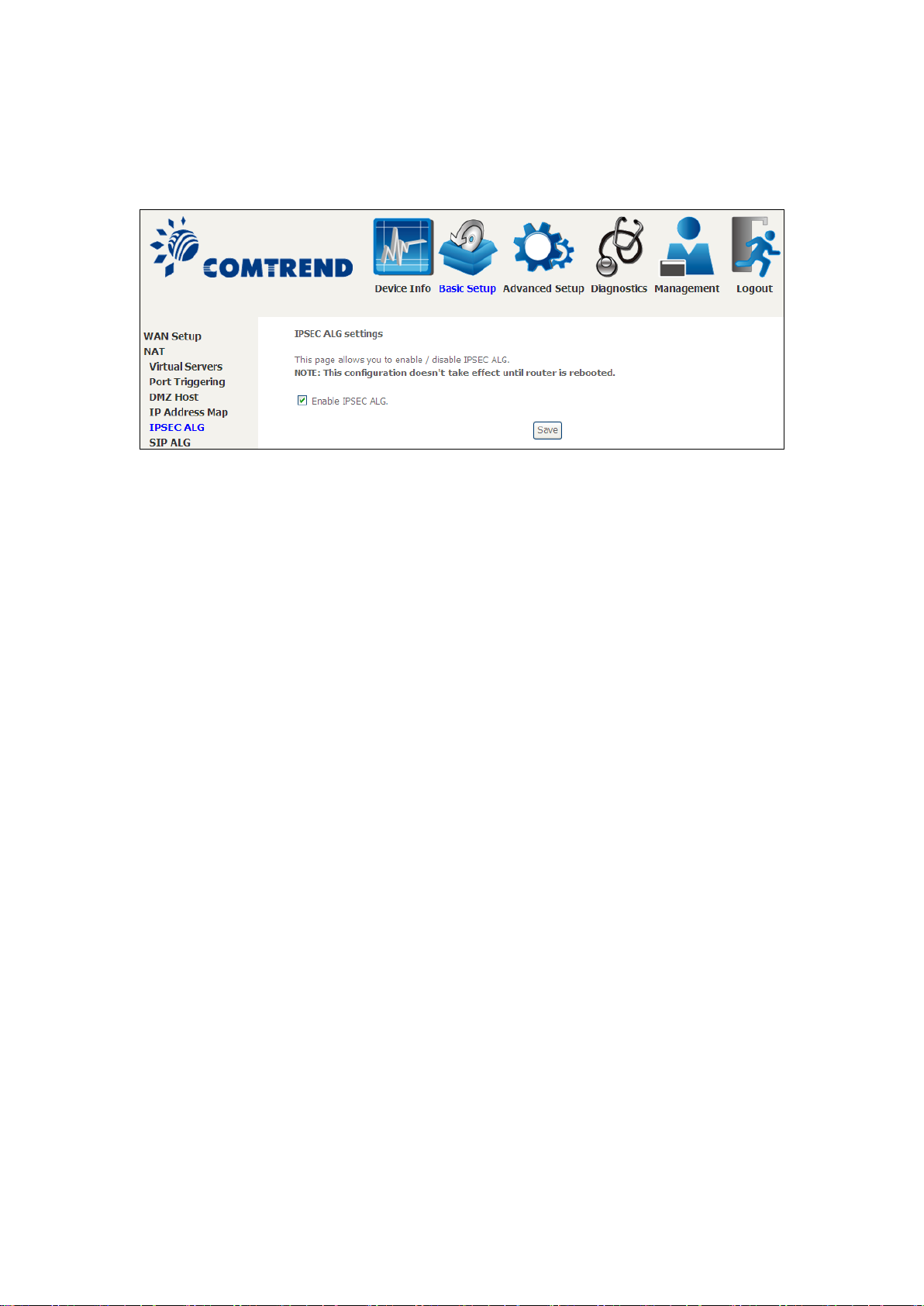
5.2.5 IPSEC ALG
IPSEC ALG provides multiple VPN passthrough connection support, allowing
different clients on LAN side to e stablish a s ecured IP Connec tion to the W AN server .
To enable IPSEC ALG, tick the checkbox and click the Save button.
Page 51
50
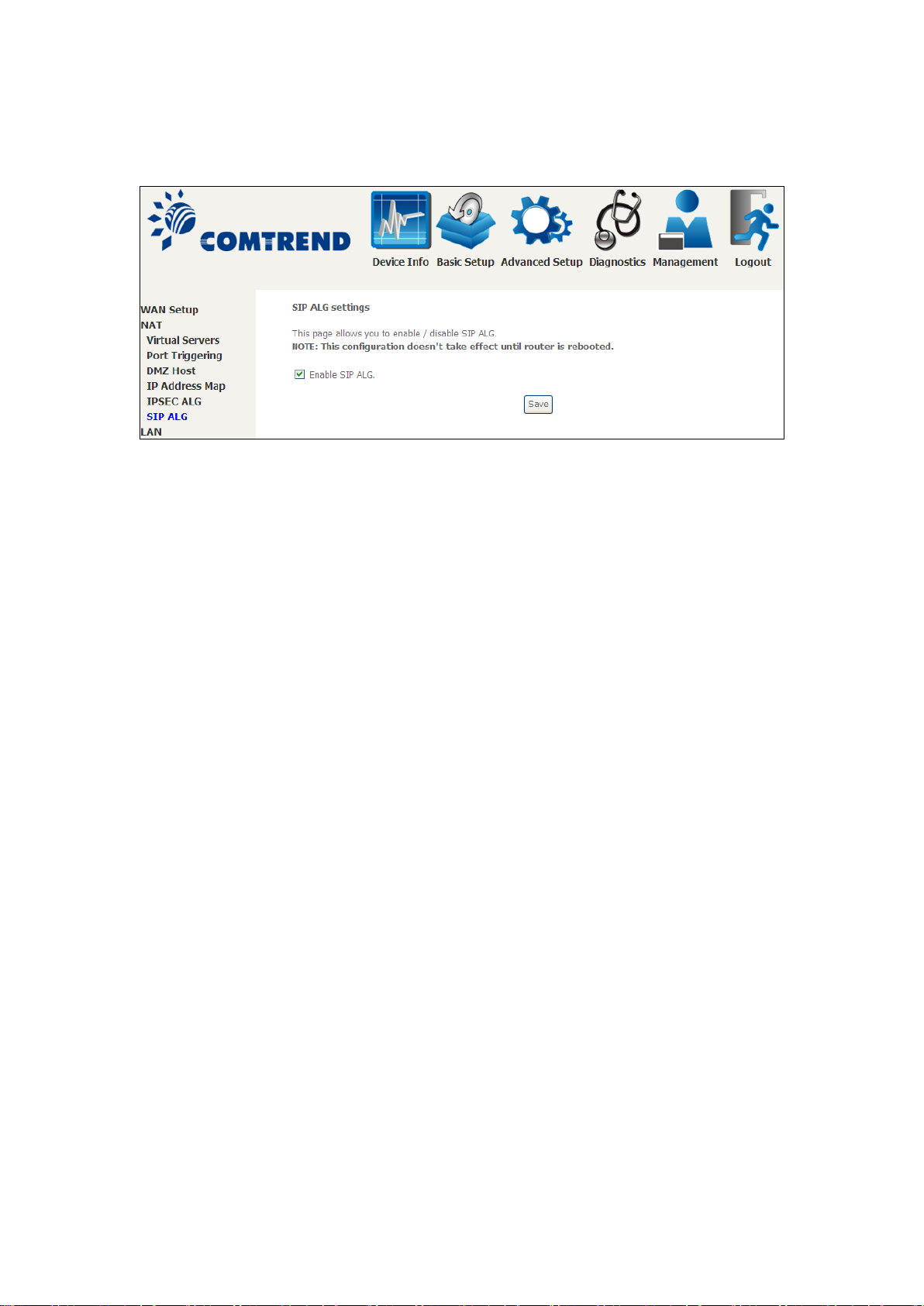
5.2.6 SIP ALG
This page allows you to enable / disable SIP A LG.
Page 52
51
5.3 LAN
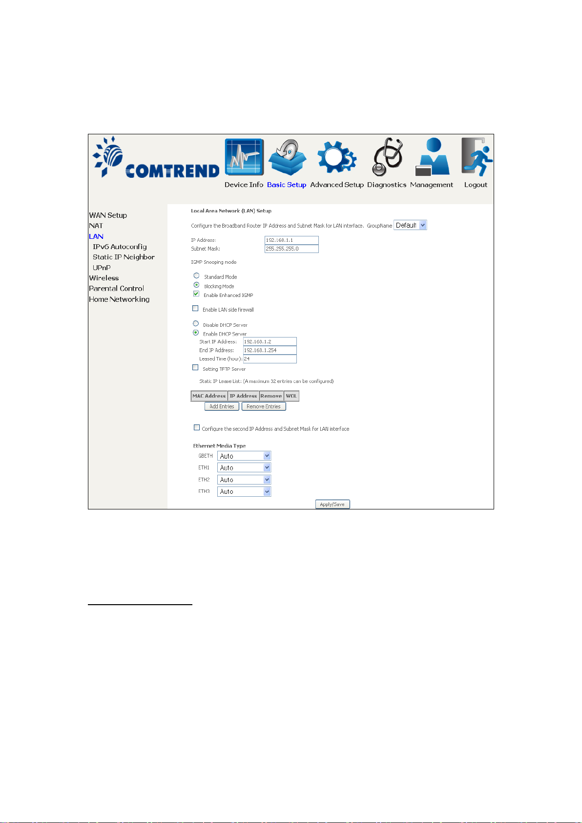
Configure the LAN interface settings and then click Apply/Save.
Consult the field descriptions below for more details.
GroupName: Select an Interface Group.
1st LAN INTERFACE
IP Address: Enter the IP address for the LAN port.
Subnet Mask: Enter the subnet mask for the LAN port.
IGMP Snooping:
Standard Mode: In standard mode, multic ast traffic will flood to all
bridge ports when no client subscribes to a multicast
group – even if IGMP snooping is enabled.
Page 53
52
Blocking Mode: In blocking mode, the multicast data traffic will be
blocked and no t flood to all bridge po rts when there are
no client subscriptions to any multicast group.
Enable Enh anced IGMP: Enable by ticking the checkbox . IGMP packets
between LAN ports will be blocked.
Enable LAN side firewall: Enable by ticking the checkbox .
DHCP Server: To enable DHCP, select Enable DHCP server and enter Start and
End IP addresses and the L eased Time. This se tting configures the
router to automatically assign IP, default gateway and DNS server
addresses to every PC on your LAN.
Setting TFTP Server: Enable by ticking the checkbox . Then, input the TFTP
server address or an IP ad d re ss.
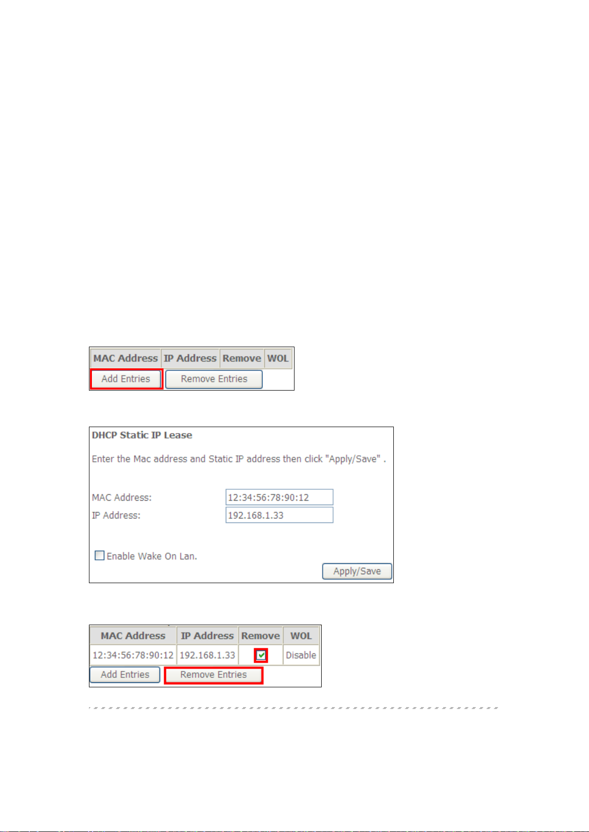
Static IP Lease List: A maximum of 32 entries can be configured.
To add an entry, enter MAC address and Static IP address and then click
Apply/Save.
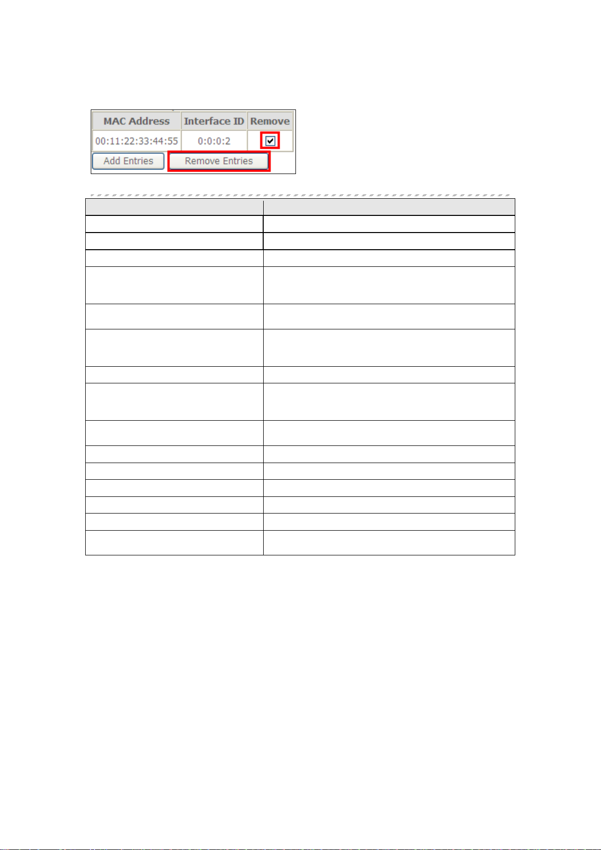
To remove an entry, tick the corresponding checkbox in the Remove column and
then click the Remove Entries button, as shown below.
Page 54
53
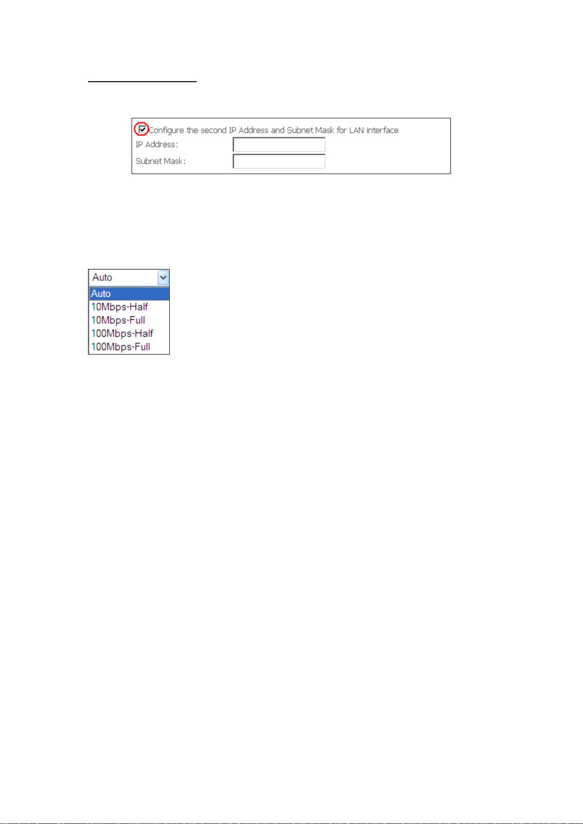
2ND LAN INTERFACE
To configure a secondary IP address, tick the checkbox outlined (in RED) below.
IP Address: Enter the secondary IP address for the LAN port.
Subnet Mask: Enter the secondary subnet ma sk for the LAN port.
Ethernet Media Type:
Configure auto negotiation, or enforce selected speed and duplex mode for the
Ethernet ports.
Page 55
54
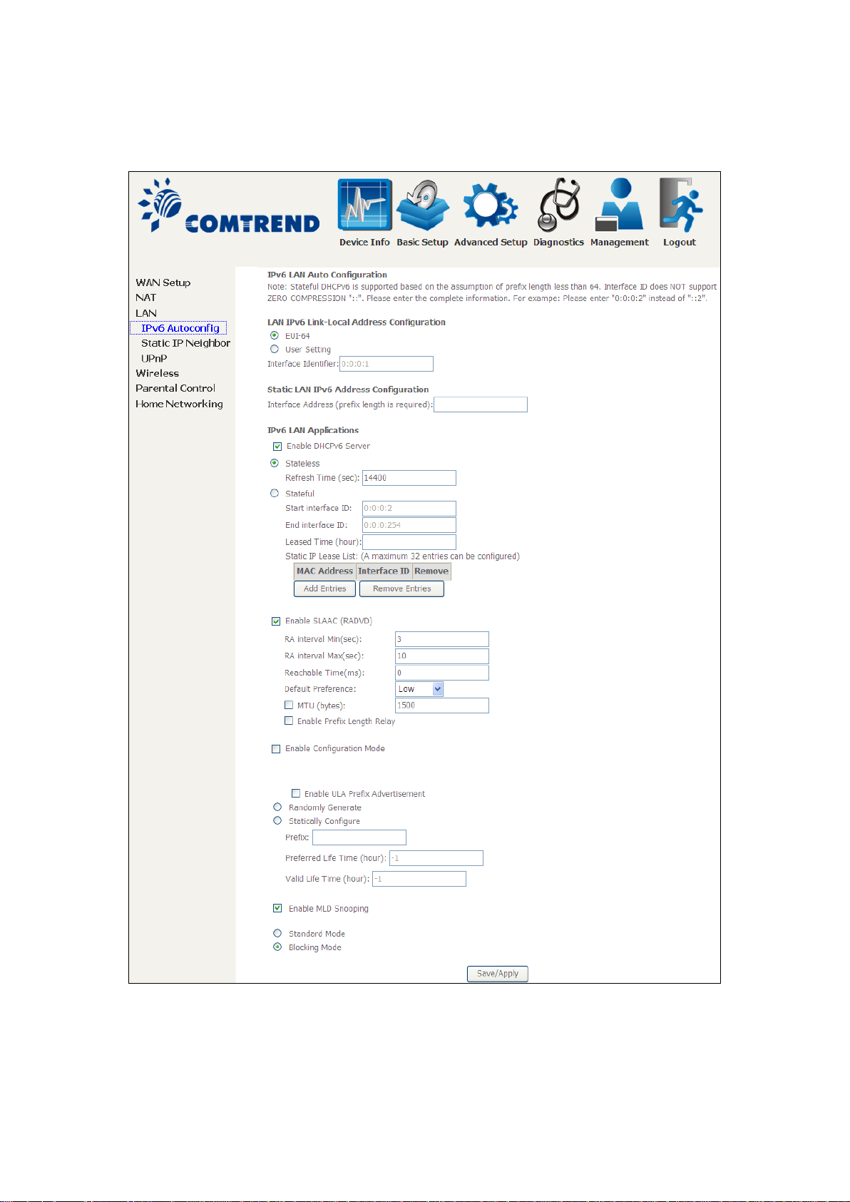
5.3.1 LAN IPv6 Autoconfig
Configure the LAN interface settings and then click Save/Apply.
Consult the field descriptions below for more details.
Page 56
55
LAN IPv6 Link-Local Address Configuration
Heading
Description
EUI-64
Use EUI-64 algorithm to calculate link-local address from MAC
address
User Setting
Use the Interface Identifier field to define a link-local address
Heading
Description
Interface Address
required):
Configure static LAN IPv6 address and subnet prefix
Heading
Description
Stateless
Use stateless configuration
Refresh Time (sec):
The information refresh time option specifies how long a
from DHCPv6
Stateful
Use stateful configuratio n
Start interface ID:
Start of interface ID to be assigned to dhcpv6 client
Leased Time (hour):
Lease time for dhcpv6 client to use t he assigned IP address
Static LAN IPv6 Address Configuration
(prefix length is
IPv6 LAN Applications
End interface ID: End of interface ID to be assigned to dhcpv6 client
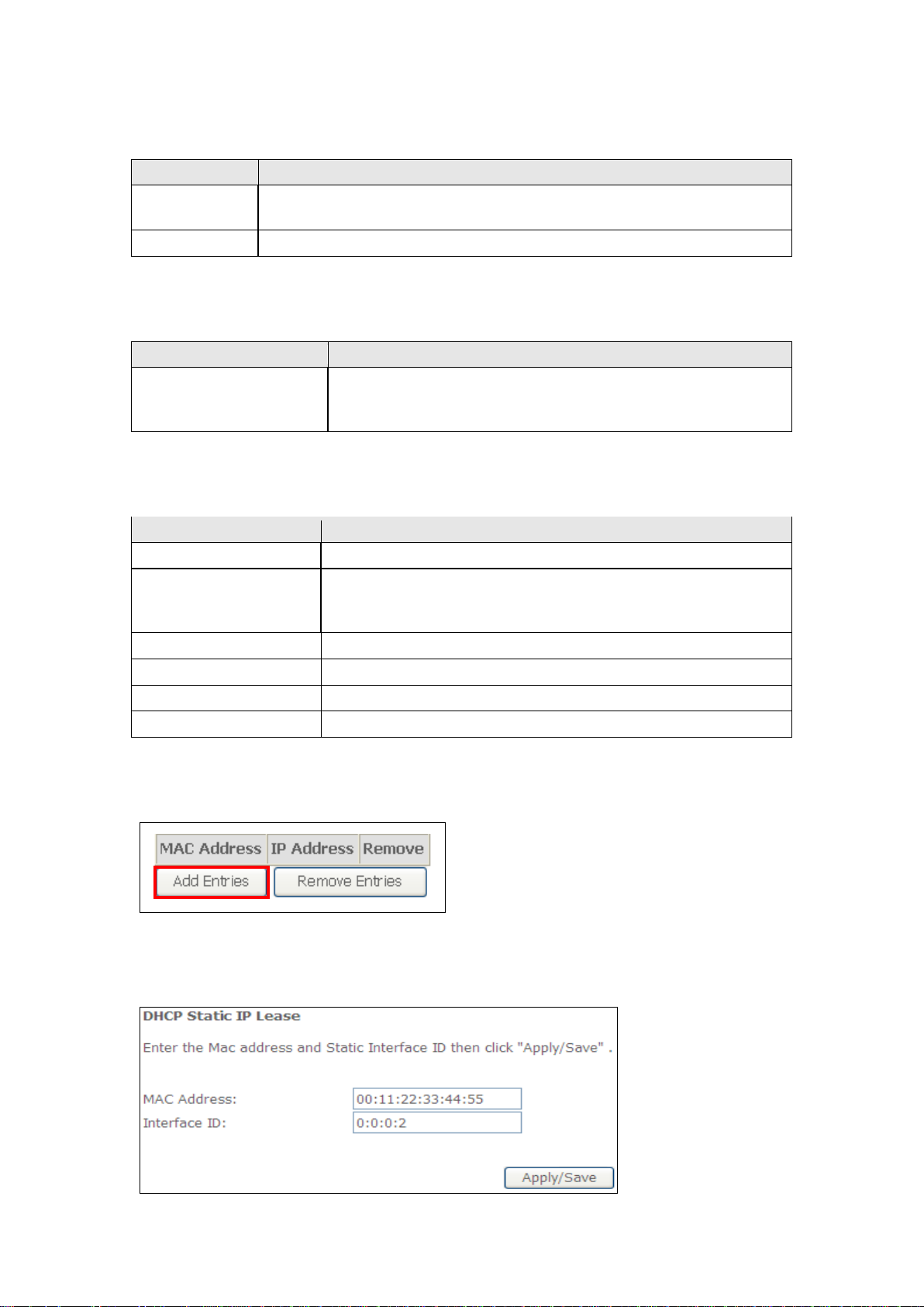
Static IP Lease List: A maximum of 32 entries can be configured.
length
client should wait before refreshing information retrieved
To add an entry, enter MAC address and Interface ID and then click Apply/Save.
Page 57
56
To remove an entry, tick the corresponding checkbox in the Re mo v e column and
Heading
Description
Enable RADVD
Enable use of router advertisement daemon
RA interval Min(sec):
Minimum time to send router advertisement
Reachable Time(ms):
The time, in milliseconds that a neighbor is
confirmation
Default Preference:
Preference level associated with the default
router
MTU (bytes):
MTU value used in router advertisement
the same MTU value
Enable Prefix Length Relay
Use prefix length receive from WAN interface
Enable Configuration Mode
Manually configure prefix, prefix length,
router advertisement
Enable ULA Prefix Advertisement
Allow RADVD to advertise Unique Local Address
Prefix
Randomly Generate
Use a Randomly Generated Prefix
Statically Configure Prefix
Specify the prefix to be used
Statically Configure
The prefix to be used
Preferred Life Time (hour)
The preferred life time for this prefix
Valid Life Time (hour)
The valid life time for this prefix
Enable MLD Snooping
Enable/disable IPv6 multicast forward to LAN
ports
then click the Remove Entries button, as shown below.
RA interval Max(sec): Maximum time to send router advertisement
reachable after receiving reachability
messages to insure t hat all nodes on a link use
preferred lifetime and valid lifetime used in
Page 58
57
5.3.2 Static IP Neighbor
Heading
Description
IP Version
The IP version used for the neighbor device
IP Address
Define the IP Address for the neighbor device
MAC Address
The MAC Address of the neighbor device
Associated Interface
The interface where the neighbor device is located
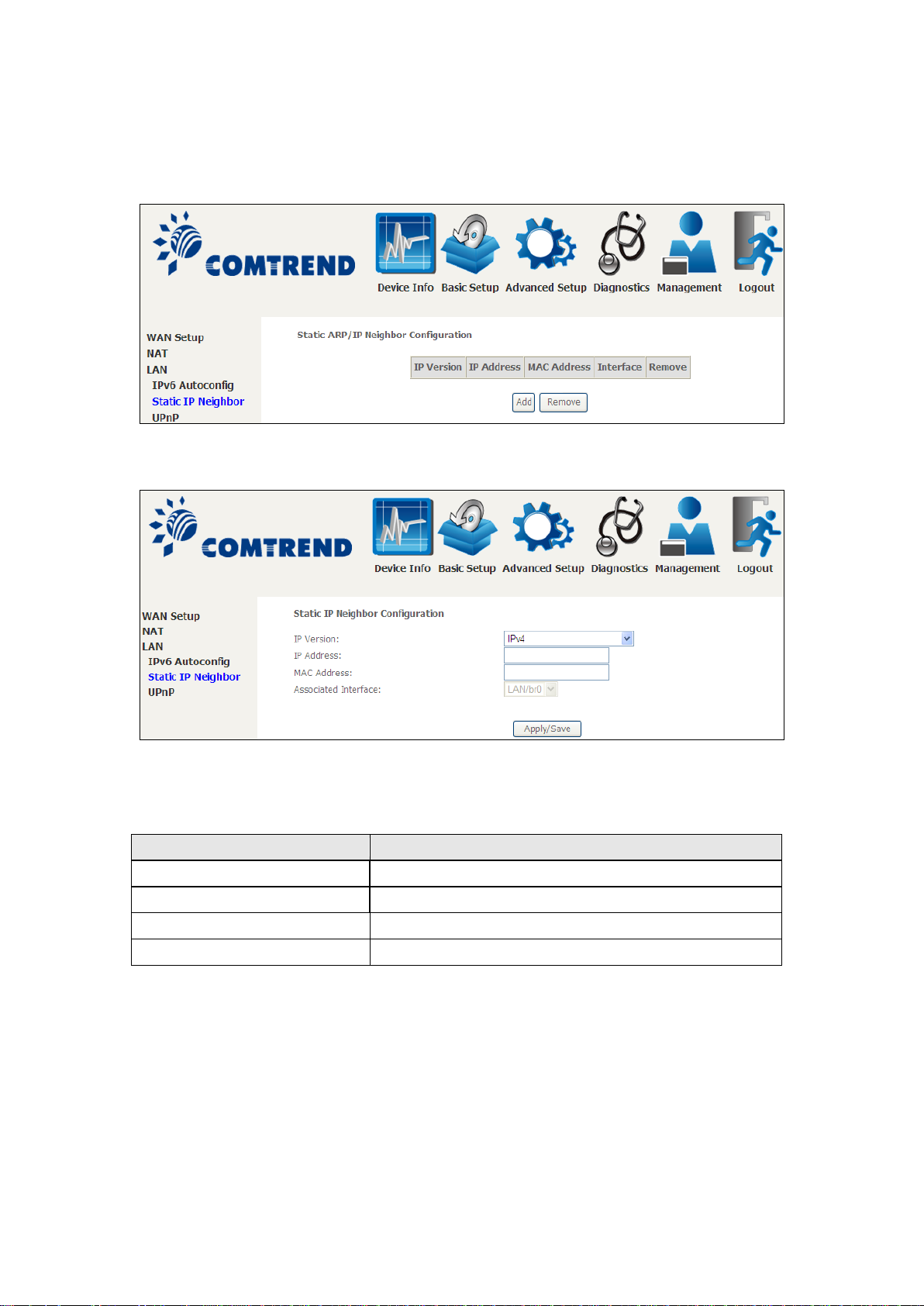
Click the Add button to display the following.
Click Apply/Save to apply and save the settings.
Page 59
58
5.3.3 UPnP
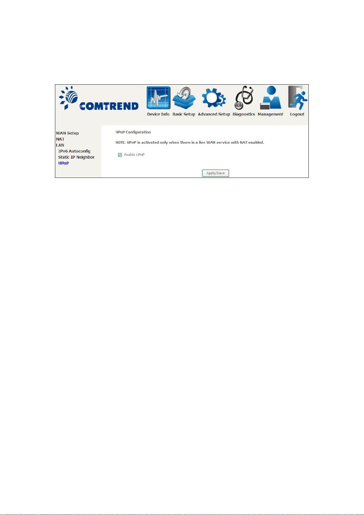
Select the checkbox provided and click Apply/Save to enable UPnP protocol.
Page 60
59
5.4 Wireless
Option
Description
Enable
Wireless
A checkbox that enables or disables the wireless LAN interface.
When selected, a set of basic wireless options will appear.
5.4.1 Basic
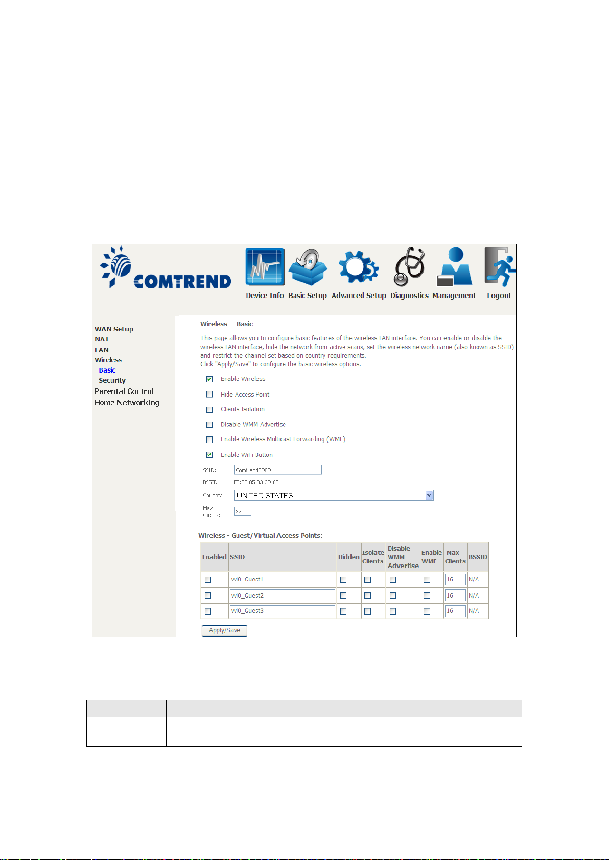
The Basic option allows you to configure basic features of the wireless LAN interface.
Among other things, you can enable or disable the wireless LAN interface, hide the
network from active scans, set the wireless network name (also known as SSID)
and restrict the channel set based on country requirements.
Click Apply/Save to apply the selected wireless options.
Consult the table below for descriptions of these options.
Page 61

60
Option
Description
Hide Access
Point
Select Hide Access Point to protect the access point from detection
configuration.
Clients
When enabled, it prev ents client PC s from seeing o ne another in My
wireless client communicating with another wireless client.
Disable WMM
Stops the router from ‘advertising’ its Wireless Multimedia (WMM)
time-sensitive applications (e.g. VoIP, Video).
Enable
Forwarding
Select the checkbox to enable this function.
Enable WiFi
Button
Select the checkbox to enable the WiFi button.
SSID
characters]
Sets the wireless network name. SSID stands for Service Set
granted access.
BSSID
The BSSID is a 48-bit identity used to identify a particular BS S
the BSSID is generated randomly.
Country
A drop-down menu that permits worldwide and specific national
US= worldwide, Japan=1-14, Jordan= 10-13, Israel= 1-13
Max Clients
The maximum number of clients that can access the router.
Wireless -
This router supports multiple SSIDs called Guest SSIDs or Virtual
column. To hide a Guest SSID select
NOTE: Remote wireless hosts cannot scan Guest SSIDs.
by wireless active scans. To check AP status in Windows XP, open
Network Connections from the start Menu and select View
Available Netwo rk Connections. If the access point is hidden, it
will not be listed there. To connect a client to a hidden access point,
the station must add the access point manually to its wireless
Isolation
Advertise
Wireless
Multicast
[1-32
Network Places or Network Neighborhood. Also, prevents one
functionality, which provides basic quality of service for
Identifier. All stations must be configured with the correct SSID to
access the WLAN. If the SSID does not match, that user will not be
(Basic Service Set) within an area. In Infrastructure BSS
networks, the BSSID is the MAC (Media Access Control) address of
the AP (Access Point); and in Independent BSS or ad hoc networks,
settings. Local regulations limit channel range :
Guest /
Virtual
Access Points
Access Points. To enable one or more Guest SSIDs select the
checkboxes in the Enabled
its checkbox in the Hidden column.
Do the same for Isolate Clients and Disable WMM Advertise.
For a description of these two functions, see the previous entries for
“Clients Isolation” and “Disable WMM Advertise”. Similarly, for
Enable WMF, Max Clients and BSSID, consult the matching
entries in this table.
Page 62
61
5.4.2 Security
Select SSID
Select the wireless network name from the drop-down box. SSID stands for Service
Set Identifier. All stations must be configured with the correct SSI D to access the
WLAN. If the SSID does not match, that client will not be granted access.
Network Authentication
wireless network. If network authentication is s et to Ope n, then n o authenticat ion
The following screen appears when Wireless Security is selected. The options shown
here allow you to configure security features of the wireless LAN interface.
Click Apply/Save to implement new configuration settings.
WIRELESS SECURITY
Setup requires that the user configure these settings using the Web User Interface
(see the table below).
This option specifies whether a network key is used for authentication to the
is provided. Despite this, the identity of the client is still verified.
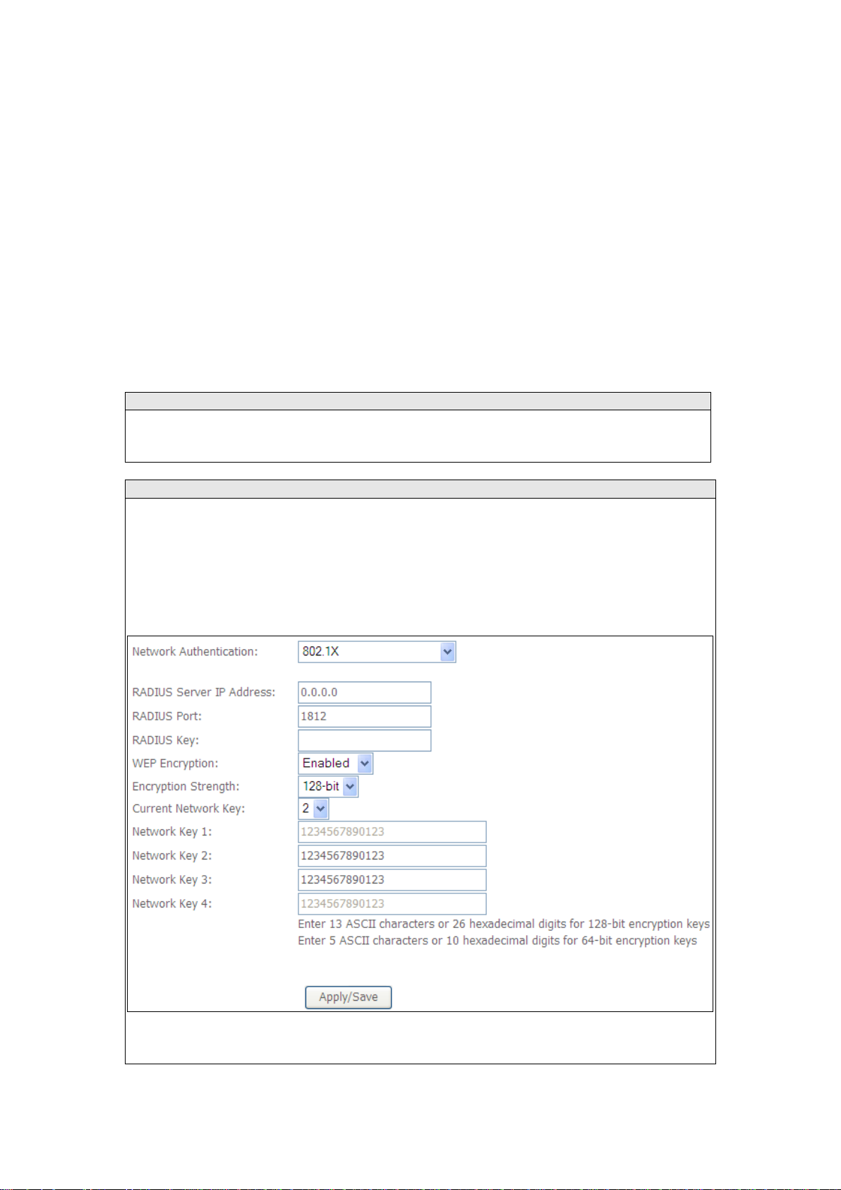
Each authentication type has its own settings. For example, selecting 802.1X
authentication will reveal the RADIUS Server IP address, Port and Key fields. WEP
Encryption will also be enabled as shown below.
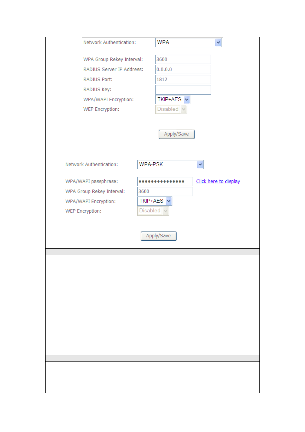
The settings for WPA authentication are show n below.
Page 63
62
WEP Encryption
This option specifies whether data sent over the network is encrypted. The same
ication. Four network
keys can be def ined although only one can be used at any one time. Use the Curre nt
Security options include auth enticat ion and e ncryption s ervice s based on the wired
tion keys are generated and
wireless network communications channel.
Encryption Strength
This drop-down list box will display when WEP Encryption is enabled. The key
64-bit or 128-bit. A 64-bit key is equivalent to 5 ASCII characters or 10
The settings for WPA-PSK authentication are shown next.
network key is us ed for data encryption and network authent
Network Key list bo x to select the appropriate network key.
equivalent privacy (WEP) algorithm. WEP is a set of security services used to
protect 802.11 networks from unauthorized access, such as eavesdropping; in this
case, the capture of wireless network traffic.
When data encryption is enabled, secret shared encryp
used by the source station and the destination station to alter frame bits, thus
avoiding disclosure to eavesdroppers.
Under shared key authentication, each wireless station is assumed to have received
a secret shared key over a secure channel that is independent from the 802.11
strength is proportional to the number of binary bits comprising the key. This
means that keys with a greater number of bits have a greater degree of security and
are considerably more difficult to crack. Encryption strength can be set to either
Page 64

63
hexadecimal numbers. A 128-bit key contains 13 ASCII characters or 26
hexadecimal numbers. Each key contains a 24-bit header (an initiation vector)
which enables parallel decoding of multiple streams of encrypted data.
Please see 6.13 for MAC Filter, Wireless Bridge and Advanced Wireless features.
 Loading...