

Page 1
6.9 IP Tunnel
6.9.1 IPv6inIPv4
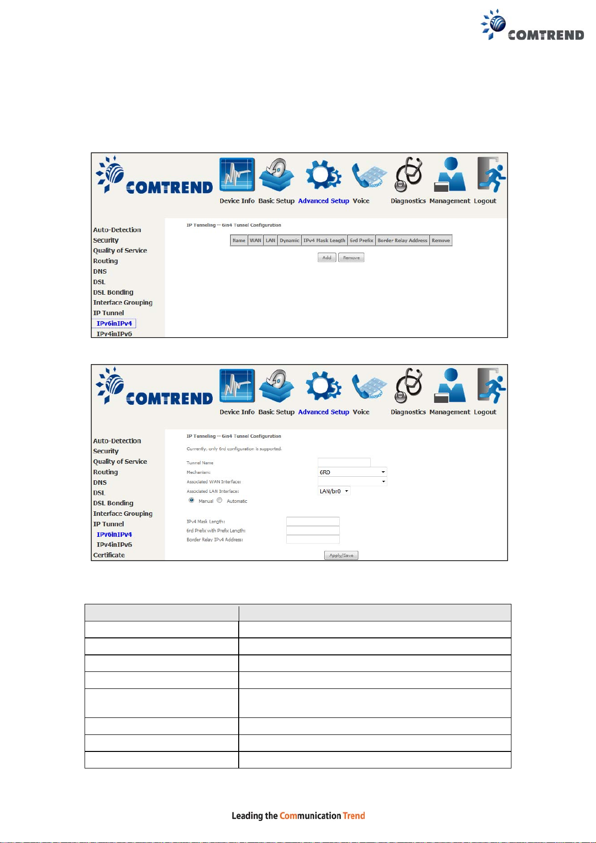
Configure 6in4 tunneling to encapsulate IPv6 traffic over explicitly-configured IPv4
links.
Click the Add button to display the following.
Click Apply/Save to apply and save the settings.
Options Description
Tunnel Name Input a name for the tunnel
Mechanism Mechanism used by the tunnel deployment
Associated WAN Interface Select the WAN interface to be used by the tunnel
Associated LAN Interface Select the LAN interface to be included in the tunnel
Manual/Automatic Select automatic for point-to-multipoint tunneling /
manual for point-to-point tunneling
IPv4 Mask Length The subnet mask length used for the IPv4 interface
6rd Prefix with Prefix Length Prefix and prefix length used fo r the IPv6 interface
Border Relay IPv4 Address Input the IPv4 address of the other device
103
Page 2
6.9.2 IPv4inIPv6
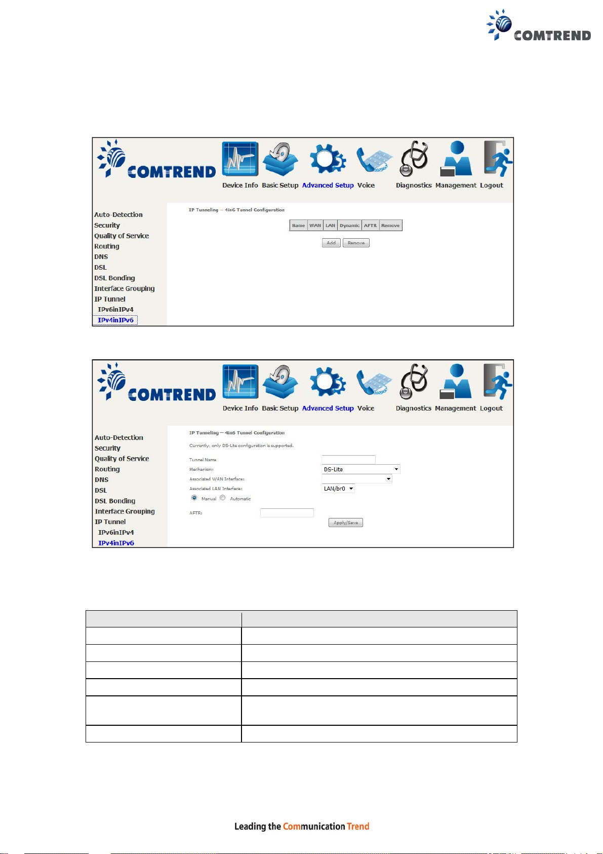
Configure 4in6 tunneling to encapsulate IPv4 traffic over an IPv6-onl y environment.
Click the Add button to display the following.
Click Apply/Save to apply and save the settings.
Options Description
Tunnel Name Input a name for the tunnel
Mechanism Mechanism used by the tunnel deployment
Associated WAN Interface Select the WAN interface to be used by the tunnel
Associated LAN Interface Select the LAN interface to be included in the tunnel
Manual/Automatic Select automatic for point-to-multipoint tunneling /
manual for point-to-point tunneling
AFTR Address of Address Family Translation Router
104
Page 3
6.10 Certificate
A certificate is a public key, attached with its owner’s information (company name,
server name, personal real name, contact e-mail, postal address, etc) and digital
signatures. There will be one or more digital signatures attached to the certificate,
indicating that these entities have verified that this certificate is valid.
6.10.1 Local
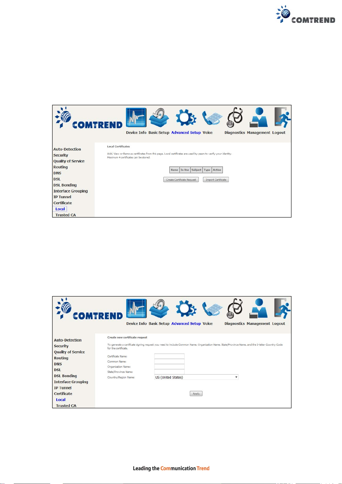
CREATE CERTIFICATE REQUEST
Click Create Certificate Request to generate a certificate-signing request.
The certificate-signing request can be submitted to the vendor/ISP/ITSP to apply for
a certificate. Some information must be included in the certificate-signing request.
Your vendor/ISP/ITSP will ask you to provide the information they require and to
provide the information in the format they regulate. Enter the required information
and click Apply to generate a private key and a certificate-signing request.
The following table is provided for your reference.
105
Page 4
Field Description
Certificate Name A user-defined name for the certificate.
Common Name Usually , the fully qualified domain name for the machine.
Organization Name The exact legal name of your organization.
Do not abbreviate.
State/Province Name The state or province where your organization is located.
It cannot be abbreviated.
Country/Region Name The two-letter ISO abbreviation for your country.
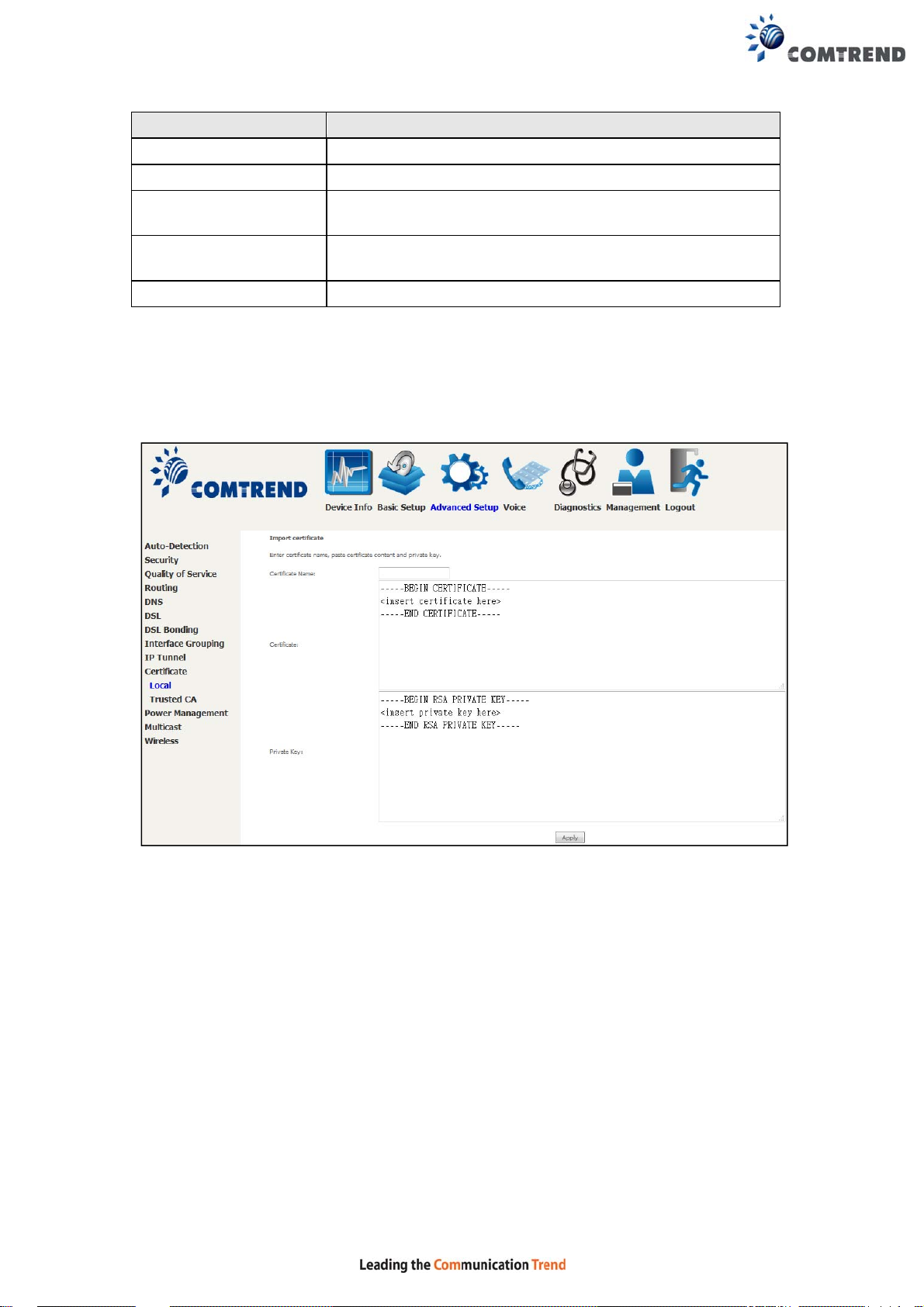
IMPORT CERTIFICATE
Click Import Certificate to paste the certificate content and the private key
provided by your vendor/ISP/ITSP into the corresponding boxes shown below.
Enter a certificate name and click the Apply button to import the certificate and its
private key.
106
Page 5
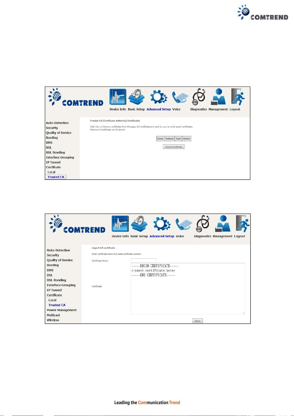
6.10.2 Trusted CA
CA is an abbreviation for Certificate Authority, which is a part of the X.509 system.
It is itself a certificate, attached with the owner inf o rmation of this certificate
authority; but its purpose is not encryption/decryption. Its purpose is to sign and
issue certificates, in order to prove that these certificates are valid.
Click Import Certificate to paste the certificate content of your trusted CA. The
CA certificate content will be provided by your vendor/ISP /ITSP and is used to
authenticate the Auto-Configuration Server (ACS) that the CPE will connect to.
Enter a certificate name and click Apply to import the CA certificate.
107
Page 6
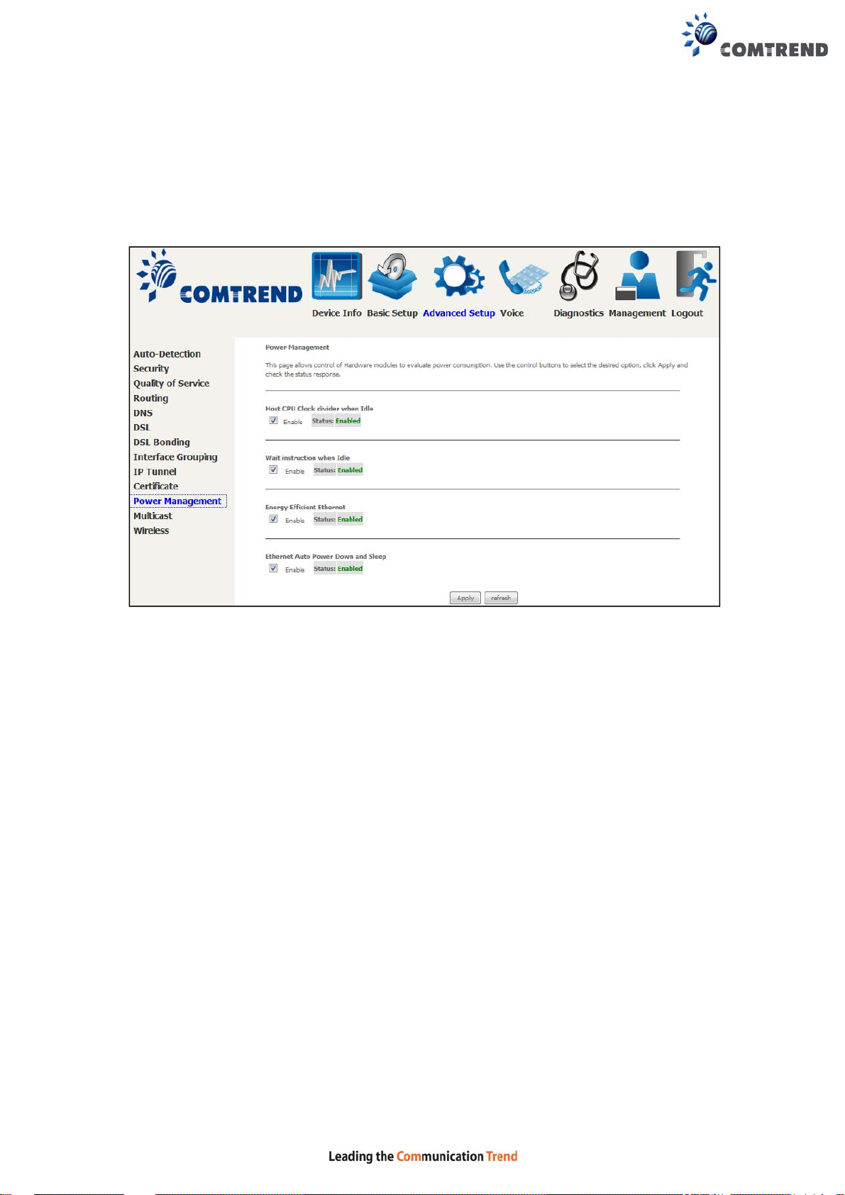
6.11 Power Management
This screen allows for control of hardware modules to evaluate power consumpti on.
Use the buttons to select the desired option, click Apply and check the response.
108
Page 7
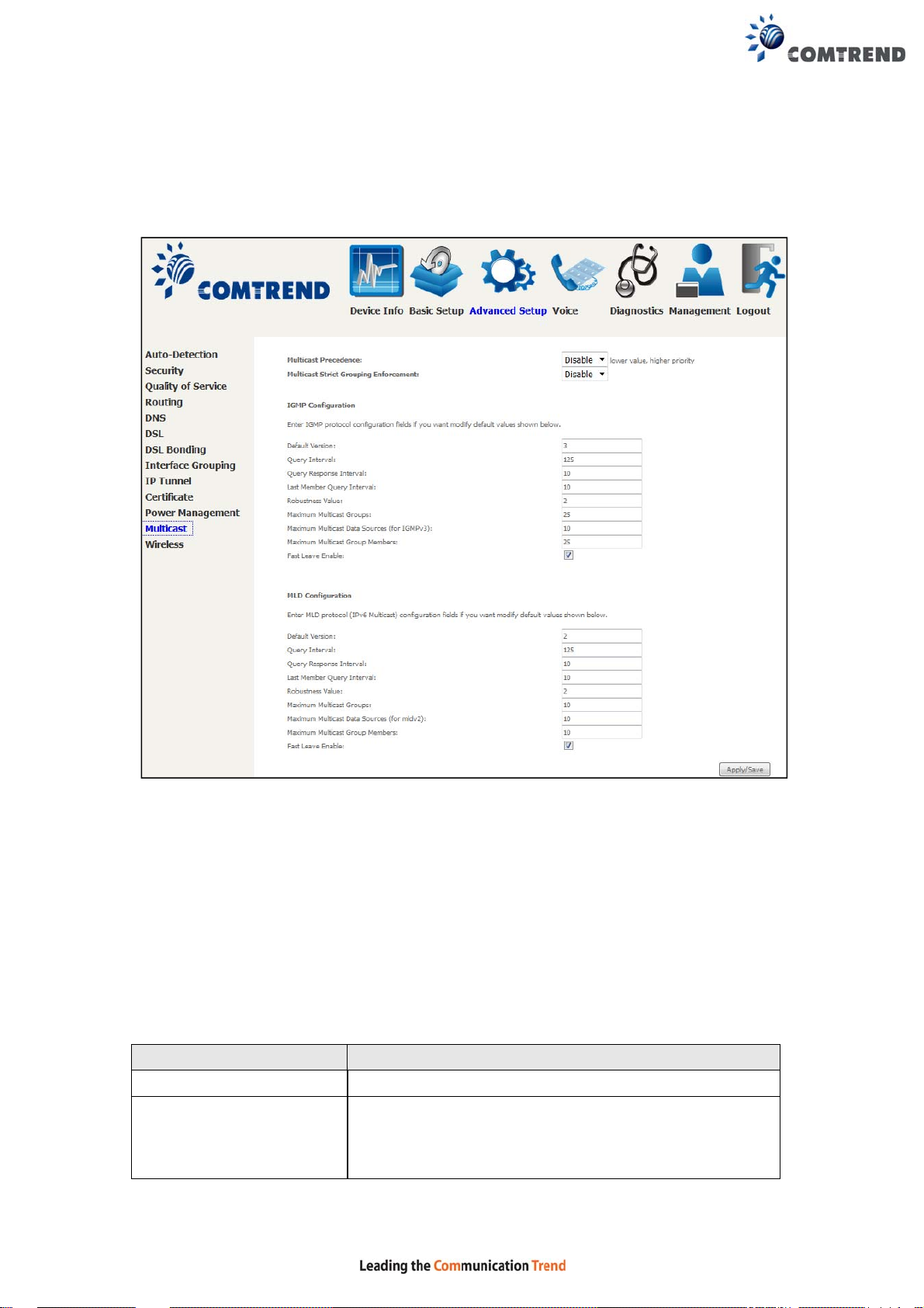
6.12 Multicast
Input new IGMP or MLD protocol configuration fields if you want modify default
values shown. Then click Apply/Save.
Multicast Precedence:
Select precedence of multicast packets.
Multicast Strict Grouping Enforcement:
Enable/Disable multicast strict grouping.
Field Description
Default Version Define IGMP using version with video server.
Query Interval The query interval is the amount of time in seconds
between IGMP General Query messages sent by the
router (if the router is the querier on this subnet). The
default query interval is 125 seconds.
109
Page 8

Field Description
Query Response Interval The query response interval is the maximum amount
of time in seconds that the IGMP router waits to
receive a response to a General Query message. The
query response interval is the Maximum Response
Time field in the IGMP v2 Host Membership Query
message header. The default query response interval
is 10 seconds and must be less than the query
interval.
Last Member Query
Interval
The last member query interval is the amount of time
in seconds that the IGMP router waits to receive a
response to a Group-Specific Query message. The last
member query interval is also the amount of time in
seconds between successive Group-Specific Query
messages. The default last member query interval is
10 seconds.
Robustness Value The robustness variable is a way of indicating how
susceptible the subnet is to lost packets. IGMP can
recover from robustness variable minus 1 lost IGMP
packets. The robustness variable should be set to a
value of 2 or greater. The default robustness variable
value is 2.
Maximum Multicast
Setting the maximum number of Multicast groups.
Groups
Maximum Multicast Data
Define the maximum multicast video stream number.
Sources (for IGMPv3)
Maximum Multicast
Group Members
Setting the maximum number of groups that ports
can accept.
Fast Leave Enable When you enable IGMP fast-leave processing, the
switch immediately removes a port when it detects an
IGMP version 2 leave message on that port.
110
Page 9
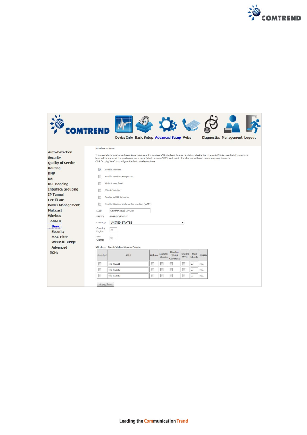
6.13 Wireless
6.13.1 Basic 2.4GHz
The Basic option allows you to configure basic features of the wireless LAN interface.
Among other things, you can enable or disable the wireless LAN interface, hide the
network from active scans, set the wireless network name (also known as SSID)
and restrict the channel set based on country requirements.
Click Apply/Save to configure the basic wireless options.
Consult the table below for descriptions of these options.
111
Page 10

Option Description
Enable
Wireless
Enable
Wireless
Hotspot2.0
Hide Access
Point
A checkbox that enables or disables the wireless LAN interface.
When selected, a set of basic wireless options will appear.
Enable Wireless Hotspot 2.0 (Wi-Fi Certified Passpoint) on the
wireless interface.
Select Hide Access Point to protect the access point from detection by
wireless active scans. To check AP status in Windows XP, open
Network Connections from the start Menu and select View
Available Network Connections. If the access point is hidden, it
will not be listed there. To connect a client to a hidden access point,
the station must add the access point manually to its wireless
configuration.
Clients
Isolation
When enabled, it prevents client PCs from seeing one another in My
Network Places or Network Neighborhood. Also, prevents one
wireless client communicating with another wireless client.
Disable
WMM
Advertise
Enable
Stops the router from ‘advertising’ its Wireless Multimedia (WMM)
functionality , which provides basic quality of service for time-sensitive
applications (e.g. VoIP, Video).
Select the checkbox to enable this function.
Wireless
Multicast
Forwarding
SSID
[1-32
characters]
Sets the wireless network name. SSID stands for Service Set
Identifier. All stations must be configured with the correct SSID to
access the WLAN. If the SSID does not match, that user will not be
granted access.
BSSID The BSSID is a 48-bit identity used to identify a particular BSS (Basic
Service Set) within an area. In Infrastructure BSS networks, the
BSSID is the MAC (Media Access Control) address of the AP (Access
Point); and in Independent BSS or ad hoc networks, the BSSID is
generated randomly.
Country A drop-down menu that permits worldwide and specific national
settings. Local regulations limit channel range:
US= worldwide, Japan=1-14, Jordan= 10-13, Israel= 1-13
Country
Wireless country code for transmit power limit.
RegRev
Max Clients The maximum number of clients that can access the router.
Wireless -
Guest /
Virtual
Access
Points
This router supports multiple SSIDs called Guest SSIDs or Virtual
Access Points. To enable one or more Guest SSIDs select the
checkboxes in the Enabled column. T o hide a Guest SSID select its
checkbox in the Hidden column.
Do the same for Isolate Clients and Disable WMM Advertise. For
a description of these two functions, see the previous entries for
“Clients Isolation” and “Disable WMM Advertise”. Similarly , for Enable
WMF, Max Clients and BSSID, consult the matching entries in this
table.
NOTE: Remote wireless hosts cannot scan Guest SSIDs.
112
Page 11
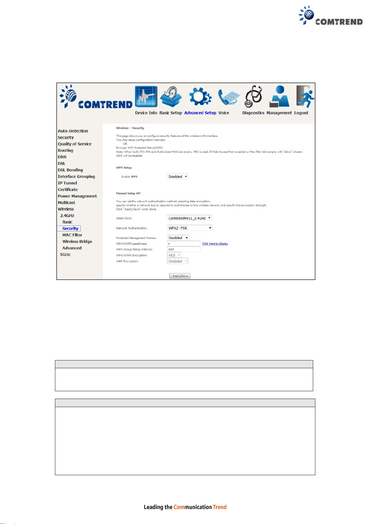
6.13.2 Security 2.4GHz
The following screen appears when Wireless Security is selected. The options shown
here allow you to configure security features of the wireless LAN interface.
Please see 6.13.3 for WPS setup instructions.
Click Apply/Save to implement new configuration settings.
WIRELESS SECURITY
Setup requires that the user configure these settings using the Web User Interface
(see the table below).
Select SSID
Select the wireless network name from the drop-down menu. SSID stands for
Service Set Identifier. All stations must be configured with the correct SSID to
access the WLAN. If the SSID does not match, that client will not be gr anted access.
Network Authentication
This option specifies whether a network key is used for authenticat ion to the
wireless network. If network authe ntication is set to Open, then no authenti cation
is provided. Despite this, the iden tity of the client is still verified.
Each authentication type has its own settings. For example, selecting 802.1X
authentication will reveal the RADIUS Server IP address, Port and Key fields. WEP
Encryption will also be enabled as shown below.
Different authentication type pops up different settings requests.
113
Page 12
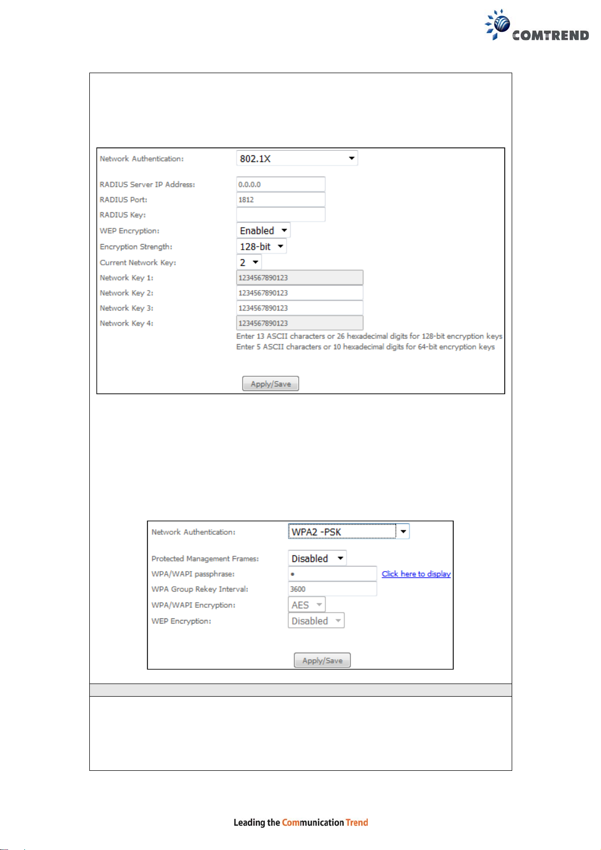
Choosing 802.1X, enter RADIUS Server IP address, RADIUS P ort, RADIUS key and
Current Network Key.
Also, enable WEP Encryption and select Encryption Strength.
Select the Current Network Key and enter 13 ASCII characters or 26 hexadecimal
digits for 128-bit encryption keys and enter 5 ASCII characters or 10 hexadecimal
digits for 64-bit encryption keys.
Choosing WPA2-PSK, you must enter WPA Pre-Shared Key and Group Rekey
Interval.
WEP Encryption
This option specifies whether data sent over the network is encrypted. The same
network key is used for data encryption and network authentication. Four network
keys can be defined although only one can be used at any one time. Use the Current
Network Key list box to select the appropriate network key.
114
Page 13

Security options include authentication and encryption services based on the wire d
equivalent privacy (WEP) algorithm. WEP is a set of security services used to
protect 802.11 networks from unauthorized access, such as eavesdropping; in this
case, the capture of wireless network traffic.
When data encryption is enabled, secret shared encryption keys are generated and
used by the source station and the destination station to alter frame bits, thus
avoiding disclosure to eavesdroppers.
Under shared key authentication, each wire less station is assumed to have received
a secret shared key over a secure channel that is independent from the 802.11
wireless network communications channel.
Encryption Strength
This drop-down list box will display when WEP Encryption is en abled. The key
strength is proportional to the number of binary bits comprising the key. This
means that keys with a greater number of bits have a grea ter degree of security and
are considerably more difficult to crack. Encryption strength can be set to either
64-bit or 128-bit. A 64-bit key is equivalent to 5 ASCII characters or 10
hexadecimal numbers. A 128-bit key contains 13 ASCII characters or 26
hexadecimal numbers. Each key contains a 24-bit header (an initiation vector)
which enables parallel decoding of multiple streams of encrypted data.
115
Page 14
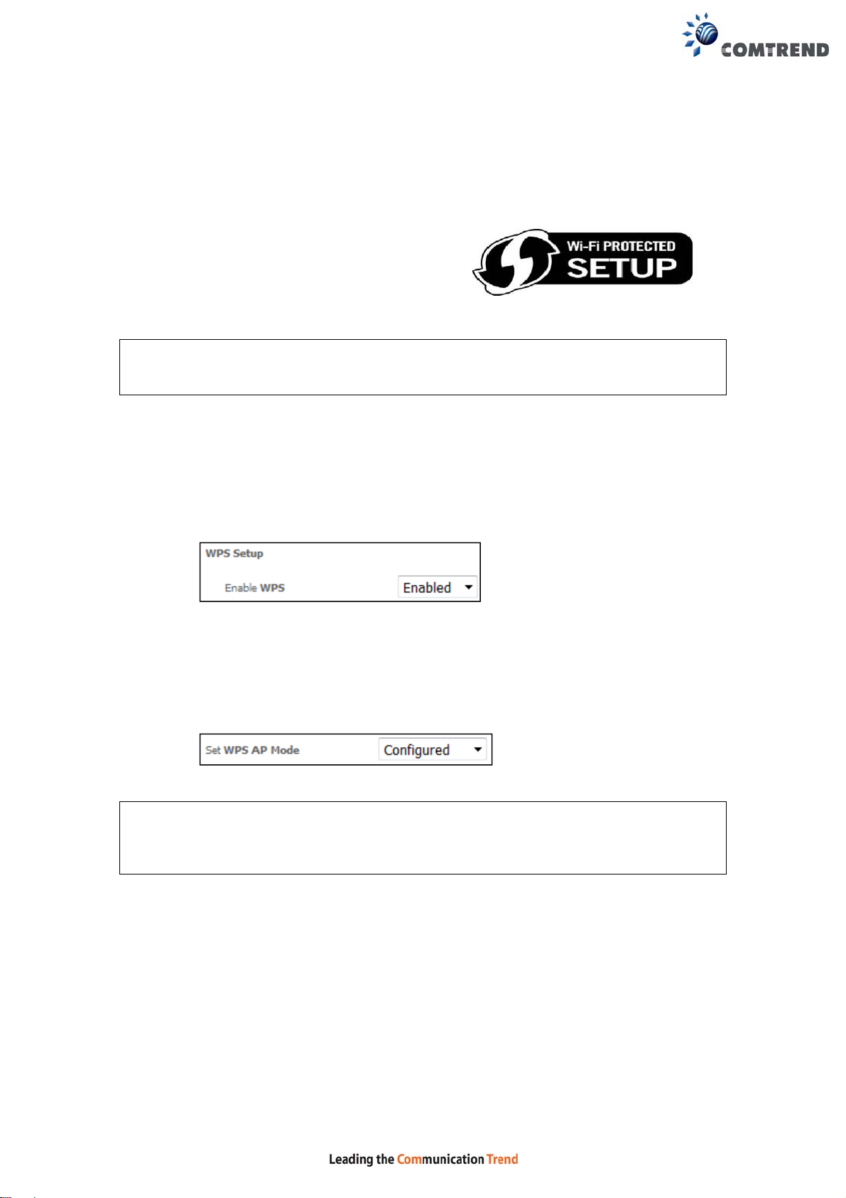
6.13.3 WPS 2.4GHz
Wi-Fi Protected Setup (WPS) is an industry standard that simplifies wireless security
setup for certified network devices. Every WPS certified device has both a PIN
number and a push button, located on the device or accessed through device
software. The NexusLink 3240 has a WPS button on the device.
Devices with the WPS logo (shown here)
support WPS. If the WPS logo is not present
on your device it still may support WPS, in
this case, check the device documentation
for the phrase “Wi-Fi Protected Setup”.
NOTE: WPS is only available in Open, WPA-PSK, WPA2-PSK and Mixed
WPA2/WPA-PSK network authentication modes. Other authentication
modes do not use WPS so they must be configured manually.
To configure security settings with WPS, follow the procedures below .
I. Setup
Step 1: Enable WPS by selecting Enabled from the drop down list box shown.
Step 2: Set the WPS AP Mode. Configured is used when the NexusLink 3240 will
assign security settings to clients. Unconfigured is used when an
external client assigns security settings to the NexusLink 3240.
NOTES: Your client may or may not have the ability to provide security settings to
the NexusLink 3240. If it does not, then you must set the WPS AP mode
to Configured. Consult the device documentation to check its capabilities.
116
Page 15
IIa. PUSH-BUTTON CONFIGURATION
The WPS push-button configuration provides a semi-automated configuration
method. The WPS button on the front panel of the router can be used for this
purpose.
The WPS push-button configuration is described in the procedure below. It is
assumed that the Wireless function is Enabled and that the router is configured as
the Wireless Access Point (AP) of your WLAN. In addition, the wireless client must
also be configured correctly and turned on, with WPS function enabled.
NOTE: The wireless AP on the router searches for 2 minutes. If the router stops
searching before you complete Step 4, return to Step 3.
Step 3: Press WPS button
Press the WPS button on the front panel of the router. The WPS LED will
blink to show that the router has begun searching for the client.
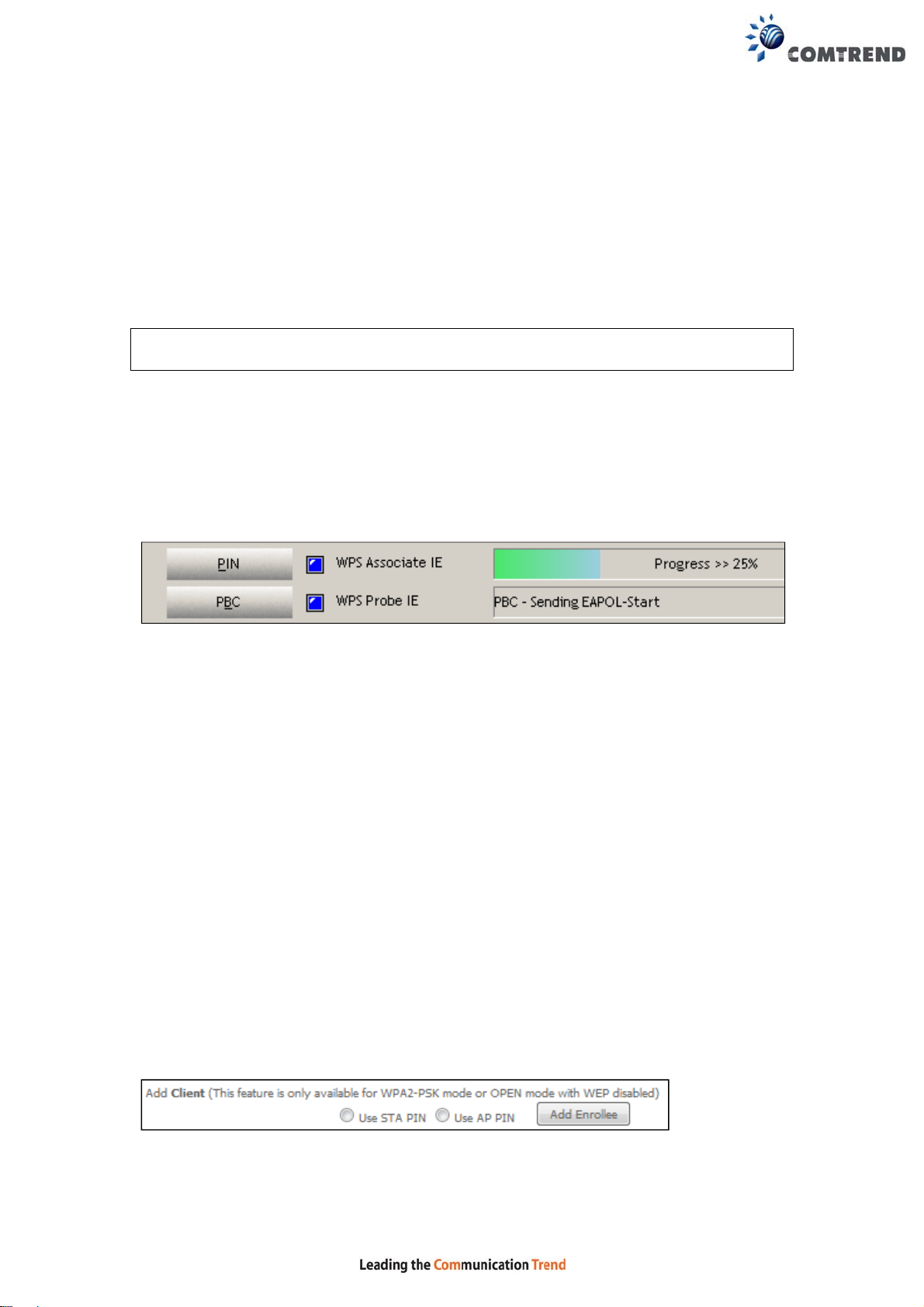
Step 4: Go to your WPS wireless client and activate the push-button function.
A typical WPS client screenshot is shown below as an example.
Now go to Step 7 (part III. Check Connection) to check the WPS connection.
IIb. WPS – PIN CONFIGURATION
Using this method, security settings are configured with a personal identification
number (PIN). The PIN can be found on the device itself or within the software.
The PIN may be generated randomly in the latter case. To obtain a PIN number for
your client, check the device documentation for specific instructions.
The WPS PIN configuration is described in the procedure below. It is assumed that
the Wireless function is Enabled and that the router is conf igured as the Wireless
Access Point (AP) of your wireless LAN. In addition, the wireless client must also be
configured correctly and turned on, with WPS function enabled.
Step 5: Select the PIN radio button in the WSC Setup section of the Wireless
Security screen, as shown in A or B below , and then click the appropriate
button based on the WSC AP mode selected in step 2.
A - For Configured mode, click the Add Enrollee button.
117
Page 16
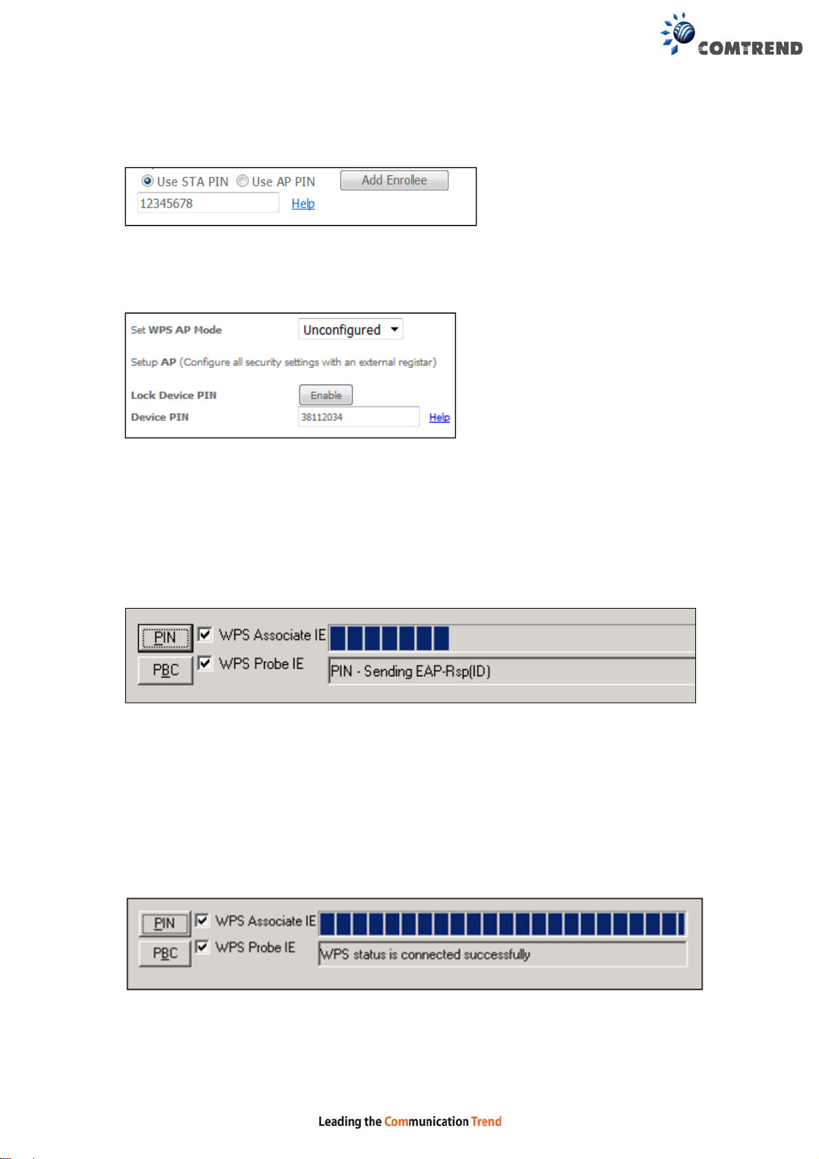
Enter STA PIN: a Personal Identification N umber (PIN) has to be read from either
a sticker or the display on the new wireless device. This PIN must then be inputted
at representing the network, usually the Access Point of the network.
B - For Unconfigured mode, click the Config AP button.
Step 6: Activate the PIN functio n on the wi reless client. For Configured mode,
the client must be configured as an Enrollee. For Unconfigured mode,
the client must be configured as the Registr ar. This is different from the
External Registrar function provided in Windows Vista.
The figure below provides an example of a WPS client PIN function in-progress.
III. CHECK CONNECTION
Step 7: If the WPS setup method was successful, you will be able access the
wireless AP from the client. The client software should show the status.
The example below shows that the connection established successfully.
You can also double-click the Wirele ss Network Connection icon from the
Network Connections window (or the system tr ay) to confirm the status of
the new connection.
118
Page 17
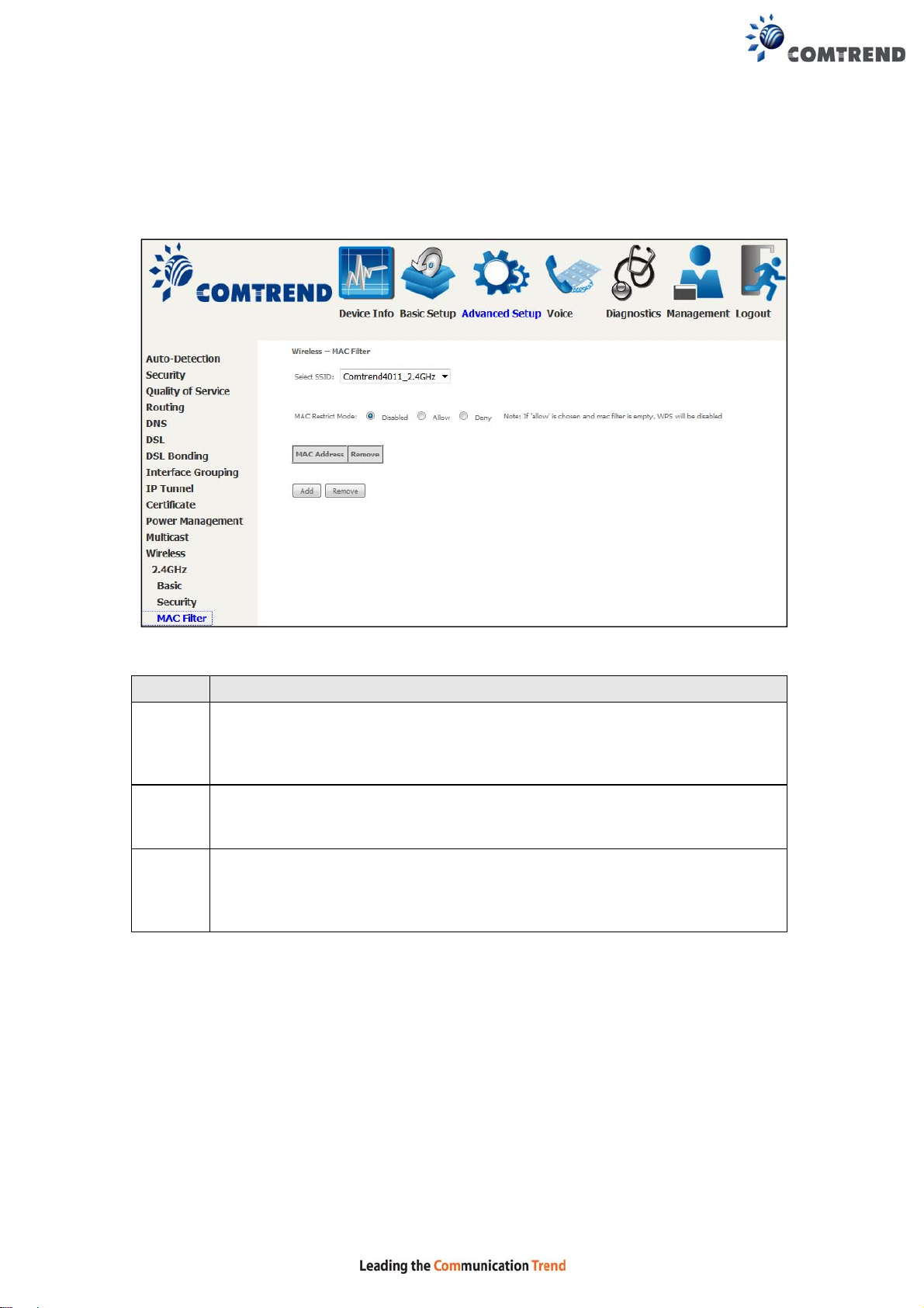
6.13.4 MAC Filter 2.4GHz
This option allows access to the router to be restricted based upon MAC addresses.
To add a MAC Address filter, click the Add button shown below. To delete a filter,
select it from the MAC Address table below and click the Remove button.
Option Description
Select
SSID
MAC
Restrict
Mode
MAC
Address
After clicking the Add button, the following screen appears.
Select the wireless network name from the drop-down menu. SSID
stands for Service Set Identifier. All stations must be configured with the
correct SSID to access the WLAN. If the SSID does not mat ch, that user
will not be granted access.
Disabled: MAC filtering is disabled.
Allow: Permits access for the specified MAC addresses.
Deny: Rejects access for the specified MAC addresses.
Lists the MAC addresses subject to the MAC Restrict Mode. A maximum
of 60 MAC addresses can be added. Every network device has a unique
48-bit MAC address. This is usually shown as xx.xx.xx. xx.xx.xx, where
xx are hexadecimal numbers.
119
Page 18
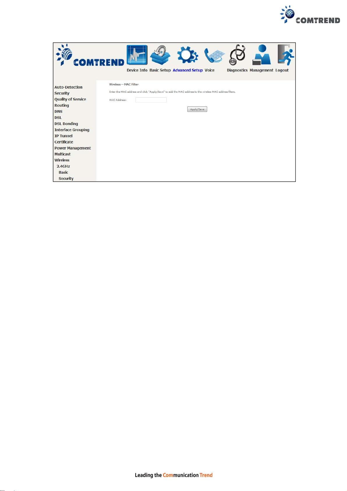
Enter the MAC address in the box provided and click Apply/Save.
120
Page 19
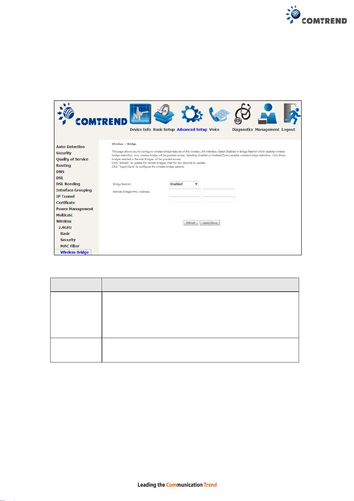
6.13.5 Wireless Bridge 2.4GHz
This screen allows for the configuration of wireless bridge features of the WiFi
interface. See the table below for detailed explanations of the various options.
Click Apply/Save to implement new configuration settings.
Feature Description
Bridge Restrict Selecting Disabled disables wireless bridge restriction, which
means that any wireless bridge will be granted access.
Selecting Enabled or Enabled (Scan) enables wireless bridge
restriction. Only those bridges selected in the Remote Bridges
list will be granted access. Click Refresh to update the station
list when Bridge Restrict is enabled.
Remote
Bridges MAC
Address
Enter the list of MAC addresses allowed to act as wireless bridge
clients.
121
Page 20
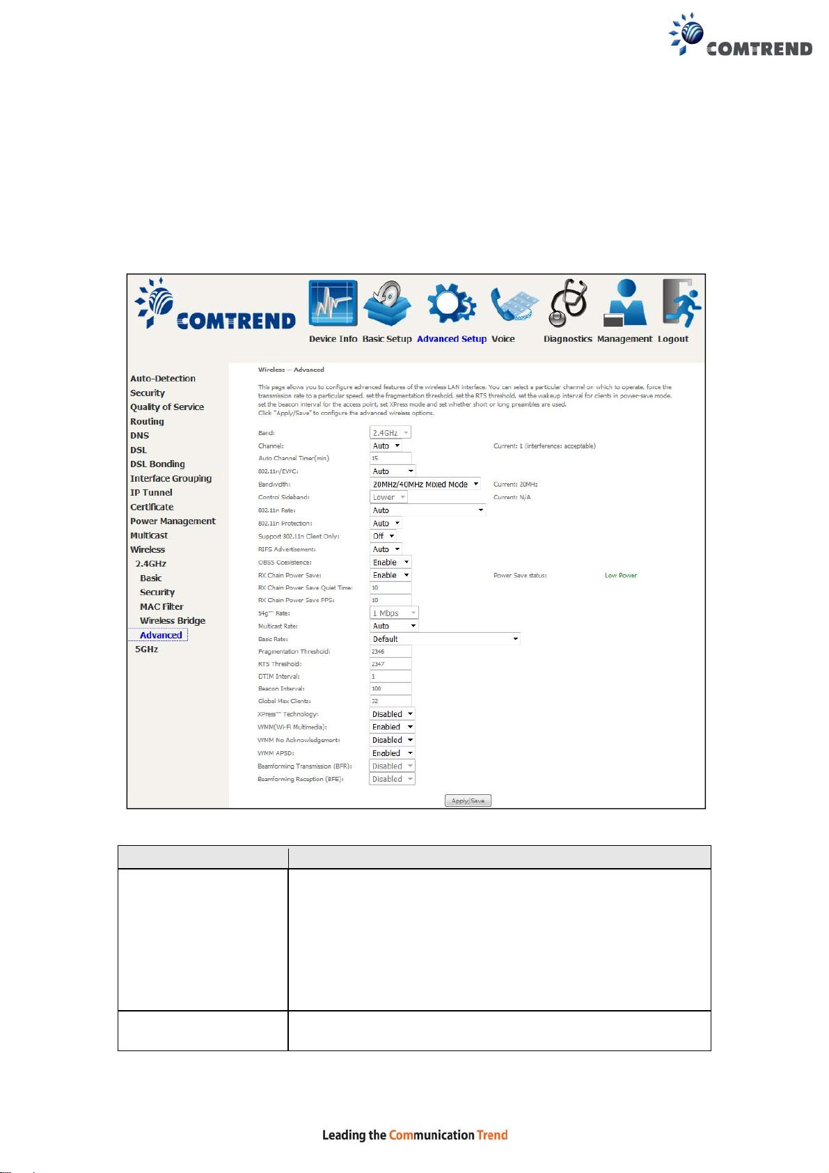
6.13.6 Advanced 2.4GHz
The Advanced screen allows you to configure advanced features o f the wireless LAN
interface. You can select a particular channel on which to operate, force the
transmission rate to a particular speed, set the fragmentation threshold, set the RTS
threshold, set the wakeup interval for clients in power-save mode, set the beacon
interval for the access point, set XPress mode and set whether short or long
preambles are used. Click Apply/Save to set new advanced wireless options.
Field Description
Band Set to 2.4 GHz for compatibility with IEEE 802.11x
standards. The new amendment allows IEEE 802.11n units
to fall back to slower speeds so that legacy IEEE 802.11x
devices can coexist in the same network. IEEE 802.11g
creates data-rate parity at 2.4 GHz with the IEEE 802.11a
standard, which has a 54 Mbps rate at 5 GHz. (IEEE
802.11a has other differences compared to IEEE 802.11b
or g, such as offering more channels.)
Channel Drop-down menu that allows selection of a specific
channel.
122
Page 21

Field Description
Auto Channel Timer
Auto channel scan timer in minutes (0 to disable)
(min)
802.11n/EWC An equipment interoperability standard setting based on
IEEE 802.11n Draft 2.0 and En hanced Wireless Consortium
(EWC)
Bandwidth Select 20MHz or 40MHz bandwidth. 40MHz bandwidth uses
two adjacent 20MHz bands for increased data throughput.
Control Sideband Select Upper or Lower sideband when in 40MHz mode.
802.11n Rate Set the physical transmission rate (PHY).
802.11n Protection Turn Off for maximized throughput.
Turn On for greater security.
Support 802.11n
Client Only
Turn Off to allow 802.11b/g clients access to the router.
T ur n On to prohibit 802.11b/g client’s access to the ro uter.
RIFS Advertisement One of several draft-n features designed to improve
efficiency. Provides a shorter delay between OFDM
transmissions than in802.11a or g.
OBSS Co-Existence Co-existence between 20 MHZ AND 40 MHZ overlapping
Basic Service Set (OBSS) in WLAN.
RX Chain Power Save Enabling this feature turns off one of the Receive chains,
going from 2x2 to 2x1 to save power.
RX Chain Power Save
Quiet Time
The number of seconds the traffic must be below the PPS
value below before the Rx Chain Power Save feature
activates itself.
RX Chain Power Save
PPS
The maximum number of packets per seconds that can be
processed by the WLAN interface for a duration of Quiet
Time, described above, before the Rx Chain Power Sa v e
feature activates itself.
54g Rate Drop-down menu that specifies the following fixed rates:
Auto: Default. Uses the 11 Mbps data rate when possible
but drops to lower rates when necessary. 1 Mbps, 2Mbps,
5.5Mbps, or 11Mbps fixed rates. The appropriate setting
is dependent on signal strength.
Multicast Rate Setting for multicast packet transmit rate (1-54 Mbps)
Basic Rate Setting for basic transmission rate.
Fragmentation
Threshold
A threshold, specified in bytes, that determines whether
packets will be fragmented and at what size. On an
802.11 WLAN, packets that exceed the fragmentation
threshold are fragmented, i.e., split into, smaller units
suitable for the circuit size. Packets smaller than the
specified fragmentation threshold value are not
fragmented. Enter a value between 256 and 2346. If you
experience a high packet error rate, try to slightly increase
your Fragmentation Threshold. The value should remain
at its default setting of 2346. Setting the Fragmentation
Threshold too low may result in poor performance.
123
Page 22

Field Description
RTS Threshold Request to Send, when set in bytes, specifies the packet
size beyond which the WLAN Card invokes its RTS/CTS
mechanism. Packets that exceed the specified RTS
threshold trigger the RTS/CTS mechanism. The NIC
transmits smaller packet without using RTS/CTS. The
default setting of 2347 (maximum length) disables RTS
Threshold.
DTIM Interval Delivery T raffic Indication Message (DTIM) is also known as
Beacon Rate. The entry range is a value between 1 and
65535. A DTIM is a countdown variable that informs clients
of the next window for listening to broadcast and multicast
messages. When the AP has buffered broadcast or
multicast messages for associated clients, it sends the next
DTIM with a DTIM Interval value. AP Clients hear the
beacons and awaken to receive the broadcast and
multicast messages. The default is 1.
Beacon Interval The amount of time between beacon transmissions in
milliseconds. The default is 100 ms and the acceptable
range is 1 – 65535. The beacon transmissions identify the
presence of an access point. By default, network devices
passively scan all RF channels listening for beacons coming
from access points. Before a station enters power save
mode, the station needs the beacon interval to know when
to wake up to receive the beacon (and learn whether there
are buffered frames at the access point).
Global Max Clients The maximum number of clients that can connect to the
router.
Xpress
TM
Technology Xpress Technology is compliant with draft specifications of
two planned wireless industry standards.
WMM (Wi-Fi
Multimedia)
The technology maintains the priority of audio, video and
voice applications in a Wi-Fi network. It allows multimedia
service get higher priority.
WMM No
Acknowledgement
Refers to the acknowledge policy used at the MAC level.
Enabling no Acknowledgement can result in more efficient
throughput but higher error rates in a noisy Radio
Frequency (RF) environment.
WMM APSD This is Automatic Power Save Delivery. It saves power.
Beamforming
Transmission (BFR)
Beamforming
Reception (BFE)
Enable beamforming signal enhance for wireless
transmission.
Enable beamforming signal enhance for wireless reception.
124
Page 23
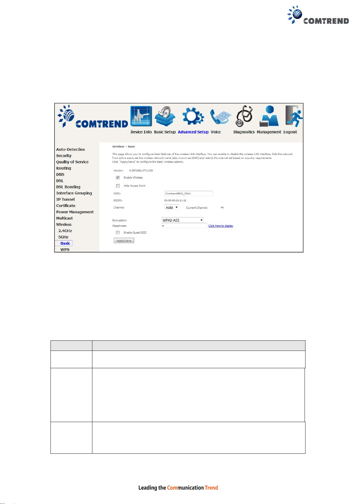
6.13.7 Basic 5GHz
The Basic option allows you to configure basic features of the wireless LAN interface.
Among other things, you can enable or disable the wireless LAN interface, hide the
network from active scans, set the wireless network name (also known as SSID)
and restrict the channel set based on country requirements.
Click Apply/Save to configure the basic wireless options.
Consult the table below for descriptions of these options.
Option Description
Enable
Wireless
Hide Access
Point
SSID
[1-32
characters]
A checkbox that enables or disables the wireless LAN interface.
When selected, a set of basic wireless options will appear.
Select Hide Access Point to protect the access point from detection by
wireless active scans. To check AP status in Windows XP, open
Network Connections from the start Menu and select View
Available Network Connections. If the access point is hidden, it
will not be listed there. To connect a client to a hidden access point,
the station must add the access point manually to its wireless
configuration.
Sets the wireless network name. SSID stands for Service Set
Identifier. All stations must be configured with the correct SSID to
access the WLAN. If the SSID does not match, that user will not be
granted access.
125
Page 24
Option Description
BSSID The BSSID is a 48-bit identity used to identify a particular BS S (Basic
Service Set) within an area. In Infrastructure BSS networks, the
BSSID is the MAC (Media Access Control) address of the AP (Access
Point); and in Independent BSS or ad hoc networks, the BSSID is
generated randomly.
Channel Drop-down menu that allows selection of a specific channel.
Encryption The encryption mode used for the wireless LAN interface.
Passphrase Enter a passphrase of at least 8 digits is required for WP A2 mode and
mixed mode wireless encryption.
Enable
Guest SSID
Click Enable Guest SSID to enable an additional SSID to provide
varied access.
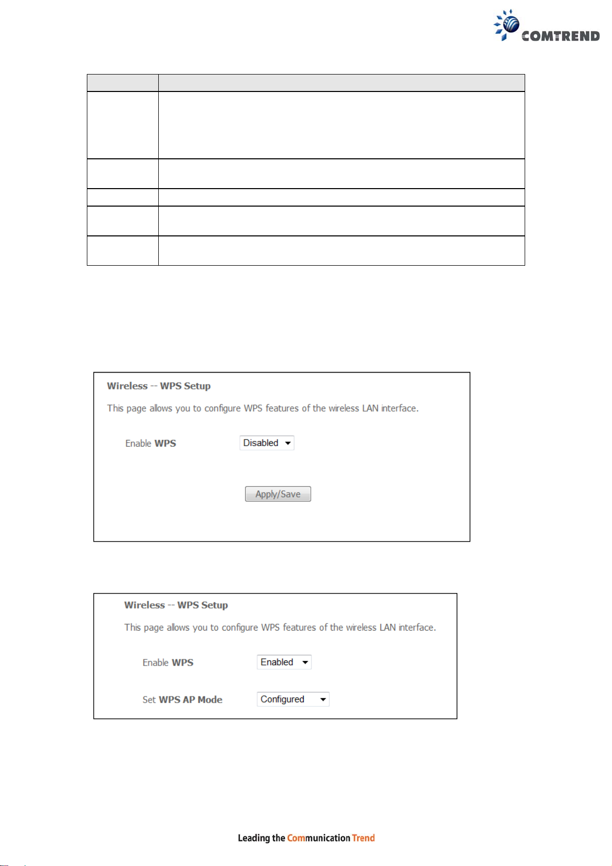
6.13.8 WPS 5GHz
Refer to 6.13.3 for WPS setup procedure.
WPS can be disabled / enabled by selecting the corresponding option and click
“Apply/Save”
a. When enabled in configured mode, use Push button or PIN to allow client
connection.
To activate Push button, click on the “Add Enrollee PBC” button or use the 5G Wifi
On/Off & WPS button on the front panel.
126
Page 25
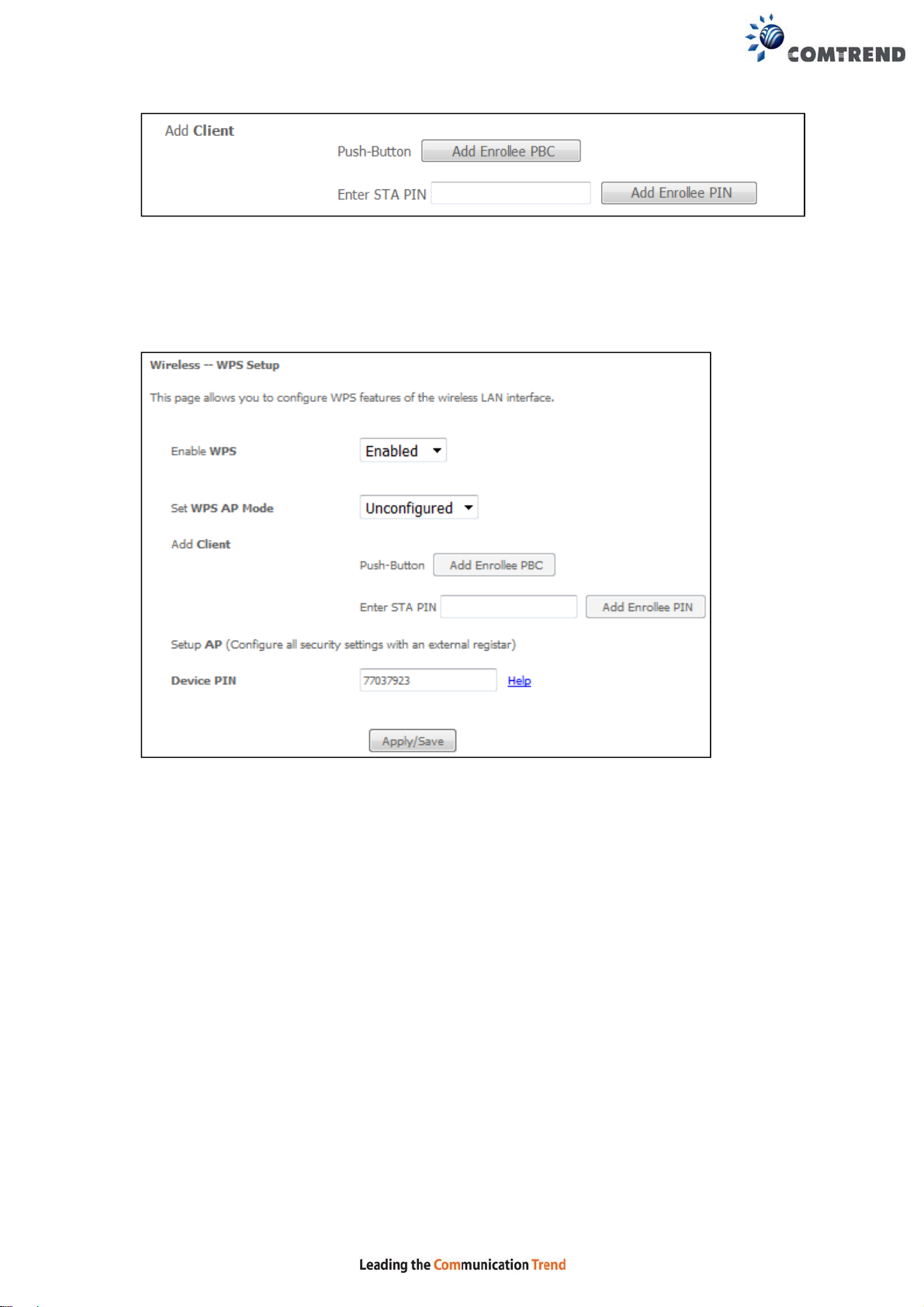
Enter the STA PIN and click the “Add Enrollee PIN” button to active PIN mode
connection
b. When enabled in unconfigured mode, enter the Device PIN to the external
registrar for PIN mode setup.
127
Page 26
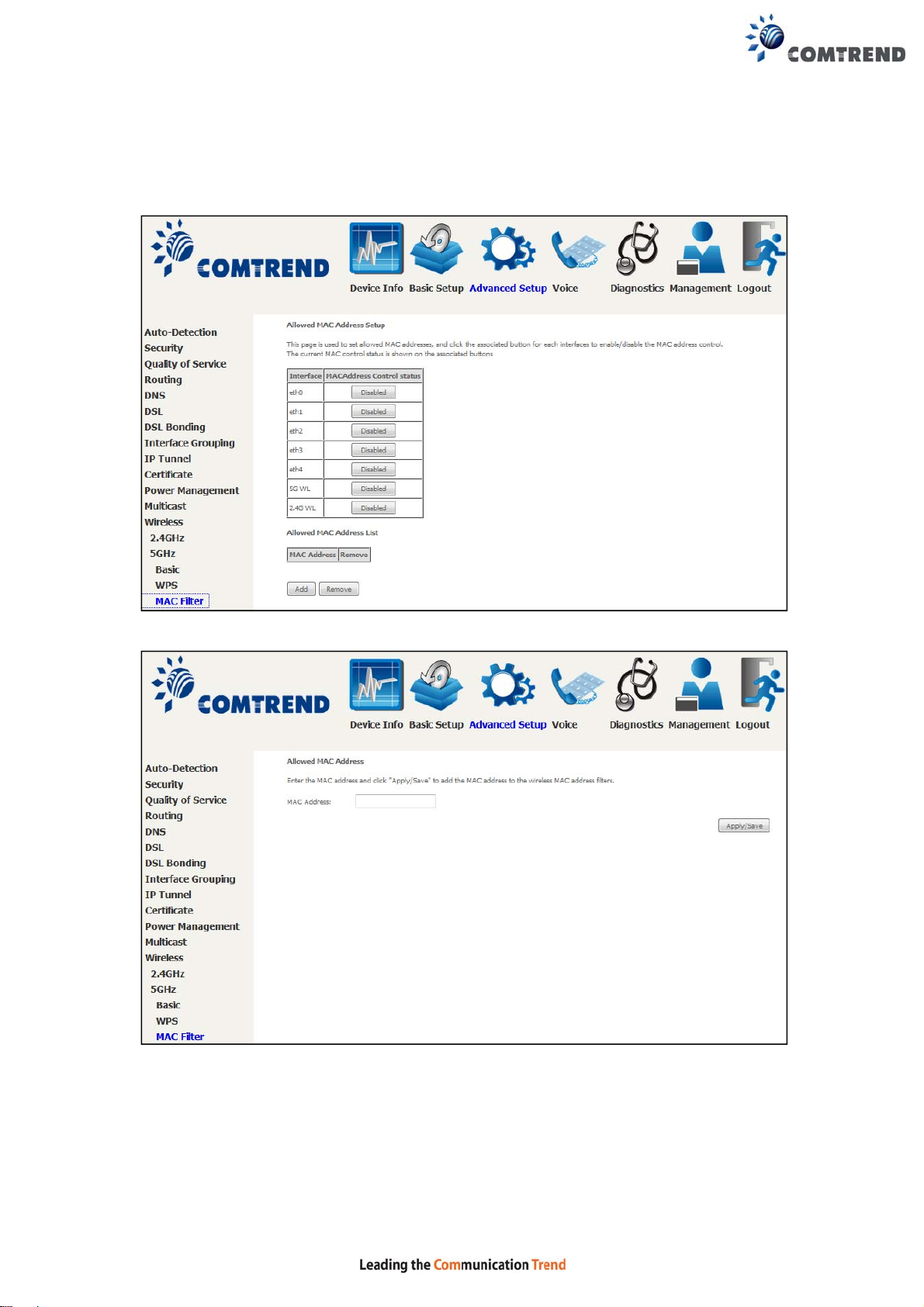
6.13.9 MAC Filter 5GHz
This page is used to set allowed MAC addresses, and click the associated button for
each interface to enable/disable the MAC address control.
The current MAC control status is shown on the associated buttons.
After clicking the Add button, the following screen appears.
Enter the MAC address in the box provided and click Apply/Save.
128
Page 27
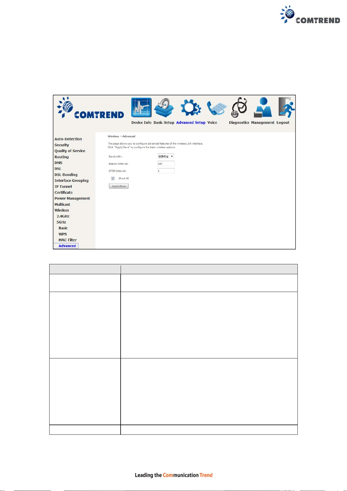
6.13.10 Advanced 5GHz
This page allows you to configure advanced features of the wireless LAN int erface.
Click Apply/Save to configure the basic wireless options.
Field Description
Bandwidth
Beacon Interval The amount of time between beacon transmissions in
DTIM Interval Delivery T raffic Indication Message (DTIM) is also known as
Short GI Enable/Disable use of short guard interval.
Select the bandwidth used on the 5G interface. 80MHz is
selected by default.
milliseconds. The default is 100 ms and the acceptable
range is 1 – 65535. The beacon transmissions identify the
presence of an access point. By default, network devices
passively scan all RF channels listening for beacons coming
from access points. Before a station enters power save
mode, the station needs the beacon interval to know when
to wake up to receive the beacon (and learn whether there
are buffered frames at the access point).
Beacon Rate. The entry range is a value between 1 and
65535. A DTIM is a countdown variable that informs clients
of the next window for listening to broadcast and multicast
messages. When the AP has buffered broadcast or
multicast messages for associated clients, it sends the next
DTIM with a DTIM Interval value. AP Clients hear the
beacons and awaken to receive the broadcast and
multicast messages. The default is 1.
129
Page 28
Chapter 7 Voice
This chapter first describes the various options for configuration of the SIP voice
service. It then provides detailed instructions for making telephone calls using VoIP
(Voice over IP) or PSTN (Public Switched Telephone Network) services. Session
Initiation Protocol (SIP) is a peer-to-peer protocol used for Internet conferencing,
telephony, events notification, presence and instant messaging.
SIP is designed to address the functions of signaling and session management
within a packet telephony network. Signaling allows call information to be carried
across network boundaries. Session management provides the ability to control
the attributes of an end-to-end call.
NOTE: The SIP standard is set by the Internet Engineering Task Force (IETF).
The SIP standard defines the following agents/servers:
• User Agents (UA) - SIP phone clients (hardware or software)
• Proxy Server – relays data between UA and external servers
• Registrar Server - a server that accepts register requests from UA
• Redirect Server – provides an address lookup service to UA
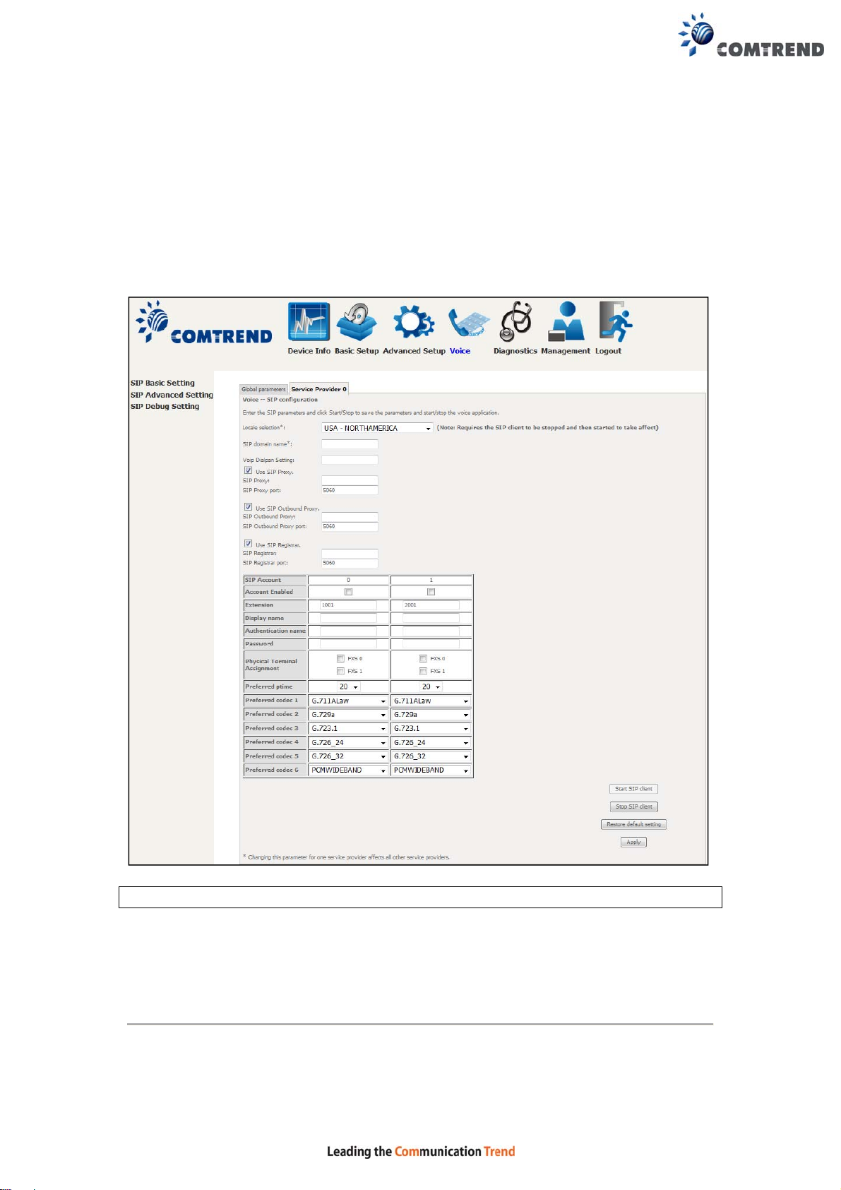
The following subsections present Basic, Advanced and Debug SIP screens.
Each screen provides various options for customizing the SIP configuration.
130
Page 29
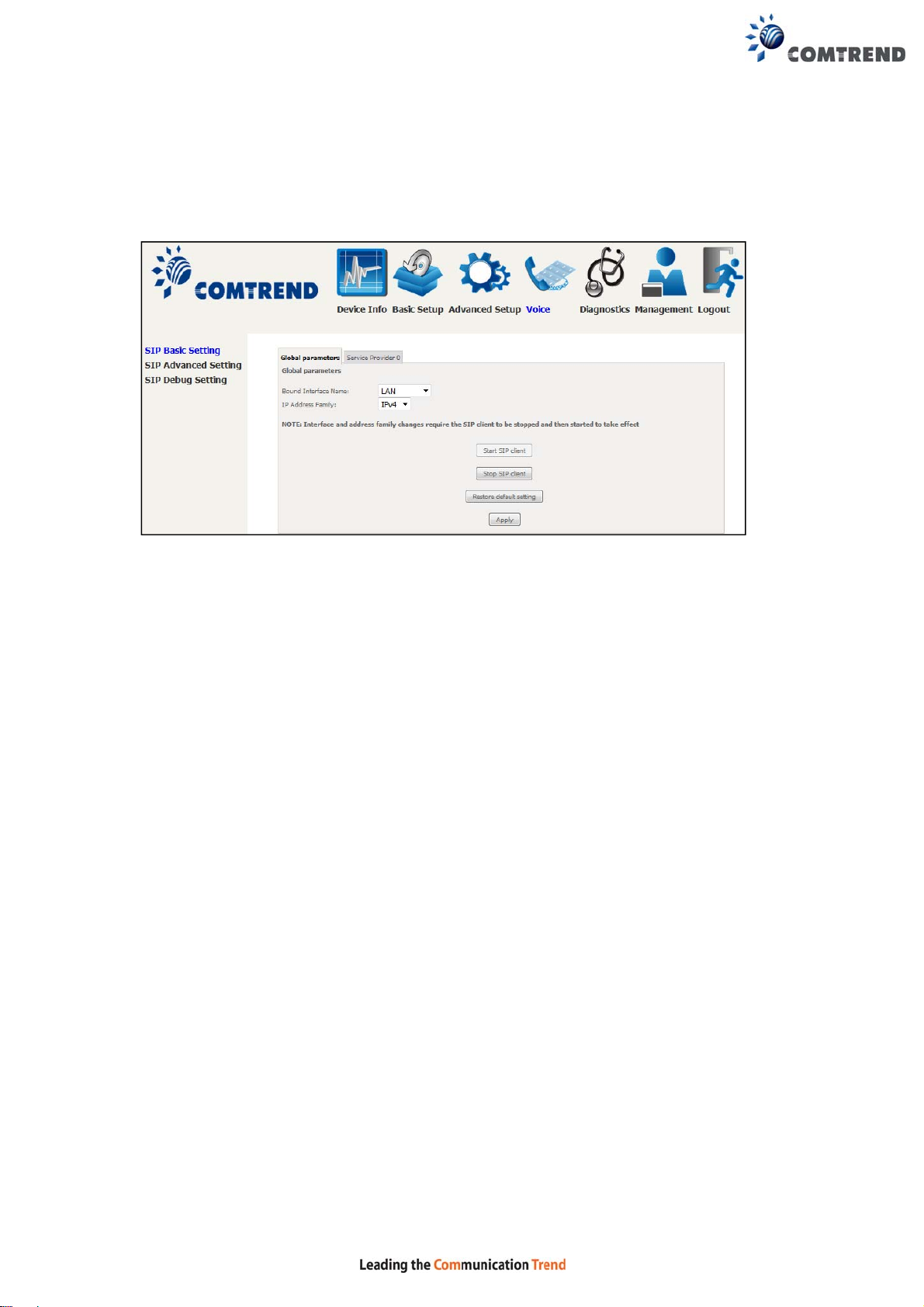
7.1 SIP Basic Setting – Global Parameters
A common parameter setting.
Bound Interface Name:
Select a WAN interface to send SIP control messages.
IP Address Family:
Select to use IPv4 or IPv6 for VoIP messages.
131
Page 30
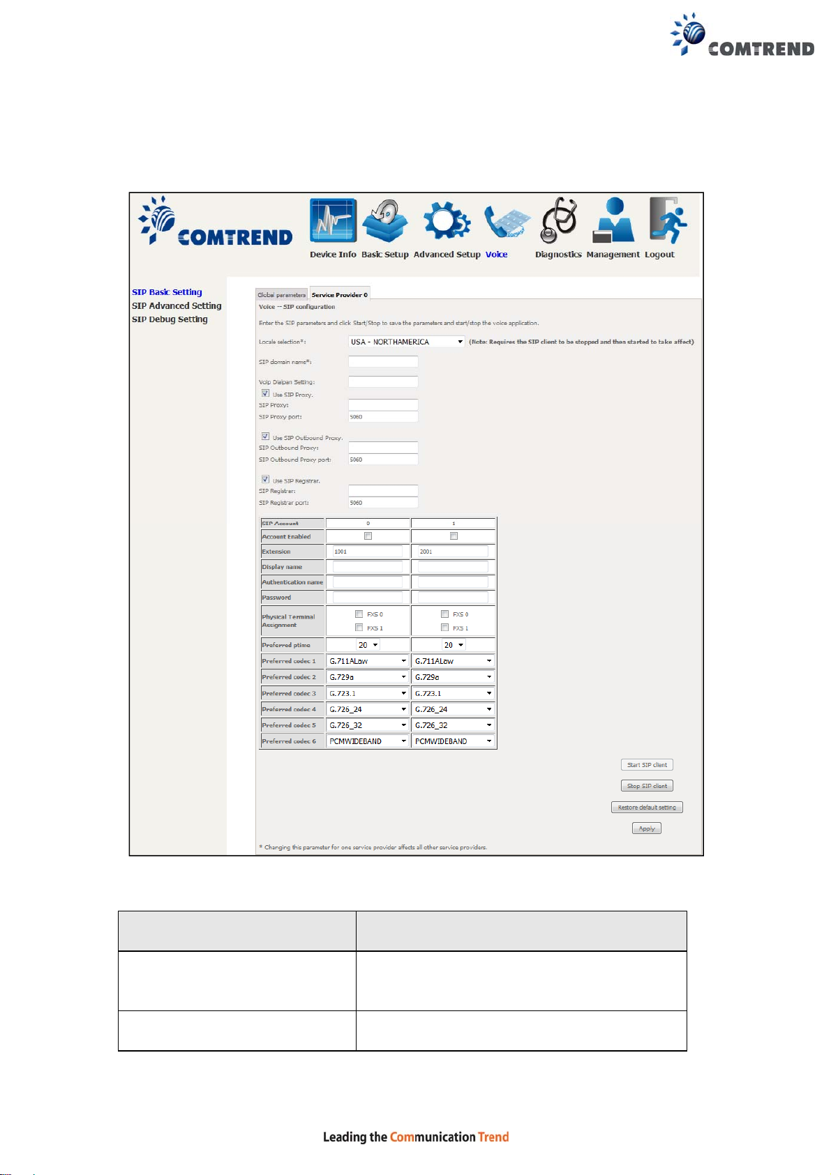
7.2 SIP Basic Setting – Service Provider
Enter the SIP parameters and click Start/Stop to save the parameters and start/stop
the voice application.
Once settings are configured click Apply to begin using the service.
Field Description
Locale Selection Sets tone, ring type and physical
characteristics for specific countries.
SIP domain name Provided by your VoIP provider.
132
Page 31

Field Description
VoIP Dialplan Setting A dial plan establishes the expected sequence
of digits dialed on subscriber premises
equipment, such as telephones, in private
branch exchange (PBX) systems, or in other
telephone switches to effect access to specific
telephone networks for telephone calls, and
to effect or activate specific telephone system
features.
In private branch exchanges in the U.S . a dial
plan may specify the dialing for the following
destinations:
• Internal extension numbers of two,
three, or four digits.
• Local numbers of seven or ten digits,
which may be preceded by a 9, if
Use SIP proxy
required to access an outside line.
• Long distance numbers of eleven
digits, consisting of a 1, a three-digit
area code, and a seven-digit number;
preceded by a 9 if required.
• International numbers of any length
starting with 011 and preceded by a 9
if required.
Similarly, telephony service operators may
provide dialing sequences for special
services, such as directory assistance and
emergency services.
PBX equipment, carrier switching systems, or
end-user telephones may specify a
variable-length dial plan or a fixed-length dial
plan.
Enable the SIP proxy by selecting the
checkbox and setting proxy parameters.
SIP Proxy Input IP address or domain name of the SIP
proxy server, used for VoIP service.
SIP Proxy port This value is set by your VoIP provider.
133
Page 32

Field Description
Enable the SIP outbound proxy by selecting
Use SIP Outbound Proxy
the checkbox and setting outbound proxy
parameters. It forwards the requests if you
cannot reach SIP proxy directly.
SIP Outbound Proxy port This value is set by your VoIP provider.
Use SIP Registrar
SIP Registrar
Enable the SIP Registrar proxy by selecting
the checkbox
Input IP address or domain name of the SIP
proxy server, used for VOIP service.
SIP Registrar Port This value is set by your VoIP provider.
FYI: A proxy is an intermediary program that acts as both a server a nd a client
for the purpose of making requests on behalf of other clients. Requests are
serviced internally or transferred to other servers. A proxy interprets and, if
necessary, rewrites a request message before forwarding it.
SIP Account 1 & 2 Ports FXS1 & FXS2
SIP Account Map SIP accounts to physical ports. “0”
represents to FXS1 and “1” represents to
FXS2.
Extension The line extension number.
Display Name The caller ID display name.
Authentication Name The authentication username for the
Registrar/Proxy, given by VoIP provider.
Authentication Password The authentication password for the
Registrar/proxy, given by VoIP provider.
Physical Terminal Assignment Connect the FXS port to the physical port.
Preferred ptime The time period used to digitally sample the
analog voice signal. The default is 20 ms.
Preferred codec 1-6 Choose from G.711MuLaw/ALaw, G.729a,
G.723.1, G.726_24/32, or GSM_AMR codecs
134
Page 33

7.3 SIP Advanced Setting – Global Parameters
This screen contains the advanced SIP configuration settings.
135
Page 34

7.4 SIP Advanced Setting – Service Provider
Configure your settings based on your service provider.
These settings are described in the tables below. Once configuration is complete,
click Apply to begin using the service.
NOTE: Some of these options can also be set using telephone k eypad commands,
as described in the call command list in section 7.7 Telephone Calls
Line 1 & 2 Ports FXS1 & FXS2
Call waiting
Tick the checkbox to enable this option.
136
Page 35

Line 1 & 2 Ports FXS1 & FXS2
Call forwarding number Enter the forwarding phone number.
Forward unconditionally Tick the checkbox to enable this option.
Forward on “busy” Tick the checkbox to enable this option.
Forward on “no answer” Tick the checkbox to enable this option.
Call barring Tick the checkbox to enable this option.
Call Barring allows you to bar certain types of calls from
being made from your phone and also allows you to bar
incoming calls.
Call barring pin The default setting for the Call Barring PIN code is the
same as the four-digit PIN code.
Call barring digit map Set the dial plan for call barring.
Warm line When the Warm Li ne function is in use, the user can di al
a number. Otherwise th e system will divert incoming
calls from an outside line to the Warm Line Number after
a set wait time.
Warm line number Define warm line number.
Anonymous call blocking Tick the checkbox to enable this option.
Anonymous calling Tick the checkbox to enable this option.
DND (Do Not Disturb) Tick the checkbox to enable this option.
Enable T38 support Enable or disable T38 Fax mode support with this
checkbox . You can plug a fax machine into either
phone port to send or receive faxes. Functionality
depends upon FAX support by your VoIP service
provider.
Enable V18 support Enable or disable for V18 support with this checkbox .
Registration Expire
Timeout
The time period the user would like the registration to
be valid for the Registrar/ Proxy Server. The default is
3600 seconds.
137
Page 36

Registration Retry
Interval
DSCP for SIP Diff Serv Code Point (DSCP) for SIP.
DSCP for RTP Diff Serv Code Point (DSCP) for RTP.
Dtmf Relay setting Set the special use of RTP packets to transmit digit
Hook Flash Relay setting Set flash hook event will be sent via which signal.
SIP Transport protocol SIP control message will be sent via which prot ocol.
SRTP Configuration Enable or disable for Security RTP support.
RFC 2198 Redundant
Level Configuration
Enable SIP tag matching
(Uncheck for Vonage
Interop).
The time interval between re-registration attempts.
events.
Enable or disable for RFC 2198 support.
Since CPE rely on the tags for matching purposes,
implementations which support Replacements MUST
support the SIP specification, which requires tags.
Music Server Set music server address for on-hold state.
Music Server port Set music server port for on-hold state.
Conference URI Set conference URI.
Conference Option Set conference option.
Secondary Outbound
Proxy IP
Secondary Outbound
Proxy Port
Set secondary outbound address.
Set secondary outbound port.
138
Page 37

7.5 SIP Debug Setting – Global Parameters
A common parameter setting.
Vodsl Console Log Level:
The log level allows users select what message will be shown in the log. It is
separated into 3 levels (Error, Notice and Debug).
139
Page 38

7.6 SIP Debug Setting – Service Provider
Configure your settings based on your service provider.
Once settings are configured, click Apply to begin using the service.
Checkbox Description
SIP log server
IP address & port
Enable Vad Support
Ingress gain Enhances the volume of speaking (the volume
Egress gain Enhances the volume of hearing.
Enter the IP address and port of the SIP log server.
Select the checkbox to enable VAD support.
Adjust the volume for incoming (Ingress) or
outgoing (Egress) gain with the drop-down boxes.
heard from the other side).
140
Page 39

7.7 Telephone Calls
To make a call, simply dial the number. The dial plan (i.e. the dialed digits) is
normally customized for each installation. The default dial plan allows for dialing of
4-digit extensions or direct IP addresses. For shorter extension numbers (e.g.
3-digits) adding a “#” at the end.
When a Call Server (SIP Proxy Server) is configured into the system, the dialed
digits are translated and routed by the Call Server to the correct destination as
registered with the Call Server.
If no Call Server is configured, calls can still be made using 4-digit extensions,
rather than using full IP addresses. The originator translates the dialed-digits to a
destination device as follows:
First Digit: Line identifier (for multi-line gateways)
Remaining digits: Host number part of an IP address. The Network number part
is considered to be the same as the caller’s IP address.
For example, if a caller at address 10.136.64.33/24 dials “2023”, the call will be
placed to the second line at address 10.136.64.23. All devices have to be on the
same Class C subnet (24-bit subnet mask).
T o dial an IP address directly, dial the IP address digits using * on the keypad as the
dot. Complete the address with a final * or #. When using IP address dialing it is not
possible to specify which line at a gateway is called, so the gateway always routes
IP-address dialed calls to the first line.
Network busy tone (fast busy) will be played for unknown or unreachable
destinations. To answer a call, pick up the phone or press the hands free button.
Caller ID
The Call Manager delivers Calling Number when placing calls. The calling number is
transmitted to the analog line for CLASS recognition.
Call Hold
To put a call on hold, press flash then hang up (optional). To return to the original
call, press flash or pick up the phone. The phone will issue a short ring burst every
30 seconds or so while on-hook to remind you that a call is on hold.
Call Transfer
• To transfer a call, press flash then dial the new number.
• To transfer immediately, hang up (blind transfer).
• T o transfer with cons ultation, wait for the party to answer, consult, and hang up.
• T o abort the transfer (if the third party does not answer); press fl ash to return to
the original call.
Conference Calling
To turn a two-party call into a three-party conference call, press flash and dial the
third party . Wait for the party to answer , then press flash. To drop the third party and
return to a two-party call, press flash again. T o drop yourself out of the conference,
hang up. The call will be tr ansferred (so that the other two parties remain connected
to each other). In conference mode, the conference initiator performs the audio
bridge/mixing function – there are only two voice streams established.
141
Page 40

Call Waiting
If call waiting is enabled on a line, and you hear the call waiting tone during a call,
press flash to answer the second call. The first call is automatically placed on hold.
To switch between calls, press flash again.
• To disable the call waiting feature, dial *60.
• To enable the call waiting feature, dial *61.
Call forward feature settings (Busy or All) takes priority over the call-waiting feature.
The call-waiting feature is ignored on new incoming calls if there is already a call on
hold or in conference.
Call Forward Number
• T o set the call forward number, dial *74 then the number . Note that this does not
actually enable forwarding; to do so, select the call forward action as described
below.
• To disable all call forwarding features, dial *70
Call Forward No Answer
• T o enable call forward on no answer, dial *71. Incoming calls will be forwarded
if unanswered for 18 seconds.
Call Forward Busy
• To enable call forward if busy, dial *72. Incoming calls will be immediately
forwarded if the phone is off-hook.
Call Forward All
• To enable call forward for all calls, dial *73.
• To disable the “forward all calls” feature, dial *75.
Previous settings for Call Forward Busy or No Answer are not modified.
Call Return
• To call the last known incoming caller (unanswered or not), dial *69.
Redial
• To redial the last outgoing number, dial *68.
VoIP to PSTN
• To dial a regular phone call over PSTN, you must first dial ##.
142
Page 41

Chapter 8 Diagnostics
You can reach this page by clicking on the following icon located at the top of the
screen.
8.1 Diagnostics – Individual Tests
The first Diagnostics screen is a dashboard that shows overall connection status.
Click the Diagnostics Menu item on the left side of the screen to display the
individual connections.
143
Page 42

8.2 Ethernet OAM
The Ethernet OAM page provides settings to enable/disable 802.3ah,
802.1ag/Y1.731 OAM protocols.
To enable Ethernet Link OAM (802.3 ah), click Enabled to display the full
configuration list. At least one option must be enabled for 802.1ah.
WAN Interface
OAM ID OAM Identification number
Auto Event Supports OAM auto event
Variable Retrieval Supports OAM variable retrieval
Link Events Supports OAM link events
Remote Loopback Supports OAM remove loopback
Active mode Supports OAM active mode
Select layer 2 WAN interface for outgoing OAM packets
144
Page 43

To enable Ethernet Service OAM (802.1ag/Y1731), click Enabled to display the full
configuration list.
Click Apply/Save to apply and save the settings.
WAN Interface
MD Level Maintenance Domain Level
MD Name Maintenance Domain name
MA ID Maintenance Association Identifier
Local MEP ID Local Maintenance association End Point Identifier
Local MEP VLAN ID VLAN IP used for Local Maintenance End point
Click CCM Transmission to enable CPE sending Continuity Check Message (CCM)
continuously.
Remote MEP ID
To perform Loopback/Linktrace OAM test, enter the Target MAC of the destination
and click “Send Loopback” or “Send Linktrace” button.
Target MAC
Linktrace TTL Time to Live value for the loopback/linktrace packet
Select from the list of WAN Interfaces to send OAM packets
Maintenance association End Point Identifier for the remote
receiver
MAC Address of the destination to send OAM
loopback/linktrace packet
145
Page 44

8.3 Uptime Status
This page shows System, DSL, ETH and Layer 3 uptime. If the DSL line, ETH or Layer
3 connection is down, the uptime will stop incrementing. If the service is restored,
the counter will reset and start from 0. A Bridge interface will follow the DSL or ETH
timer.
The "ClearAll" button will restart the counters fro m 0 or show "Not Connected" if the
interface is down.
146
Page 45

8.4 Ping
Input the IP address/hostname and click the Ping button to execute ping diagnostic
test to send the ICMP request to the specified host.
147
Page 46

8.5 Trace Route
Input the IP address/hostname and click the TraceRoute button to execute the
trace route diagnostic test to send the ICMP packets to the specified host.
148
Page 47

Chapter 9 Management
You can reach this page by clicking on the following icon located at the top of the
screen.
The Management menu has the following maintenance functions and processes:
9.1 Settings
This includes Backup Settings, Update Settings, and Restore Default screens.
9.1.1 Backup Settings
T o sa ve the current configuration to a file on your PC, click Backup Settings. You
will be prompted for backup file location. This file can later be used to recover
settings on the Update Settings screen, as described below.
149
Page 48

9.1.2 Update Settings
This option recovers configuration files previously saved using Backup Settings.
Enter the file name (including folder path) in the Settings File Name box, or press
Browse… to search for the file, then click Update Settings to recover settings.
9.1.3 Restore Default
Click Restore Default Settings to restore factory default settings.
After Restore Default Settings is clicked, the following screen appears.
Close the browser and wait for 2 minutes before reopening it. It may also be
necessary, to reconfigure your PC IP configuration to match any new settings.
150
Page 49

NOTE: This entry has the same effect as the Reset button. The NexusLink 3240
board hardware and the boot loader support the reset to default. If the
Reset button is continuously pressed for more than 10 seconds, the
current configuration data will be erased. If the Reset button is
continuously pressed for more than 60 seconds, the boot loader will erase
all configuration data saved in flash memory and enter bootloader mode.
151
Page 50

9.2 System Log
This function allows a system log to be kept and viewed upon request.
Follow the steps below to configure, enable, and view the system log.
STEP 1: Click Configure System Log, as shown below (circled in Red).
STEP 2: Select desired options and click Apply/Save.
Consult the table below for detailed descriptions of each system log option.
Option Description
Log Indicates whether the system is currently recording events. The user
can enable or disable event logging. By default, it is disabled. To
enable it, select the Enable radio button and then click Apply/Save.
152
Page 51

Option Description
Log
Level
Allows you to configure the event level and filter ou t unwanted events
below this level. The events ranging from the highest critical level
“Emergency” down to this configured level will be recorded to the log
buffer on the NexusLink 3240 SDRAM. When the log buffer is full, the
newer event will wrap up to the top of the log buffer and overwrite the old
event. By default, the log level is “Debugging”, which is the lowest critical
level.
The log levels are defined as follows:
• Emergency = system is unusable
• Alert = action must be taken immediately
• Critical = critical conditions
• Error = Error conditions
• Warning = normal but significant condition
• Notice= normal but insignificant condition
• Informational= provides information for reference
• Debugging = debug-level messages
Emergency is the most serious event level, whereas Debugging is the
least important. For instance, if the log level is set to Debugging, all the
events from the lowest Debugging level to the most critical level
Emergency level will be recorded. If the log level is set t o Error, only
Error and the level above will be logged.
Display
Level
Allows the user to select the logged events and displays on the View
System Log window for events of this level and above to the highest
Emergency level.
Mode Allows you to specify whether events should be stored in the local
memory, or be sent to a remote system log server, or both
simultaneously. If remote mode is selected, view system log will not be
able to display events saved in the remote system log server.
When either Remote mode or Both mode is configured, the WEB UI will
prompt the user to enter the Server IP address and Server UDP port.
STEP 3: Click View System Log. The results are displayed as follows.
153
Page 52

9.3 SNMP Agent
Simple Network Management Protocol (SNMP) allows a management application to
retrieve statistics and status from the SNMP agent in this device. Select the
Enable radio button, configure options, and click Save/Apply to activate SNMP.
154
Page 53

9.4 TR-069 Client
WAN Management Protocol (TR -069) allows an A uto-Configur ation Se rver (ACS) to
perform auto-configuration, provision, collection, and diagnostics to this device.
Select desired values and click Apply/Save to configure TR-069 client options.
The table below is provided for ease of reference.
Option Description
Enable TR-069 Tick the checkbox to enable.
OUI-serial The serial number used to identify the CPE when making a
connection to the ACS using the CPE WAN Management
Protocol. Select MAC to use the router’s MAC address as
serial number to authenticate with ACS or select serial
number to use router’s serial number.
Inform Disable/Enable TR-069 client on the CPE.
Inform Interval The duration in seconds of the interval for which the CPE
MUST attempt to connect with the ACS and call the Inform
method.
ACS URL URL for the CPE to connect to the ACS using the CPE WAN
Management Protocol. This parameter MUST be in the form
of a valid HTTP or HTTPS URL. An HTTPS URL indicates that
the ACS supports SSL. The “host” portion of this URL is
used by the CPE for validating the certificate from the ACS
when using certificate-based authentication.
155
Page 54

Option Description
ACS User Name Username used to authenticate the CPE when making a
connection to the ACS using the CPE WAN Management
Protocol. This username is used only for HTTP-based
authentication of the CPE.
ACS Password Password used to authenticate the CPE when making a
connection to the ACS using the CPE WAN Management
Protocol. This password is used only for HTTP-based
authentication of the CPE.
WAN Interface used
by TR-069 client
Connection Request
Authentication Tick the checkbox to enable.
User Name Username used to authenticate an ACS making a
Password Password used to authenticate an ACS making a
URL IP address and port the ACS uses to connect to router.
The Send Inform button forces the CPE to establish an immediate connection to
the ACS.
Choose Any_WAN, LAN, Loopback or a configured
connection.
Connection Request to the CPE.
Connection Request to the CPE.
156
Page 55

9.5 Internet Time
This option automatically synchronizes the router time with Internet timeservers.
To enable time synchronization, tick the corresponding checkbox , choose your
preferred time server(s), select the correct time zone offset, and click Apply/Save.
NOTE: Internet Time must be activated to use See 5.5 Parental Control.
The internet time feature will not operate when router is in bridged mode, since the
route would not be able to connect to the NTP timeserver.
157
Page 56

9.6 Access Control
9.6.1 Accounts
This screen is used to configure the user account access passwords for the device.
Access to the NexusLink 3240 is controlled through the following user accounts:
• The root account has unrestricted access to view and change the
configuration of your Broadband router.
• The support account is typically utilized by Carrier/ISP technicians for
maintenance and diagnostics.
• The user account is typically utilized by End-Users to view configuration
settings and statistics, with limited ability to configure certain settings.
• The apuser account is typically util ized by End-Users to vi ew configur ation
settings and statistics, with limited ability to configure wireless settings.
Use the fields to update passwords for the accounts, add/remove accounts (max of
5 accounts) as well as adjust their specific privileges.
158
Page 57

Note: Passwords may be as long as 16 characters but must not contain a space.
Click Save/Apply to continue.
159
Page 58

9.6.2 Services
The Services option limits or opens the access services over the LAN or WAN. The
access services available are: HTTP, SSH, TELNET, SNMP , HTTPS , FTP , TFTP and ICMP.
Enable a service by selecting its dropdown listbox. Click Apply/Save to activat e.
160
Page 59

9.6.3 IP Address
The IP Address Access Control mode, if enabled, permits access to local
management services from IP addresses contained in the Access Control List. If the
Access Control mode is disabled, the system will not validate IP addresses for
incoming packets. The services are the system applications listed in the Service
Control List beside ICMP.
Click the Add button to display the following.
Configure the address and subnet of the management station permitted to access
the local management services, and click Save/Apply.
IP Address – IP address of the management station.
Subnet Mask – Subnet address for the management station.
Interface – Access permission for the specified address, allowing the address to
access the local management service from none/lan/wan/lan&wan interfaces.
161
Page 60

9.7 Wake-on-LAN
This tool allows you to wake up (power on) computers connected to the Broadband
Router LAN interface by sending special "magic packets".
The network interface card in the computer or device that is going to be woken up
must support Wake-on-LAN.
LAN Interface – Select the LAN interface to send the Wake-on-LAN packet.
MAC Address – Specify the MAC address of the device that is going to be woken up.
Click “Send WoL magic packet to the Broadcast address” if the WoL packets
should be sent to the broadcast address.
Click the Wake Up! button to send the magic packet out to the LAN interface.
162
Page 61

9.8 Update Software
This option allows for firmware upgrades from a locally stored file.
STEP 1: Obtain an updated software image file from your ISP.
STEP 2: Select the configuration from the drop-down menu.
Configuration options:
No change – upgrade software directly.
Erase current config – If the router has save_default configuration, this option will
erase the current configuration and restore to save_default configuration after
software upgrade.
Erase All – Router will be restored to factory default configuration after software
upgrade.
STEP 3: Enter the path and filename of the firmware image file in the Software
File Name field or click the Browse button to locate the image file.
STEP 4: Click the Update Software button once to upload and install the file.
NOTE: The update process will take about 2 minutes to complete. The device
will reboot and the browser window will refresh to the default screen upon
successful installation. It is recommended that you compare the
Software Version on the Device Information screen with the firmware
version installed, to confirm the installation was successful.
163
Page 62

9.9 Reboot
To save the current configuration and reboot the router, click Reboot.
NOTE: You may need to close the browser window and wait for 2 minutes before
reopening it. It may also be necessary, to reset your PC IP configuration.
164
Page 63

Chapter 10 Logout
To log out from the device simply click the following icon located at the top of your
screen.
When the following window pops up, click the OK button to exit the router.
Upon successful exit, the following message will be displayed.
165
Page 64

Appendix A - Firewall
STATEFUL PACKET INSPECTION
Refers to an architecture, where the firewall keeps track of packets on each
connection traversing all its interfaces and makes sure they are valid. This is in
contrast to static packet filtering which only examines a packet based on the
information in the packet header.
DENIAL OF SERVICE ATTACK
Is an incident in which a user or organization is deprived of the services of a
resource they would normally expect to have. Various DoS attacks the device can
withstand are ARP Attack, Ping Attack, Ping of Death, Land, SYN Attack, Smurf
Attack, and Tear Drop.
TCP/IP/PORT/INTERFACE FILTER
These rules help in the filtering of traffic at the Network layer (i.e. Layer 3).
When a Routing interface is created, Enable Firewall must be checked.
Navigate to Advanced Setup Security IP Filtering.
OUTGOING IP FILTER
Helps in setting rules to DROP packets from the LAN interface. By default, if the
Firewall is Enabled, all IP traffic from the LAN is allowed. By setting up one or more
filters, specific packet types coming from the LAN can be dropped.
Example 1
This filter will Drop all TCP packets coming from the LAN with IP
Address/Subnet Mask of 192.168.1.45/24 having a source port of 80
irrespective of the destination. All other packets will be Accepted.
Example 2
This filter will drop all UDP packets coming from the LAN with IP Address /
Subnet Mask of 192.168.1.45/24 and a source port range of 5060 to 6060,
destined to 172.16.13.4/24 and a destination port range of 6060 to 7070.
: Filter Name : Out_Filter1
Protocol : TCP
Source IP address : 192.168.1.45
Source Subnet Mask : 255.255.255.0
Source Port : 80
Dest. IP Address : NA
Dest. Subnet Mask : NA
Dest. Port : NA
: Filter Name : Out_Filter2
Protocol : UDP
Source IP Address : 192.168.1.45
Source Subnet Mask : 255.255.255.0
Source Port : 5060:6060
Dest. IP Address : 172.16.13.4
Dest. Subnet Mask : 255.255.255.0
Dest. Port : 6060:7070
INCOMING IP FILTER
Helps in setting rules to Allow or Deny packets from the WAN interface. By default,
all incoming IP traffic from the WAN is Blocked, if the Firewall is Enabled. By setting
up one or more filters, specific packet types coming from the WAN ca n be Accepted.
166
Page 65

Example 1: Filter Name : In_Filter1
Protocol : TCP
Policy : Allow
Source IP Address : 210.168.219.45
Source Subnet Mask : 255.255.0.0
Source Port : 80
Dest. IP Address : NA
Dest. Subnet Mask : NA
Dest. Port : NA
Selected WAN interface : br0
This filter will ACCEPT all TCP packets coming from WAN interface “br0” with I P
Address/Subnet Mask 210.168.219.45/16 with a source port of 80, irrespective
of the destination. All other incoming packets on this interface are DROPPED.
Example 2
: Filt er Name : In_Filter2
Protocol : UDP
Policy : Allow
Source IP Address : 210.168.219.45
Source Subnet Mask : 255.255.0.0
Source Port : 5060:6060
Dest. IP Address : 192.168.1.45
Dest. Sub. Mask : 255.255.255.0
Dest. Port : 6060:7070
Selected WAN interface : br0
This rule will ACCEPT all UDP packets coming from WAN interface “br0” with IP
Address/Subnet Mask 210.168.219.45/16 and a source port in the range of
5060 to 6060, destined to 192.168.1.45/24 and a destination port in the range
of 6060 to 7070. All other incoming packets on this interface are DROPPED.
MAC LAYER FILTER
These rules help in the filtering of Layer 2 traffic. MAC Filtering is only effective in
Bridge mode. After a Bridge mode connection is created, navigate to Advanced
Setup Security MAC Filtering in the WUI.
Example 1
: Global Policy : Forwarded
Protocol Type : PPPoE
Dest. MAC Address : 00:12:34:56:78:90
Source MAC Address : NA
Src. Interface : eth1
Dest. Interface : eth2
Addition of this rule drops all PPPoE frames going from eth1 to eth2 with a
Destination MAC Address of 00:12:34:56:78:90 irrespective of its Source MAC
Address. All other frames on this interface are forwarded.
Example 2
: Global Policy : Blocked
Protocol Type : PPPoE
Dest. MAC Address : 00:12:34:56:78:90
Source MAC Address : 00:34:12:78:90:56
Src. Interface : eth1
Dest. Interface : eth2
Addition of this rule forwards all PPPoE frames going from eth1 to eth2 with a
Destination MAC Address of 00:12:34:56:78 and Source MAC Address of
00:34:12:78:90:56. All other frames on this interface are dropped.
167
Page 66

DAYTIME PARENTAL CONTROL
This feature restricts access of a selected LAN device to an outside Network through
the NexusLink 3240, as per chosen days of the week and the chosen times.
Example
: User Name : FilterJohn
Browser's MAC Address : 00:25:46:78:63:21
Days of the Week : Mon, Wed, Fri
Start Blocking Time : 14:00
End Blocking Time : 18:00
With this rule, a LAN device with MAC Address of 00:25:46:78:63:21 will have
no access to the WAN on Monda ys, Wednesdays, and Fridays, from 2p m to 6pm.
On all other days and times, this device will have access to the outside
Network.
168
Page 67

Appendix B - Pin Assignments
Giga ETHERNET Ports (RJ45)
Pin Name Description
1 BI_DA+ Bi-directional pair A +
2 BI_DA- Bi-directional pair A 3 BI_DB+ Bi-directional pair B +
4 BI_DC+ Bi-directional pair C +
5 BI_DC- Bi-directional pair C 6 BI_DB- Bi-directional pair B 7 BI_DD+ Bi-directional pair D +
8 BI_DD- Bi-directional pair D -
169
Page 68

Appendix C – Specifications
Hardware Interface
RJ-14 X 1 for ADSL2+ bonding/VDSL2, RJ-45 X 4 for LAN, RJ-45 X 1 for W AN,
FXS X 2, Reset Button X 1, WPS/WiFi on/off button x2, Internal Wi-Fi
Antennas X 2, External Wi-Fi Antennas X 2, Power Switch X 1, USB 3 .0 Host
X 1
WAN Interface
ADSL2+: single line and bonding
VDSL2 17a, single line and bonding
10/100/1000 Base T, IEEE 802.3, IEEE 802.3u IEEE 802.3ab
LAN Interface
Standard ..................... IEEE 802.3, IEEE 802.3u, IEEE 802.3ab
10/100/1000 BaseT ...... Auto-sense
MDI/MDX support ......... Yes
WLAN Interface
Standard ................... IEEE802.11b/g/n
Encryption................... 64/128-bit Wired Equivalent Privacy (WEP)
Channels ..................... 11 (US, Canada)/ 13 (Europe)/ 14 (Japan)
Data Rate ................... Up to 300Mbps
WEP ........................... Yes
WPA ........................... Yes
IEEE 802.1x ................ Yes
MAC Filtering ............... Yes
ATM Attributes
RFC 2684 (RFC 1483) Bridge/Route; RFC 2516 (PPPoE);
RFC 2364 (PPPoA); RFC 1577 (IPoA)
PVCs ......................... 16
AAL type ..................... AAL5
ATM service class ......... UBR/CBR/VBR
ATM UNI support .......... UNI 3.1/4.0
OAM F4/F5 .................. Yes
Management
Compliant with TR-069/TR-098/TR-104/TR-111 remote management
protocols, Telnet, Web-based management, Configuration backup and
restoration, Software upgrade via HTTP / TFTP / FTP server
Bridge Functions
Transparent bridging .............................. Yes
VLAN support ....................................... Yes
Spanning Tree Algorithm ........................ Yes
170
Page 69

IGMP Proxy .......................................... Yes
Routing Functions
Static route, RIP v1/v2, NAT/PAT, DHCP Server/Relay, DNS Proxy, ARP,
Security Functions
Authentication protocols: PAP, CHAP
TCP/IP/Port filtering rules, Packet and MAC address filtering, Access Control,
QoS
IP QoS, L3 policy-based QoS, ToS
Environment Condition
Operating temperature ........................... 0 ~ 40 degrees Celsius
Relative humidity .................................. 5 ~ 95% (non-condensing)
Dimensions .................................... 280 mm (W) x 35 mm (H) x 210 mm (D)
Kit Weight
(1* NexusLink 3240, 1*RJ11 cable, 1*RJ45 cable, 1*power adapter) = 1.2 kg
NOTE: Specifications are subject to change without notice.
171
Page 70

Appendix D - SSH Client
Unlike Microsoft Windows, Linux OS has a ssh client included . For Windows users,
there is a public domain one called “putty” that can be downloaded from here:
http://www.chiark.greenend.org.uk/~sgtatham/putty/download.html
To access the ssh client you must first enable SSH access for the LAN or WAN from
the Management Access Control Services menu in the web user interface.
To access the router using the Linux ssh client
For LAN access, type: ssh -l root 192.168.1.1
For WAN access, type: ssh -l support WAN IP address
To access the router using the Windows “putty” ssh client
For LAN access, type: putty -ssh -l root 192.168.1.1
For WAN access, type: putty -ssh -l support WAN IP address
NOTE: The WAN IP address can be found on the Device Info WAN screen
172
Page 71

Appendix E - Printer Server
These steps explain the procedure for enabling the Printer Server.
NOTE: This function only appli es to models with a USB host port.
STEP 1: Enable Print Server from Web User Interface. Select Enable on-board
print server checkbox and enter Printer name and Make and model.
Click the Apply/Save button.
NOTE: The Printer name can be any text string up to 40 characters.
The Make and model can be any text string up to 128 characters.
STEP 2: Go to the Printers and Faxes application in the Control Panel and
select the Add a printer function (as located on the side menu below).
173
Page 72

STEP 3: Click Next to continue when you see the dialog box below.
STEP 4: Select Network Printer and click Next.
174
Page 73

STEP 5: Select Connect to a printer on the Internet and enter your printer link.
(e.g. http://192.168.1.1:631/printers/hp3845) and click Next.
NOTE: The printer name must be the same name entered in the ADSL modem
WEB UI “printer server setting” as in step 1.
STEP 6: Click Have Disk and insert the printer driver CD.
175
Page 74

STEP 7: Select driver f ile directory on CD-ROM and click OK.
STEP 8: Once the printer name appears, click OK.
176
Page 75

STEP 9: Choose Yes or No for default printer setting and click Next.
STEP 10: Click Finish.
177
Page 76

STEP 11: Check the status of printer from Windows Control P anel, prin ter window .
Status should show as Ready.
178
Page 77

Appendix F - Connection Setup
Creating a WAN connection is a two-stage process.
1 - Setup a Layer 2 Interface (ATM, PTM or Ethernet).
2 - Add a WAN connection to the Layer 2 Interface.
The following sections describe each stage in turn.
F1 ~ Layer 2 Interfaces
Every layer2 interface operates in Multi-Service Connection (VLAN MUX) mode,
which supports multiple connections over a single interface. Note that PPPoA and
IPoA connection types are not supported for Ethernet W AN i nterfaces. After adding
WAN connections to an interface, you must also create an Interface Group to
connect LAN/WAN interfaces.
F1.1 ATM Interfaces
Follow these procedures to configure an ATM interface.
NOTE: The NexusLink 3240 supports up to 16 ATM interfaces.
STEP 1: Go to Basic Setup WAN Setup Select ATM Interface from
the drop-down menu.
This table is provided here for ease of reference.
179
Page 78

Heading Description
Interface WAN interface name
VPI ATM VPI (0-255)
VCI ATM VCI (32-65535)
DSL Latency {Path0} portID = 0
{Path1} port ID = 1
{Path0&1} port ID = 4
Category ATM service category
Peak Cell Rate Maximum allowed traffic rate for the ATM PCR service
connection
Sustainable Cell
Rate
The average allowable, long-term cell tr ansfer rate on the VBR
service connection
Max Burst Size The maximum allowable burst size of cells that can be
transmitted continuously on the VBR service connection
Link Type Choose EoA (for PPPoE, IPoE, and Bridge), PPPoA, or IPoA.
Connection Mode Default Mode – Single service over one connection
Vlan Mux Mode – Multiple Vlan service over one connection
IP QoS Quality of Service (QoS) status
Remove Select items for removal
STEP 2: Click Add to proceed to the next screen.
NOTE: To add WAN connections to one interface type, you must delete existing
connections from the other interface type using the remove button.
180
Page 79

There are many settings here including: VPI/VCI, DSL Link Type, Encapsulation
Mode, Service Category and Queue Weight.
Here are the available encapsulations for each xDSL Link Type:
EoA- LLC/SNAP-BRI DG ING, VC/MUX
PPPoA- VC/MUX, LLC/ENCAPSULATION
IPoA- LLC/SNAP-ROUTING, VC MUX
STEP 3: Click Apply/Save to confirm your choices.
On the next screen, check that the A TM interfa ce is added to the l ist. For example,
an ATM interface on PV C 0/35 in Default Mode with an EoA Link type is shown below.
181
Page 80

To add a WAN connection go to Section F2 ~ WAN Connections.
F1.2 PTM Interfaces
Follow these procedures to configure a PTM interface.
NOTE: The NexusLink 3240 supports up to four PTM interfaces.
STEP 1: Go to Basic Setup WAN Setup Select PTM Interface from
the drop-down menu.
This table is provided here for ease of reference.
Heading Description
Interface WAN interface name.
182
Page 81

Heading Description
DSL Latency {Path0} portID = 0
{Path1} port ID = 1
{Path0&1} port ID = 4
PTM Priority Normal or High Priority (Preemption).
Connection Mode Default Mode – Single service over one interface.
Vlan Mux Mode – Multiple Vlan services over one interface.
IP QoS Quality of Service (QoS) status.
Remove Select interfaces to remove.
STEP 2: Click Add to proceed to the next screen.
NOTE: To add WAN connections to one in terface type, you must delete existing
connections from the other interface type using the remove button.
Default PTM interface Quality of Service can be configured here, including Scheduler ,
Queue Weight and Rate Limit.
STEP 3: Click Apply/Save to confirm your choices.
On the next screen, check that the PTM interface is added to the list.
For example, a PTM interface in Default Mode is shown below.
To add a WAN connection go to Section F2 ~ WAN Connections.
183
Page 82

F1.3 Ethernet WAN Interface
The NexusLink 3240 supports a single Ethernet WAN interface over the ETH WAN
port. Follow these procedures to configure an Ethernet interface.
STEP 1: Go to Basic Setup WAN Setup Select ETHERNET Interface
from the drop-down menu.
This table is provided here for ease of reference.
Heading Description
Interface/ (Name) WAN interface name.
Connection Mode Default Mode – Single service over one interface.
Vlan Mux Mode – Multiple Vlan services over one interface.
Remove Select interfaces to remove.
STEP 2: Click Add to proceed to the next screen.
STEP 3: Select an Ethernet port and Click Apply/Save to confirm your choices.
184
Page 83

On the next screen, check that the ETHERNET interface is added to the list.
To add a WAN connection go to Section F2 ~ WAN Connections.
185
Page 84

F2 ~ WAN Connections
The NexusLink 3240 supports one WAN connection for each interface, up to a
maximum of 16 connections.
To setup a WAN connection follow these instructions.
STEP 1: Go to Basic Setup WAN Setup.
STEP 2: Click Add to create a WAN connection. The following screen will display.
STEP 3: Choose a layer 2 interface from the drop-down box and click Next.
The WAN Service Configuration screen will display as shown below.
186
Page 85

NOTE: The WAN services shown here are those supported by the layer 2
interface you selected in the previous step. If you wish to change your
selection click the Back button and select a different layer 2 interface.
STEP 4: For VLAN Mux Connections only, you must enter Priority & VLAN ID tags.
Select a TPID if VLAN tag Q-in-Q is used.
STEP 5: You will now follow the instructions specific to the WAN service type you
wish to establish. This list should help you locate the correct procedure:
(1) For F2.1 PPP over ETHERNET (PPPoE), go to page 186.
(2) For F2.2 IP over ETHERNET (IPoE), go to page 192.
(3) For F2.3 Bridging, go to page 198.
(4) For F2.4 PPP over ATM (PPPoA), go to page 200.
(5) For F2.5 IP over ATM (IPoA), go to page 206.
The subsections that follow continue the WAN service setup procedure.
187
Page 86

F2.1 PPP over ETHERNET (PPPoE)
STEP 1: Select the PPP over Ethernet radio button and click Next. You can also
enable IPv6 by selecting from the drop-down box at the bottom of this
screen.
STEP 2: On the next screen, enter the PPP settings as provided by your ISP.
Click Next to continue or click Back to return to the previous step.
188
Page 87

Click Next to continue or click Back to return to the previous step.
The settings shown above are described below.
PPP SETTINGS
The PPP Username, PPP password and the PPPoE Service Name entries are
dependent on the particular requirements of the ISP. The user name can be a
maximum of 256 characters and the password a maximum of 32 characters in
length. For Authentication Method, choose from AUTO, PAP, CHAP, and MSCHAP.
189
Page 88

ENABLE FULLCONE NAT
This option becomes available when NAT is enabled. Known as one-to-one NAT, all
requests from the same internal IP address and port are mapped to the same
external IP address and port. An external host can send a packet to the internal host,
by sending a packet to the mapped external address.
DIAL ON DEMAND
The NexusLink 3240 can be configured to disconnect if there is no activity for a
period of time by selecting the Dial on demand checkbox . You must also e nter
an inactivity timeout period in the range of 1 to 4320 minutes.
PPP IP EXTENSION
The PPP IP Extension is a special feature deployed by some service providers.
Unless your service provider specifically requires this setup, do not select it.
PPP IP Extension does the following:
• Allows only one PC on the LAN.
• Disables NAT and Firewall.
• The device becomes the default gateway and DNS server to the PC
through DHCP using the LAN interface IP address.
• The device extends the IP subnet at the remote service provider to the
LAN PC. i.e. the PC becomes a host belonging to the same IP subnet.
• The device bridges the IP packets between WAN and LAN ports, unless
the packet is addressed to the device’s LAN IP address.
• The public IP address assigned by the remote side using the PPP/IPCP
protocol is actually not used on the WAN PPP interface. Instead, it is
forwarded to the PC LAN interface through DHCP. Only one PC on the
LAN can be connected to the remote, since the DHCP server within the
device has only a single IP address to assign to a LAN device.
ENABLE NAT
If the LAN is configured with a private IP address, the user should select this
checkbox . The NA T submenu will appear in the Advanced Setup menu after reboot.
On the other hand, if a private IP address is no t used on the LAN side (i.e. the LAN
side is using a public IP), this checkbox should not be selected to free up system
resources for better performance.
ENABLE FIREWALL
If this checkbox is selected, the Security submenu will be displayed on the
Advanced Setup menu after reboot. If firewall is not necessary, this checkbox
should not be selected to free up system resources for better performance.
USE STATIC IPv4 ADDRESS
Unless your service provider specially requires it, do not select this checkbox . If
selected, enter the static IP address in the IPv4 Address field.
Don’t forget to adjust the IP configuration to Static IP Mode as described in section
3.2 IP Configuration.
FIXED MTU
Maximum Transmission Unit. The size (in bytes) of largest protocol data unit which
the layer can pass onwards. This value is 1492 for PPPoE.
190
Page 89

ENABLE PPP DEBUG MODE
When this option is selected, the system will put more PPP connection information
into the system log. This is for debugging errors and not for normal usage.
BRIDGE PPPOE FRAMES BETWEEN WAN AND LOCAL PORTS
(This option is hidden when PPP IP Extension is enabled
)
When Enabled, this creates local PPPoE connections to the WAN side. Enable this
option only if all LAN-side devices are running PPPoE clients, otherwise disable it.
The NexusLink 3240 supports pass-through PPPoE sessions from the LAN side while
simultaneously running a PPPoE client from non-PPPoE LAN devices.
ENABLE IGMP MULTICAST PROXY
Tick the checkbox to enable Internet Group Membership Protocol (IGMP)
multicast. This protocol is used by IPv4 hosts to report their multicast group
memberships to any neighboring multicast routers.
Enable IGMP Multicast Source
Enable the WAN interface to be used as IGMP multicast source.
STEP 3: Choose an interface to be the default gateway.
Click Next to continue or click Back to return to the previous step.
191
Page 90

STEP 4: Select DNS Server Interface from available WAN interfaces OR enter
static DNS server IP addresses for the system. In ATM mode, if only a
single PVC with IPoA or static IPoE protocol is configured, Static DNS
server IP addresses must be entered.
Click Next to continue or click Back to return to the previous step.
192
Page 91

STEP 5: The WAN Setup - Summary screen sh ows a preview of the WAN service
you have configured. Check these setti ngs and cli ck Apply/Save if they
are correct, or click Back to modify them.
After clicking Apply/Save, the new service should appear on the main screen.
193
Page 92

F2.2 IP over ETHERNET (IPoE)
STEP 1: *Select the IP over Ethernet radio button and click Next.
*
For tagged service, enter valid 802.1P Priority and 802.1Q VLAN ID.
For untagged service, set -1 to both 802.1P Priority and 802.1Q VLAN ID.
194
Page 93

STEP 2: The WAN IP settings screen provides access to the DHCP server settings.
Y ou can select the Obtain an IP address automatically radio button to
enable DHCP (use the DHCP Options only if necessary). However, if you
prefer , you c an use the Static IP address method instead to assign WAN
IP address, Subnet Mask and Default Gateway manually.
NOTE: If IPv6 networking is enabled, an additional set of instructions, radio
buttons, and text entry boxes will appear at the bottom of the screen.
These configuration options are quite similar to those for IPv4 networks.
Click Next to continue or click Back to return to the previous step.
195
Page 94

STEP 3: This screen provides access to NA T, Firewall and IGMP Multicast setti ngs.
Enable each by selecting the appropriate checkbox . Click Next to
continue or click Back to return to the previous step.
ENABLE NAT
If the LAN is configured with a private IP address, the user should select this
checkbox . The NAT submenu will appear in the Advanced Setup menu after
reboot. On the other hand, if a private IP address is not used on the LAN side (i.e.
the LAN side is using a public IP), this checkbox should not be selected, so as to
free up system resources for improved performance.
ENABLE FULLCONE NAT
This option becomes available when NAT is enabled. Known as one-to-one NAT, all
requests from the same internal IP address and port are mapped to the same
external IP address and port. An external host can send a packet to the internal host,
by sending a packet to the mapped external address.
ENABLE FIREWALL
If this checkbox is selected, the Security submenu will be displayed on the
Advanced Setup menu after reboot. If firewall is not necessary, this checkbox
should not be selected so as to free up system resources for better performance.
ENABLE IGMP MULTICAST PROXY
Tick the checkbox to enable Internet Group Membership Protocol (IGMP)
multicast. This protocol is used by IPv4 hosts to report their multicast group
memberships to any neighboring multicast routers.
Enable IGMP Multicast Source
Enable the WAN interface to be used as IGMP multicast source.
196
Page 95

STEP 4: To choose an interface to be the default gateway.
Click Next to continue or click Back to return to the previous step.
197
Page 96

STEP 5: Select DNS Server Interface from available WAN interfaces OR enter static
DNS server IP addresses for the system. In A TM mode, if only a single PVC with IPoA
or static IPoE protocol is configured, Static DNS server IP addresses must be
entered.
Click Next to continue or click Back to return to the previous step.
198
Page 97

STEP 6: The WAN Setup - Summary screen sh ows a preview of the WAN service
you have configured. Check these setti ngs and cli ck Apply/Save if they
are correct, or click Back to modify them.
After clicking Apply/Save, the new service should appear on the main screen.
199
Page 98

F2.3 Bridging
STEP 1: *Select the Bridging radio button and click Next.
Allow as IGMP Multicast Source
Click to allow use of this bridge WAN interface as IGMP multicast source.
Allow as MLD Multicast Source
Click to allow use of this bridge WAN interface as MLD multicast source.
*
For tagged service, enter valid 802.1P Priority and 802.1Q VLAN ID.
For untagged service, set -1 to both 802.1P Priority and 802.1Q VLAN ID.
For VLAN tag Q-in-Q service, select the TPID from the list.
200
Page 99

STEP 2: The WAN Setup - Summary screen sh ows a preview of the WAN service
you have configured. Check these setti ngs and cli ck Apply/Save if they
are correct, or click Back to return to the previous screen.
After clicking Apply/Save, the new service should appear on the main screen.
NOTE: If this bridge connection is your only WAN service, the NexusLink 3240
will be inaccessible for remote management or technical support from the
WAN.
201
Page 100

F2.4 PPP over ATM (PPPoA)
STEP 1: Click Next to continue.
202
 Loading...