

Page 1
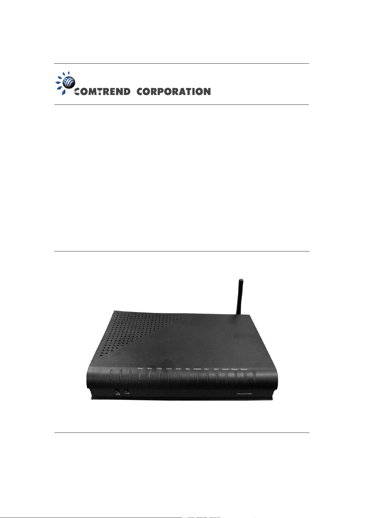
NexusLink 5700
Wireless ADSL bonding IAD
User’s Manual
Version C1.0, October 5, 2010
260101-001
Page 2

Warning
Before servicing or disassembling this equipment, always disconnect all
power and telephone lines from the device.
Use an appropriate power supply and a UL Listed telephone line cord.
Specification of the power supply is clearly stated in Appendix C.
Preface
This manual provides information to network administrators. It covers the
installation, operation and applications of the Wireless ADSL bonding IAD.
The individual reading this manual is presumed to have a basic understanding of
telecommunications.
This document is subject to change without notice. For product update, new
product release, manual revision, software upgrade, technical support, etc., visit
Comtrend Corporation at http://www.comtrend.com
FCC Interference Statement
This equipment has been tested and found to comply with the limits for a Class B
Digital Device, pursuant to part 15 of the FCC Rules. These limits are designed to
provide reasonable protection against harmful interference in a residential
installation. This equipment generates, uses and can radiate radio frequency
energy and, if not installed and used in accordance with the instruction, may
cause harmful interference to radio communication. However, there is no grantee
that interference will not occur in a particular installation. If this equipment dose
cause harmful interference to radio or television reception, which can be
determined by turning the equipment off and on , the user is encouraged to try to
correct the interference by one or more of the following measures:
Reorient or relocate the receiving antenna.
Increase the separation between the equipment and receiver.
Connect the equipment into an outlet on a circuit different from that to which
the receiver is connected
Consult the dealer or an experienced radio/TV technician for help
FCC Caution: The changes or modifications not expressly approved
by the party responsible for compliance could void the
user's authority to operate the equipment.
1
Page 3
This device complies with Part 15 of the FCC Rules. Operation is subject to the
following two conditions:
1. This device may not cause harmful interference
2. This device must accept any interference received, including interference that
may cause undesired operation.
FCC Radiation Exposure Statement
To comply with the FCC RF exposure compliance requirements, this device and its
antenna must not be co-located or operating to conjunction with any other
antenna or transmitter.
This equipment should be installed and operated with minimum distance
20cmbetween the radiator & your body
Copyright
Copyright© 2010 Comtrend Corporation. All rights reserved. The information
contained herein is proprietary to Comtrend Corporation. No part of this document
may be translated, transcribed, reproduced, in any form, or by any means without
the prior written consent of Comtrend Corporation.
Technical support
If you find the product to be inoperable or malfunctioning, please contact a technical
support engineer for immediate service by email at [email protected]
Save Our Environment
This symbol means that when the equipment has reached the end of its
useful life, it must be taken to a recycling centre and processed separate
from domestic waste.
The cardboard box, the plastic contained in the packaging, and the parts that make
up this device can be recycled in accordance with regionally established regulations.
Never throw-out this electronic equipment along with your household waste. You
may be subject to penalties or sanctions under the law. Instead, ask for
instructions from your municipal government on how to correctly dispose of it.
Please be responsible and protect our environment.
2
Page 4

Table of Contents
CHAPTER 1 INTRODUCTION .................................................................................................... 6
1.1 F
EATURES
1.2 A
PPLICATION
1.3 F
RONT PANEL
CHAPTER 2 INSTALLATION ...................................................................................................... 9
2.1 H
ARDWARE INSTALLATION
CHAPTER 3 LOGIN VIA WEB BROWSER ............................................................................. 10
3.1 IP A
3.2 L
OGIN PROCEDURE
CHAPTER 4 DEVICE ......................................................................................................................... 12
4.1 D
EVICE SUMMARY
4.2 R
ESET STATISTICS
4.3 T
ROUBLESHOOT
4.4 W
IRELESS
4.4.1 Enable Wireless............................................................................................................. 19
4.4.2 Wireless - Security Configure.................................................................................. 19
........................................................................................................................................ 6
................................................................................................................................... 7
LED I
NDICATORS
DDRESS
................................................................................................................................... 10
........................................................................................................................ 11
........................................................................................................................ 13
.......................................................................................................................... 14
............................................................................................................................ 15
...................................................................................................................................... 17
...................................................................................................... 8
.............................................................................................................. 9
4.4.3 WPS Setup ...................................................................................................................... 22
4.4.4 Wireless - Advanced Configure............................................................................... 26
4.5 R
ESTART YOUR SYSTEM
4.6 H
OME NETWORK
4.7 G
AMING AND APPLICATIONS
4.7.1 Incoming Traffic Control............................................................................................ 33
4.7.2 Outgoing Traffic Control ............................................................................................ 35
4.8 R
ESET ACCESS CODE
CHAPTER 5 BROADBAND ............................................................................................................... 39
5.1 S
TATUS
.......................................................................................................................................... 39
5.2 C
ONFIGURE
CHAPTER 6 HOME NETWORK ......................................................................................................42
6.1 LAN S
6.2 C
ONFIGURE
6.3 W
IRELESS STATUS
6.4 W
IRELESS CONFIGURE
................................................................................................................................... 40
TATUS
................................................................................................................................. 42
................................................................................................................................... 43
................................................................................................................ 28
........................................................................................................................... 30
.......................................................................................................... 32
.....................................................................................................................37
......................................................................................................................... 48
.................................................................................................................. 49
6.5 W
IRELESS
CHAPTER 7 VOIP...............................................................................................................................52
MAC F
ILTER
................................................................................................................ 50
3
Page 5

7.1
STATUS
.......................................................................................................................................... 53
7.2 SIP ................................................................................................................................................ 53
7.2.1 Global Parameters ....................................................................................................... 54
7.2.2 Service Provider............................................................................................................ 55
7.3 RTCP ............................................................................................................................................ 57
7.3.1 Global Parameters ................................................................................................................57
7.3.2 Service Provider .................................................................................................................... 58
7.4 T
ELEPHONE CALLS
CHAPTER 8 FIREWALL ................................................................................................................... 59
8.1 S
TATUS
.......................................................................................................................................... 61
8.2 I
NBOUND FILTER
8.3 O
UTBOUND FILTER
8.4 P
ORT FORWARDING
8.5 P
ORT TRIGGERING
CHAPTER 9 MAINTENANCE .......................................................................................................... 67
9.1 T
EST
.............................................................................................................................................. 67
9.2 DSL............................................................................................................................................... 68
........................................................................................................................ 59
........................................................................................................................... 61
........................................................................................................................ 61
........................................................................................................................ 62
......................................................................................................................... 65
9.2.1 xDSL BER Test .............................................................................................................. 69
9.2.2 Reset Statistics ............................................................................................................. 71
9.2.3 Draw Graph Tone ......................................................................................................... 71
9.2.4 Draw Loss of Signal Graph ....................................................................................... 72
9.2.5 Draw Loss of Frames Graph..................................................................................... 72
9.2.6 Loss of Power................................................................................................................. 73
9.3 P
ING/TRACEROUTE
9.3.1 Ping....................................................................................................................................74
9.3.2 TraceRoot ........................................................................................................................75
9.3.3 NSLookup ........................................................................................................................ 75
9.4 S
YSTEM LOG
9.4.1 Refresh............................................................................................................................. 77
9.4.2 Export Syslog................................................................................................................. 77
9.5 P
ASSWORD
9.5.1 Use New Access Code................................................................................................. 80
9.5.2 Clear Input...................................................................................................................... 80
9.5.3 Reset to Default Access Code.................................................................................. 80
..................................................................................................................................... 79
/NSL
OOKUP
.................................................................................................... 74
................................................................................................................................. 76
9.6 U
PGRADE
9.7 R
EBOOT
9.8 F
ACTORY RESET
....................................................................................................................................... 81
......................................................................................................................................... 82
............................................................................................................................ 83
4
Page 6

APPENDIX A: FIREWALL ................................................................................................................ 85
APPENDIX B: PIN ASSIGNMENTS ................................................................................................. 89
APPENDIX C: SPECIFICATIONS.................................................................................................... 90
APPENDIX D: SSH CLIENT ............................................................................................................. 93
5
Page 7

Chapter 1 Introduction
The NexusLink 5700 Wireless ADSL bonding IAD features flexible networking
connectivity with dual ADSL line capability, four 10/100 Ethernet ports, and an
802.11g wireless LAN access point. It has robust routing capabilities to segment
and direct data streams and allows for multiple data encapsulations.
The NexusLink 5700 is a black box solution for deploying Triple Play architectures,
doubling bandwidth (48Mbps) performance over traditional ADSL2 modems. It
provides higher level performance with embedded security, QoS, VPN and remote
management functions. As an added bonus, the USB host acts as a printer hub and
will enable future product enhancements available by software upgrade.
1.1 Features
• NexusLink 5700 (Annex M)
• Dual ADSL2 PTM bonded
• Wi-Fi Support
• UPnP installation
• Integrated 802.11b/g/n
• WPA and 802.1x
• RADIUS client
• IP /MAC address filtering
• Static route/RIP/RIP v2 routing functions
• Dynamic IP assignment
• NAT/PAT
• IGMP Proxy and fast leave
• DHCP Server/Relay/Client
• DNS Relay
• Supports 16 VCs
• Embedded SNMP agent
• Web-based management
• Remote configuration and upgrade
• Supports TR-069/TR-098/TR-104/TR-111 For Remote Management
• Configuration backup and restoration
• FTP server
• TFTP server
6
Page 8
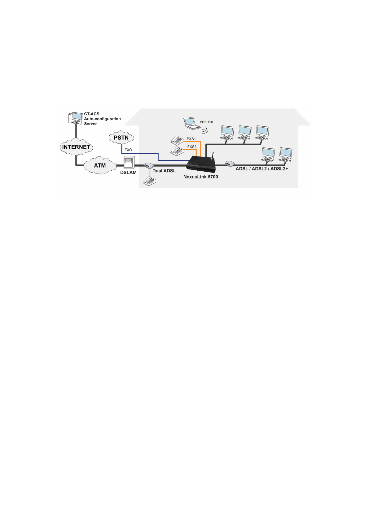
1.2 Application
This diagram depicts the application of the NexusLink 5700 on a wireless network.
7
Page 9
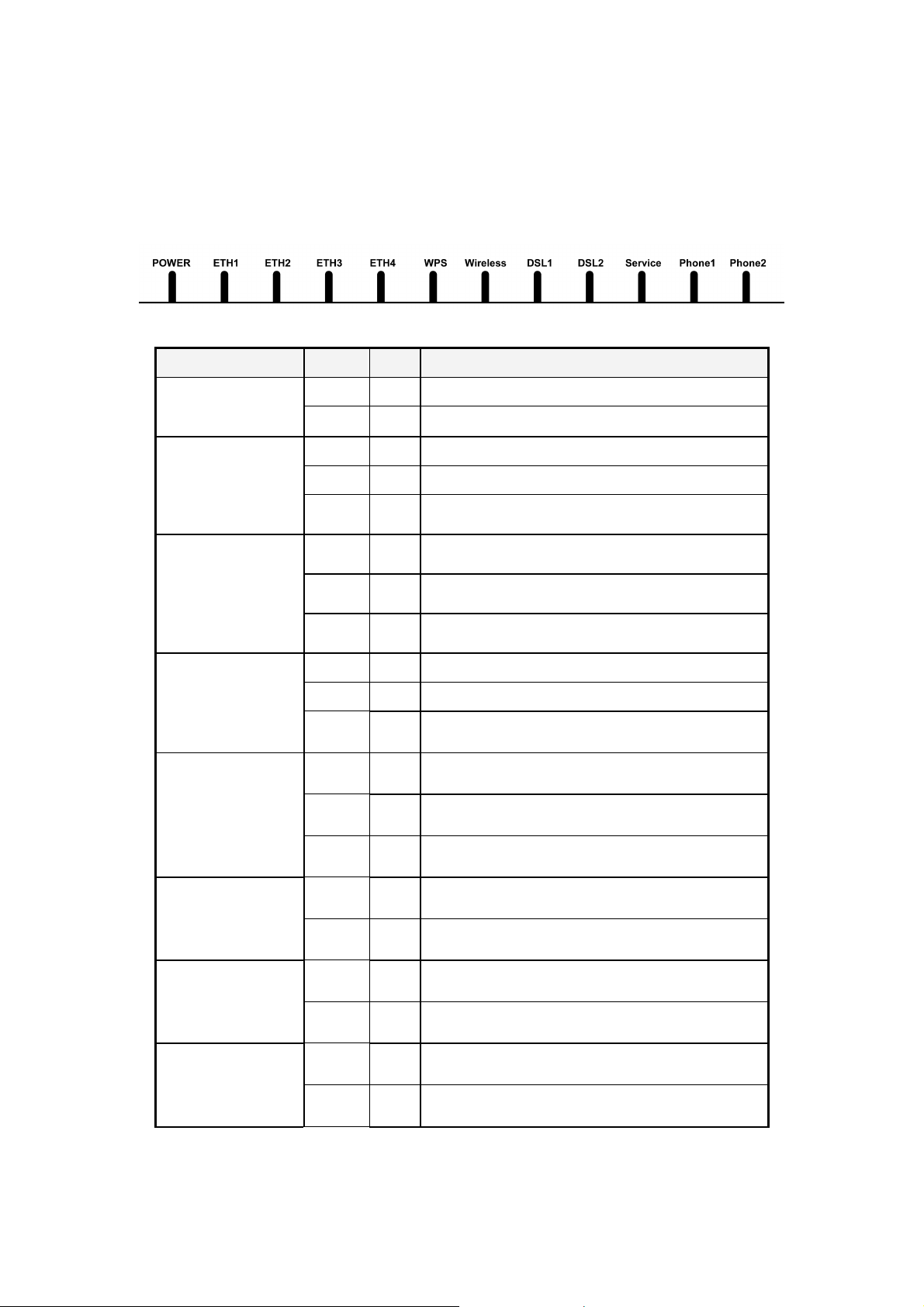
1.3 Front Panel LED Indicators
The front panel LED indicators are shown in the picture below, followed by an
explanation in the table below.
LED Color Mode Function
Green On The router is powered up. POWER
Off The router is powered down.
Green On An Ethernet Link is established.
LAN 1X~4X
WPS
WIRELESS
DSL1~DSL2
Service
Off An Ethernet Link is not established.
Green Blink Data transmitting or receiving over LAN.
Green On WPS mode exists protected clients
Blink WPS mode is on for 120 seconds
Green Off WPS mode is off
Green On The Wireless is ready and idle.
Off The Wireless is not installed.
Green Blink
Green
Off The DSL link is not established.
Green Blink The DSL link is training.
Green On The Internet link (PVC) is established.
Off The Internet link (PVC) is not established.
Data transmitting or receiving over Wireless
The DSL link is established.
Green
Phone1
Green On
Phone2
On The FXS phone 1 is off hook.
Off The FXS phone 1 is on hook.
The FXS phone 2 is off hook.
Off The FXS phone 2 is on hook.
8
Page 10
Chapter 2 Installation
erify that the
power supply is connected correctly. If the problem persists, contact
Before servicing or disassembling this equipment always disconnect all
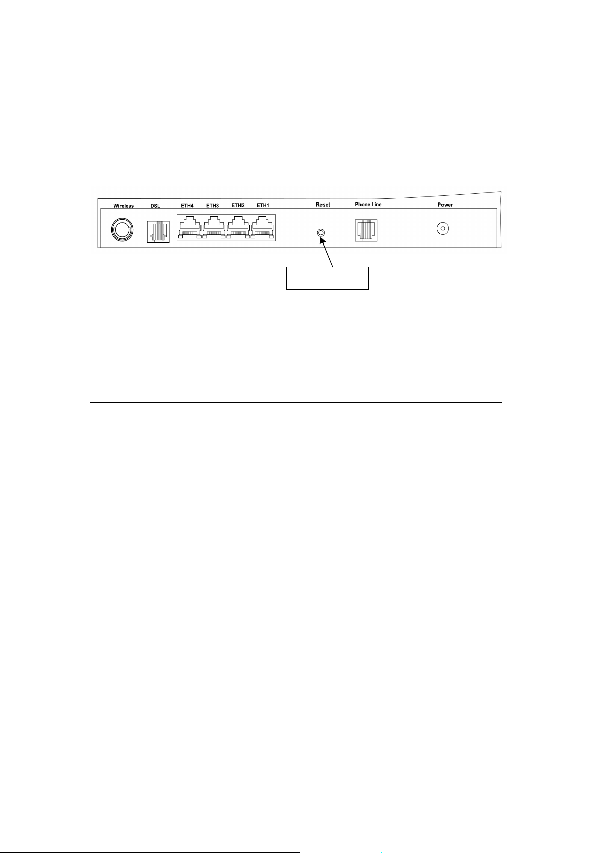
Reset button
2.1 Hardware Installation
Follow the instructions below to complete the hardware installation.
A schematic of the back of the router is shown below for reference.
Connection to Power
Connect the power jack to the shipped power cord. Attach the power adapter to
the wall outlet or other AC source. After all connections have been made the router
will perform a self-test. Wait a few moments and the router will be ready to
operate.
Caution 1: If the router fails to power up, or if it malfunctions, first v
our technical support engineers.
Caution 2:
power cords and telephone lines from the wall outlet.
Connection to LINE port
Connect the telephone set to the RJ14 Phone1/ Phone2 port for VoIP service.
Reset Button
In the rear panel, there is a reset button. To load the factory default settings, hold
the reset button down for 5 to 10 seconds.
Connection to ETH port
To connect to a hub or PC, use a RJ45 cable. You can connect the router to up to four
LAN devices. The ports are auto-sensing MDI/X and either straight-through cable
or crossover cable can be used.
DSL
Connect to the ADSL port with the ADSL RJ14 cable.
9
Page 11
Chapter 3 Login via Web Browser
This section describes how to manage the router via a web browser. The web page
is best viewed with Microsoft Internet Explorer 5.0 and later. Access Code Required:
#0009@3BFA. The user can change the Access Code later (see 9.5 Password).
3.1 IP Address
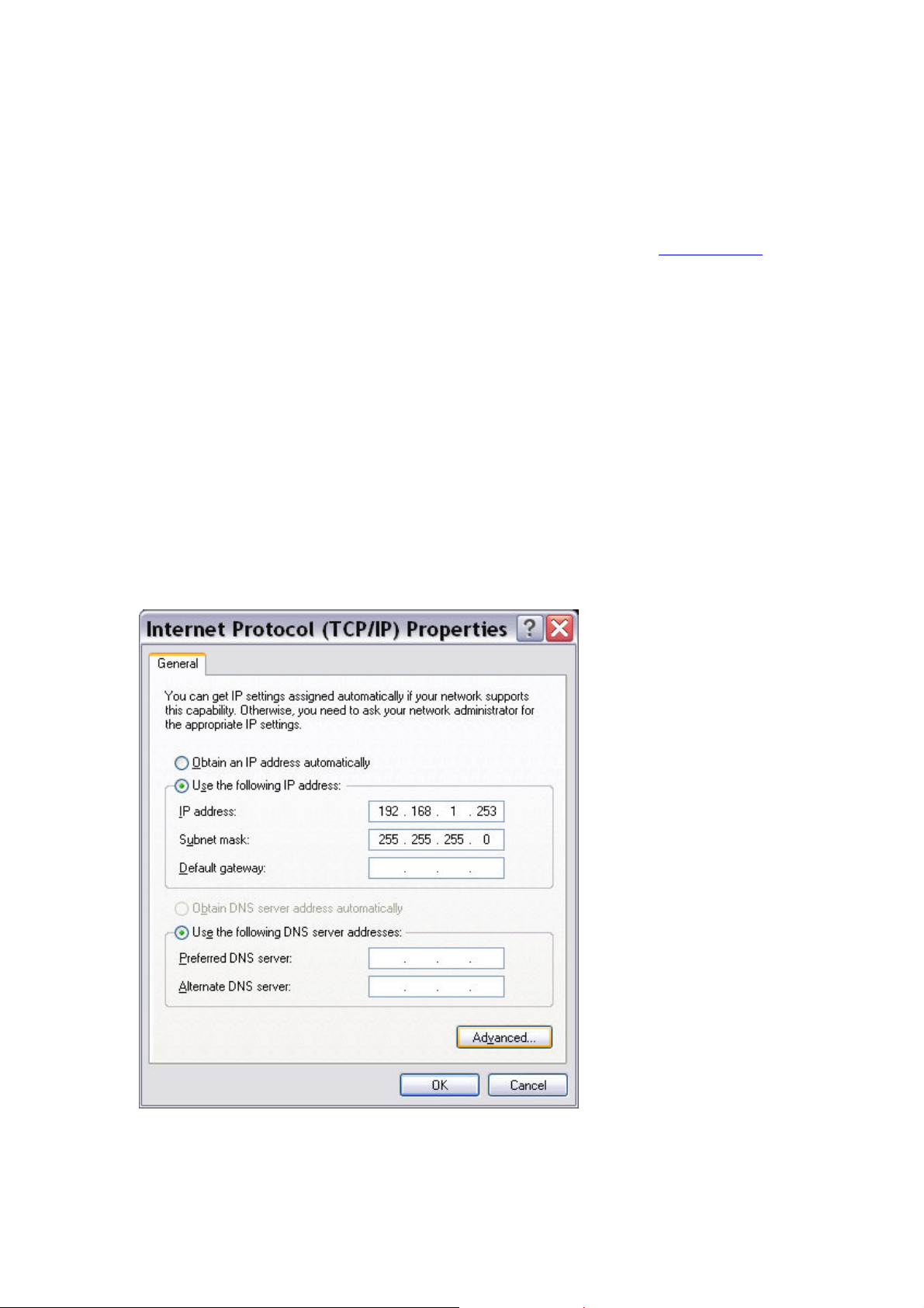
The default IP address of the router (LAN port) is 192.168.1.254 To configure the
router for the first time, the configuration PC must have a static IP address within
the 192.168.1.x subnet. Follow the steps below to configure your PC IP address to
use subnet 192.168.1.x.
STEP 1: Right click on the Local Area Connection under the Network and Dial-Up
connection window and select Properties.
STEP 2: Enter the TCP/IP window and change the IP address to 192.168.1.x/24.
STEP 3: Click OK to submit settings.
10
Page 12

3.2 Login Procedure
Perform the following steps to bring up the web browser and configure the router.
STEP 1: Start the Internet browser. Type the IP address for the router in the Web
address field. For example, if the IP address is 192.168.1.254, type
http://192.168.1.254
11
Page 13
Chapter 4 Device
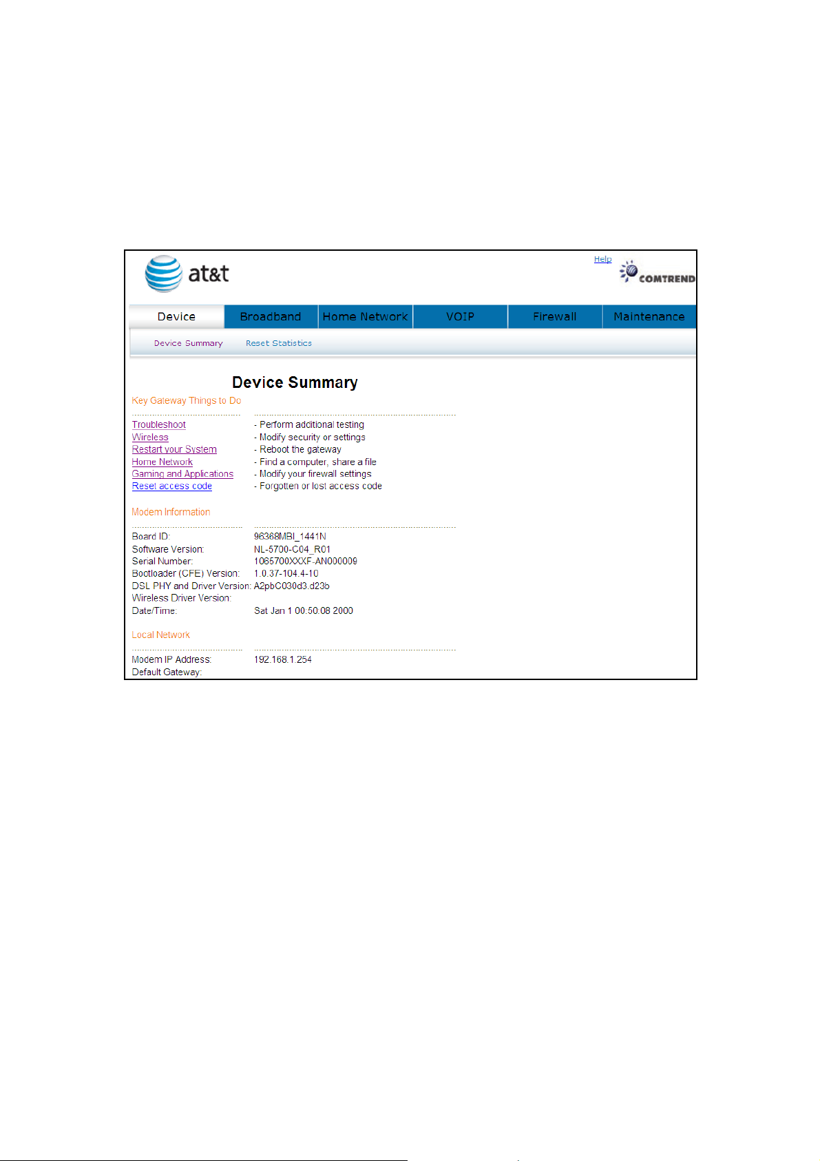
Select the Device button from the main menu to display the Device Summary
information as here.
12
Page 14
4.1 Device Summary
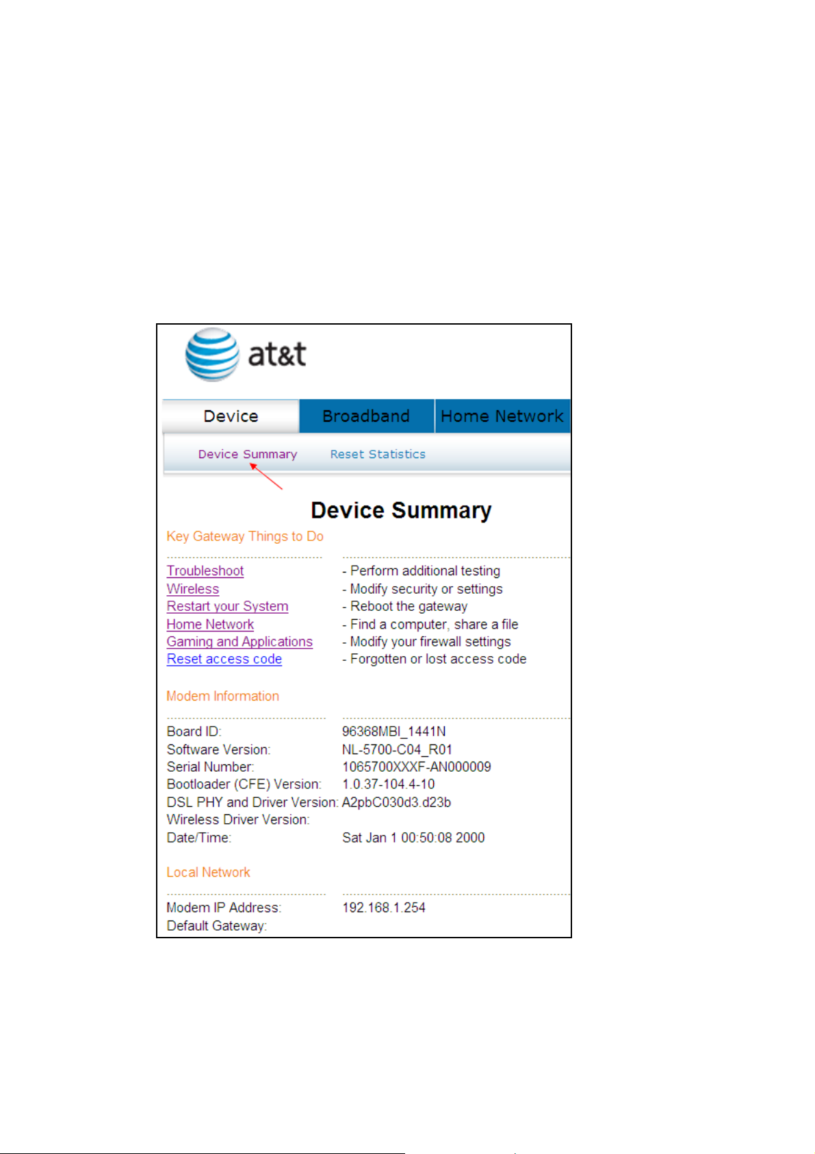
The main menu has several options, and selecting each of these options opens a
submenu with more selections.
Subsequent sections will introduce the other main menu options in sequence.
The Device Summary screen will display at startup.
13
Page 15
4.2 Reset Statistics
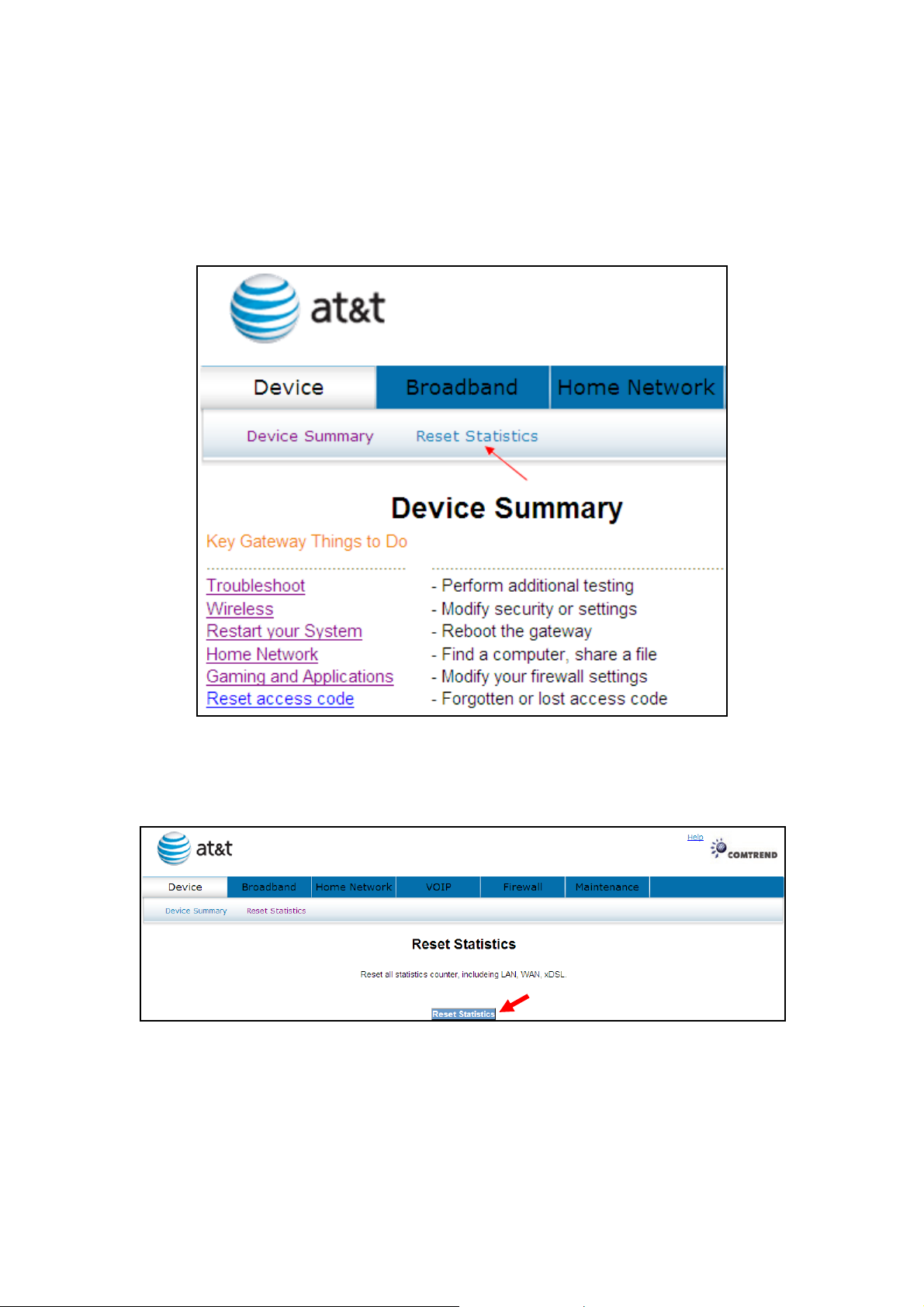
To reset all statistics including LAN, WAN and xDSL click Reset Statistics.
When the following window is displayed, simply click the Reset Statistics button to
confirm your choice.
14
Page 16
4.3 Troubleshoot
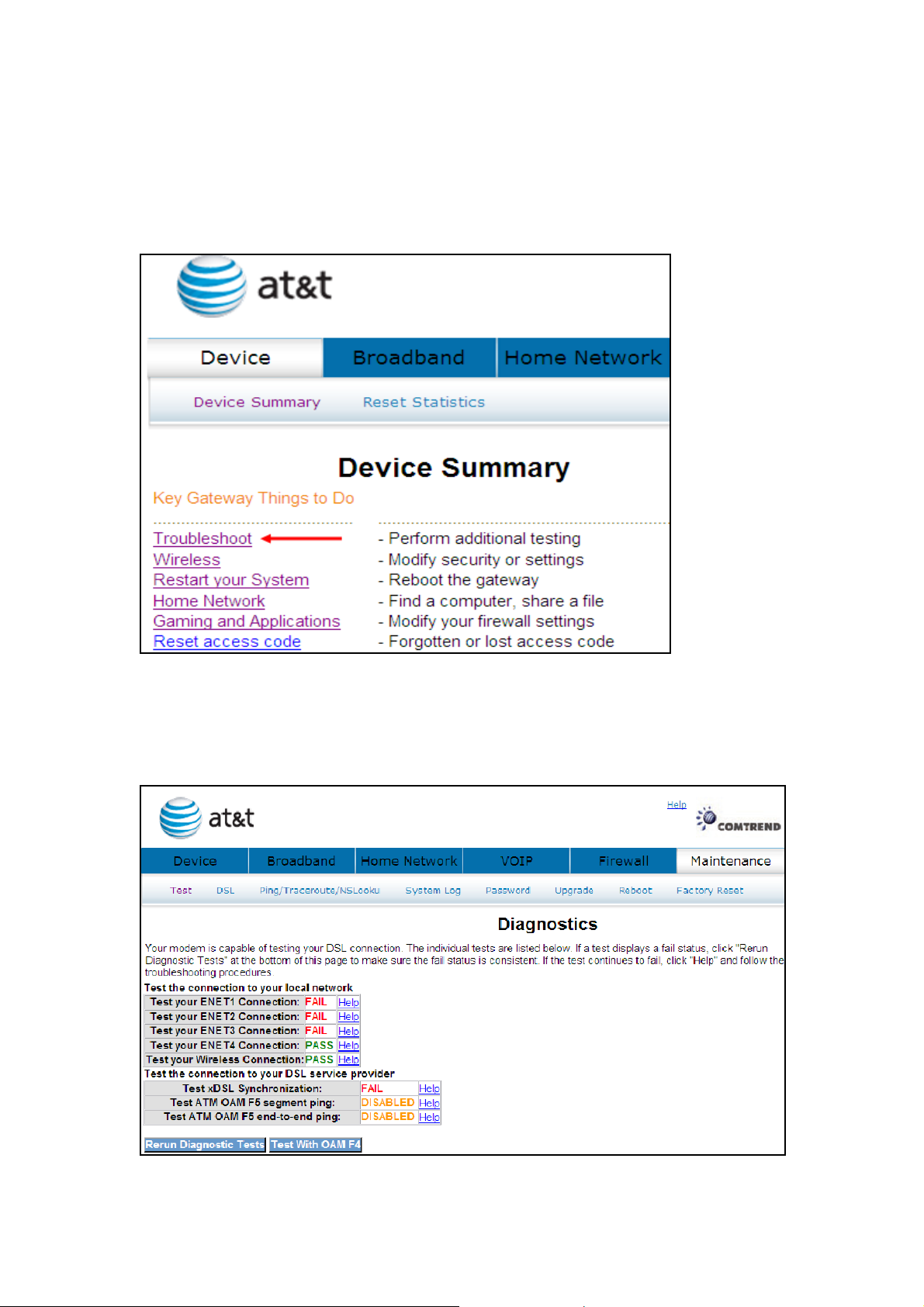
Your device is capable of testing your DSL connection. Click Troubleshoot and the
diagnostics window will display.
The Diagnostics menu provides feedback on the connection status of the device
and the ADSL link. Click Troubleshoot to bring up the following window.
The individual test results are explained below.
15
Page 17
Test Description
computer is connected to the LAN port of your DSL router. A
signal from the telephone company. A solid WAN LED on the
indicates that the DSL modem does not detect a signal
from the telephone company’s DSL network. The WAN LED
Ethernet Connection Pass: indicates that the Ethernet interface from your
flashing or solid green LAN LED on the router also signifies
that an Ethernet connection is present and that this test is
successful.
Fail: Indicates that the DSL router does not detect the
Ethernet interface on your computer.
Wireless Connection Pass: Indicates that the Wireless interface from your
computer is connected to the wireless network.
Down: Indicates that the DSL router does not detect the
wireless network.
DSL Synchronization Pass: Indicates that the DSL modem has detected a DSL
router also indicates the detection of a DSL signal from the
telephone company.
Fail:
will continue to flash green.
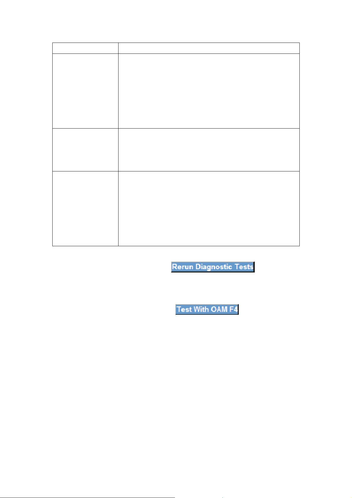
If a test displays a fail status, click the button at the
bottom of this page to make sure the fail status is consistent. If the test continues
to fail, click Help and follow the troubleshooting procedures. To test the connection
with your DSL service provider, click the button.
16
Page 18
4.4 Wireless
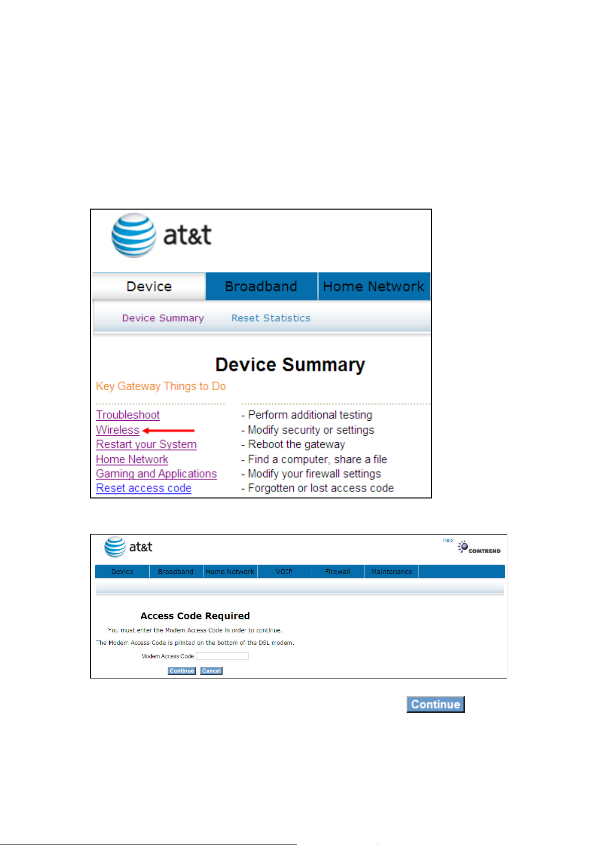
This page allows you to configure basic features of the wireless LAN interface. You
can enable or disable the wireless LAN interface, hide the network from active scans,
set the wireless network name (also known as SSID) and restrict the channel set
based on country requirements.
Click Wireless to bring up the following window.
Input the access code (which is located ______) and click the button.
17
Page 19
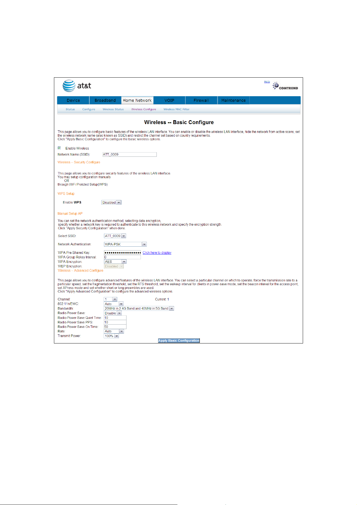
The options shown here allow you to configure security features of the wireless LAN
interface.
18
Page 20
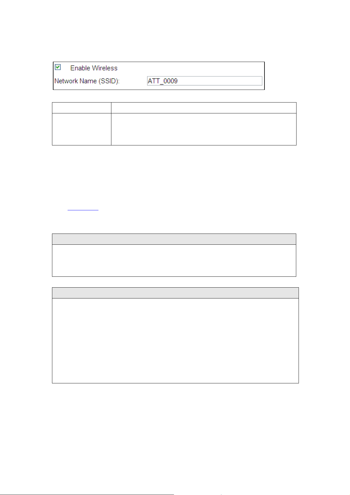
4.4.1 Enable Wireless
A checkbox that enables or disables the wireless LAN interface.
down box. SSID stands for Service
ct SSID to access the
This option specifies whether a network key is used for authentication to the wireless
ields. WEP
Option Description
Enable Wireless
When selected, the Web UI displays Hide Access point, SSID,
and County settings. The default is Enable Wireless.
4.4.2 Wireless - Security Configure
Wireless security settings can be configured according to Wi-Fi Protected Setup
(WPS) or Manual Setup. The WPS method configures security settings automatically
(see 4.4.3 WPS) while the Manual Setup method requires that the user configure
these settings using the Web User Interface (see the table below).
Select SSID
Select the wireless network name from the drop-
Set Identifier. All stations must be configured with the corre
WLAN. If the SSID does not match, that client will not be granted access.
Network Authentication
network. If network authentication is set to Open, then no authentication is
provided. Despite this, the identity of the client is still verified.
Each authentication type has its own settings. For example, selecting 802.1X
authentication will reveal the RADIUS Server IP address, Port and Key f
Encryption will also be enabled as shown below.
19
Page 21
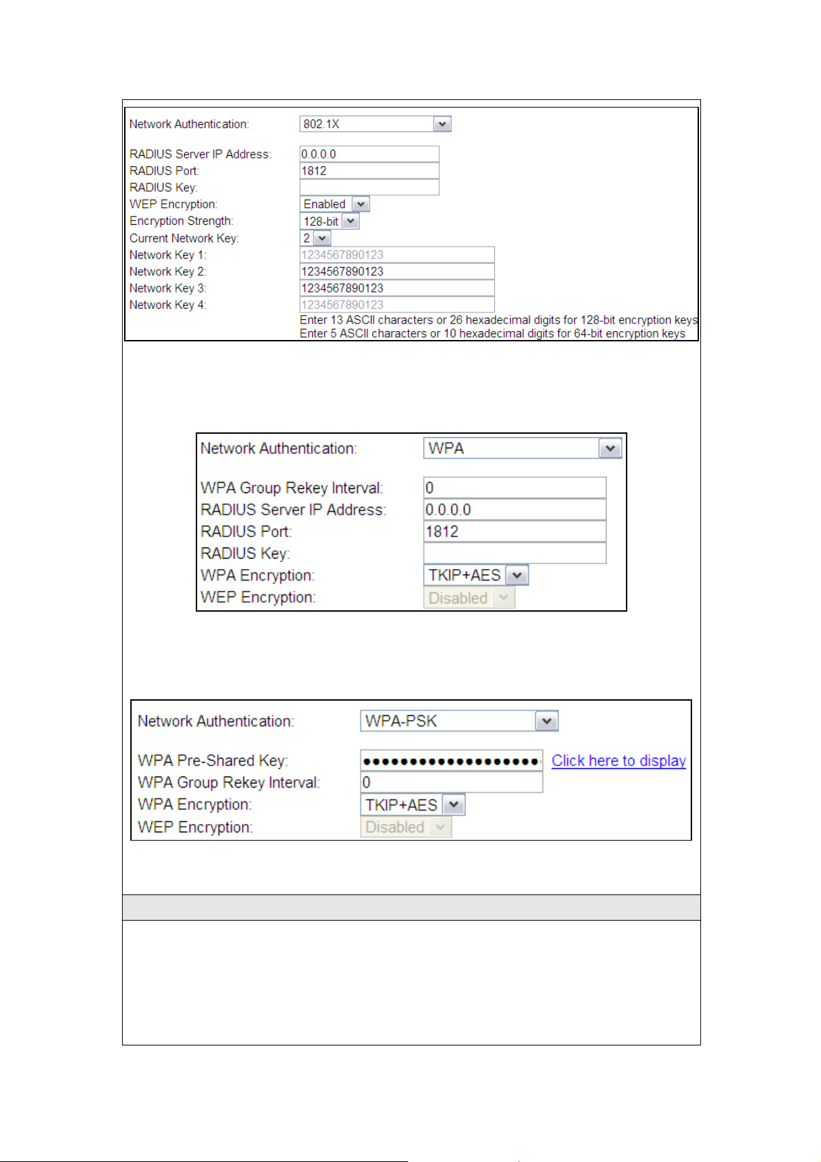
network key is used for data encryption and network authentication. Four network
keys can be defined although only one can be used at any one time. Use the Current
The settings for WPA authentication are shown below.
The settings for WPA-PSK authentication are shown next.
WEP Encryption
This option specifies whether data sent over the network is encrypted. The same
Network Key list box to select the appropriate network key.
20
Page 22

Security options include authentication and encryption services based on the wired
equivalent privacy (WEP) algorithm. WEP is a set of security services used to
ess, such as eavesdropping; in this
secret shared encryption keys are generated and used by the source station and the
Under shared key authentication, each wireless station is assumed to have received
means that keys with a greater number of bits have a greater degree of security and
protect 802.11 networks from unauthorized acc
case, the capture of wireless network traffic. When data encryption is enabled,
destination station to alter frame bits, thus avoiding disclosure to eavesdroppers.
a secret shared key over a secure channel that is independent from the 802.11
wireless network communications channel.
Encryption Strength
This drop-down list box will display when WEP Encryption is enabled. The key
strength is proportional to the number of binary bits comprising the key. This
are considerably more difficult to crack. Encryption strength can be set to either
64-bit or 128-bit. A 64-bit key is equivalent to 5 ASCII characters or 10
hexadecimal numbers. A 128-bit key contains 13 ASCII characters or 26
hexadecimal numbers. Each key contains a 24-bit header (an initiation vector)
which enables parallel decoding of multiple streams of encrypted data.
Current Network Key
Select the required network key.
21
Page 23
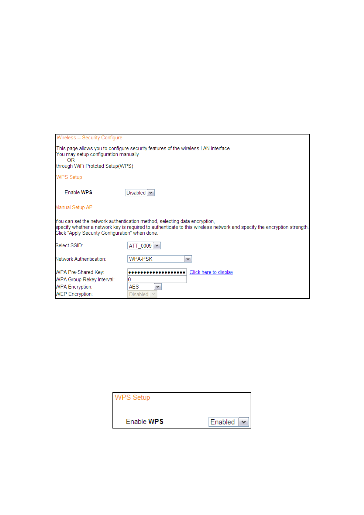
4.4.3 WPS Setup
Wi-Fi Protected Setup (WPS) is an industry standard that simplifies wireless security
setup for certified network devices. Every WPS certified device has both a PIN
number and a push button, located on the device or accessed through device
software. The NexusLink 5700 has both a WPS button on the device and a virtual
button accessible from the web user interface (WUI).
To configure security settings with WPS, follow the procedures below. You must
choose either the Push-Button or PIN configuration method for Steps 6 and 7.
I. Setup
Step 1: Enable WPS by selecting Enabled from the drop down list box shown.
22
Page 24
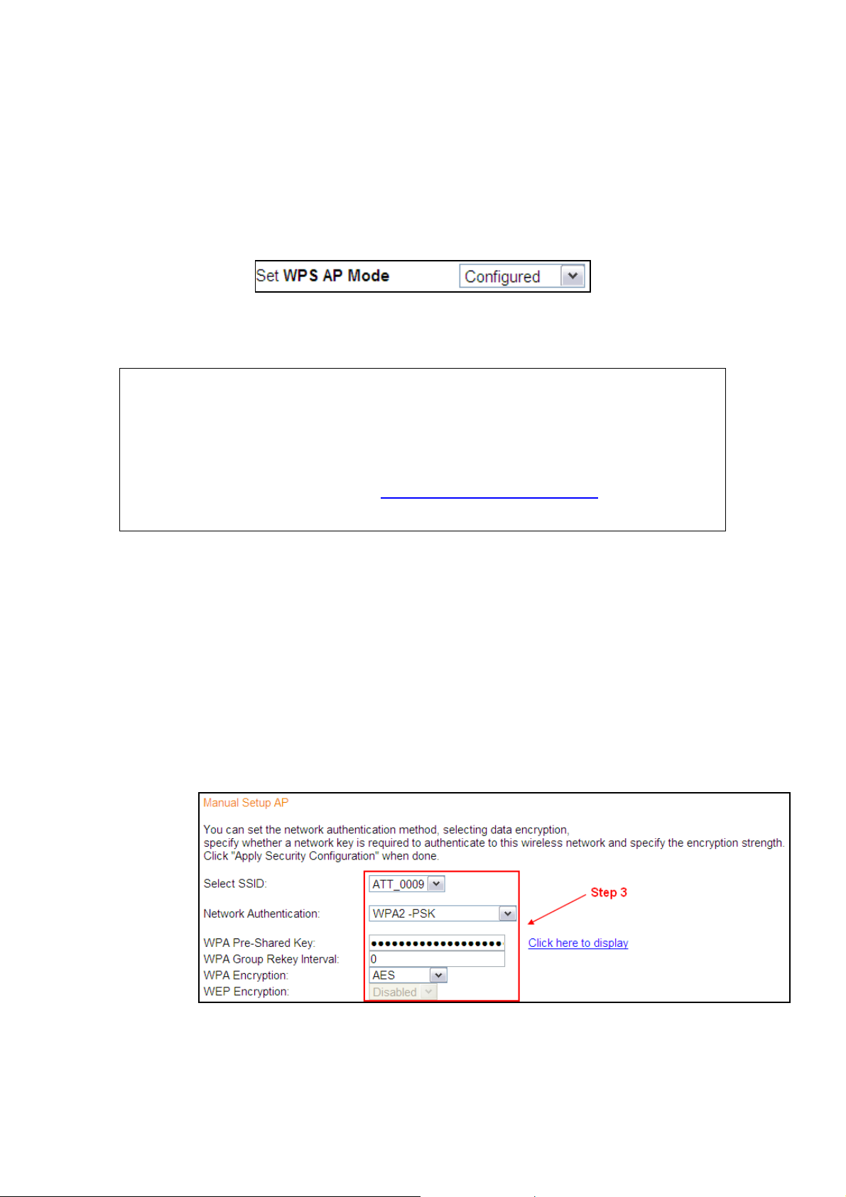
Step 2: Set the WPS AP Mode. Configured is used when the NexusLink 5700.
will assign security settings to clients. Unconfigured is used when an external
client assigns security settings to the NexusLink 5700.
NOTES: Your client may or may not have the ability to provide security settings to
the NexusLink 5700. If it does not, then you must set the WPS AP mode to
Configured. Consult the device documentation to check its capabilities.
In addition, using Windows Vista, you can add an external registrar using
the StartAddER button (Appendix E - WPS OPERATION has detailed
instructions).
II. NETWORK AUTHENTICATION
Step 3: Select Open, WPA-PSK, WPA2-PSK, or Mixed WPA2/WPA-PSK network
authentication mode from the Manual Setup AP section of the Wireless
Security screen. The example below shows WPA2-PSK mode.
Step 4: For the Pre-Shared Key (PSK) modes, enter a WPA Pre-Shared Key. You
23
Page 25
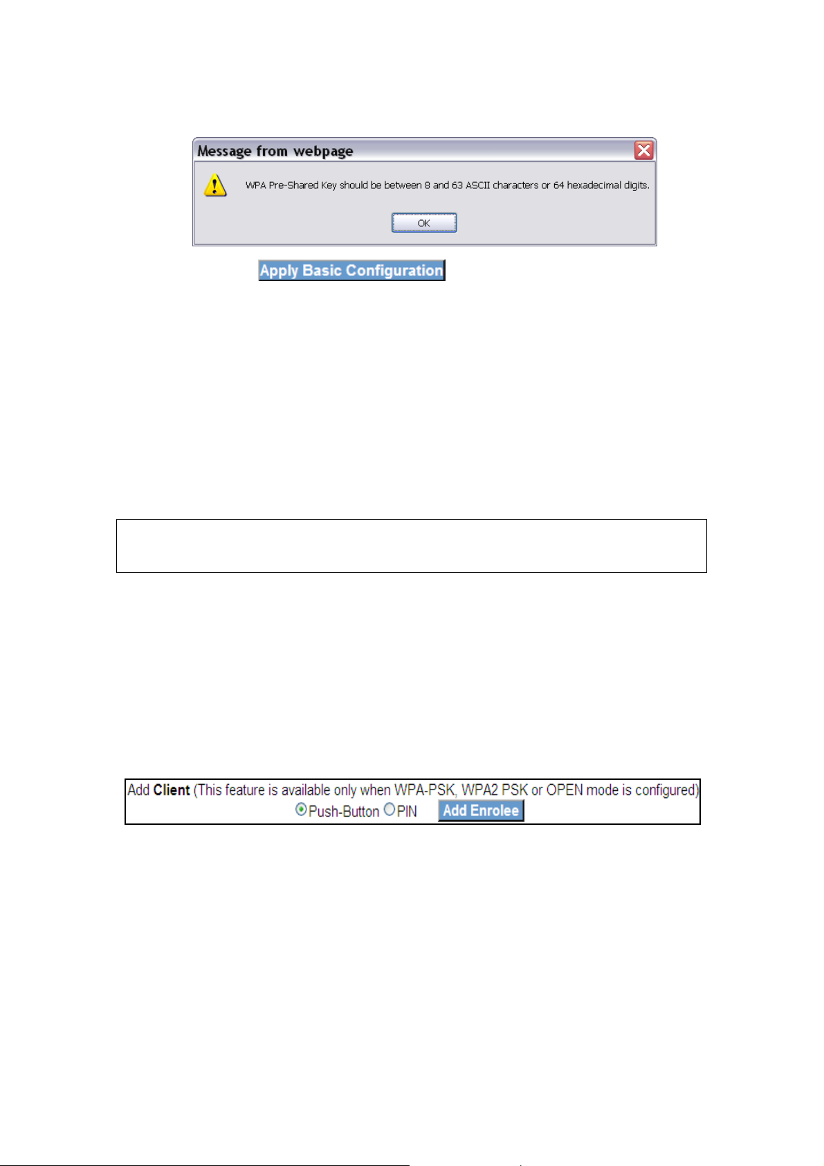
will see the following dialog box if the Key is too short or too long.
Step 5: Click the button at the bottom of the window.
IIIa. PUSH-BUTTON CONFIGURATION
The WPS push-button configuration provides a virtual button (accessible from the
web user interface) configuration method.
The WPS push-button configuration is described in the procedure below. It is
assumed that the Wireless function is Enabled and that the router is configured as
the Wireless Access Point (AP) of your WLAN. In addition, the wireless client must
also be configured correctly and turned on, with WPS function enabled.
NOTE: The wireless AP on the router searches for 2 minutes. If the router stops
searching before you complete Step 7, return to Step 6.
Step 6: WUI virtual button
Select the Push-Button radio button in the WPS Setup section of the
Wireless Security screen, and then click the appropriate button based on
the WPS AP mode selected in step 2.
For Configured mode, click the Add Enrollee button.
Step 7: Go to your WPS wireless client and activate the push-button function on
your NexusLink 5700.
A typical WPS client screenshot is shown below as an example.
24
Page 26
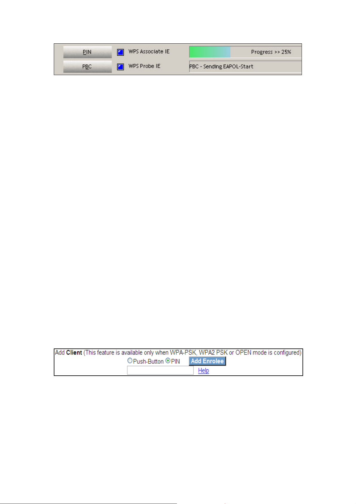
Now go to Step 8 (part IV. Check Connection) to check the WPS connection.
IIIb. WPS – PIN CONFIGURATION
Using this method, security settings are configured with a personal identification
number (PIN). The PIN can be found on the device itself or within the software.
The PIN may be generated randomly in the latter case. To obtain a PIN number for
your client, check the device documentation for specific instructions.
The WPS PIN configuration is described in the procedure below. It is assumed that
the Wireless function is Enabled and that the router is configured as the Wireless
Access Point (AP) of your wireless LAN. In addition, the wireless client must also be
configured correctly and turned on, with WPS function enabled.
Step 6: Select the PIN radio button in the WPS Setup section of the Wireless
Security screen, as shown in A or B below, and then click the appropriate
button based on the WPS AP mode selected in step 2.
A - For Configured mode, enter the client PIN in the box provided and
then click the Add Enrollee button (see below).
B - For Unconfigured mode, click the Config AP button.
25
Page 27
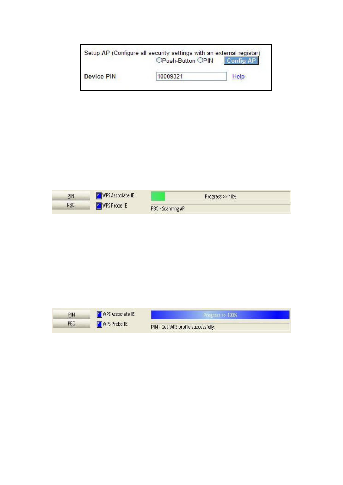
Step 7: Activate the PIN function on the wireless client. For Configured mode,
the client must be configured as an Enrollee. For Unconfigured mode,
the client must be configured as the Registrar. This is different from the
External Registrar function provided in Windows Vista.
The figure below provides an example of a WPS client PIN function in-progress.
Now go to Step 8 (part IV. Check Connection) to check the WPS connection.
IV. CHECK CONNECTION
Step 8: If the WPS setup method was successful, you will be able access the
wireless AP from the client. The client software should show the status.
The example below shows that the connection established successfully.
You can also double-click the Wireless Network Connection icon from the
Network Connections window (or the system tray) to confirm the status of
the new connection.
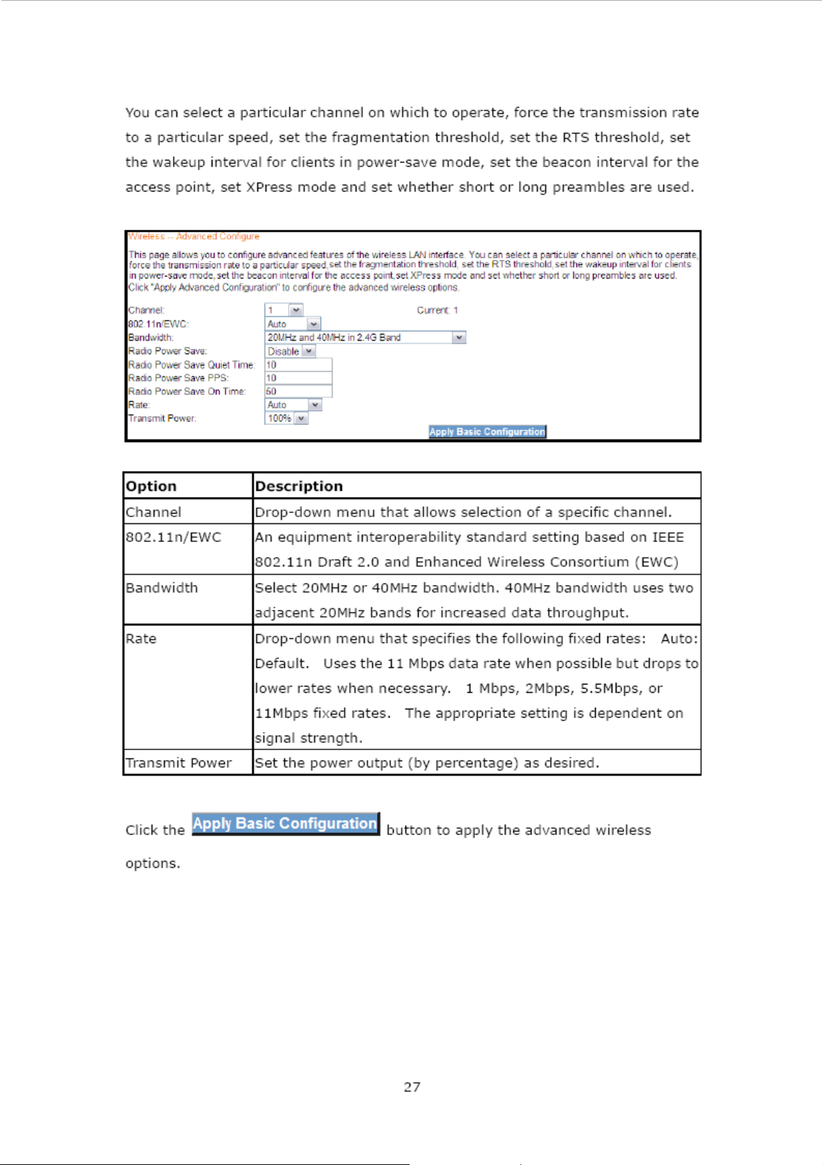
4.4.4 Wireless - Advanced Configure
The Advanced page allows you to configure advanced features of the wireless LAN
interface.
26
Page 28
Page 29

4.5 Restart Your System
Should you want to reboot the NexusLink 5700, please follow the instructions
provided below.
28
Page 30
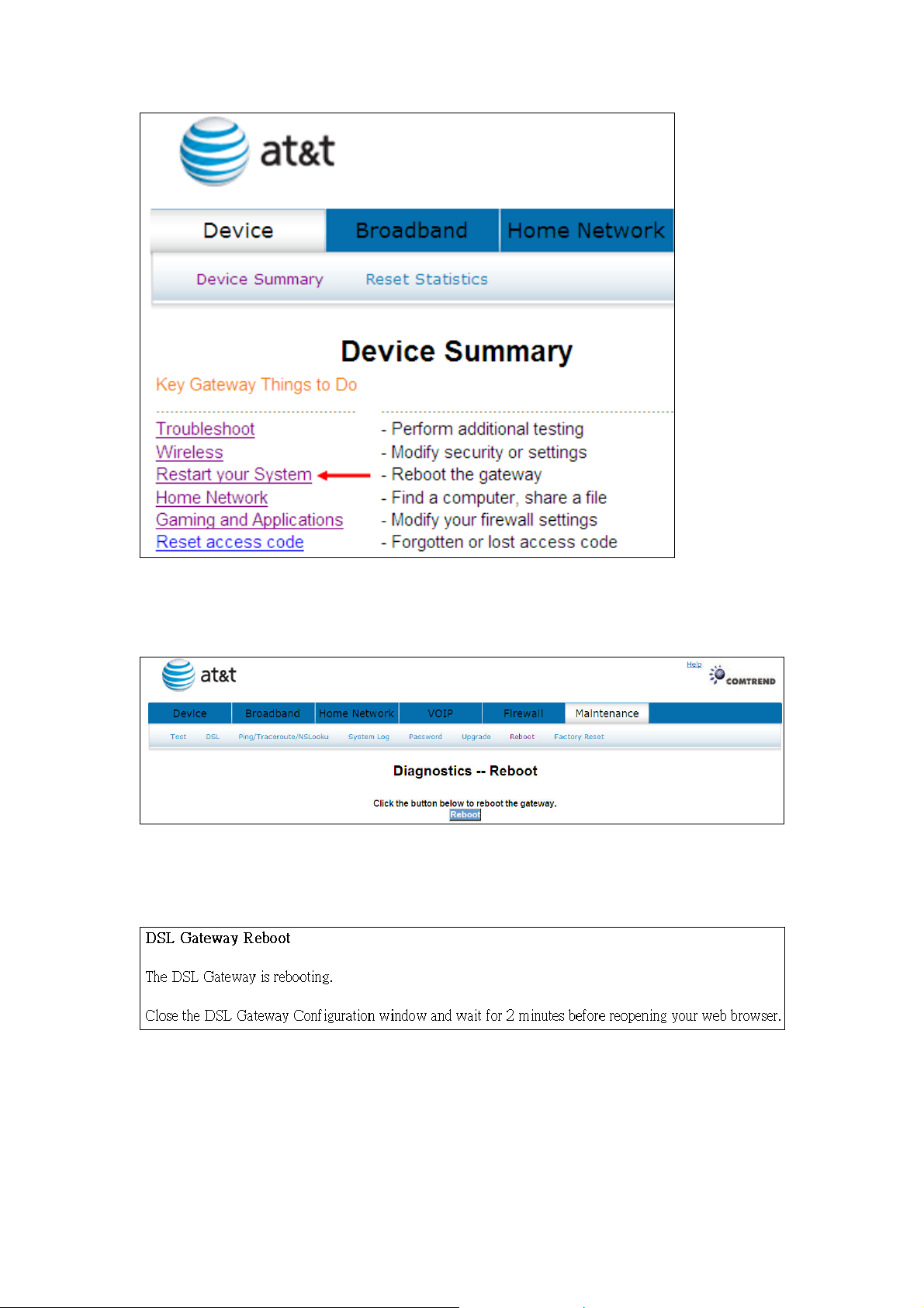
Click Restart your System to bring up the following window.
When the following window is displayed, simply click the Reboot button to confirm
your choice. The following window will display.
29
Page 31
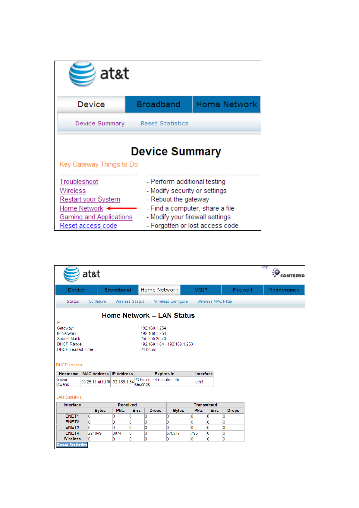
4.6 Home Network
Click Home Network to bring up the following window.
30
Page 32

Heading Description
Interface LAN interface(s)
Received/Transmitted: - Bytes
- Pkts
- Errs
- Drops
Click the button to refresh this screen.
Number of Bytes
Number of Packets
Number of packets with errors
Number of dropped packets
31
Page 33
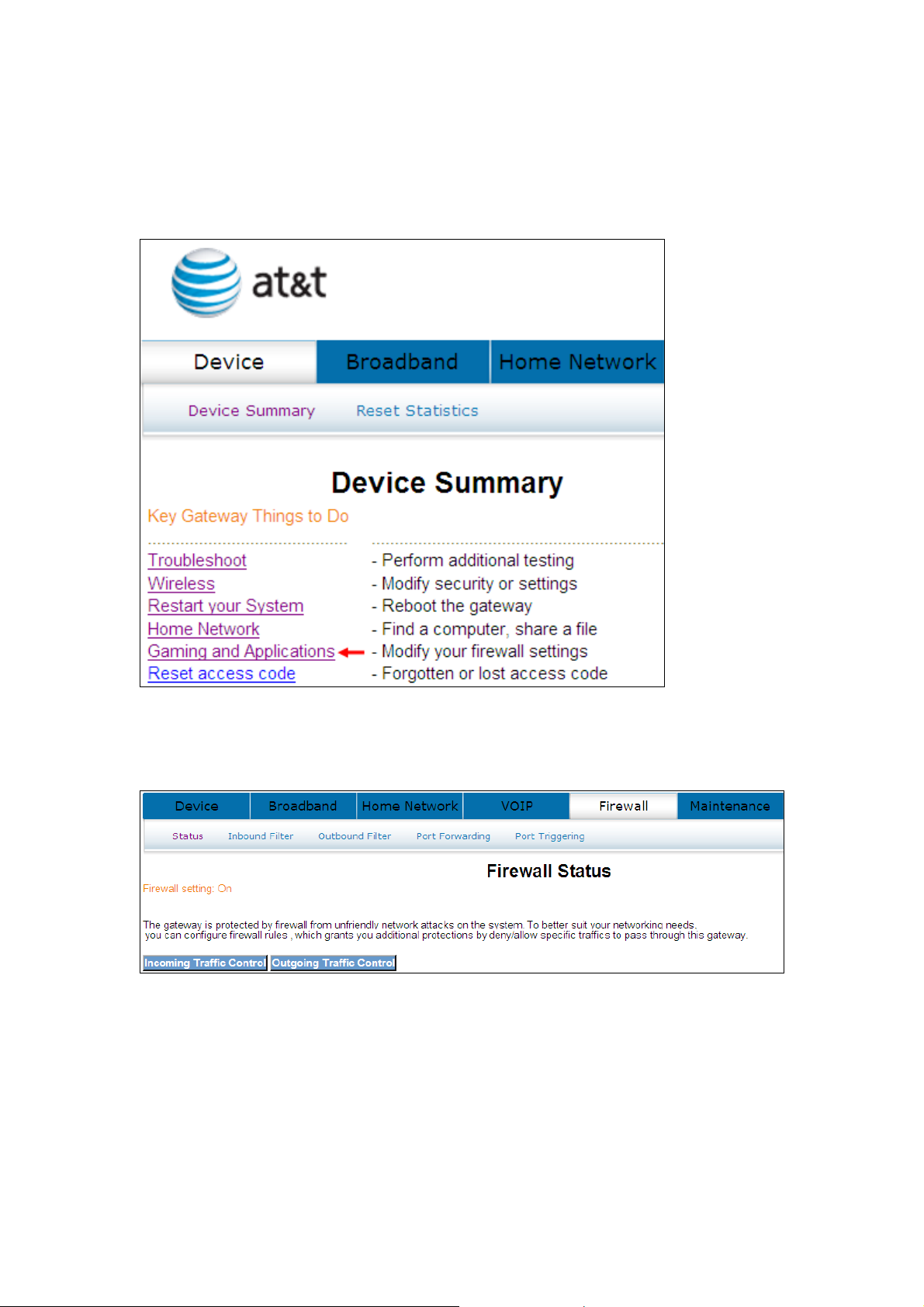
4.7 Gaming and Applications
This window allows you to modify your firewall settings.
Click Gaming and Applications to bring up the following window.
32
Page 34
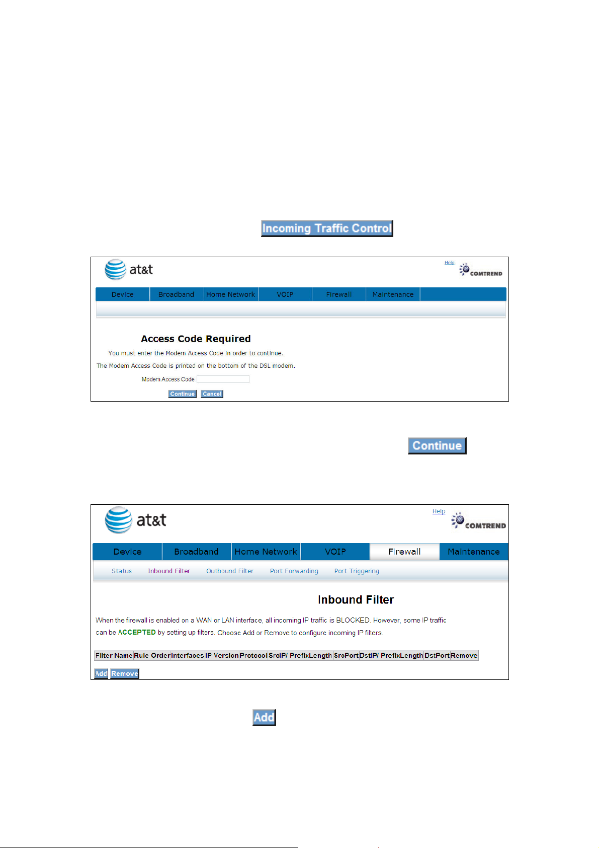
4.7.1 Incoming Traffic Control
IP filtering allows you to create a filter rule to identify outgoing/incoming IP traffic
by specifying a new filter name and at least one condition below. All of the specified
conditions in this filter rule must be satisfied for the rule to take effect.
The default setting for all Incoming traffic is Blocked.
To add or remove IP filters, Click
Input the access code (which is located ______) and click the button.
The options are shown (on the following page)
To add a filtering rule, click the button. The following window will be
displayed.
33
Page 35
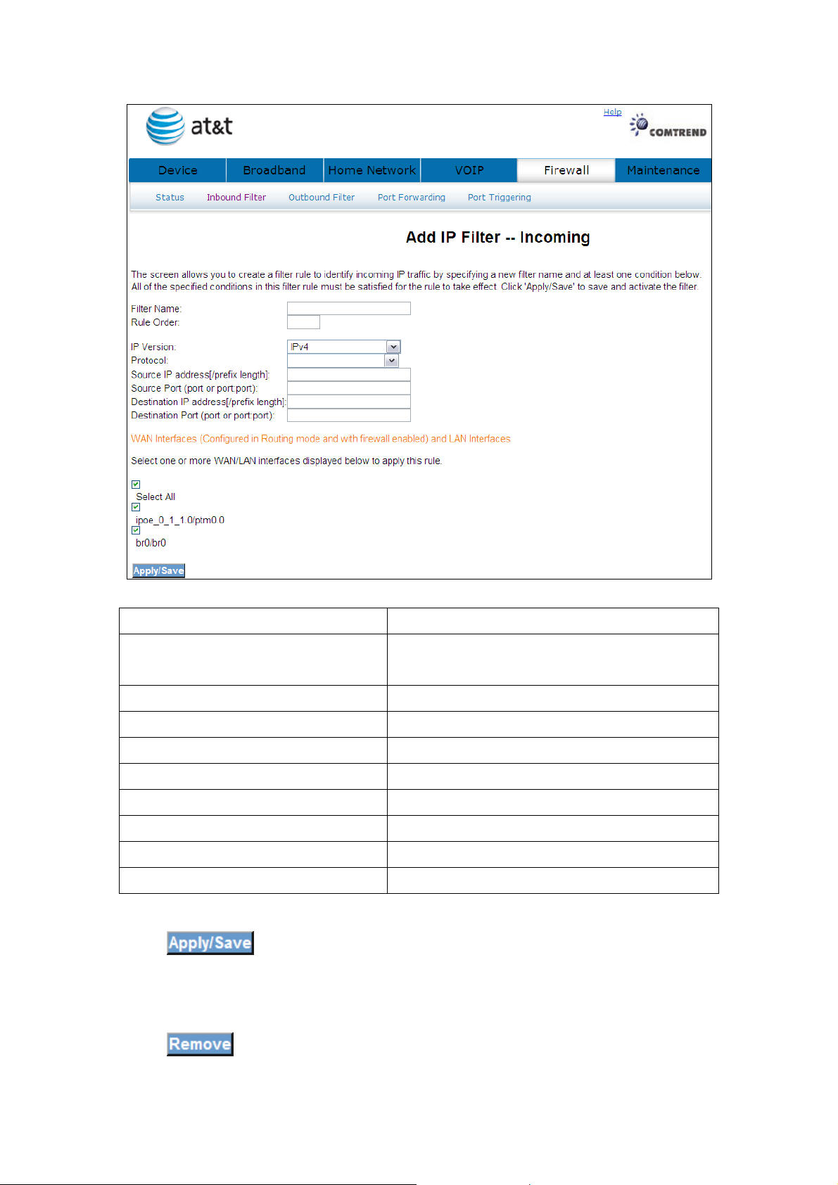
Filter Name Type a name for the filter rule.
Rule Order Execute IP Filter order. (Available in future
versions).
IP Version IPv4 selected by default.
Protocol User can select: TCP, TCP/UDP, UDP or ICMP.
Source IP address Input source IP address.
Source Subnet Mask Input source subnet mask.
Source Port (port or port:port) Input source port number.
Destination IP address Input destination IP address.
Destination Subnet Mask Input destination subnet mask.
Destination port (port or port:port) Input destination port number.
Click to save and activate the filter.
Click
to delete a filter.
34
Page 36
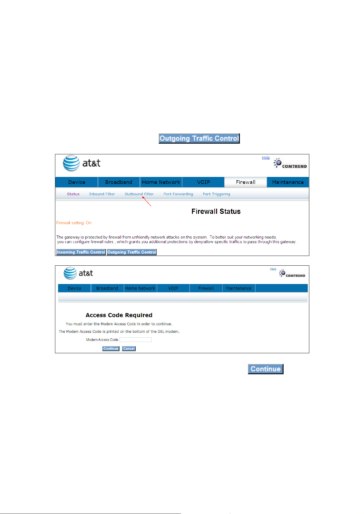
4.7.2 Outgoing Traffic Control
IP filtering allows you to create a filter rule to identify outgoing/incoming IP traffic
by specifying a new filter name and at least one condition below. All of the specified
conditions in this filter rule must be satisfied for the rule to take effect.
The default setting for all Outgoing traffic is Accepted.
To add or remove IP filters, Click
Input the access code (which is located ______) and click the button.
The options are shown (on the following page)
35
Page 37
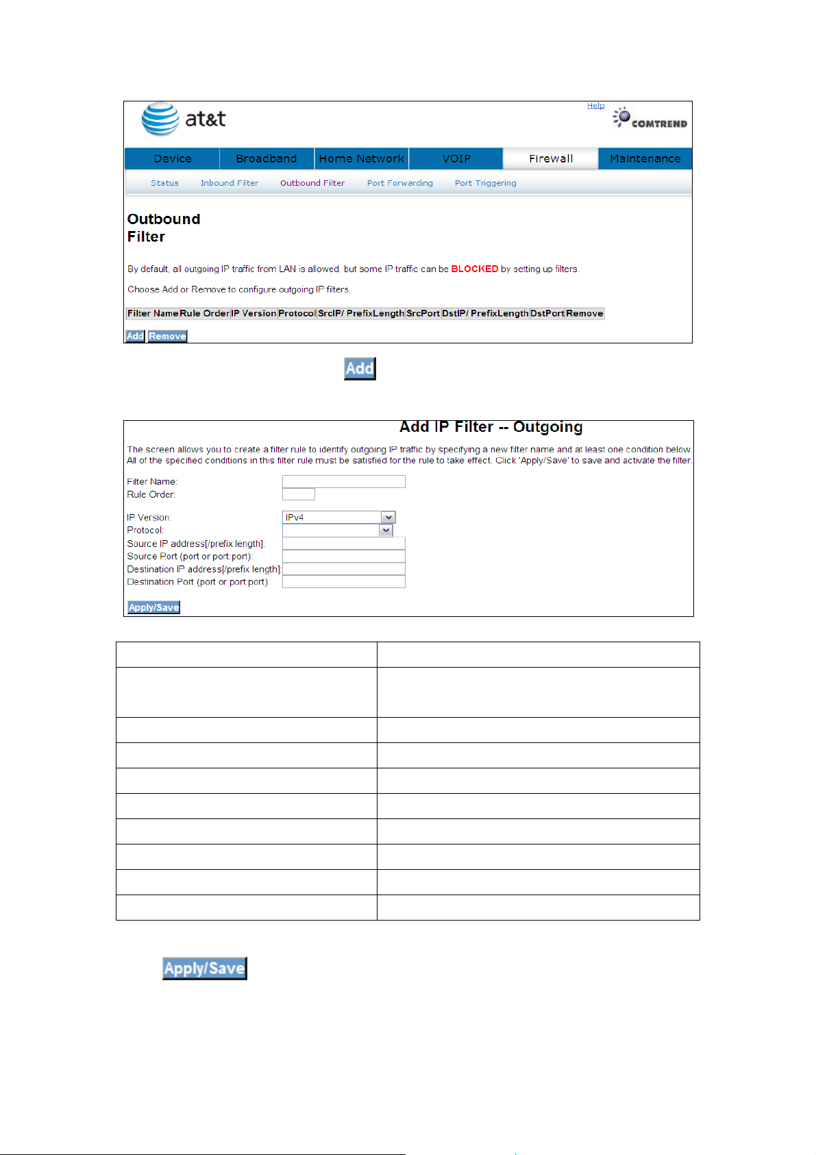
To add a filtering rule, click the button. The following window will be
displayed.
Filter Name Type a name for the filter rule.
Rule Order Execute IP Filter order. (Available in future
versions).
IP Version IPv4 selected by default.
Protocol User can select: TCP, TCP/UDP, UDP or ICMP.
Source IP address Input source IP address.
Source Subnet Mask Input source subnet mask.
Source Port (port or port:port) Input source port number.
Destination IP address Input destination IP address.
Destination Subnet Mask Input destination subnet mask.
Destination port (port or port:port) Input destination port number.
Click to save and activate the filter.
36
Page 38
Click
to delete a filter.
4.8 Reset Access Code
To help prevent unauthorized access to your router, be sure you record your Modem
Access Code and safeguard it just as you would any other password or PIN number.
Should you need access to your router (for example, to make configuration changes
or to change your Internet Service Provider login password) you will need the
modem access code.
Note: This modem access code is separate from the password that you use
to log in to your Internet Service Provider, and it is strongly recommend
you use a different value for your access code for security reasons.
Click Reset access code to bring up the following window.
If you have lost or forgotten your new access code, click
37
Page 39

to se to default.
38
Page 40
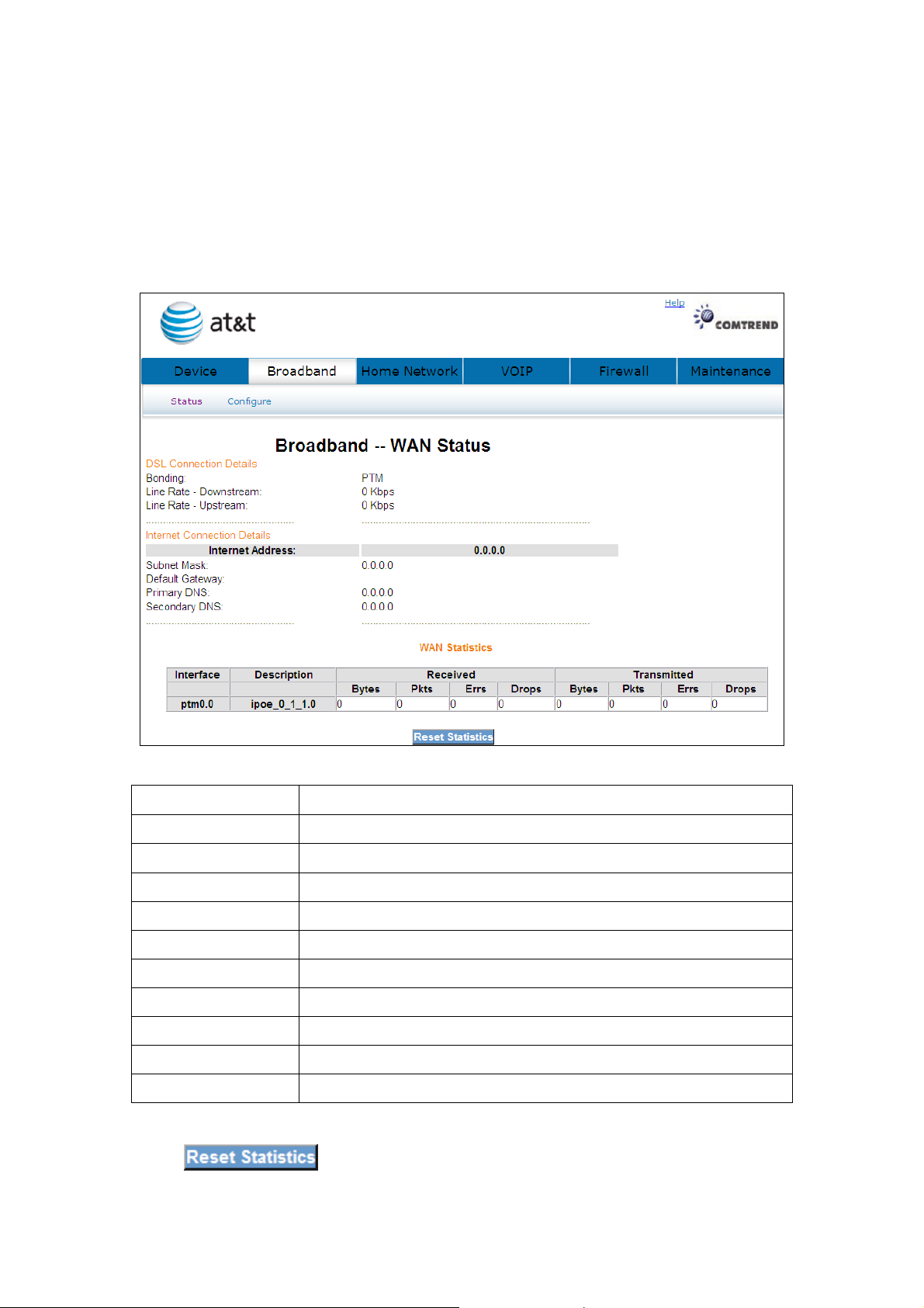
Chapter 5 Broadband
This window shows the existing WAN status.
5.1 Status
Click Broadband to display the status of all configured PVC(s).
Port/VPI/VCI Shows the values of the ATM Port/VPI/VCI
VLAN Mux Shows 802.1Q VLAN ID
Con. ID Shows the connection ID
Category Shows the ATM service classes
Service Shows the name for WAN connection
Interface Shows connection interfaces
Protocol Shows the connection type, such as PPPoE, PPPoA, etc.
IGMP Shows the statue of the IGMP function
State Shows the connection state of the WAN connection
Status Lists the status of DSL link
IP Address Shows IP address for WAN interface
Click
to reset the status of all configured PVC(s).
39
Page 41
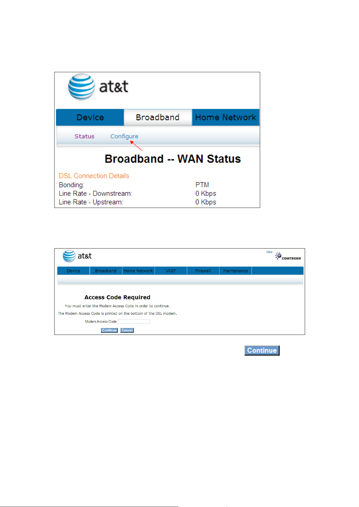
5.2 Configure
Click Configure will bring up the following window.
Input the access code (which is located ______) and click the button.
The options are shown (on the following page)
40
Page 42
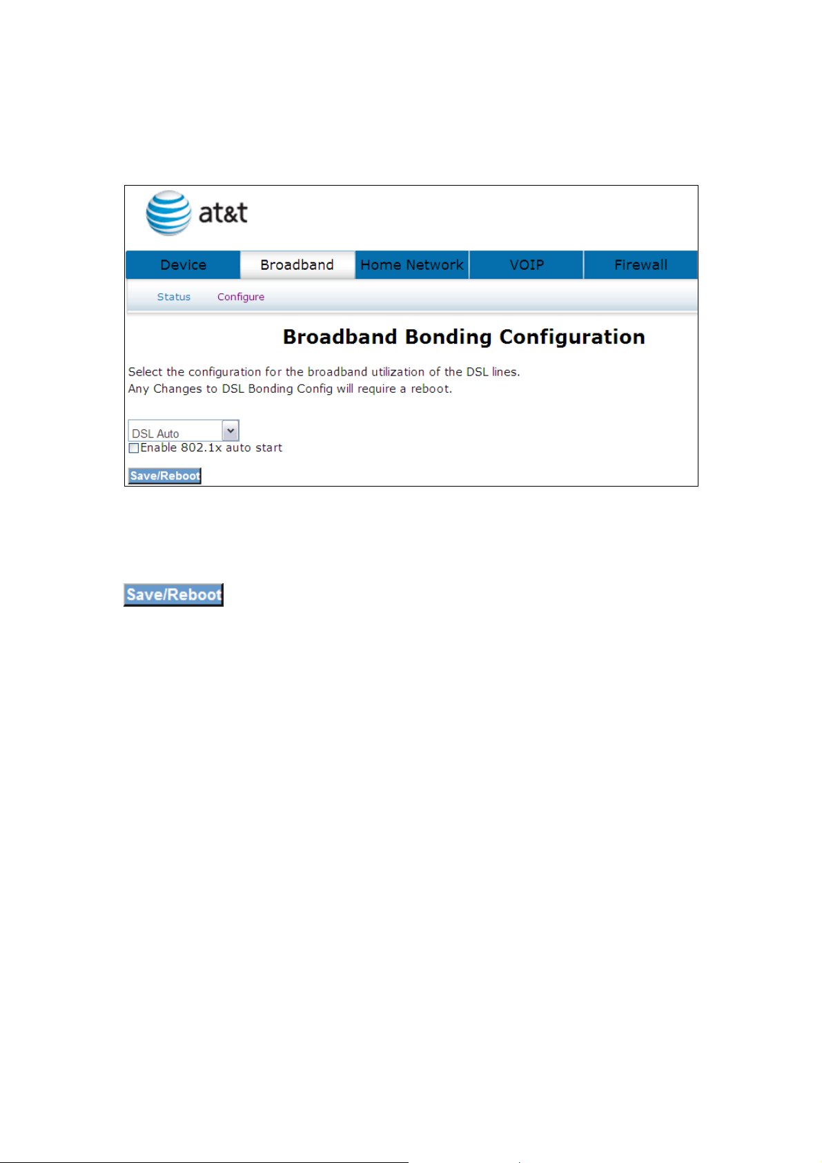
Select the configuration for the broadband utilization of the DSL lines. Any Changes
to DSL Bonding Config will require a reboot.
Select one of the three options (DSL Auto, DSL on inner pair, DSL on outer pair) from
the drop down menu and tick the Enable 802.1x auto start box if required. Click the
button to confirm your choice(s).
41
Page 43
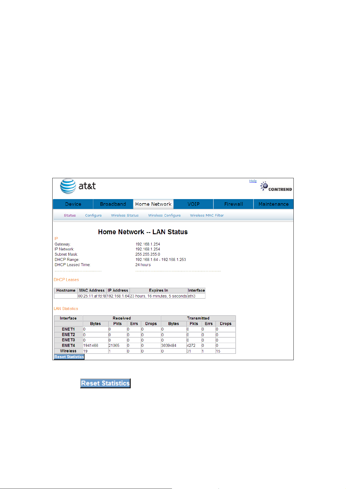
Chapter 6 Home Network
The Home Network – LAN Status screen shows interface statistics for Ethernet and
Wireless interfaces.
6.1 LAN Status
The Network Statistics screen shows interface statistics for LAN of Ethernet
interface. Here provides byte transfer, packet transfer, Error and Drop statistics for
the LAN interface.)
Click the button to refresh this screen.
42
Page 44
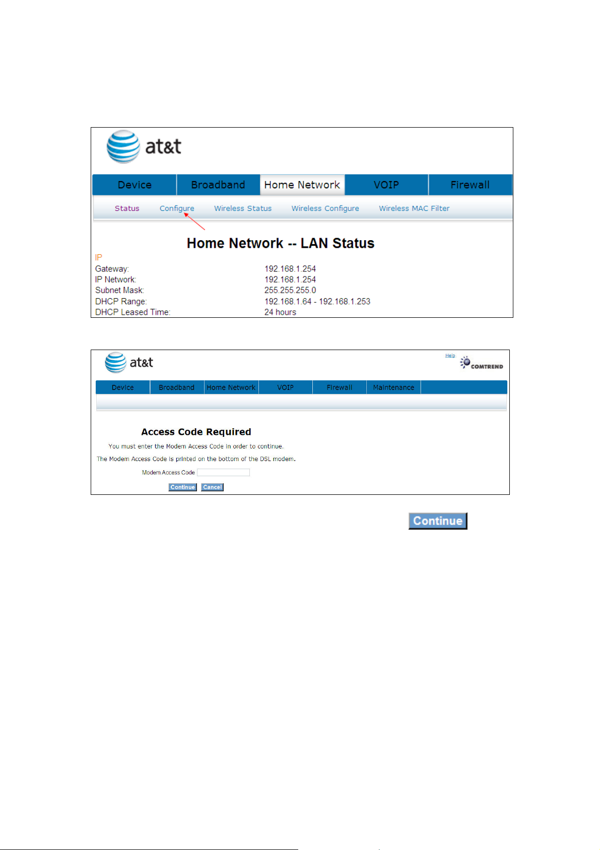
6.2 Configure
Click Configure to bring up the following window.
Input the access code (which is located ______) and click the button.
The options are shown (on the following page)
43
Page 45
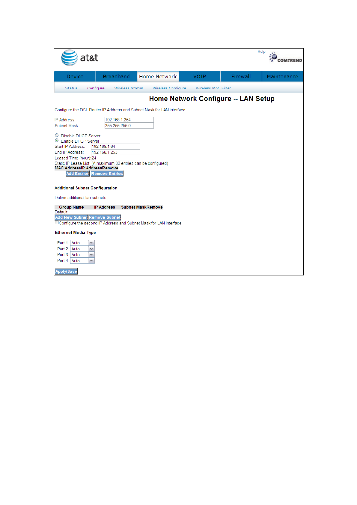
Configure the DSL router IP address and subnet mask for the LAN interface.
IP ADDRESS: ENTER THE IP ADDRESS FOR THE LAN PORT.
SUBNET MASK: ENTER THE SUBNET MASK FOR THE LAN PORT.
DHCP Server: To enable DHCP, select Enable DHCP server and enter Start and
End IP addresses and the Leased Time. This setting configures the
router to automatically assign IP, default gateway and DNS server
addresses to every PC on your LAN.
Static IP Lease List: A maximum of 32 entries can be configured.
44
Page 46
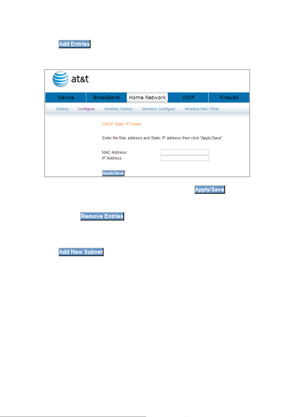
Click
displayed.
to add a DHCP static IP lease. The following window will be
Input the MAC address and Static IP address and then click
To remove an entry, tick the corresponding checkbox in the Remove column and
then click the button.
Click to input the secondary subnet mask for the LAN port.
45
Page 47
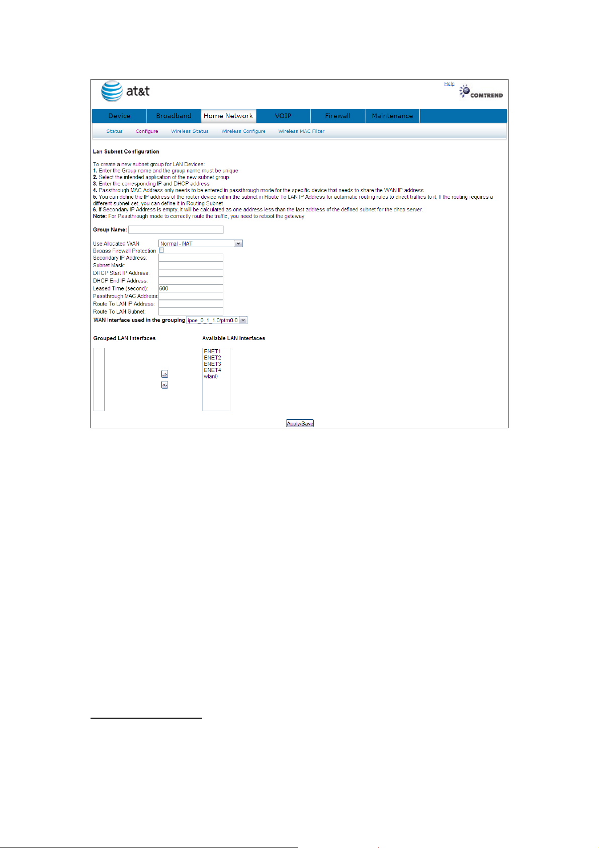
To create a new subnet group for LAN Devices:
1. Enter the Group name and the group name must be unique
2. Select the intended application of the new subnet group
3. Enter the corresponding IP and DHCP address
4. Passthrough MAC Address only needs to be entered in passthrough mode for the
specific device that needs to share the WAN IP address
5. You can define the IP address of the router device within the subnet in Route To
LAN IP Address for automatic routing rules to direct traffics to it; If the routing
requires a different subnet set, you can define it in Routing Subnet
6. If Secondary IP Address is empty, it will be calculated as one address less than
the last address of the defined subnet for the dhcp server.
Note: For Passthrough mode to correctly route the traffic, you need to reboot the
gateway
2ND LAN INTERFACE
To configure a secondary IP address, tick the checkbox as shown here.
46
Page 48
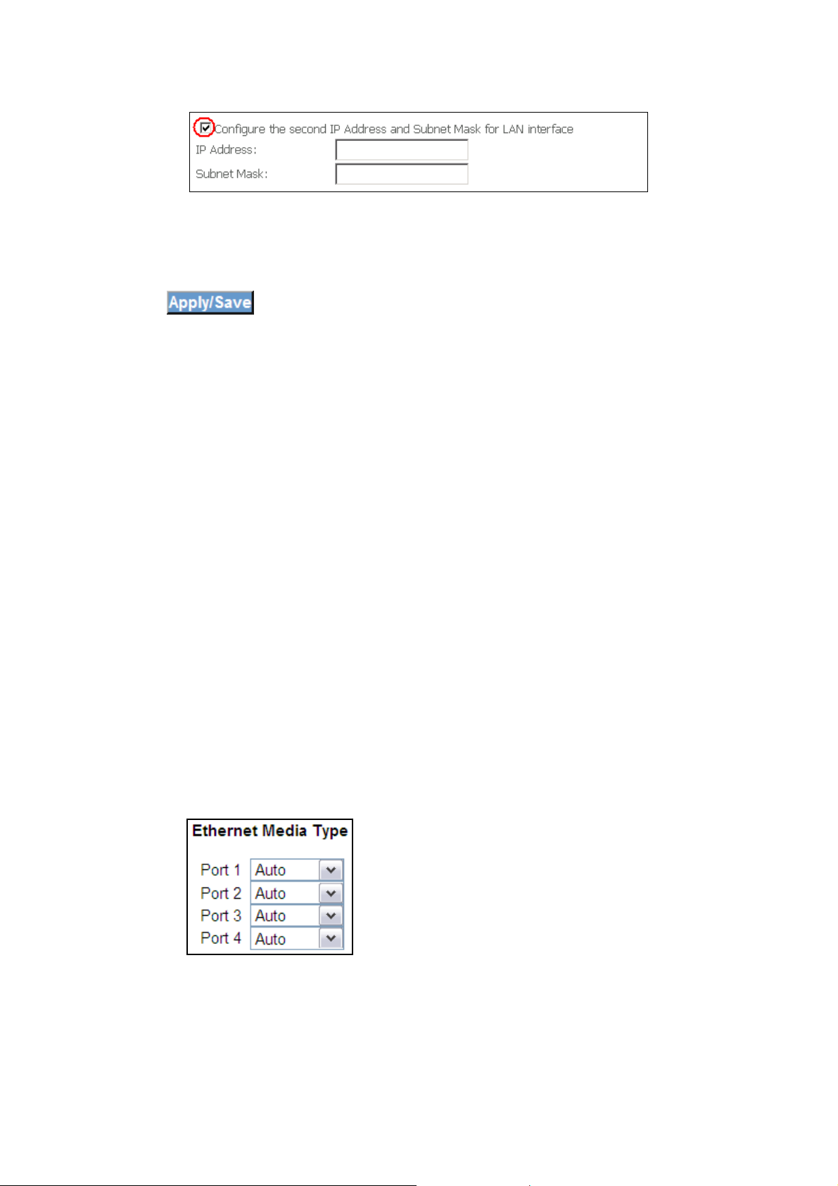
IP Address: Enter the secondary IP address for the LAN port.
Subnet Mask: Enter the secondary subnet mask for the LAN port.
Click to confirm.
Ethernet Media Type: Each LAN port has Speed/Duplex Negotiation detection
capability, the LAN ports detect the speed (for example, 10MBps, 100Mbps) and
duplex (half-duplex or full-duplex) settings of the device on the other end of the
wire and subsequently adjusts to match those settings. During speed/duplex
negotiation the device transmits its own abilities to the peer device so that the peer
can use the appropriate settings.
Auto: Auto detects Speed/Duplex Negotiation
10_Half: The speed limit is 10M and Duplex Negotiation is half.
10_Full: The speed limit is 100M and Duplex Negotiation is full.
100_Half: The speed limit is 100M and Duplex Negotiation is half.
100_Full: The speed limit is 100M and Duplex Negotiation is full.
47
Page 49
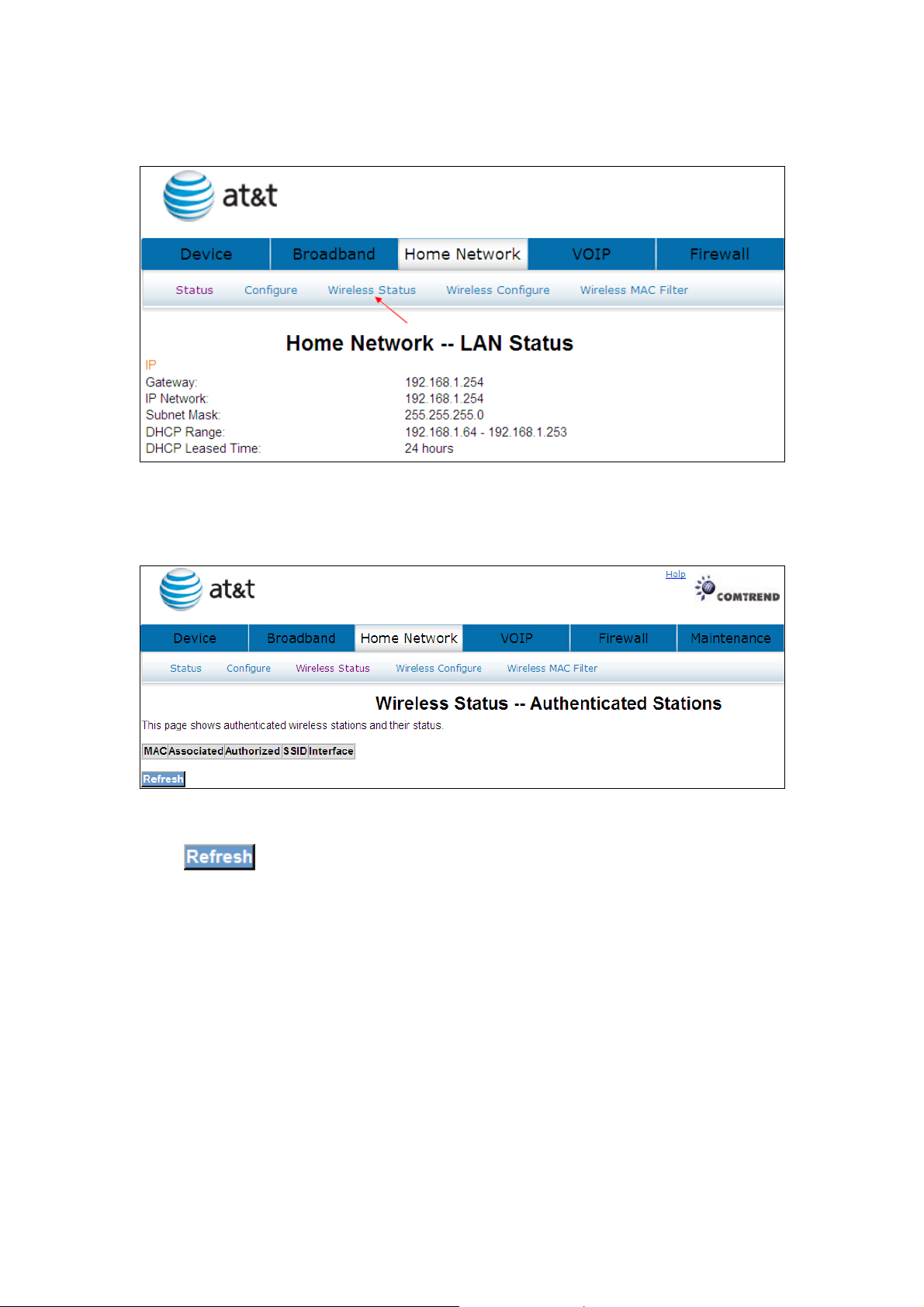
6.3 Wireless Status
Click Wireless Status to bring up the following window.
Click to reset the screen.
48
Page 50
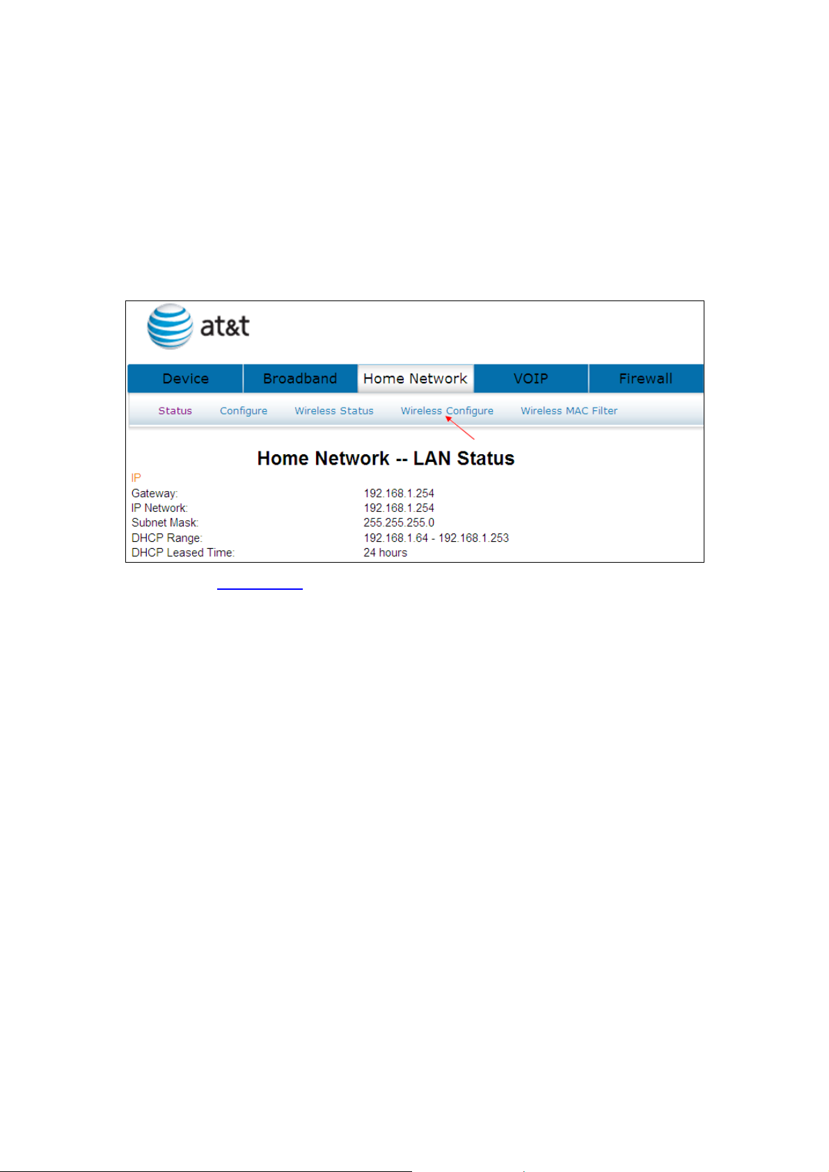
6.4 Wireless Configure
This page allows you to configure basic features of the wireless LAN interface. You
can enable or disable the wireless LAN interface, hide the network from active scans,
set the wireless network name (also known as SSID) and restrict the channel set
based on country requirements.
See section: 4.4 Wireless for a detailed description.
49
Page 51
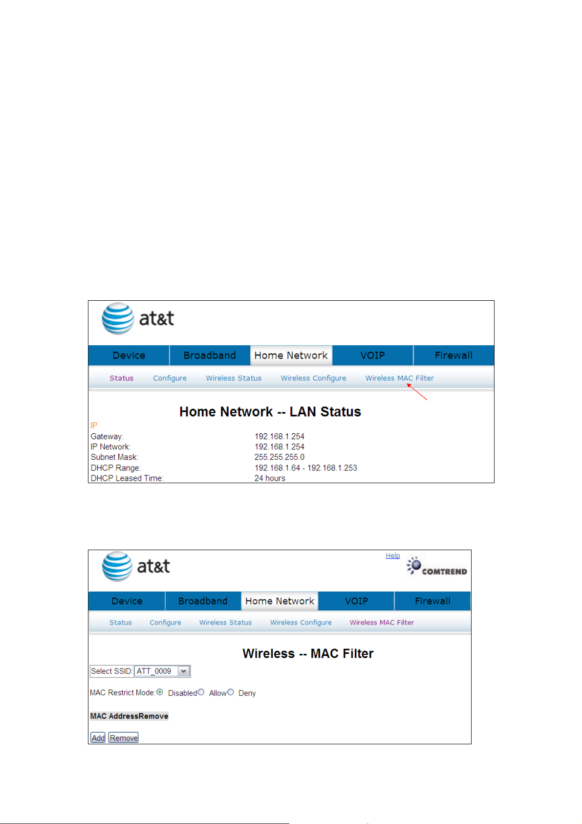
6.5 Wireless MAC Filter
When a device is using MAC filtering, any address not explicitly defined will be
denied access.
This MAC Filter page allows access to be restricted/allowed based on a MAC address.
All (Network Interface Cards) NICs have a unique 48-bit MAC address burned into
the ROM chip on the card. When MAC address filtering is enabled, you are
restricting the NICs that are allowed to connect to your access point. Therefore, an
access point will grant access to any computer that is using a NIC whose MAC
address is on its “allows” list.
Click Wireless MAC Filter to bring up the following window.
50
Page 52
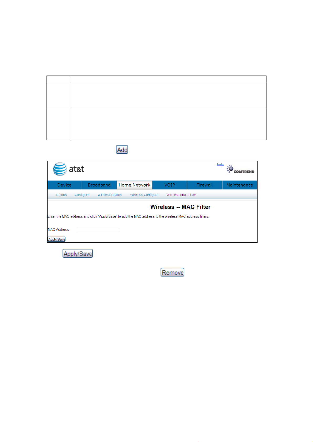
MAC Restrict mode: Off- disables MAC filtering; Allow – permits access for the
byte convention: xx:xx:xx:xx:xx:xx where
specified MAC address; deny; reject access of the specified MAC address, then click
the SET button.
Option
MAC
Restrict
Mode
MAC
Address
To add a MAC entry, click and input a MAC address
Description
Radio buttons that allow settings of;
Off: MAC filtering function is disabled.
Allow: Permits PCs with listed MAC addresses to connect to access point.
Deny: Prevents PCs with listed MAC from connecting to the access point.
Lists the MAC addresses subject to the Off, Allow, or Deny instruction.
The Add button prompts an entry field that requires you type in a MAC
address in a two-character, 6xx are hexadecimal numbers. The maximum number of MAC addresses
that can be added is 60.
Click to add the MAC address to the wireless MAC address filters. To
delete an entry, select the entry, click the button.
51
Page 53

Chapter 7 VOIP
This chapter first describes the various options for configuration of the SIP voice
service. It then provides detailed instructions for making telephone calls using VoIP
(Voice over IP) or PSTN (Public Switched Telephone Network)
Session Initiation Protocol (SIP) is a peer-to-peer protocol used for Internet
conferencing, telephony, events notification, presence and instant messaging.
SIP is designed to address the functions of signaling and session management
within a packet telephony network. Signaling allows call information to be carried
across network boundaries. Session management provides the ability to control
the attributes of an end-to-end call.
(1) The NexusLink 5700 supports Phone Line (FXS) interface only, which cannot dial to the
local PSTN network.
NOTE: The SIP standard is set by the Internet Engineering Task Force (IETF).
(1)
services.
The SIP standard defines the following agents/servers:
User Agents (UA) - SIP phone clients (hardware or software)
Proxy Server – relays data between UA and external servers
Registrar Server - a server that accepts register requests from UA
Redirect Server – provides an address lookup service to UA
52
Page 54
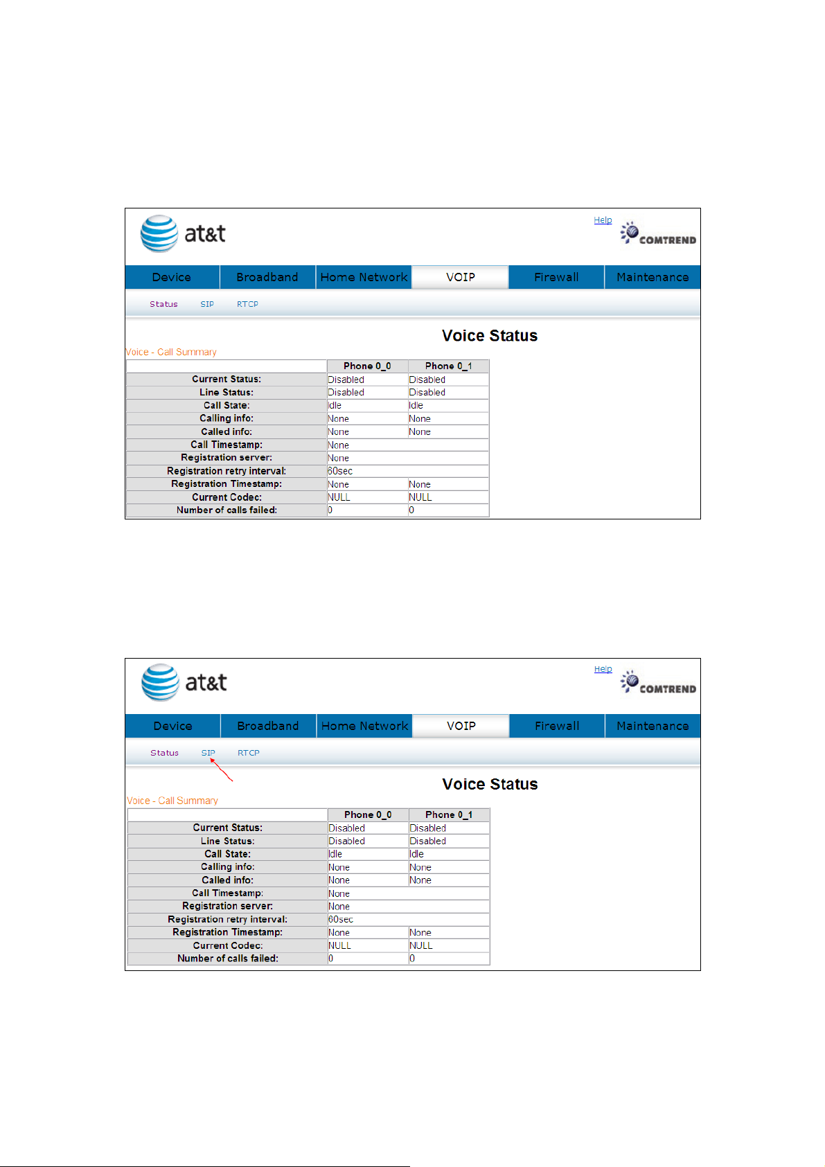
7.1 Status
Displays the call summary.
7.2 SIP
Click SIP to bring up the following window.
The settings of Global Parameters and Service Provider please contact with your ISP
53
Page 55
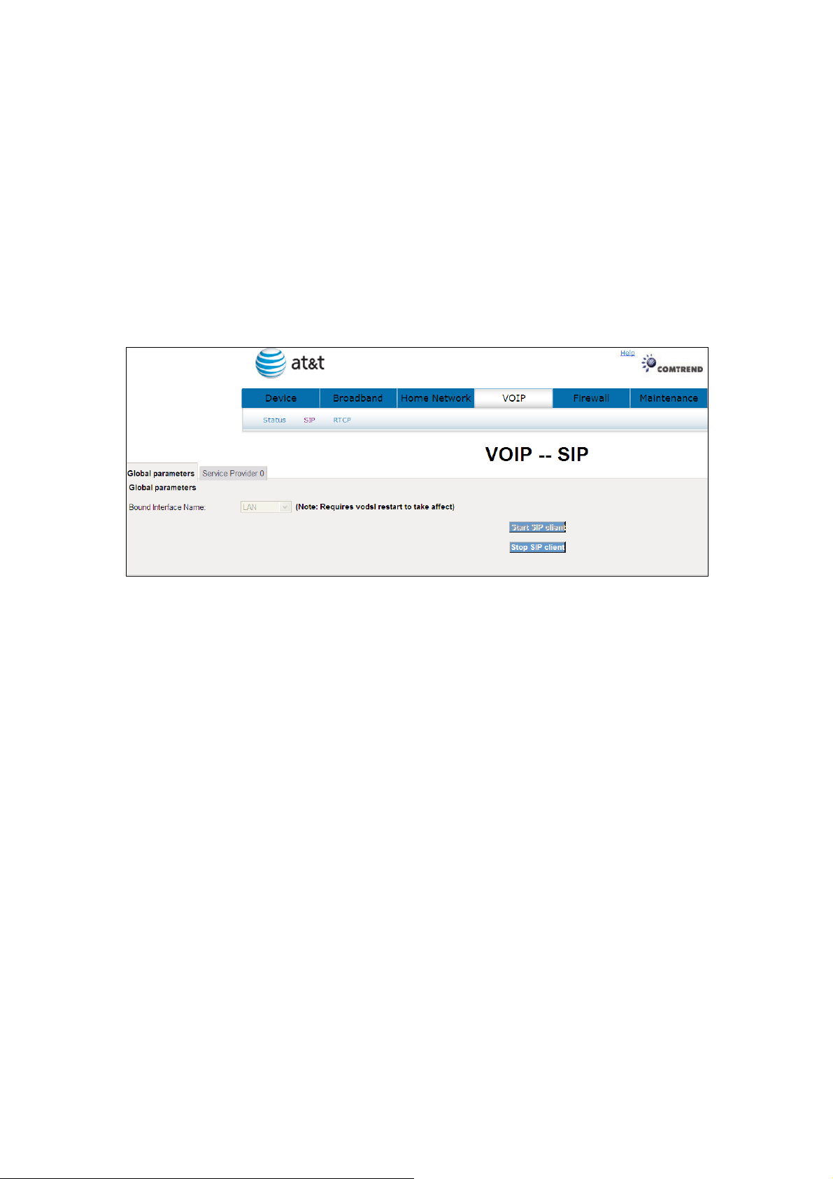
servicer.
7.2.1 Global Parameters
Start SIP client: Active SIP service (Internet telephony calls)
Stop SIP client: Inactive SIP service (Internet telephony calls)
About the setting of Global Parameters or want to know any detail information
please contact with your ISP servicer.
A common parameter setting.
54
Page 56
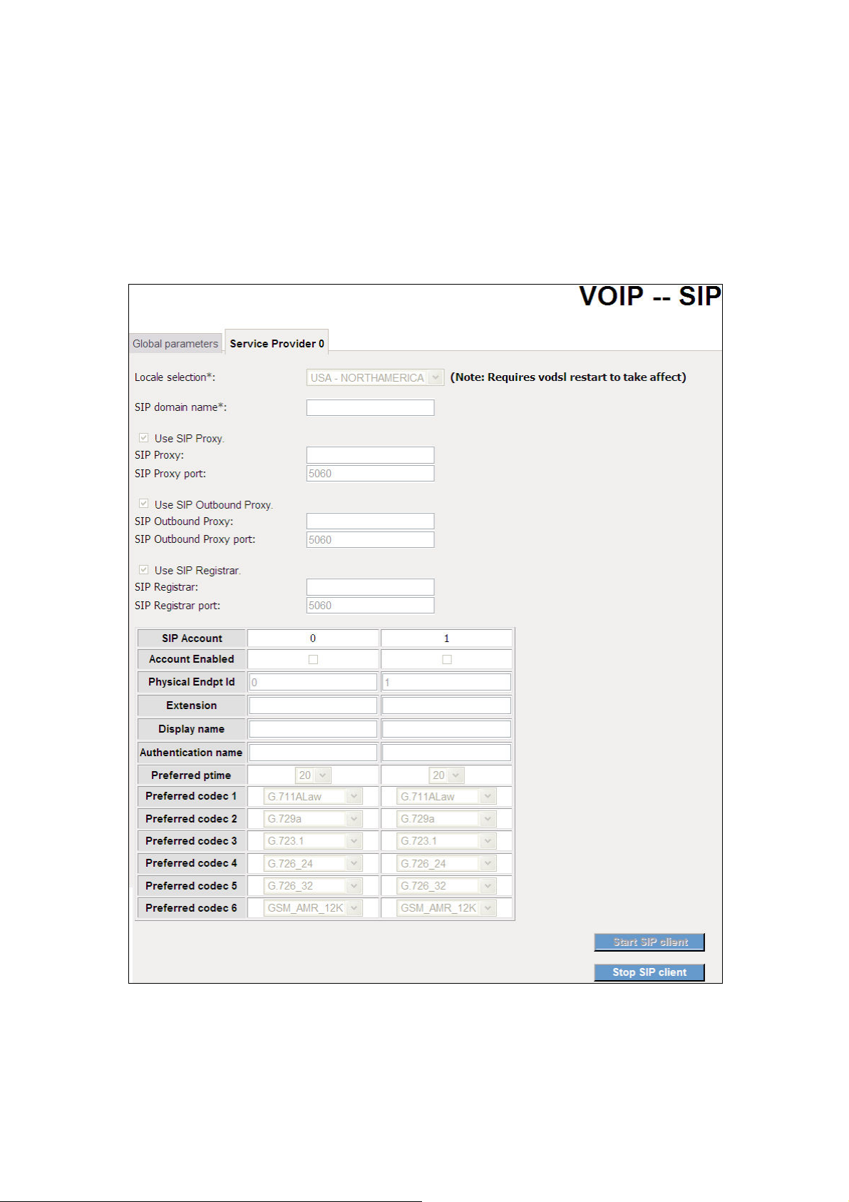
7.2.2 Service Provider
This screen contains basic SIP configuration settings.
Start SIP client: Active SIP service (Internet telephony calls)
Stop SIP client: Inactive SIP service (Internet telephony calls)
About the setting of Service Provider or want to know any detail information please
contact with your ISP servicer.
VoIP settings are set by your service provider.
55
Page 57

Once settings are configured, click
Click to cease using the service.
to begin using the service.
56
Page 58
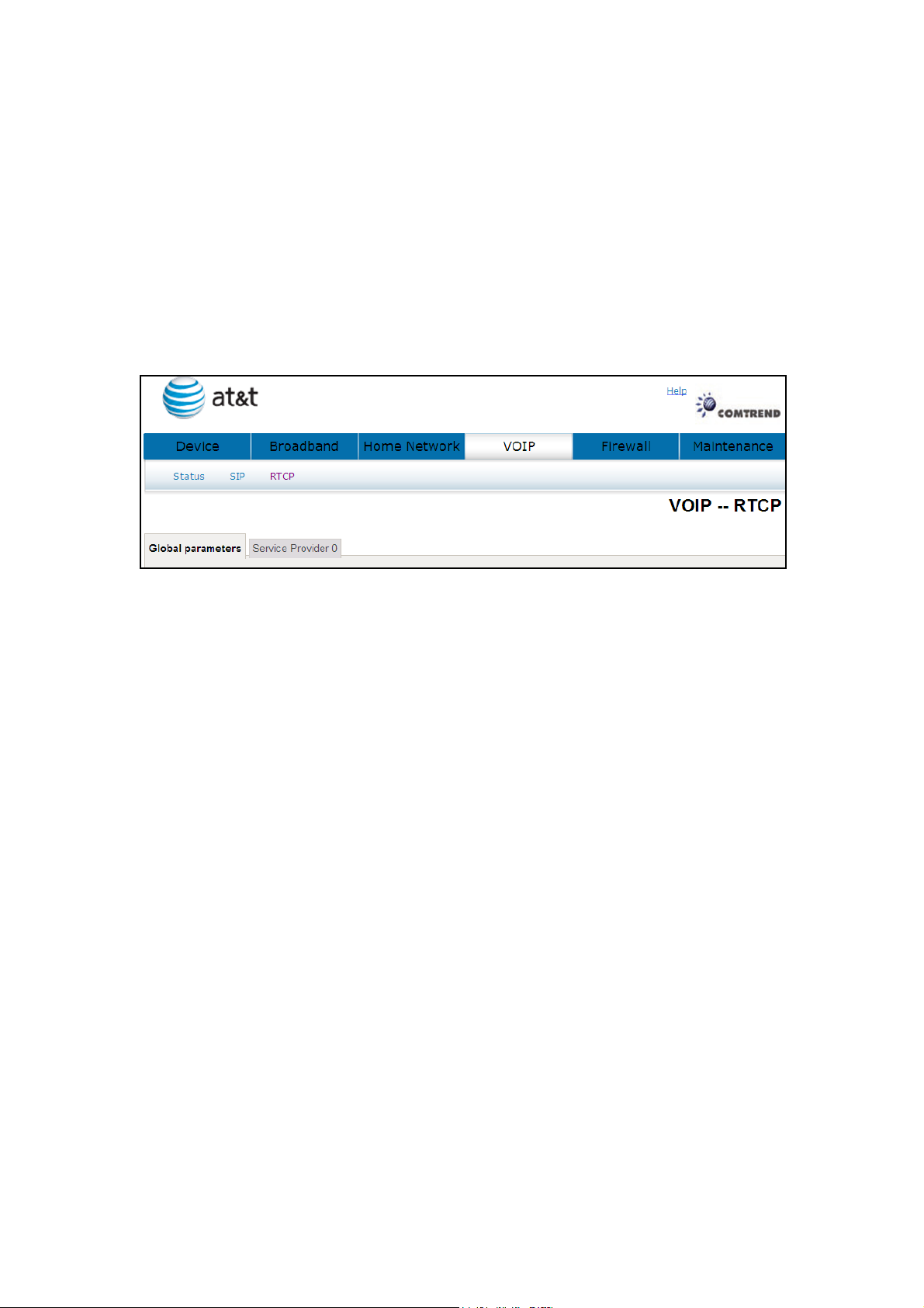
7.3 RTCP
For VoIP voice quality reporting, a SIP event package is specified to report RTCP and
RTCP-XR summaries; SIP method options are provided to convey such events to a
collector.
7.3.1 Global Parameters
A common parameter setting.
57
Page 59
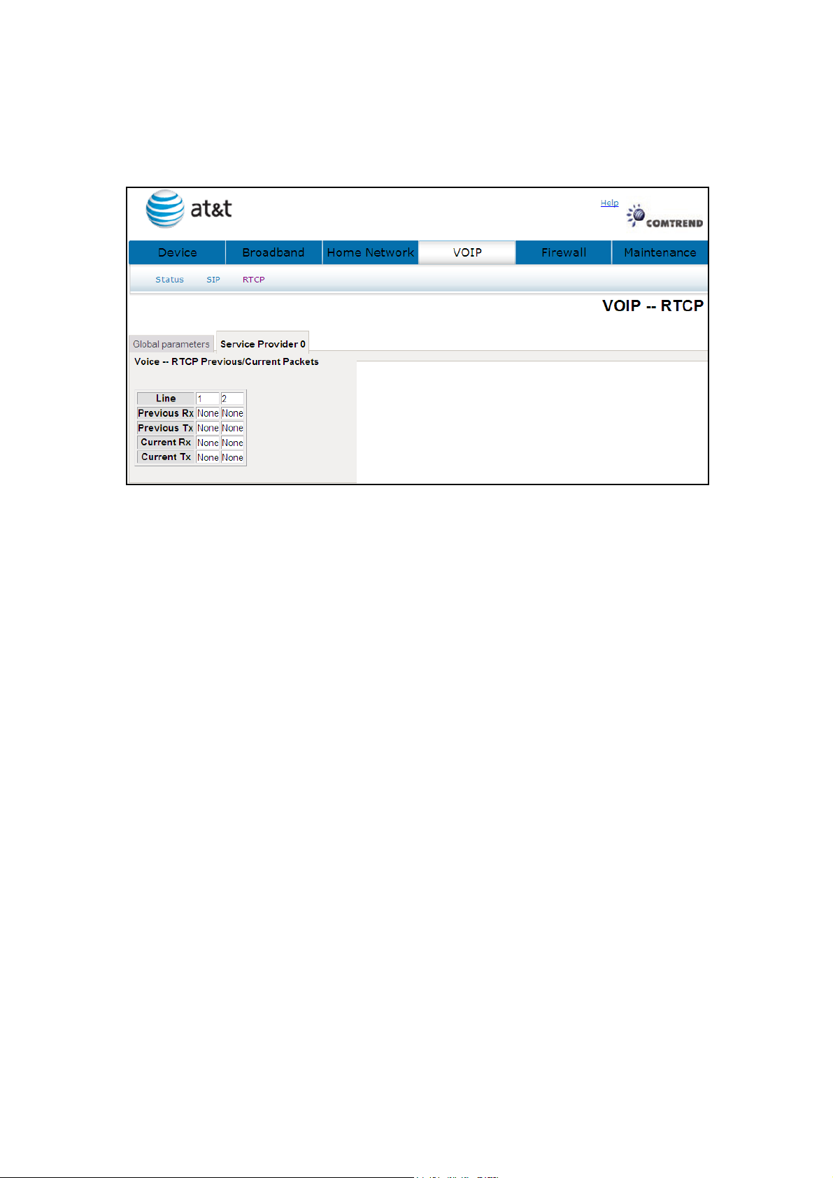
7.3.2 Service Provider
This screen contains basic SIP configuration settings.
NL5700 will collect and report on a set of voice quality metrics on a per-call basis to a
centralized collector via SIP.
There are two primary components: First, an IETF-proposed specification is customized to
define the format of a Voice Quality (VQ) report and to select metrics contained within the
report. Second, two candidates SIP methods are proposed for the gateway to convey the VQ
report to a third-party collector.
58
Page 60

7.4 Telephone Calls
AT&T CVoIP Star Codes
This tab is a list of star codes planned for use by AT&T CVoIP.
Code
TBD Blind Transfer - Invoke
TBD Call Forwarding to Voice Mail - Activate
*312 Simultaneous Ringing - Activate
*313 Simultaneous Ringing - Deactivate
*370 Call Waiting - Activate (persistent)
*371 Call Waiting - Cancel (persistant)
*372 Call Forwarding Unregistered User - Activate
*373 Call Forwarding Unregistered User - Deactivate
*374 Call Forwarding Unreachable Calls to Voice Mail - Activate
*375 Call Forwarding Unreachable Calls to Voice Mail - Deactivate
*57 Customer originated Trace - Invoke
*61 Distinctive Ring Call Waiting
*63 Selective Call Forwarding - Activate
*64 Selective Call Acceptance - Activate
*66 Automatic Call Back (redial last outbound number) - Invoke
Description
*67 Calling Line Identification - Cancel (make private)
*68 Selective Call Rejection - Activate
*69 Automatic Recall (return last incoming call) - Invoke
*70 Call Waiting - Cancel (mid call)
*70 Call Waiting - Cancel (per call)
*72 Call Forwarding (always) - Activate
*73 Call Forwarding (always) - Deactivate
*74 Speed Call Short
*75 Speed Call Long
*77 Anonymous Call Rejection - Activate
*78 Do not Disturb - Activate
*78 Call Park
*79 Do not Disturb - Deactivate
*79 Call Park Retrieve
*80 Selective Call Rejection - Deactivate
59
Page 61

*81
*82 Calling Line Identification Restriction – Cancel (make public)
*83 Selective Call Forwarding - Deactivate
*84 Selective Call Acceptance - Deactivate
*86 Automatic Call Back Deactivate
*87 Anonymous Call Rejection - Deactivate
*89 Automatic Recall Deactivate
*90 Call Forwarding Busy - Activate
*91 Call Forwarding Busy - Deactivate
*92 Call Forwarding No Answer - Activate
*93 Call Forwarding No Answer - Deactivate
*95 Automatic Call Control VRU
*98 Voicemail
*99 Trunk Answer Any Station
N/A Ring Back when Free (RBwF) - Cancel
Distinctive ring
60
Page 62
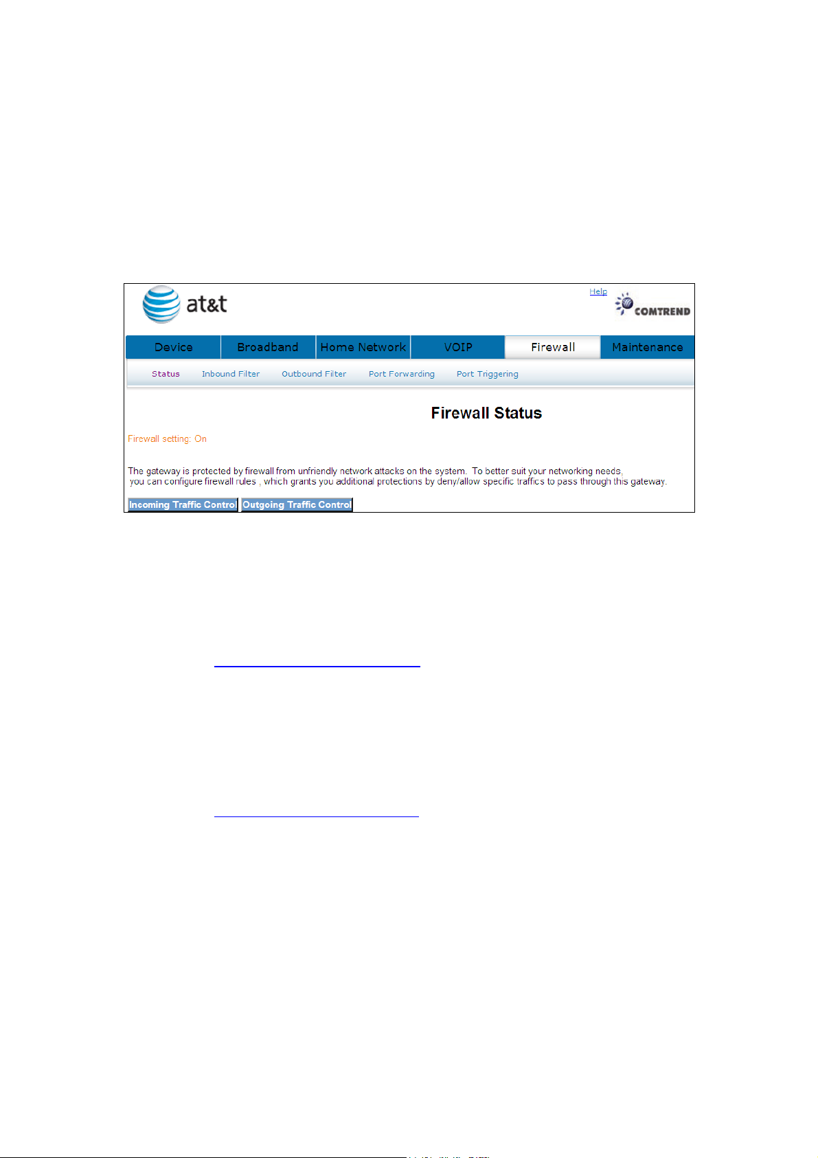
Chapter 8 Firewall
The gateway is protected by firewall from unfriendly network attacks on the system.
8.1 Status
Displays your firewall setting.
8.2 Inbound Filter
See section: 4.7.1 Incoming Traffic Control for a detailed description.
8.3 Outbound Filter
See section: 4.7.2 Outgoing Traffic Control for a detailed description
61
Page 63
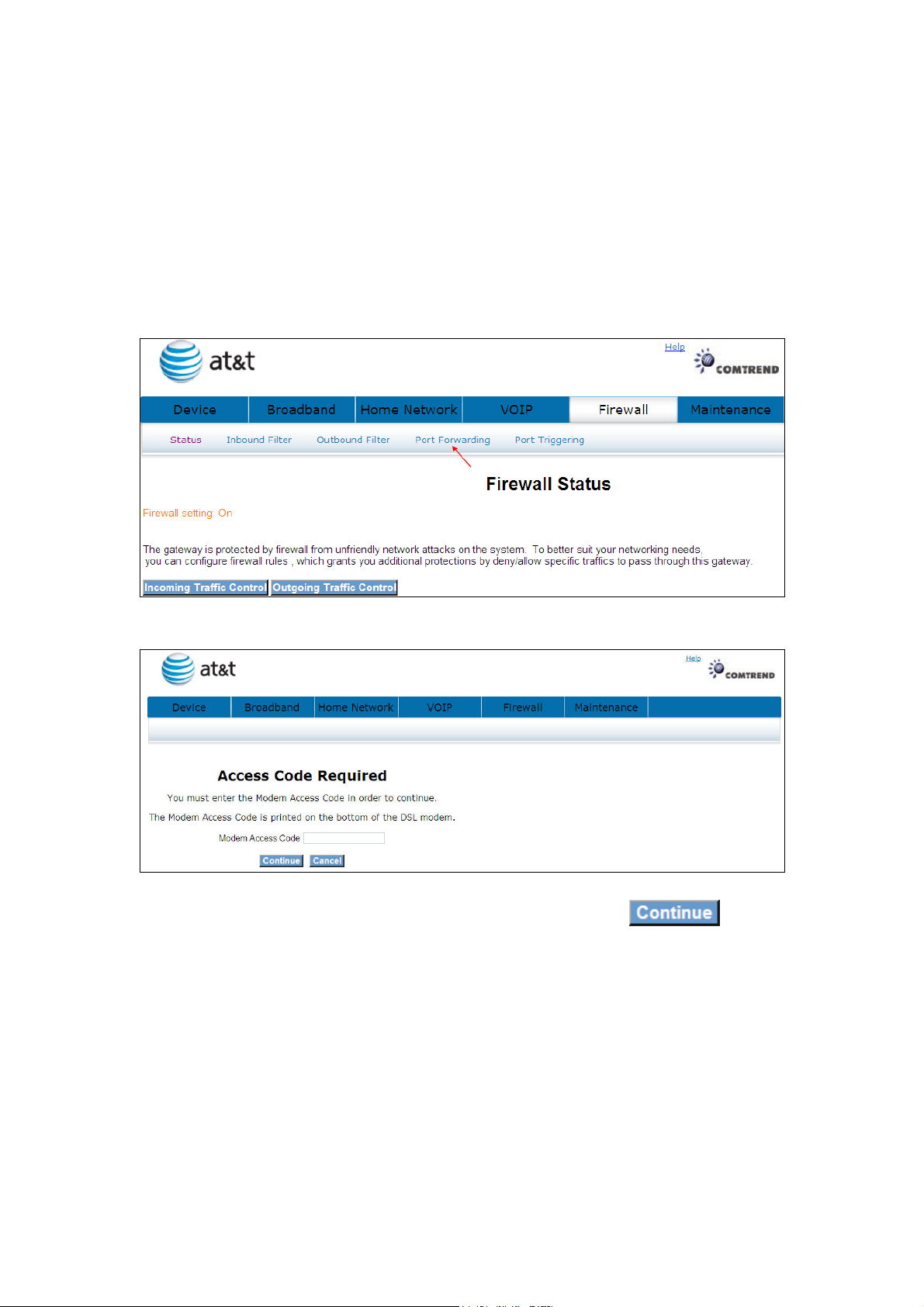
8.4 Port Forwarding
Port forwarding allows you to direct incoming traffic from the WAN side (identified by
Protocol and External port) to the Internal server with private IP addresses on the
LAN side. The Internal port is required only if the external port needs to be
converted to a different port number used by the server on the LAN side.
A maximum of 32 entries can be configured.
Click Port Forwarding will bring up the following window.
Input the access code (which is located ______) and click the button.
The options are shown (on the following page)
62
Page 64
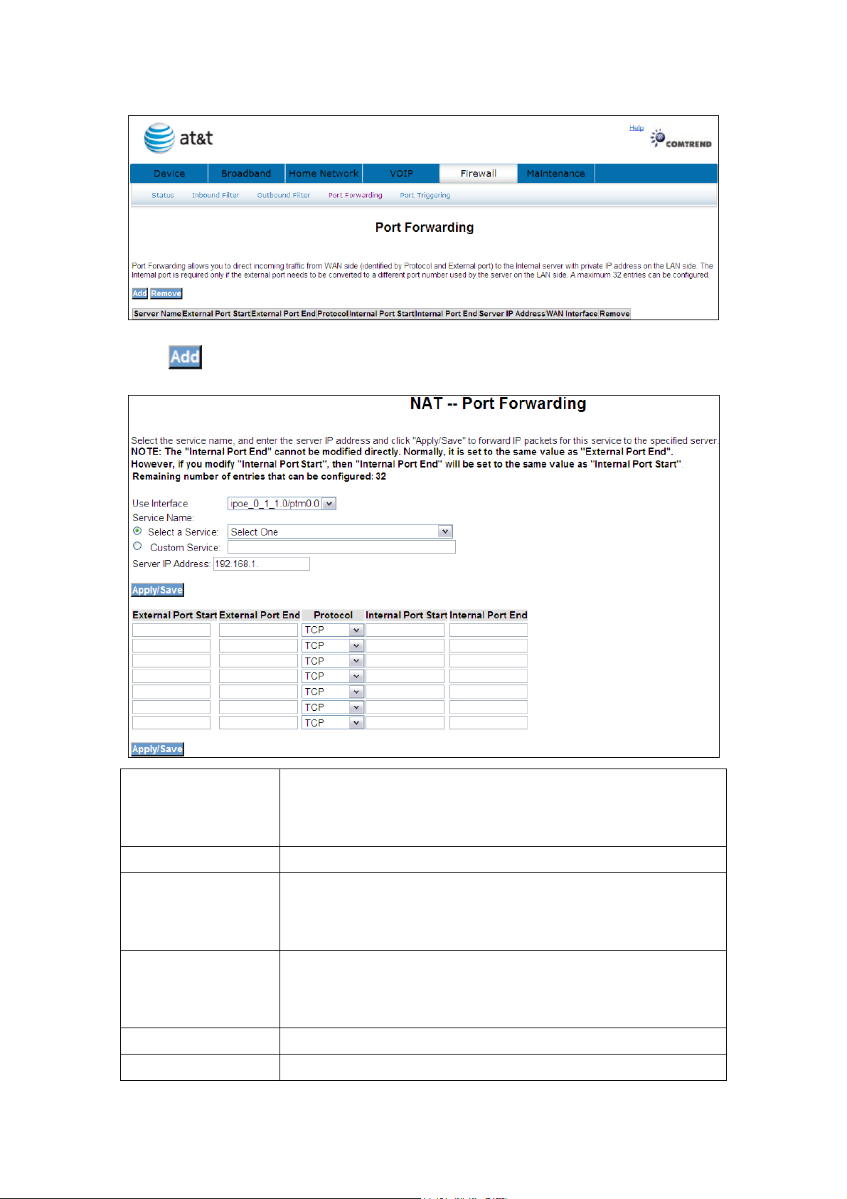
Click to display the following window.
Select a Service
or
Custom Server
Server IP Address Enter the IP address for the server.
External Port Start Enter the starting external port number (when you select
External Port End Enter the ending external port number (when you select
Protocol User can select from: TCP, TCP/UDP or UDP.
Internal Port Start Enter the internal port starting number (when you select
User should select the service from the list.
or
User can enter the name of their choice.
Custom Server). When a service is selected the port ranges
are automatically configured.
Custom Server). When a service is selected the port ranges
are automatically configured.
63
Page 65

Custom Server). When a service is selected the port ranges
are automatically configured
Internal Port End Enter the internal port ending number (when you select
Custom Server). When a service is selected the port ranges
are automatically configured.
Click to forward IP packets for this service to the specified server.
Click to delete an entry.
64
Page 66
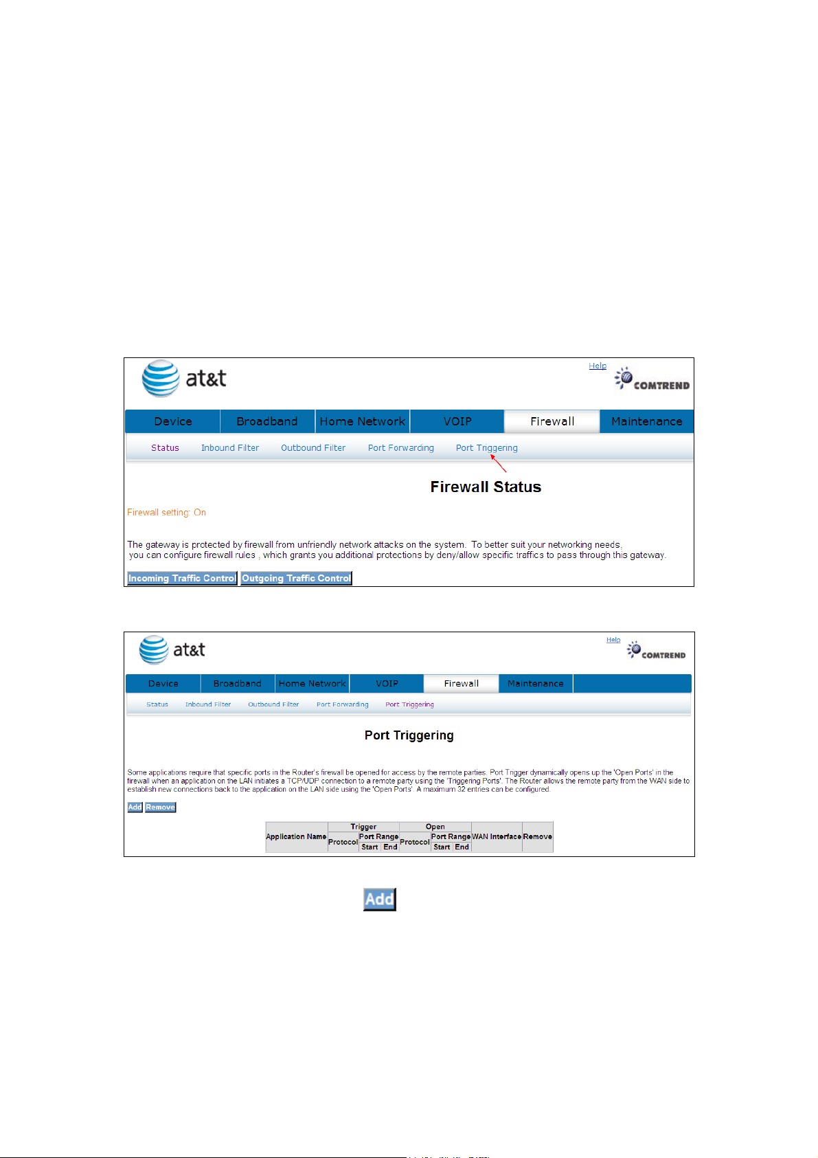
8.5 Port Triggering
Some applications require that specific ports in the router’s firewall be opened for
access by the remote parties. Port Trigger dynamically opens up the ‘Open Ports’ in
the firewall when an application on the LAN initiates a TCP/UDP connection to a
remote party using the ‘Triggering Ports’. The router allows the remote party from
the WAN side to establish new connections back to the application on the LAN side
using the ‘Open Ports’. A maximum 32 entries can be configured.
Click Port Triggering to bring up the following window.
To add a Trigger Port, simply click . The following will be displayed.
65
Page 67
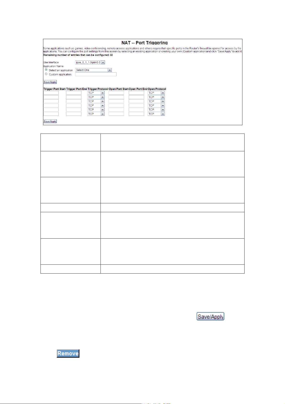
Select an Application
Or Custom Application
Trigger Port Start Enter the starting trigger port number (when you select
Trigger Port End Enter the ending trigger port number (when you select
Trigger Protocol User can select from: TCP, TCP/UDP or UDP.
Open Port Start Enter the starting open port number (when you select
Open Port End Enter the ending open port number (when you select
Open Protocol User can select from: TCP, TCP/UDP or UDP.
User should select the application from the list.
Or User can enter the name of their choice.
custom application). When an application is selected the
port ranges are automatically configured.
custom application). When an application is selected the
port ranges are automatically configured.
custom application). When an application is selected the
port ranges are automatically configured.
custom application). When an application is selected the
port ranges are automatically configured.
You can configure the port settings from this screen by selecting an existing
application or creating your own (Custom application)and click to add
it.
Click
to delete an entry.
66
Page 68
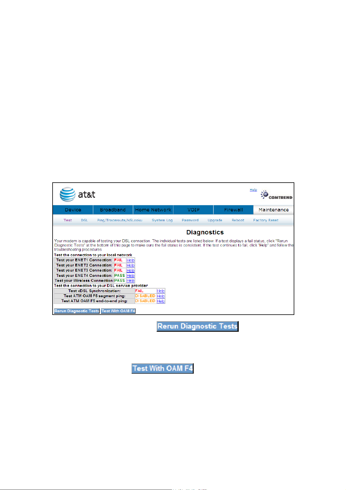
Chapter 9 Maintenance
The Diagnostics menu provides feedback on the connection status of the device
and the ADSL link. The individual tests are listed below.
9.1 Test
The individual tests are listed below. If a test displays a fail status, click "Rerun
Diagnostic Tests" at the bottom of this page to make sure the fail status is consistent.
If the test continues to fail, click "Help" and follow the troubleshooting procedures.
If a test displays a fail status, click at the bottom of
this page to make sure the fail status is consistent. If the test continues to fail, click
Help and follow the troubleshooting procedures. To test the connection with your
DSL service provider, click
67
Page 69
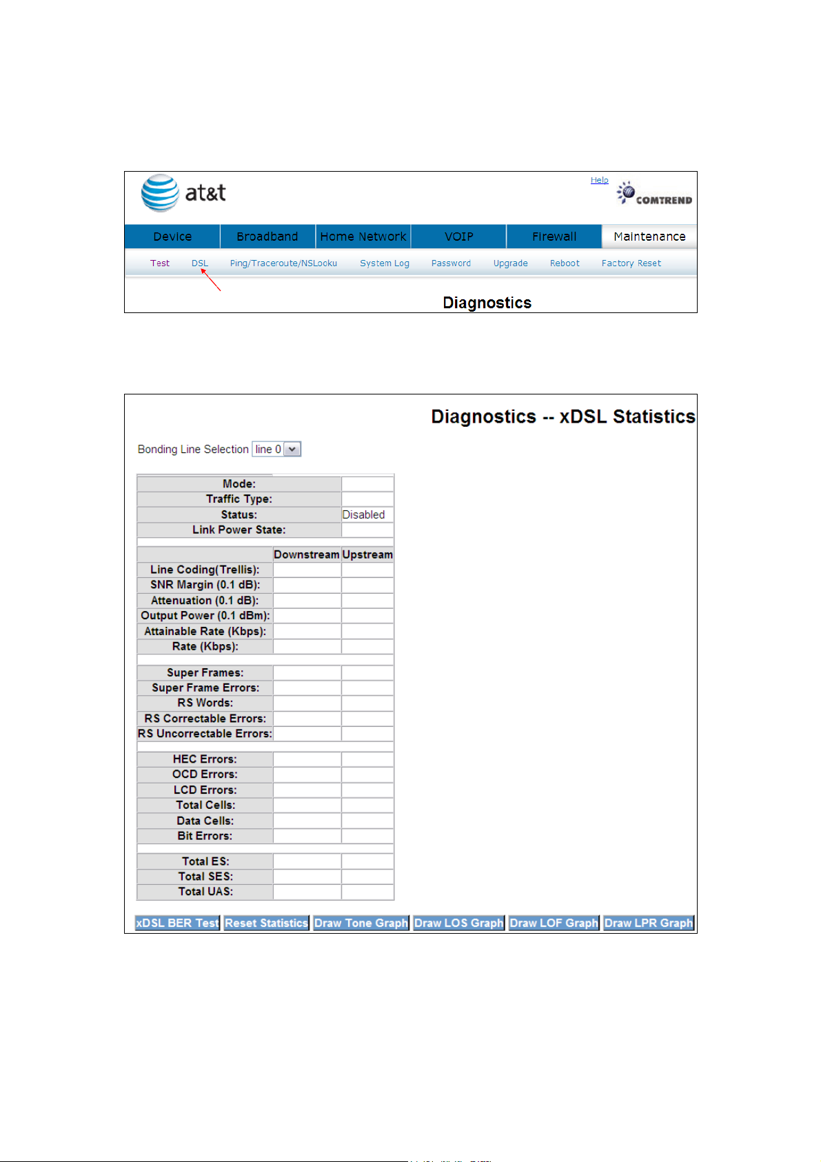
9.2 DSL
Click DSL to display the xDSL Diagnostics window.
Consult the table below for descriptions of each field.
68
Page 70

Field Description
wnstream
Mode Line Coding format, that can be selected G.dmt, G.lite,
T1.413, ADSL2
Traffic Type Channel type Interleave or Fast
Status Lists the status of the DSL link
Link Power State Link output power state.
Line Coding Trellis On/Off
SNR Margin (dB) Signal to Noise Ratio (SNR) margin
Attenuation (dB) Estimate of average loop attenuation in the do
direction.
Output Power (dBm) Total upstream output power
Attainable Rate (Kbps) The sync rate you would obtain.
Rate (Kbps) Current sync rate.
Super Frames Total number of super frames
Super Frame Errors Number of super frames received with errors
RS Words Total number of Reed-Solomon code errors
RS Correctable Errors Total Number of RS with correctable errors
RS Uncorrectable Errors Total Number of RS words with uncorrectable errors
HEC Errors Total Number of Header Error Checksum errors
OCD Errors Total Number of out-of-cell Delineation errors
LCD Errors Total number of Loss of Cell Delineation
Total Cells Total number of ATM cells (including idle + data cells)
Data Cells Total number of ATM data cells
Bit Errors Total number of bit errors
Total ES: Total Number of Errored Seconds
Total SES: Total Number of Severely Errored Seconds
Total UAS: Total Number of Unavailable Seconds
9.2.1 xDSL BER Test
Click on the xDSL Statistics screen to test the Bit Error Rate
69
Page 71
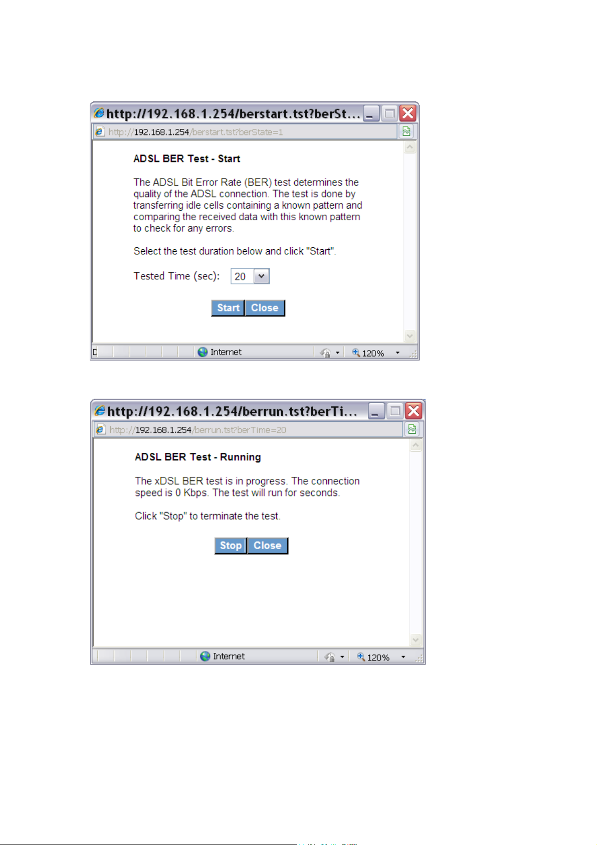
(BER). A small pop-up window will open after the button is pressed, as shown below.
Click Start to start the test or click Close to cancel the test.
After the BER testing is complete, the pop-up window will display as follows.
70
Page 72
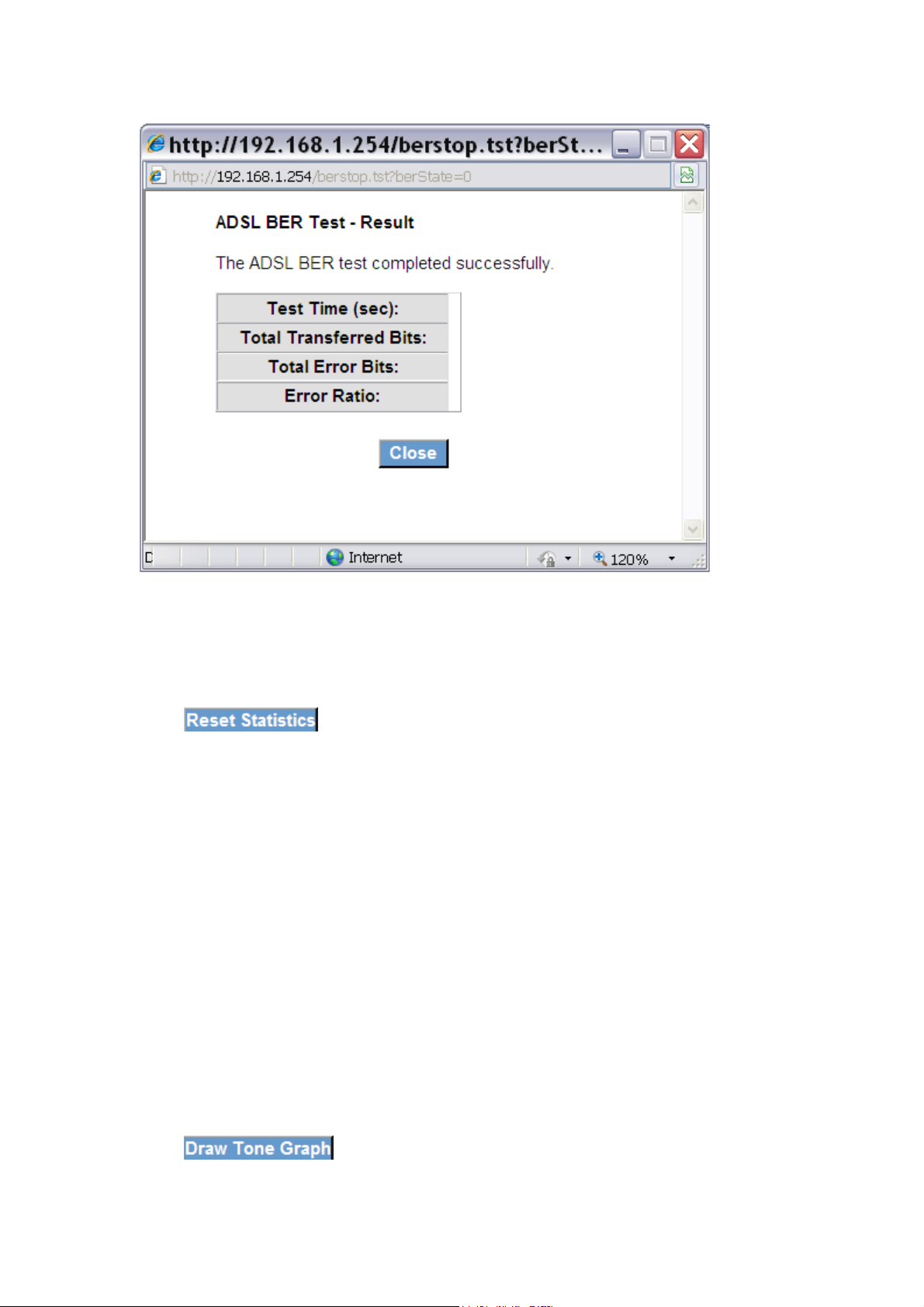
9.2.2 Reset Statistics
Click to refresh the screen.
9.2.3 Draw Graph Tone
Click to display the current xDSL bits per tone status. The X
axis represents Tone Number and the Y axis represents Bit Allocation.
71
Page 73
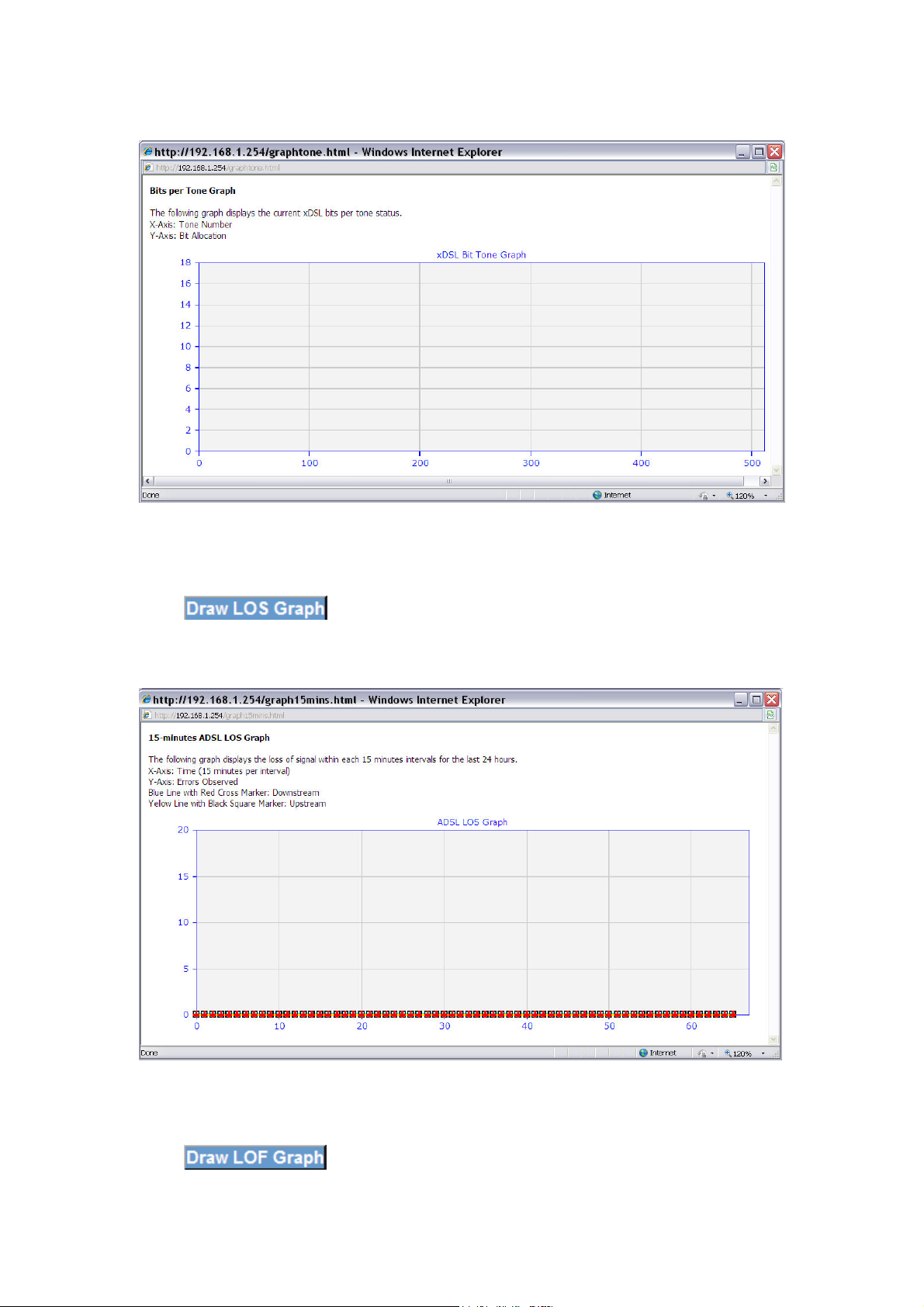
9.2.4 Draw Loss of Signal Graph
Click to display the loss of signal within each 15 minute intervals
for the last 24 hours. The X axis represents Time and the Y axis represents Errors
Observed.
9.2.5 Draw Loss of Frames Graph
Click to display the loss of frames within each 15 minute
72
Page 74
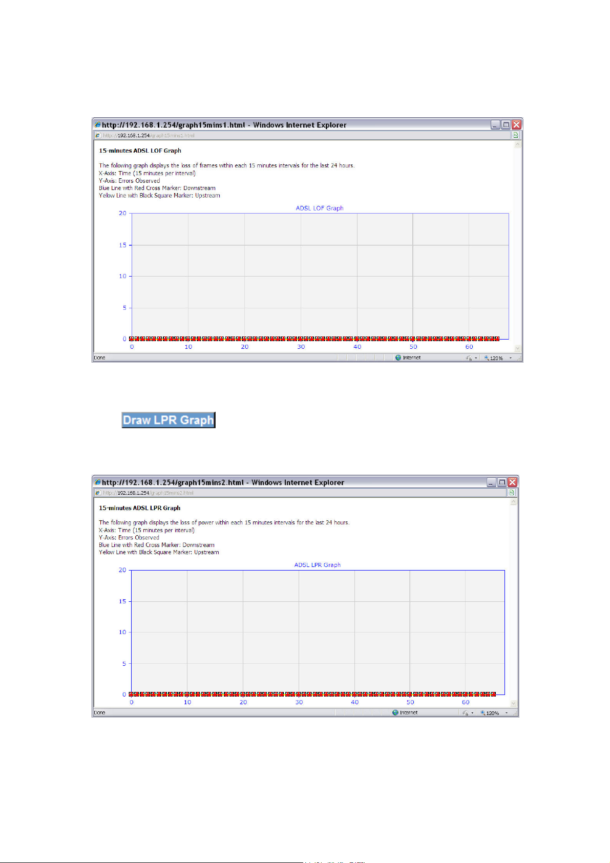
intervals for the last 24 hours. The X axis represents Time and the Y axis represents
Errors Observed.
9.2.6 Loss of Power
Click to display the loss of power within each 15 minute intervals
for the last 24 hours. The X axis represents Time and the Y axis represents Errors
Observed.
73
Page 75
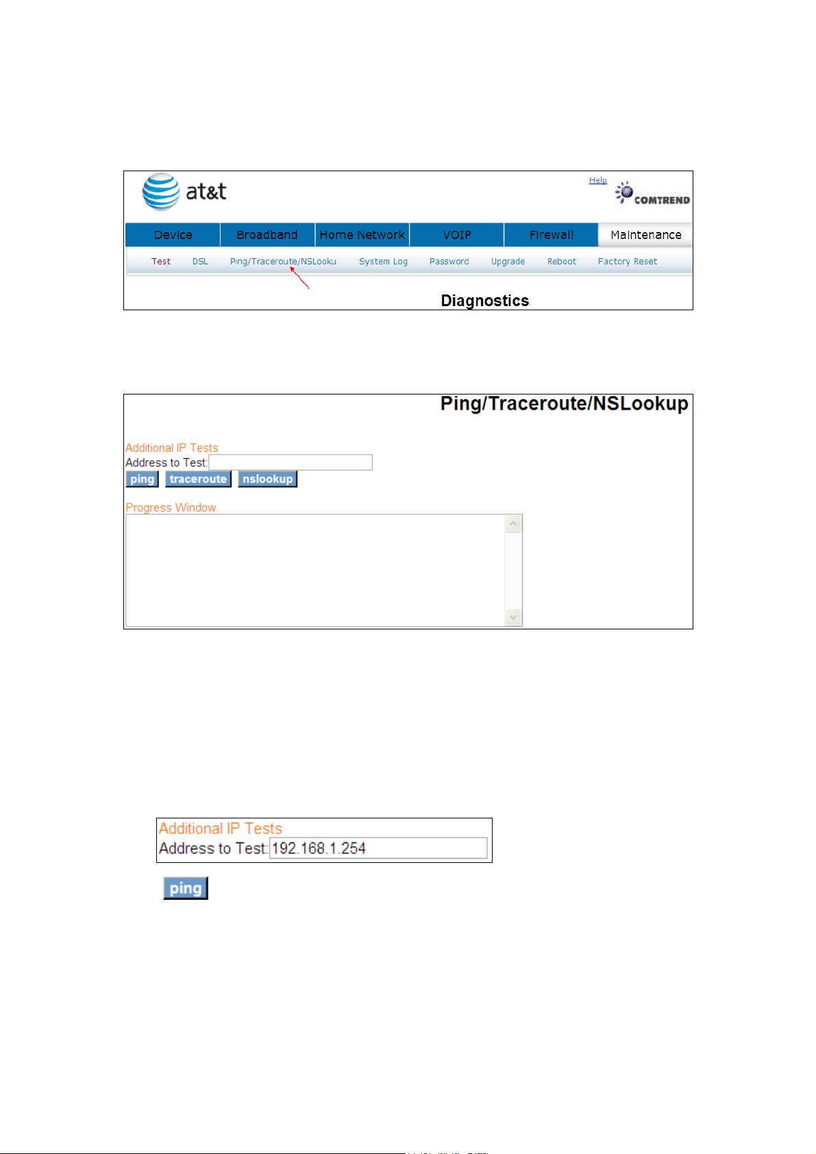
9.3 Ping/Traceroute/NSLookup
Click Ping/Traceroute/NSLookup to bring up the following window.
9.3.1 Ping
Ping: Used to test the reach ability of a host on an Internet Protocol (IP) network
and to measure the round-trip time for messages sent from the originating host to
a destination computer
Click to seek a reply from an IP address.
74
Page 76
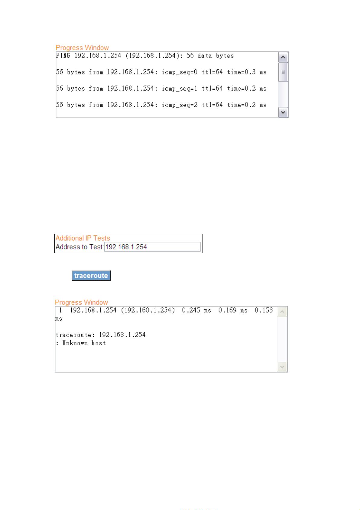
9.3.2 TraceRoute
TraceRoute: Used to show the route taken by packets across an IP network
Traceroute is often used for network troubleshooting. By showing a list of routers
traversed, it allows the user to identify the path taken to reach a particular
destination on the network.
Click to trace the route of an IP address.
9.3.3 NSLookup
Nslookup:Used to query Domain Name System (DNS) servers to find DNS details,
including IP addresses of a particular computer, MX records for a domain and the NS
servers of a domain.
75
Page 77
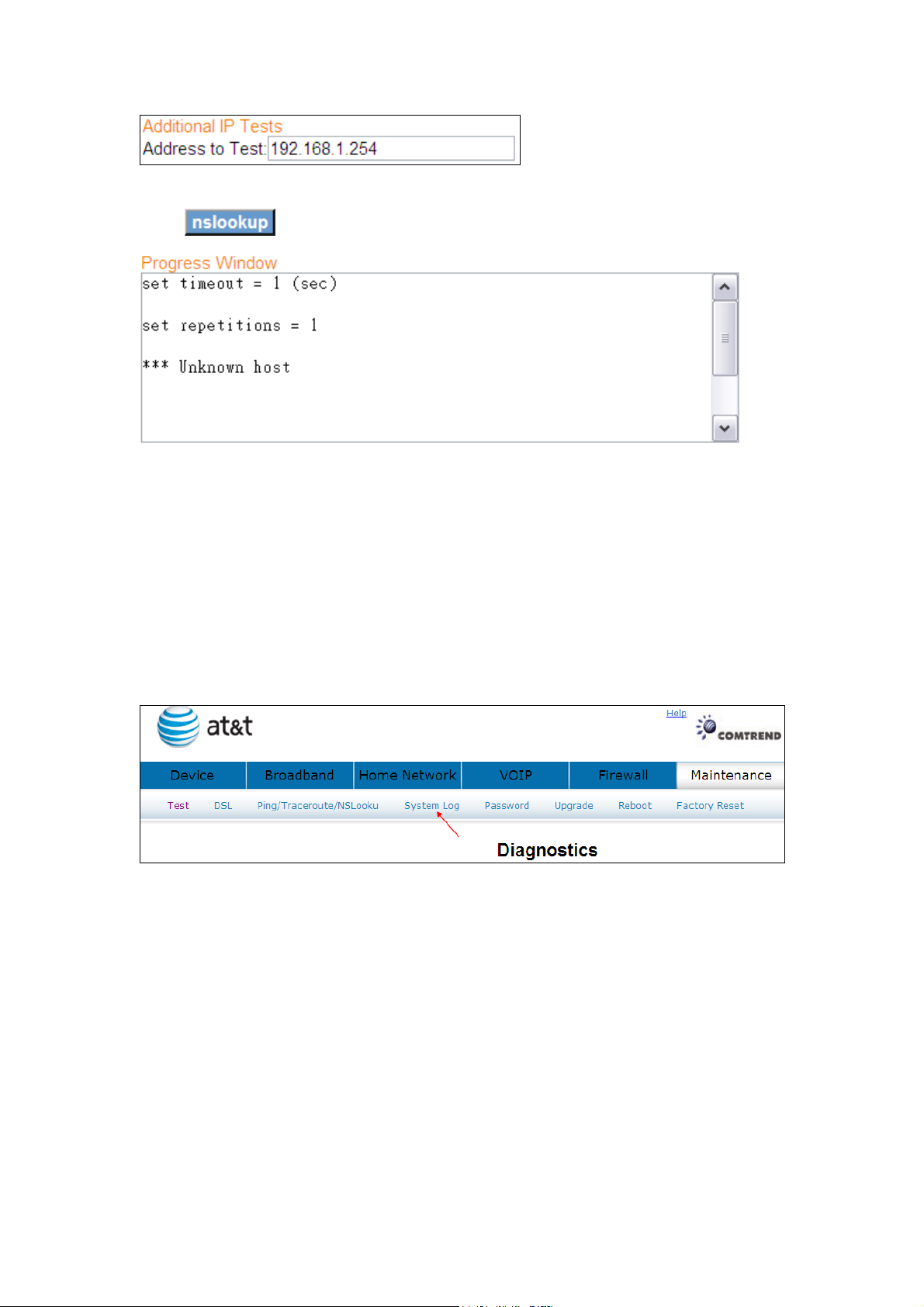
Click to lookup the name server of an IP address.
9.4 System Log
The System Log option allows you to view the system events log.
Click System Log to bring up the following window.
76
Page 78
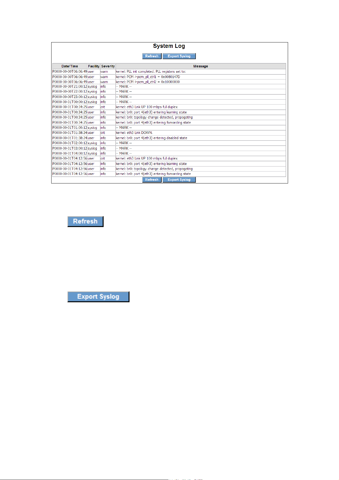
9.4.1 Refresh
Click to update the System Log.
9.4.2 Export Syslog
Click to bring up the following window.
77
Page 79
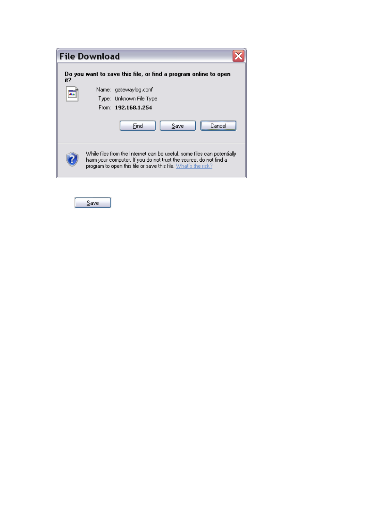
Click to save the system log file.
78
Page 80
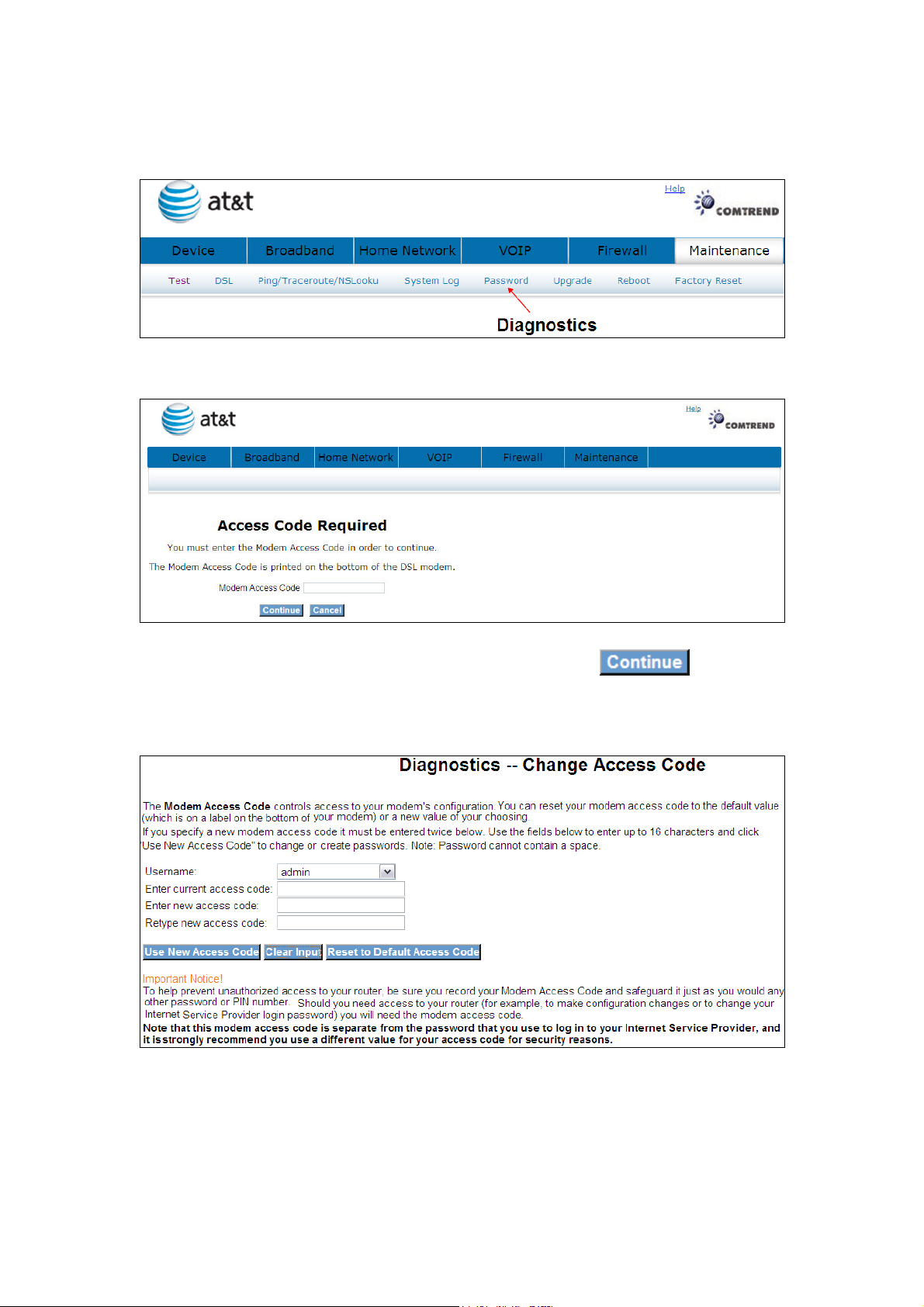
9.5 Password
Click Password to bring up the following window.
Input the access code (which is located ______) and click
The options are shown (on the following page)
79
Page 81
9.5.1 Use New Access Code
Select User, enter the current access code and the new access code. Hen retype the
new access code.
Click
9.5.2 Clear Input
Click to delete what you have entered.
9.5.3 Reset to Default Access Code
Click to reset to default.
80
Page 82
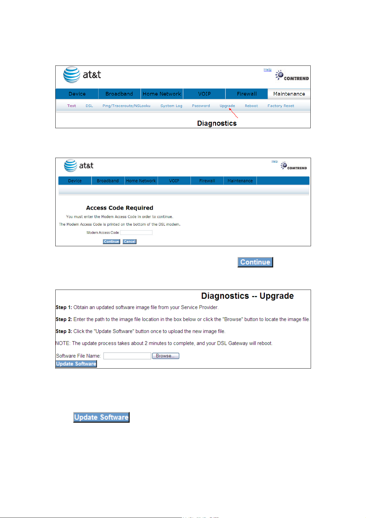
9.6 Upgrade
Click Upgrade to bring up the following window.
Input the access code (which is located ______) and click
The options are shown (on the following page)
Click to start the upgrade process.
81
Page 83
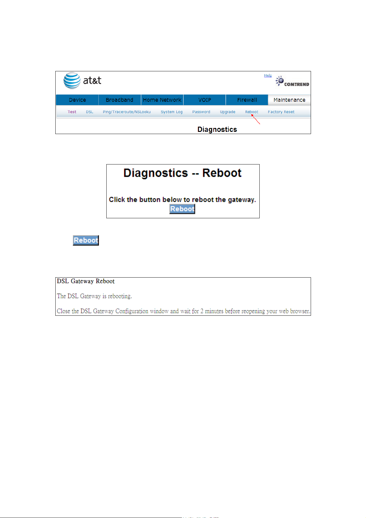
9.7 Reboot
Click to reboot the gateway.
The following window will be displayed.
82
Page 84
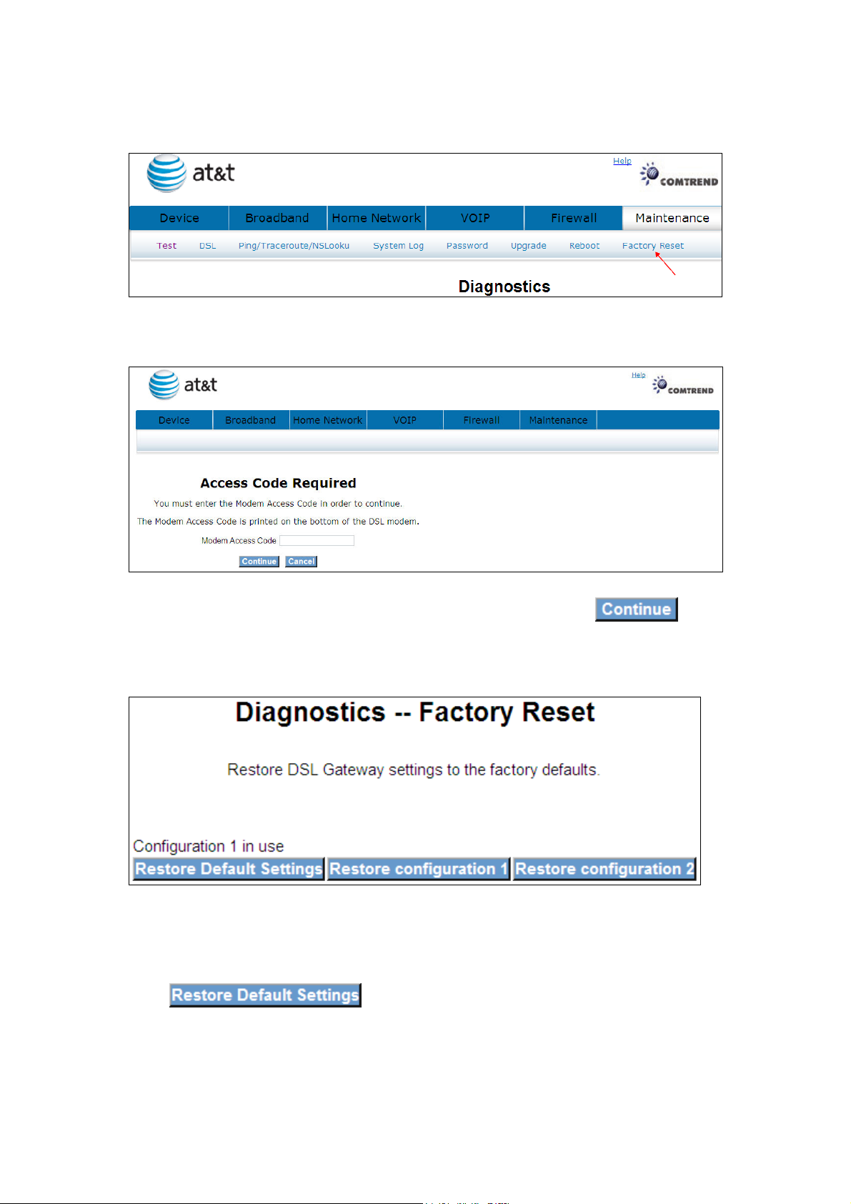
9.8 Factory Reset
Click Factory Reset to bring up the following window.
Input the access code (which is located ______) and click
The options are shown (on the following page)
Click to restore the DSL gateway to the factory
defaults.
83
Page 85
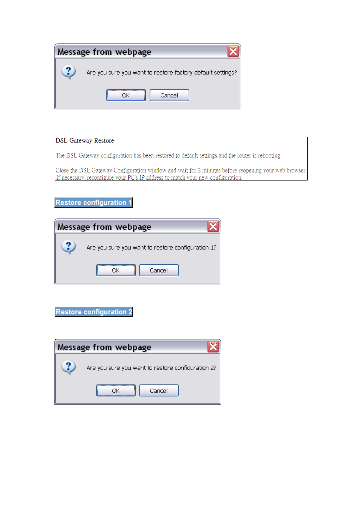
Click OK to confirm.
Click OK to confirm.
84
Page 86

Appendix A: Firewall
Stateful Packet Inspection
Refers to an architecture, where the firewall keeps track of packets on each
connection traversing all its interfaces and makes sure they are valid. This is in
contrast to static packet filtering which only examines a packet based on the
information in the packet header.
Denial of Service attack
Is an incident in which a user or organization is deprived of the services of a
resource they would normally expect to have. Various DoS attacks the device can
withstand are: ARP Attack, Ping Attack, Ping of Death, Land, SYN Attack, Smurf
Attack and Tear Drop.
TCP/IP/Port/Interface filtering rules
These rules help in the filtering of traffic at the Network layer i.e. Layer 3.
When a Routing interface is created "Enable Firewall" must be checked.
Navigate to Advanced Setup -> Security -> IP Filtering, web page.
Outbound Filter: Helps in setting rules to DROP packets from the LAN
interface. By default if Firewall is Enabled all IP traffic from LAN is allowed. By
setting up one or more filters, particular packet types coming from the LAN can be
dropped.
Filter Name: User defined Filter Name.
Protocol: Can take on any values from: TCP/UDP, TCP, UDP or ICMP
Source IP Address/Source Subnet Mask: Packets with the particular “Source IP
Address/Source Subnet Mask" combination will be dropped.
Source Port: This can take on either a single port number or a range of port
numbers. Packets having a source port equal to this value or falling within the range
of port numbers (portX : portY) will be dropped.
Destination IP Address/Destination Subnet Mask: Packets with the particular
"Destination IP Address/Destination Subnet Mask" combination will be dropped.
85
Page 87

Destination Port: This can take on either a single port number or a range
of port numbers. Packets having a destination port equal to this value or falling
within the range of port numbers (portX : portY) will be dropped.
Examples:
1. Filter Name : Out_Filter1
Protocol : TCP
Source Address : 192.168.1.45
Source Subnet Mask : 255.255.255.0
Source Port : 80
Dest. Address : NA
Dest. Sub. Mask : NA
Dest. Port : NA
This filter will Drop all TCP packets coming from LAN with IP Address/Sub. Mask
192.168.1.45/24 having a source port of 80 irrespective of the destination. All other
packets will be Accepted.
2. Filter Name : Out_Filter2
Protocol : UDP
Source Address : 192.168.1.45
Source Subnet Mask : 255.255.255.0
Source Port : 5060:6060
Dest. Address : 172.16.13.4
Dest. Sub. Mask : 255.255.255.0
Dest. Port : 6060:7070
This filter will drop all UDP packets coming from LAN with IP Address/Sub. Mask
192.168.1.45/24 and a source port in the range of 5060 to 6060, destined
to 172.16.13.4/24 and a destination port in the range of 6060 to 7070
Inbound Filter:Helps in setting rules to ACCEPT packets from the WAN interface.
By default all incoming IP traffic from WAN is Blocked, if the Firewall is Enabled.
By setting up one or more filters, particular packet types coming from the WAN can
be Accepted.
Filter Name: User defined Filter Name.
86
Page 88

Protocol: Can take on any values from: TCP/UDP, TCP, UDP or ICMP
Source IP Address/Source Subnet Mask: Packets with the particular "Source IP
Address/Source Subnet Mask" combination will be accepted.
Source Port: This can take on either a single port number or a range of port
numbers. Packets having a source port equal to this value or falling within the range
of port numbers (portX : portY) will be accepted.
Destination IP Address/Destination Subnet Mask: Packets with the particular
"Destination IP Address/Destination Subnet Mask" combination will be accepted.
Destination Port: This can take on either a single port number or a range of port
numbers. Packets having a destination port equal to this value or falling within the
range of port numbers(portX : portY) will be accepted.
The WAN interface on which these rules apply needs to be selected by the user.
Examples:
1. Filter Name : In_Filter1
Protocol : TCP
Source Address : 210.168.219.45
Source Subnet Mask : 255.255.0.0
Source Port : 80
Dest. Address : NA
Dest. Sub. Mask : NA
Dest. Port : NA
Selected WAN interface: mer_0_35/nas_0_35
This filter will ACCEPT all TCP packets coming from WAN interface
mer_0_35/nas_0_35 with IP Address/Sub. Mask 210.168.219.45/16 having a
source port of 80 irrespective of the destination. All other incoming packets on this
interface are DROPPED.
87
Page 89

2. Filter Name : In_Filter2
Protocol : UDP
Source Address : 210.168.219.45
Source Subnet Mask : 255.255.0.0
Source Port : 5060:6060
Dest. Address :192.168.1.45
Dest. Sub. Mask : 255.255.255.0
Dest. Port : 6060:7070
This rule will ACCEPT all UDP packets coming from WAN interface
mer_0_35/nas_0_35 with IP Address/Sub. Mask 210.168.219.45/16 and a
source port in the range of 5060 to 6060, destined to 192.168.1.45/24 and a
destination port in the range of 6060 to 7070. All other incoming packets on this
interface are DROPPED.
88
Page 90

Appendix B: Pin Assignments
Line port (RJ14)
Pin Definition Pin Definition
1 - 4 ADSL_TIP1
2 ADSL_TIP2 5 ADSL_RING2
3 ADSL_RING1 6 -
LAN Port (RJ45)
Pin Definition Pin Definition
1 Transmit data+ 5 NC
2 Transmit data- 6 Receive data-
3 Receive data+ 7 NC
4 NC 8 NC
89
Page 91

Appendix C: Specifications
Rear Panel
RJ-14 X1 for ADSL2+ bonded, RJ-45 X 4 for LAN, Reset Button X 1,
WPS button x1, WIFI button x1 Wi-Fi Antenna x 1
ADSL
ADSL standard ITU-T G.992.5, ITU-T G.992.3, ITU-T G.992.1,
ANSI T1.413 Issue 2AnnexM
ADSL2 Bonded Downstream : 48 Mbps Upstream : 2.6 Mbps
ADSL2+ Bonded Downstream : 48 Mbps Upstream : 2.6 Mbps
ADSL2+ non-Bonded Downstream : 24 Mbps Upstream : 1.3 Mbps
ADSL2 non-Bonded Downstream : 12 Mbps Upstream : 1.3 Mbps
G.DMT Downstream : 8Mbps Upstream : 832kbps
LAN
Standard IEEE 802.3, IEEE 802.3u
10/100 BaseT Auto-sense
MDI/MDX support Yes
Wireless
Standard IEEE802.11b/g/n, backward compatible with 802.11b
Encryption 64, 128-bit Wired Equivalent Privacy (WEP) Data Encryption
Channels 11 Channels (US, Canada)
Data Rate Up to 300Mbps
BSSID Multiple
WPA Yes
WPA2 Yes
WEP Yes
WDS Yes
IEEE 802.1x Yes
10,25,50,100mW@22MHz channel bandwidth output power level can be
90
Page 92

selected according to the environment
Static route, RIP, and RIPv2, NAT/PAT, DHCP Server/DHCP Relay, DNS Relay, ARP
ATM Attributes
RFC 2364 (PPPoA), RFC 2684 (RFC 1483) Bridge/Route; RFC 2516 (PPPoE);
RFC 1577 (IPoA)
Support PVCs 16
AAL type AAL5
ATM service class UBR/CBR/VBR-rt/VBR-nrt
ATM UNI support UNI3.1/4.0
OAM F4/F5 Yes
Management
SNMP, Telnet, Web-based management, Configuration backup and restoration
Software upgrade via HTTP, TFTP server, or FTP server
Supports TR-069/TR-098/TR-111 for Remote Management
Bridge Functions
Transparent bridging and learning IEEE 802.1d
VLAN support Yes
Spanning Tree Algorithm Yes
IGMP Proxy Yes
IGMP Snooping Yes
Voice
SIP: RFC 3261
Codec: G.711, G.723.1, G.726, G.729ab
RTP: RFC 1889
SDP: RFC 2327
Caller ID: ETSI based
Routing Functions
Security Functions
Authentication protocols PAP, CHAP,
TCP/IP/Port filtering rules, Port triggering/Forwarding, Packet and MAC address
filtering, SSH
91
Page 93

S Supported for USB driver
Windows 2000/XP/ME/98SE
Application Passthrough
PPTP, L2TP, IPSec, VoIP, Yahoo messenger, ICQ, RealPlayer, NetMeeting, MSN,
X-box, etc
O
Power Supply
External power adapter 100-240Vac
Environment Condition
Operating temperature 0 ~ 40 degrees Celsius
Relative humidity 5 ~ 95% (non-condensing)
Dimensions
205 mm (W) x 48 mm (H) x 145 mm (D)
Certifications
FCC Part 15 class B, FCC Part 68, CE
Kit Weight
Kit 0.98 KG
NOTE: Specifications are subject to change without notice
92
Page 94

Appendix D: SSH Client
Linux OS comes with ssh client. Microsoft Windows does not have ssh client but
there is a public domain one “putty” that you can download.
http://www.chiark.greenend.org.uk/~sgtatham/putty/download.html
To access the router using Linux ssh client:
From LAN: Use the router WEB UI to enable SSH access from LAN.
(default is enabled)
type: ssh -l admin 192.168.1.1
From WAN: In the router, use WEB UI to enable SSH access from WAN.
type: ssh -l support
router-WAN-ip-address
To access the router using Windows putty ssh client:
From LAN: Use the router WEB UI to enable SSH access from LAN
(default is enabled)
type: putty -ssh -l admin 192.168.1.1
From WAN: In the router, use WEB UI to enable SSH access from WAN.
type: putty -ssh -l support
router-WAN-ip-address
93
 Loading...