


VR-3060u, VR-3060
Wireless Gateway
User Manual
261099-038 |
Version A1.0, December 22, 2015 |

Preface
This manual provides information related to the installation and operation of this device. The individual reading this manual is presumed to have a basic understanding of telecommunications terminology and concepts.
If you find the product to be inoperable or malfunctioning, please contact technical support for immediate service by email at INT-support@comtrend.com
For product update, new product release, manual revision, or software upgrades, please visit our website at http://www.comtrend.com
Important Safety Instructions
With reference to unpacking, installation, use, and maintenance of your electronic device, the following basic guidelines are recommended:
•Do not use or install this product near water, to avoid fire or shock hazard. For example, near a bathtub, kitchen sink or laundry tub, or near a swimming pool. Also, do not expose the equipment to rain or damp areas (e.g. a wet basement).
•Do not connect the power supply cord on elevated surfaces. Allow it to lie freely. There should be no obstructions in its path and no heavy items should be placed on the cord. In addition, do not walk on, step on, or mistreat the cord.
•Use only the power cord and adapter that are shipped with this device.
•To safeguard the equipment against overheating, make sure that all openings in the unit that offer exposure to air are not blocked.
•Avoid using a telephone (other than a cordless type) during an electrical storm. There may be a remote risk of electric shock from lightening. Also, do not use the telephone to report a gas leak in the vicinity of the leak.
•Never install telephone wiring during stormy weather conditions.
CAUTION:
To reduce the risk of fire, use only No. 26 AWG or larger telecommunication line cord.
Always disconnect all telephone lines from the wall outlet before servicing or disassembling this equipment.
WARNING
Disconnect the power line from the device before servicing.
Power supply specifications are clearly stated in Appendix C -
Specifications.
1

FCC & ISED
User Information
Any changes or modifications not expressly approved by the party responsible for compliance could void your authority to operate the equipment.
Aucune modification apportée à l’appareil par l’utilisateur, quelle qu’en soit la nature. Tout changement ou modification peuvent annuler le droit d’utilisation de l’appareil par l’utilisateur.
Note: This equipment has been tested and found to comply with the limits for a Class B digital device, pursuant to part 15 of the FCC Rules. These limits are designed to provide reasonable protection against harmful interference in a residential installation. This equipment generates, uses and can radiate radio frequency energy and, if not installed and used in accordance with the instructions, may cause harmful interference to radio communications. However, there is no guarantee that interference will not occur in a particular installation. If this equipment does cause harmful interference to radio or television reception, which can be determined by turning the equipment off and on, the user is encouraged to try to correct the interference by one or more of the following measures:
—Reorient or relocate the receiving antenna.
—Increase the separation between the equipment and receiver.
—Connect the equipment into an outlet on a circuit different from that to which the
receiver is connected.
—Consult the dealer or an experienced radio/TV technician for help.
This Class B digital apparatus complies with Canadian ICES-003.
To reduce potential radio interference to other users, the antenna type and its gain should be so chosen that the equivalent isotropically radiated power (e.i.r.p.) is not more than that permitted for successful communication.
This device complies with Industry Canada licence-exempt RSS standard(s).
Operation is subject to the following two conditions:
1.This device may not cause interference, and
2.This device must accept any interference, including interference that may cause undesired operation of the device.
Cet appareil numérique de la classe B est conforme à la norme NMB-003 Canada.
Pour réduire le risque d’interférence aux autres utilisateurs, le type d’antenne et son gain doivent être choisies de façon que la puissance isotrope rayonnée équivalente (PIRE) ne dépasse pas ce qui est nécessaire pour une communication réussie.
Cet appareil est conforme à la norme RSS Industrie Canada exempts de licence norme(s). Son fonctionnement est soumis aux deux conditions suivantes:
1.Cet appareil ne peut pas provoquer d’interférences et
2.Cet appareil doit accepter toute interférence, y compris les interférences qui peuvent causer un mauvais fonctionnement du dispositif.
2

Radiation Exposure
FCC ID: L9VVR3060U
IC: 4013A-VR3060U
US: 5SYDL01ANL3240U
REN: 0.1A
FCC
1.This Transmitter must not be colocated or operating in conjunction with any other antenna or transmitter.
2.This equipment complies with FCC RF radiation exposure limits set forth for an uncontrolled environment. This
equipment should be installed and operated with a minimum distance of 20 centimeters between the radiator and your
body.
ISED
This device complies with the ISED radiation exposure limit set forth for an uncontrolled environment. This device should be installed and operated with minimum distance 20cm between the radiator & your body. This transmitter must not be co-located or operating in conjunction with any other antenna or transmitter.
Cet équipement est conforme avec l'exposition aux radiations ISED définies pour un environnement non contrôlé. Cet équipement doit être installé et utilisé à une distance minimum de 20 cm entre le radiateur et votre corps. Cet émetteur ne doit pas être co-localisées ou opérant en conjonction avec une autre antenne ou transmetteur.
Operations in the 5.15-5.25Ghz band are restricted to indoor usage only.
Le fonctionnement sur la bande 5,15–5,25Ghz est limité à une utilisation intérieure uniquement.
This radio transmitter (identify the device by certification number) has been approved by Industry Canada to operate with the antenna types listed below with the maximum permissible gain indicated. Antenna types not included in this list, having a gain greater than the maximum gain indicated for that type, are strictly prohibited for use with this device.
Model Name: AN2450-64D02BBO Type: External
Gain:
2.4G: 2.5 dBi 5G: 2.5 dBi
Model Name: AN2450-64D03BBO
Type: External
Gain:
3
2.4G: 1.2 dBi 5G: 2.5 dBi
The REN statement is the following:
"The Ringer Equivalence Number (REN) indicates the maximum number of devices allowed to be connected to a telephone interface. The termination of an interface may consist of any combination of devices subject only to the requirement that the sum of the RENs of all the devices not exceed five."
Copyright
Copyright©2015 Comtrend Corporation. All rights reserved. The information contained herein is proprietary to Comtrend Corporation. No part of this document may be translated, transcribed, reproduced, in any form, or by any means without prior written consent of Comtrend Corporation.
This program is free software: you can redistribute it and/or modify it under the terms of the GNU General Public License as published by the Free Software Foundation, either version 3 of the License, or (at your option) any later version.
This program is distributed in the hope that it will be useful, but WITHOUT ANY WARRANTY; without even the implied warranty of MERCHANTABILITY or FITNESS FOR A PARTICULAR PURPOSE. See the GNU General Public License for more details.
You should have received a copy of the GNU General Public License along with this program. If not, see http://www.gnu.org/licenses/
NOTE: This document is subject to change without notice.
Protect Our Environment
This symbol indicates that when the equipment has reached the end of its useful life, it must be taken to a recycling centre and processed separate from domestic waste.
The cardboard box, the plastic contained in the packaging, and the parts that make up this router can be recycled in accordance with regionally established regulations. Never dispose of this electronic equipment along with your household waste; you may be subject to penalties or sanctions under the law. Instead, please be responsible and ask for disposal instructions from your local government.
4

Table of Contents |
|
|
CHAPTER 1 INTRODUCTION........................................................................................................... |
8 |
|
CHAPTER 2 INSTALLATION............................................................................................................. |
9 |
|
2.1 HARDWARE SETUP........................................................................................................................... |
9 |
|
2.2 LED INDICATORS .......................................................................................................................... |
11 |
|
CHAPTER 3 WEB USER INTERFACE............................................................................................ |
13 |
|
3.1 DEFAULT SETTINGS ....................................................................................................................... |
13 |
|
3.2 IP CONFIGURATION........................................................................................................................ |
14 |
|
3.3 LOGIN PROCEDURE........................................................................................................................ |
16 |
|
CHAPTER 4 DEVICE INFORMATION........................................................................................... |
18 |
|
4.1 WAN ............................................................................................................................................. |
|
20 |
4.2 STATISTICS..................................................................................................................................... |
21 |
|
4.2.1 |
LAN Statistics ................................................................................................................. |
21 |
4.2.2 |
WAN Service ................................................................................................................... |
22 |
4.2.3 |
XTM Statistics................................................................................................................. |
23 |
4.2.4 |
xDSL Statistics................................................................................................................ |
24 |
4.3 ROUTE ........................................................................................................................................... |
|
29 |
4.4 ARP............................................................................................................................................... |
|
30 |
4.5 DHCP ........................................................................................................................................... |
|
30 |
4.6 NAT SESSION ................................................................................................................................ |
32 |
|
4.7 IGMP INFO.................................................................................................................................... |
33 |
|
4.8 IPV6 .............................................................................................................................................. |
|
34 |
4.8.1 IPv6 Info ................................................................................................................................ |
34 |
|
4.8.2 IPv6 Neighbor ....................................................................................................................... |
35 |
|
4.8.3 IPv6 Route ............................................................................................................................. |
36 |
|
4.9 CPU & MEMORY........................................................................................................................... |
37 |
|
4.10 NETWORK MAP ........................................................................................................................... |
38 |
|
4.11 WIRELESS .................................................................................................................................... |
38 |
|
4.11.1 Station Info........................................................................................................................... |
38 |
|
4.11.2 Site Survey............................................................................................................................ |
40 |
|
CHAPTER 5 BASIC SETUP............................................................................................................... |
42 |
|
5.1 WAN SETUP ................................................................................................................................... |
43 |
|
5.1.1 WAN Service Setup ................................................................................................................ |
44 |
|
5.2 NAT .............................................................................................................................................. |
|
45 |
5.2.1 |
Virtual Servers ................................................................................................................ |
45 |
5.2.2 |
Port Triggering ............................................................................................................... |
47 |
5.2.3 |
DMZ Host ....................................................................................................................... |
49 |
5.2.4 |
IP Address Map............................................................................................................... |
50 |
5.2.5 |
ALG/Pass-Through ......................................................................................................... |
51 |
5.3 LAN.............................................................................................................................................. |
|
52 |
5.3.1 LAN IPv6 Autoconfig............................................................................................................. |
55 |
|
5.3.2 Static IP Neighbor ................................................................................................................. |
58 |
|
5.3.3 UPnP ..................................................................................................................................... |
59 |
|
5.4 WIRELESS...................................................................................................................................... |
60 |
|
5.4.1 Basic 5GHz............................................................................................................................ |
60 |
|
5.4.2 Security 5GHz........................................................................................................................ |
62 |
|
5.4.3 Basic 2.4GHz......................................................................................................................... |
65 |
|
5.4.4 Security 2.4GHz..................................................................................................................... |
67 |
|
5.5 PARENTAL CONTROL ..................................................................................................................... |
70 |
|
5.5.1 |
Time Restriction.............................................................................................................. |
70 |
5.5.2 |
URL Filter....................................................................................................................... |
71 |
5.6 HOME NETWORKING...................................................................................................................... |
73 |
|
5.6.1 Print Server ........................................................................................................................... |
73 |
|
5.6.2 DLNA..................................................................................................................................... |
73 |
|
5.6.3 Storage Service...................................................................................................................... |
74 |
|
5.6.4 USB Speed ............................................................................................................................. |
75 |
|
|
|
5 |

CHAPTER 6 ADVANCED SETUP..................................................................................................... |
76 |
|
6.1 AUTO-DETECTION SETUP ............................................................................................................... |
76 |
|
6.2 SECURITY ...................................................................................................................................... |
81 |
|
6.2.1 |
IP Filtering ..................................................................................................................... |
81 |
6.2.2 |
MAC Filtering................................................................................................................. |
85 |
6.3 QUALITY OF SERVICE (QOS).......................................................................................................... |
87 |
|
6.3.1 |
QoS Queue...................................................................................................................... |
88 |
6.3.1.1 |
QoS Queue Configuration .............................................................................................. |
88 |
6.3.1.2 |
Wlan Queue .................................................................................................................... |
92 |
6.3.2 |
QoS Classification .......................................................................................................... |
93 |
6.3.3 |
QoS Port Shaping ........................................................................................................... |
95 |
6.4 ROUTING ....................................................................................................................................... |
96 |
|
6.4.1 |
Default Gateway............................................................................................................. |
96 |
6.4.2 |
Static Route..................................................................................................................... |
97 |
6.4.3 |
Policy Routing ................................................................................................................ |
98 |
6.4.4 |
RIP.................................................................................................................................. |
99 |
6.5 DNS ............................................................................................................................................ |
|
100 |
6.5.1 |
DNS Server ................................................................................................................... |
100 |
6.5.2 |
Dynamic DNS ............................................................................................................... |
101 |
6.5.3 |
DNS Entries .................................................................................................................. |
102 |
6.5.4 |
DNS Proxy/Relay .......................................................................................................... |
103 |
6.6 DSL............................................................................................................................................. |
|
104 |
6.7 INTERFACE GROUPING................................................................................................................. |
106 |
|
6.8 IP TUNNEL................................................................................................................................... |
109 |
|
6.8.1 IPv6inIPv4........................................................................................................................... |
109 |
|
6.8.2 IPv4inIPv6........................................................................................................................... |
110 |
|
6.9 CERTIFICATE................................................................................................................................ |
111 |
|
6.9.1 |
Local............................................................................................................................. |
111 |
6.9.2 |
Trusted CA .................................................................................................................... |
113 |
6.10 POWER MANAGEMENT .............................................................................................................. |
114 |
|
6.11 MULTICAST................................................................................................................................ |
115 |
|
6.12 WIRELESS.................................................................................................................................. |
117 |
|
6.12.1 Basic 5GHz........................................................................................................................ |
117 |
|
6.12.2 Security 5GHz.................................................................................................................... |
119 |
|
6.12.3 WPS 5GHz......................................................................................................................... |
122 |
|
6.12.4 MAC Filter 5GHz .............................................................................................................. |
125 |
|
6.12.5 Wireless Bridge.................................................................................................................. |
126 |
|
6.12.6 Advanced 5GHz ................................................................................................................. |
127 |
|
6.12.7 Basic 2.4GHz..................................................................................................................... |
131 |
|
6.12.8 Security 2.4GHz................................................................................................................. |
133 |
|
6.12.9 WPS 2.4GHz ...................................................................................................................... |
136 |
|
6.12.10 MAC Filter 2.4GHz ......................................................................................................... |
139 |
|
6.12.11 Wireless Bridge 2.4GHz................................................................................................... |
141 |
|
6.12.12 Advanced 2.4GHz ............................................................................................................ |
142 |
|
CHAPTER 7 DIAGNOSTICS........................................................................................................... |
145 |
|
7.1 DIAGNOSTICS – INDIVIDUAL TESTS ............................................................................................. |
145 |
|
7.2 ETHERNET OAM ......................................................................................................................... |
146 |
|
7.3 UPTIME STATUS ........................................................................................................................... |
148 |
|
7.4 PING ............................................................................................................................................ |
|
149 |
7.5 TRACE ROUTE ............................................................................................................................. |
150 |
|
CHAPTER 8 MANAGEMENT ........................................................................................................ |
151 |
|
8.1 SETTINGS..................................................................................................................................... |
151 |
|
8.1.1 |
Backup Settings............................................................................................................. |
151 |
8.1.2 |
Update Settings............................................................................................................. |
152 |
8.1.3 |
Restore Default ............................................................................................................. |
152 |
8.2 SYSTEM LOG ............................................................................................................................... |
154 |
|
8.3 SNMPAGENT ............................................................................................................................. |
156 |
|
8.4 TR-069 CLIENT ........................................................................................................................... |
157 |
|
8.5 INTERNET TIME ........................................................................................................................... |
159 |
|
|
|
6 |

8.6 ACCESS CONTROL ....................................................................................................................... |
160 |
|
8.6.1 |
Accounts ........................................................................................................................... |
160 |
8.6.2 |
Services............................................................................................................................. |
162 |
8.6.3 |
IP Address......................................................................................................................... |
163 |
8.7 WAKE-ON-LAN........................................................................................................................... |
164 |
|
8.8 UPDATE SOFTWARE ..................................................................................................................... |
165 |
|
8.9 REBOOT....................................................................................................................................... |
166 |
|
CHAPTER 9 LOGOUT..................................................................................................................... |
167 |
|
APPENDIX A - FIREWALL ............................................................................................................. |
168 |
|
APPENDIX B - PIN ASSIGNMENTS.............................................................................................. |
171 |
|
APPENDIX C – SPECIFICATIONS................................................................................................ |
172 |
|
APPENDIX D - SSH CLIENT .......................................................................................................... |
174 |
|
APPENDIX E - PRINTER SERVER................................................................................................ |
175 |
|
APPENDIX F - CONNECTION SETUP.......................................................................................... |
181 |
|
7

Chapter 1 Introduction
VR-3060 is a Multi-DSL solution for high-performance Internet access. In addition, VR-3060 supports high power (400mw/26 dBm) dual bands (802.11n 2.4GHz & 802.11ac 5GHz) to create a large Wi-Fi footprint for the most seamless video experience as well as blazing fast data speed and a toll-quality voice experience.
8

Chapter 2 Installation
2.1 Hardware Setup
Follow the instructions below to complete the hardware setup.
Non-stackable
This device is not stackable – do not place units on top of each other, otherwise damage could occur.
BACK PANEL
The figure below shows the back panel of the device.
Power ON
Press the power button to the OFF position (OUT). Connect the power adapter to the power port. Attach the power adapter to a wall outlet or other AC source. Press the power button to the ON position (IN). If the Power LED displays as expected then the device is ready for setup (see section 2.2 LED Indicators).
Caution 1: If the device fails to power up, or it malfunctions, first verify that the power cords are connected securely and then power it on again. If the problem persists, contact technical support.
Caution 2: Before servicing or disassembling this equipment, disconnect all power cords and telephone lines from their outlets.
Reset Button
Restore the default parameters of the device by pressing the Reset button for 10 seconds. After the device has rebooted successfully, the front panel should display as expected (see section 2.2 LED Indicators for details).
NOTE: If pressed down for more than 60 seconds, the VR-3060 will go into a firmware update state (CFE boot mode). The firmware can then be updated using an Internet browser pointed to the default IP address.
9
ETH WAN PORT
This port has the same features as the LAN ports described below with additional Ethernet WAN functionality.
Ethernet (LAN) Ports
Use 1000-BASE-T RJ-45 cables to connect up to four network devices to a Gigabit LAN, or 10/100BASE-T RJ-45 cables for standard network usage. These ports are auto-sensing MDI/X; so either straight-through or crossover cable can be used.
USB Host Port (Type A)
This port can be used to connect the router to a printer, or supported USB devices.
DSL Port
Connect to an ADSL2/2+ or VDSL with this RJ11 Port. This device contains a micro filter which removes the analog phone signal. If you wish, you can connect a regular telephone to the same line by using a POTS splitter.
FRONT PANEL
2.4G WiFi On/Off & WPS Button
Press and release the WiFi-WPS button to activate WPS for the 2.4GHz WiFi interface (make sure the WPS is enabled in Wireless->2.4GHz->Security page). Press and hold WiFi-WPS button more than 10 seconds to enable/disable 2.4GHz WiFi.
5G WiFi On/Off & WPS Button
Press and release the WiFi-WPS button to activate WPS for the 5GHz WiFi interface (make sure the WPS is enabled in Wireless->5GHz->Security page).
Press and hold WiFi-WPS button more than 10 seconds to enable/disable 5GHz WiFi.
10

2.2 LED Indicators
The front panel LED indicators are shown below and explained in the following table. This information can be used to check the status of the device and its connections.
|
LED |
|
Color |
|
|
Mode |
|
Function |
|
|
|
GREEN |
|
|
On |
The device is powered up. |
|
|
|
|
|
|
|
|
|
|
|
|
|
|
|
Off |
|
The device is powered down. |
|
|
|
|
|
|
|
|
||
|
POWER |
|
|
|
|
|
|
POST (Power On Self Test) failure or other |
|
|
|
RED |
|
|
On |
|
malfunction. A malfunction is any error of internal |
|
|
|
|
|
|
sequence or state that will prevent the device from |
||
|
|
|
|
|
|
|
|
|
|
|
|
|
|
|
|
|
connecting to the DSLAM or passing customer data. |
|
|
|
|
|
|
On |
WAN is connected in 1000 Mbps. |
|
|
|
|
|
|
|
|
|
|
|
|
|
GREEN |
|
|
Off |
|
Ethernet WAN is not connected. |
|
|
|
|
|
|
|
|
|
|
ETH WAN |
|
|
|
|
Blink |
|
In TX/RX over 1000 Mbps |
|
|
|
|
|
On |
|
Ethernet is connected in 10/100 Mbps. |
|
|
|
|
|
|
|
|
||
|
|
|
|
|
|
|
|
|
|
|
|
ORANGE |
|
|
Off |
|
Ethernet WAN is not connected. |
|
|
|
|
|
|
|
|
|
|
|
|
|
|
|
Blink |
|
In TX/RX over 10/100 Mbps. |
|
|
|
|
|
|
On |
|
Ethernet is connected at 1000 Mbps. |
|
|
|
|
|
|
|
|
|
|
|
|
GREEN |
|
|
Off |
|
Ethernet is not connected. |
|
|
|
|
|
|
|
|
|
|
ETH 4 to 1 |
|
|
|
|
Blink |
|
In TX/RX over 1000 Mbps. |
|
|
|
|
|
On |
|
Ethernet is connected at 10/100 Mbps. |
|
|
|
|
|
|
|
|
||
|
|
|
|
|
|
|
|
|
|
|
|
ORANGE |
|
|
Off |
|
Ethernet is not connected. |
|
|
|
|
|
|
|
|
|
|
|
|
|
|
|
Blink |
|
In TX/RX over 10/100 Mbps. |
|
|
|
|
|
|
On |
|
WPS(2.4G) WPS enabled and client connected to |
|
|
|
|
|
|
|
|
WLAN. |
|
|
|
|
|
|
|
|
|
|
|
|
GREEN |
|
|
Off |
|
WPS(2.4G) WPS disabled. |
|
|
|
|
|
|
|
|
|
|
|
|
|
|
|
Blink |
|
WPS(2.4G) WPS connection in progress, 120 |
|
WPS |
|
|
|
|
|
|
seconds or until client connected. |
|
|
|
|
|
On |
WPS(5G WPS enabled and client connected to |
||
|
|
|
|
|
|
|||
|
|
|
|
|
|
|
|
WLAN. |
|
|
|
|
|
|
|
|
|
|
|
|
ORANGE |
|
|
Off |
|
WPS(5G) WPS disabled. |
|
|
|
|
|
|
|
|
|
|
|
|
|
|
|
Blink |
WPS(5G) WPS connection in progress, 120 seconds |
|
|
|
|
|
|
|
|
|
or until client connected. |
|
|
|
|
|
|
On |
|
The wireless module is ready. |
|
WiFi |
|
|
|
|
|
|
(i.e. installed and enabled). |
|
|
|
|
|
|
|
|
|
|
|
GREEN |
|
|
Off |
|
The wireless module is not ready. |
|
|
2.4G |
|
|
|
|
|||
|
|
|
|
|
|
(i.e. either not installed or disabled). |
||
|
|
|
|
|
|
|
|
|
|
|
|
|
|
|
|
|
|
|
|
|
|
|
|
Blink |
|
Data transmitting or receiving over WLAN. |
|
|
|
|
|
|
|
11 |
|

|
|
|
|
On |
The wireless module is ready. |
WiFi |
|
|
|
|
(i.e. installed and enabled). |
|
|
|
|
|
|
|
GREEN |
|
Off |
The wireless module is not ready. |
|
5G |
|
|
|||
|
|
|
(i.e. either not installed or disabled). |
||
|
|
|
|
|
|
|
|
|
|
|
|
|
|
|
|
Blink |
Data transmitting or receiving over WLAN. |
|
|
|
|
On |
xDSL Link is established. |
|
|
|
|
|
|
DSL |
|
GREEN |
|
Off |
xDSL Link is not established. |
|
|
|
|
||
|
|
Blink |
The xDSL link is training or some traffic is passing |
||
|
|
|
|
||
|
|
|
|
|
through xDSL. |
|
|
|
|
On |
IP connected and no traffic detected. If an IP or |
|
|
|
|
|
PPPoE session is dropped due to an idle timeout, |
|
|
|
|
|
the light will remain green if an ADSL connection is |
|
|
|
|
|
still present. |
|
|
|
|
|
|
|
|
GREEN |
|
Off |
Modem power off, modem in bridged mode or ADSL |
|
|
|
|
|
connection not present. In addition, if an IP or |
INTERNET |
|
|
|
|
PPPoE session is dropped for any reason, other than |
|
|
|
|
an idle timeout, the light is turned off. |
|
|
|
|
|
|
|
|
|
|
|
|
|
|
|
|
|
Blink |
IP connected and IP Traffic is passing thru the |
|
|
|
|
|
device (either direction) |
|
|
|
|
|
Device attempted to become IP connected and |
|
|
RED |
|
On |
failed (no DHCP response, no PPPoE response, |
|
|
|
PPPoE authentication failed, no IP address from |
||
|
|
|
|
|
|
|
|
|
|
|
IPCP, etc.) |
|
|
|
|
|
|
12

Chapter 3 Web User Interface
This section describes how to access the device via the web user interface (WUI) using an Internet browser such as Internet Explorer (version 5.0 and later).
3.1 Default Settings
The factory default settings of this device are summarized below.
•LAN IP address: 192.168.1.1
•LAN subnet mask: 255.255.255.0
•Administrative access (username: root, password: 12345)
•User access (username: user, password: user)
•Remote (WAN) access (username: support, password: support)
•WLAN access: enabled
Technical Note
During power on, the device initializes all settings to default values. It will then read the configuration profile from the permanent storage section of flash memory. The default attributes are overwritten when identical attributes with different values are configured. The configuration profile in permanent storage can be created via the web user interface or telnet user interface, or other management protocols. The factory default configuration can be restored either by pushing the reset button for more than ten seconds until the power indicates LED blinking or by clicking the Restore Default Configuration option in the Restore Settings screen.
13
3.2 IP Configuration
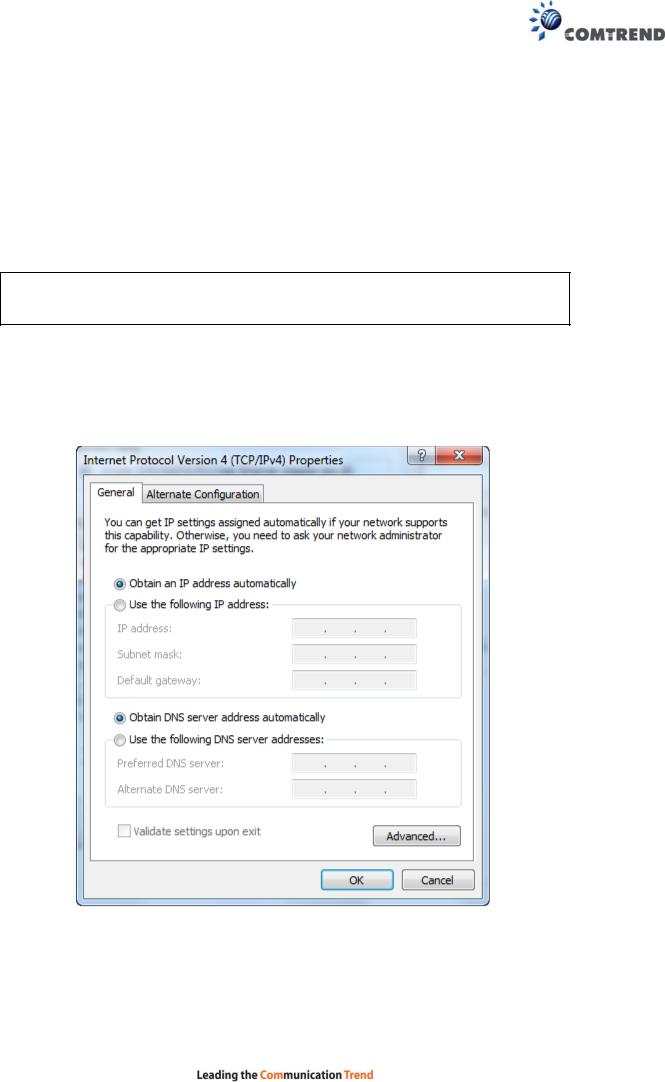
DHCP MODE
When the VR-3060 powers up, the onboard DHCP server will switch on. Basically, the DHCP server issues and reserves IP addresses for LAN devices, such as your PC.
To obtain an IP address from the DCHP server, follow the steps provided below.
NOTE: The following procedure assumes you are running Windows. However, the general steps involved are similar for most operating systems (OS). Check your OS support documentation for further details.
STEP 1: From the Network Connections window, open Local Area Connection (You may also access this screen by double-clicking the Local Area Connection icon on your taskbar). Click the Properties button.
STEP 2: Select Internet Protocol (TCP/IP) and click the Properties button. STEP 3: Select Obtain an IP address automatically as shown below.
STEP 4: Click OK to submit these settings.
If you experience difficulty with DHCP mode, you can try static IP mode instead.
14
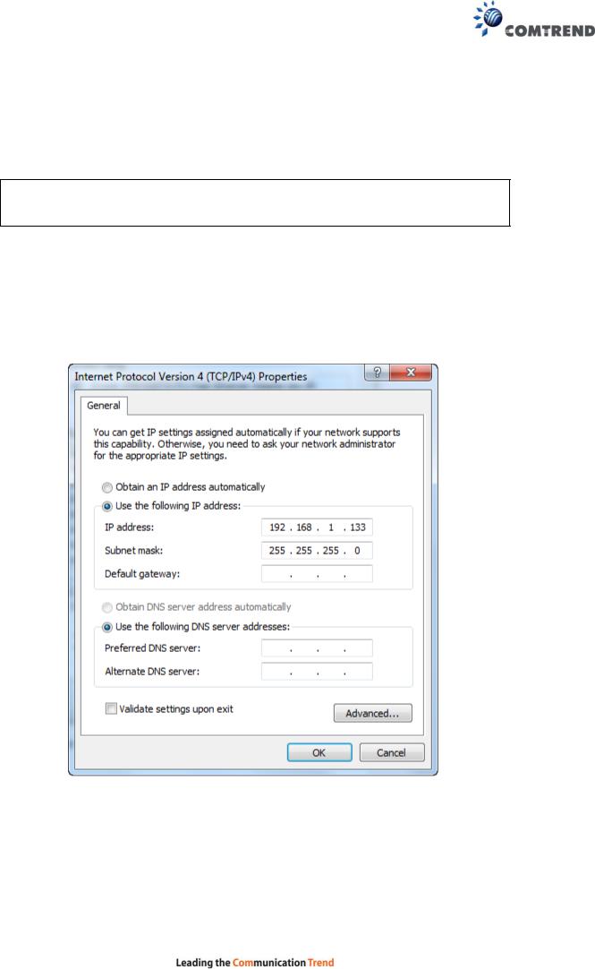
STATIC IP MODE
In static IP mode, you assign IP settings to your PC manually.
Follow these steps to configure your PC IP address to use subnet 192.168.1.x.
NOTE: The following procedure assumes you are running Windows. However, the general steps involved are similar for most operating systems (OS). Check your OS support documentation for further details.
STEP 1: From the Network Connections window, open Local Area Connection (You may also access this screen by double-clicking the Local Area Connection icon on your taskbar). Click the Properties button.
STEP 2: Select Internet Protocol (TCP/IP) and click the Properties button.
STEP 3: Change the IP address to the 192.168.1.x (1<x<255) subnet with subnet mask of 255.255.255.0. The screen should now display as shown below.
STEP 4: Click OK to submit these settings.
15
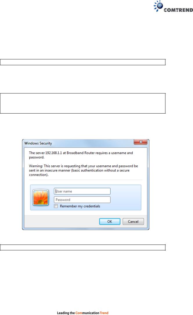
3.3 Login Procedure
Perform the following steps to login to the web user interface.
NOTE: The default settings can be found in section 3.1 Default Settings.
STEP 1: Start the Internet browser and enter the default IP address for the device in the Web address field. For example, if the default IP address is 192.168.1.1, type http://192.168.1.1.
NOTE: For local administration (i.e. LAN access), the PC running the browser must be attached to the Ethernet, and not necessarily to the device. For remote access (i.e. WAN), use the IP address shown on the Device Information screen and login with remote username and password.
STEP 2: A dialog box will appear, such as the one below. Enter the default username and password, as defined in section 3.1 Default Settings.
Click OK to continue.
NOTE: The login password can be changed later (see section 8.6.1 Accounts).
16
STEP 3: After successfully logging in for the first time, you will reach this screen.
You can also reach this page by clicking on the following icon located at the top of the screen.
17
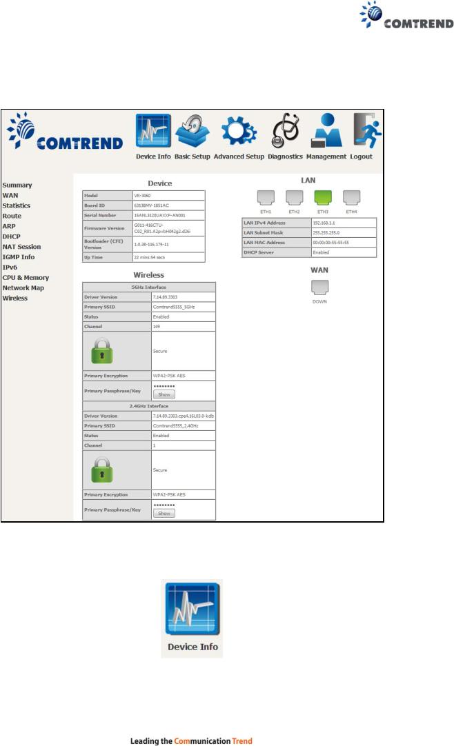
Chapter 4 Device Information
You can reach this page by clicking on the following icon located at the top of the screen.
The web user interface window is divided into two frames, the main menu (on the left) and the display screen (on the right). The main menu has several options and selecting each of these options opens a submenu with more selections.
NOTE: The menu items shown are based upon the configured connection(s) and user account privileges. For example, user account has limited access to configuration modification.
Device Info is the first selection on the main menu so it will be discussed first. Subsequent chapters will introduce the other main menu options in sequence.
The Device Info Summary screen displays at startup.
18
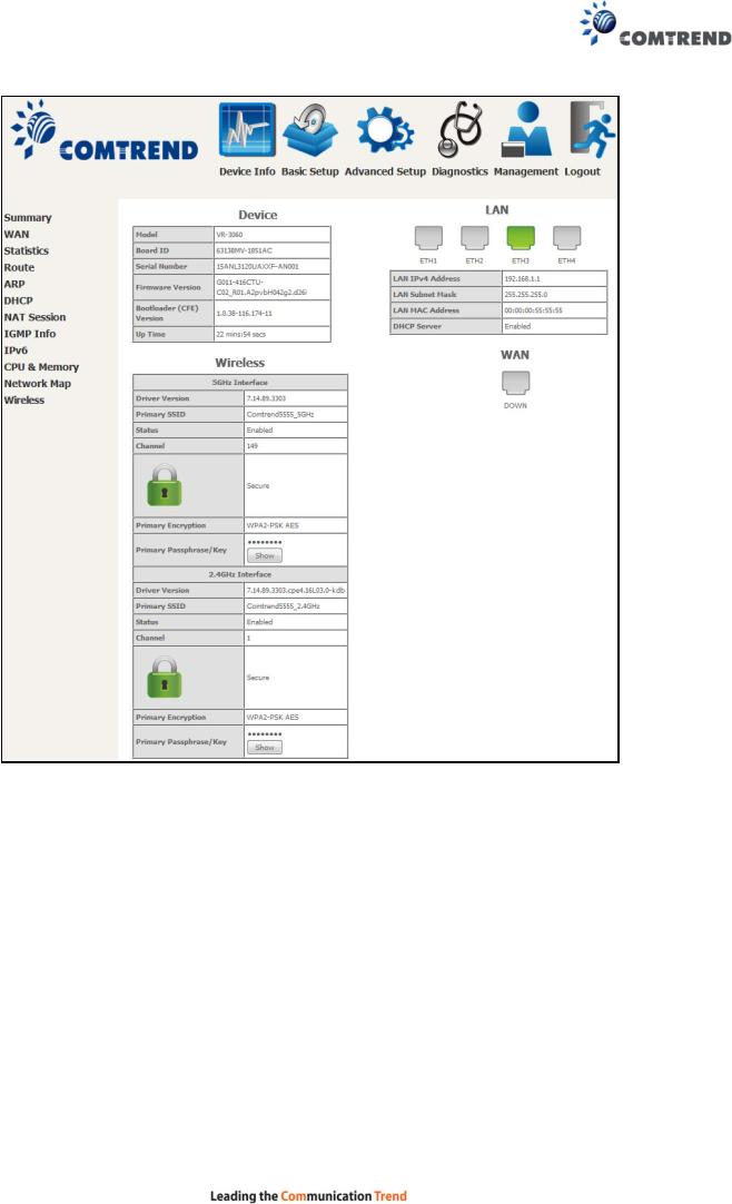
This screen shows hardware, software, IP settings and other related information.
19
4.1 WAN
Select WAN from the Device Info submenu to display the configured PVC(s).
|
Heading |
|
|
Description |
|
|
|
|
|
||
|
Interface |
|
Name of the interface for WAN |
||
|
|
|
|
||
|
Description |
|
Name of the WAN connection |
||
|
|
|
|
||
|
Type |
|
Shows the connection type |
||
|
|
|
|
||
|
VlanMuxId |
|
Shows 802.1Q VLAN ID |
||
|
|
|
|
||
|
IPv6 |
|
Shows WAN IPv6 status |
||
|
|
|
|
||
|
Igmp Pxy |
|
Shows Internet Group Management Protocol (IGMP) |
||
|
|
|
|
proxy status |
|
|
|
|
|
||
|
Igmp Src Enbl |
|
Shows the status of WAN interface used as IGMP source |
||
|
|
|
|
||
|
MLD Pxy |
|
Shows Multicast Listener Discovery (MLD) proxy status |
||
|
|
|
|
||
|
MLD Src Enbl |
|
Shows the status of WAN interface used as MLD source |
||
|
|
|
|
||
|
NAT |
|
Shows Network Address Translation (NAT) status |
||
|
|
|
|
||
|
Firewall |
|
Shows the status of Firewall |
||
|
|
|
|
||
|
Status |
|
Lists the status of DSL link |
||
|
|
|
|
||
|
IPv4 Address |
|
Shows WAN IPv4 address |
||
|
|
|
|
||
|
IPv6 Address |
|
Shows WAN IPv6 address |
||
|
|
|
|
|
|
20
4.2 Statistics
This selection provides LAN, WAN, ATM and xDSL statistics.
NOTE: These screens are updated automatically every 15 seconds. Click Reset Statistics to perform a manual update.
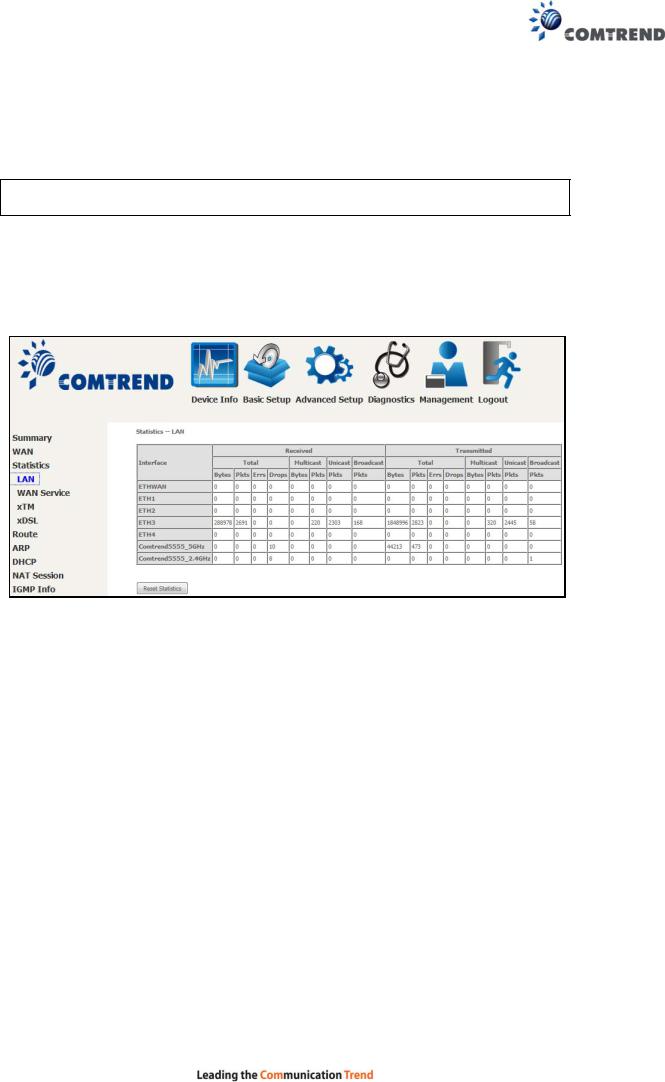
4.2.1LAN Statistics
This screen shows data traffic statistics for each LAN interface.
|
Heading |
|
Description |
|
|
|
|
||
|
Interface |
|
LAN interface(s) |
|
|
|
|
|
|
|
Received/Transmitted: - Bytes |
|
Number of Bytes |
|
|
- Pkts |
|
Number of Packets |
|
|
- Errs |
|
Number of packets with errors |
|
|
- Drops |
|
Number of dropped packets |
|
|
|
|
|
|
21
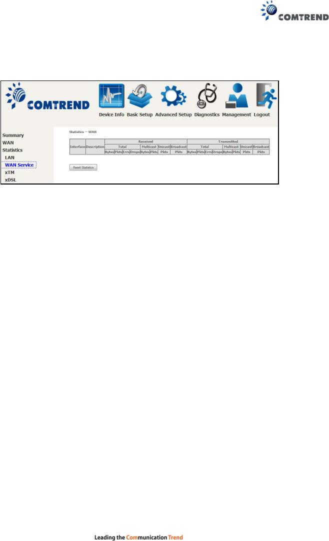
4.2.2WAN Service
This screen shows data traffic statistics for each WAN interface.
|
Heading |
|
|
Description |
|
|
|
|
|
||
|
Interface |
|
|
WAN interfaces |
|
|
|
|
|
|
|
|
Description |
|
|
WAN service label |
|
|
|
|
|
|
|
|
Received/Transmitted - |
Bytes |
|
Number of Bytes |
|
- |
Pkts |
|
Number of Packets |
||
- |
Errs |
|
Number of packets with errors |
||
- |
Drops |
|
Number of dropped packets |
||
|
|
|
|
|
|
22
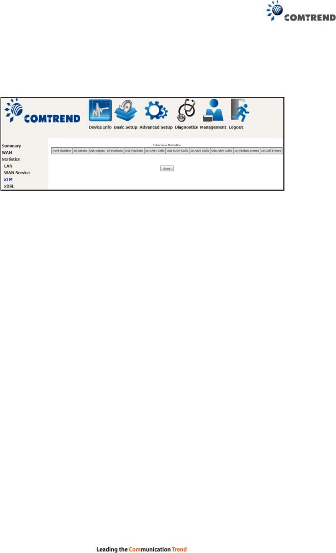
4.2.3XTM Statistics
The following figure shows ATM (Asynchronous Transfer Mode)/PTM (Packet Transfer Mode) statistics.
XTM Interface Statistics
Heading |
Description |
Port Number |
ATM PORT (0-1) |
|
|
In Octets |
Number of octets received over the interface |
|
|
Out Octets |
Number of octets transmitted over the interface |
|
|
In Packets |
Number of packets received over the interface |
|
|
Out Packets |
Number of packets transmitted over the interface |
|
|
In OAM Cells |
Number of OAM Cells received over the interface |
|
|
Out OAM Cells |
Number of OAM Cells transmitted over the interface |
|
|
In ASM Cells |
Number of ASM Cells received over the interface |
|
|
Out ASM Cells |
Number of ASM Cells transmitted over the interface |
|
|
In Packet Errors |
Number of packets in Error |
|
|
In Cell Errors |
Number of cells in Error |
|
|
23

4.2.4xDSL Statistics
The xDSL Statistics screen displays information corresponding to the xDSL type. The two examples below (VDSL & ADSL) show this variation.
VDSL
24
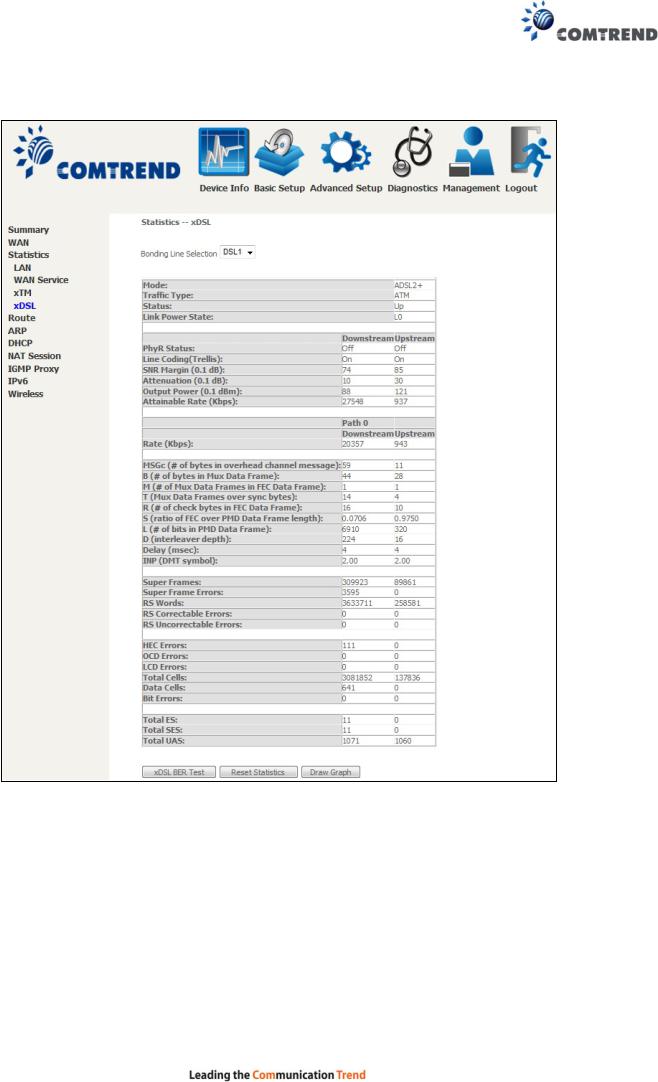
ADSL
Click the Reset Statistics button to refresh this screen.
|
Field |
|
Description |
|
|
|
|
||
|
Mode |
|
VDSL, VDSL2 |
|
|
|
|
|
|
|
Traffic Type |
|
ATM, PTM |
|
|
|
|
|
|
|
Status |
|
Lists the status of the DSL link |
|
|
|
|
|
|
|
Link Power State |
|
Link output power state |
|
|
|
|
|
|
|
phyR Status |
|
Shows the status of PhyR™ (Physical Layer |
|
|
|
|
Re-Transmission) impulse noise protection |
|
|
|
|
|
|
|
|
25 |
|
|

|
Field |
|
Description |
|
|
|
|
||
|
Line Coding (Trellis) |
|
Trellis On/Off |
|
|
|
|
|
|
|
SNR Margin (0.1 dB) |
|
Signal to Noise Ratio (SNR) margin |
|
|
|
|
||
|
Attenuation (0.1 dB) |
Estimate of average loop attenuation in the downstream |
||
|
|
|
direction |
|
|
|
|
|
|
|
Output Power |
|
Total upstream output power |
|
|
(0.1 dBm) |
|
|
|
|
|
|
|
|
|
Attainable Rate (Kbps) |
|
The sync rate you would obtain |
|
|
|
|
|
|
|
Rate (Kbps) |
|
Current sync rates downstream/upstream |
|
|
|
|
|
|
In VDSL mode, the following section is inserted.
MSGc |
Number of bytes in overhead channel message |
|
|
B |
Number of bytes in Mux Data Frame |
|
|
M |
Number of Mux Data Frames in a RS codeword |
|
|
T |
Number of Mux Data Frames in an OH sub-frame |
|
|
R |
Number of redundancy bytes in the RS codeword |
|
|
S |
Number of data symbols the RS codeword spans |
|
|
L |
Number of bits transmitted in each data symbol |
|
|
D |
The interleaver depth |
|
|
I |
The interleaver block size in bytes |
|
|
N |
RS codeword size |
|
|
Delay |
The delay in milliseconds (msec) |
|
|
INP |
DMT symbol |
|
|
|
|
Super Frames |
Total number of super frames |
|
|
Super Frame Errors |
Number of super frames received with errors |
|
|
RS Words |
Total number of Reed-Solomon code errors |
|
|
RS Correctable Errors |
Total Number of RS with correctable errors |
|
|
RS Uncorrectable Errors |
Total Number of RS words with uncorrectable errors |
|
|
|
|
OH Frames |
Total number of OH frames |
|
|
OH Frame Errors |
Number of OH frames received with errors |
|
|
RS Words |
Total number of Reed-Solomon code errors |
|
|
RS Correctable Errors |
Total Number of RS with correctable errors |
|
|
RS Uncorrectable Errors |
Total Number of RS words with uncorrectable errors |
|
|
|
|
HEC Errors |
Total Number of Header Error Checksum errors |
|
|
OCD Errors |
Total Number of Out-of-Cell Delineation errors |
|
|
LCD Errors |
Total number of Loss of Cell Delineation |
|
|
Total Cells |
Total number of ATM cells (including idle + data cells) |
|
|
Data Cells |
Total number of ATM data cells |
|
|
Bit Errors |
Total number of bit errors |
|
|
|
26 |
Total ES |
Total Number of Errored Seconds |
|
|
Total SES |
Total Number of Severely Errored Seconds |
|
|
Total UAS |
Total Number of Unavailable Seconds |
|
|
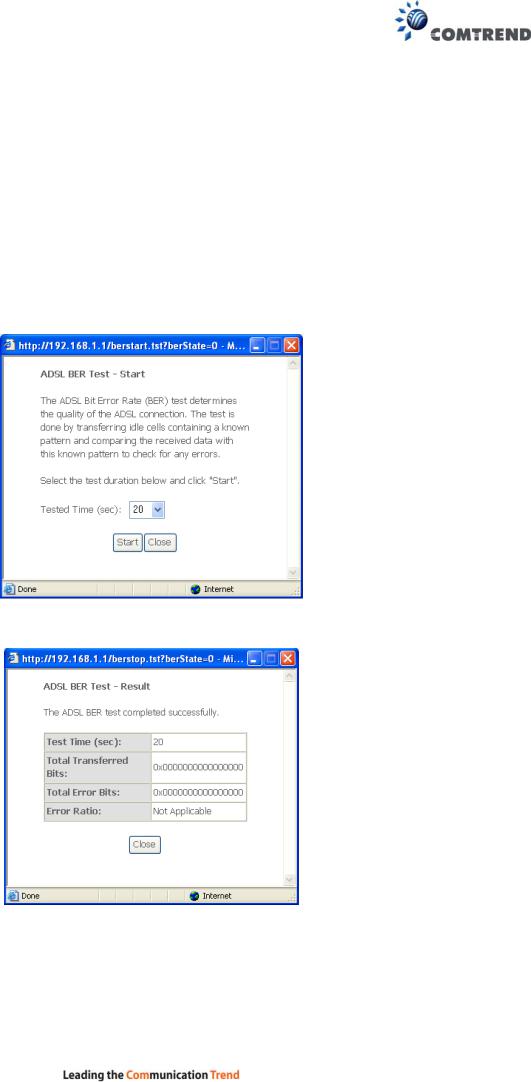
xDSL BER TEST
Click xDSL BER Test on the xDSL Statistics screen to test the Bit Error Rate (BER). A small pop-up window will open after the button is pressed, as shown below.
Click Start to start the test or click Close to cancel the test. After the BER testing is complete, the pop-up window will display as follows.
27
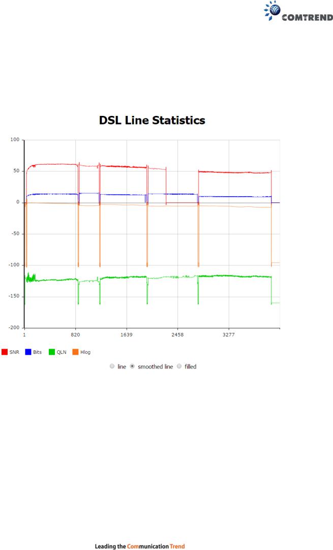
xDSL TONE GRAPH
Click Draw Graph on the xDSL Statistics screen and a pop-up window will display the xDSL statistics graph, including SNR, Bits per tone, QLN and Hlog of the xDSL line connection, as shown below.
28

4.3 Route
Choose Route to display the routes that the VR-3060 has found.
|
Field |
|
|
Description |
|
|
|
|
|
||
|
Destination |
|
Destination network or destination host |
||
|
|
|
|
||
|
Gateway |
|
Next hop IP address |
||
|
|
|
|
||
|
Subnet Mask |
|
Subnet Mask of Destination |
||
|
|
|
|
||
|
Flag |
|
U: route is up |
||
|
|
|
|
!: reject route |
|
|
|
|
|
G: use gateway |
|
|
|
|
|
H: target is a host |
|
|
|
|
|
R: reinstate route for dynamic routing |
|
|
|
|
|
D: dynamically installed by daemon or redirect |
|
|
|
|
|
M: modified from routing daemon or redirect |
|
|
|
|
|
||
|
Metric |
|
The 'distance' to the target (usually counted in hops). It is not |
||
|
|
|
|
used by recent kernels, but may be needed by routing daemons. |
|
|
|
|
|
||
|
Service |
|
Shows the WAN connection label |
||
|
|
|
|
||
|
Interface |
|
Shows connection interfaces |
||
|
|
|
|
|
|
29
 Loading...