

Page 1
Version A2.0, March 28, 2018
261097-013
USER MANUAL
WR-5887
AC1200 Wireless Router
Page 2

Preface
This manual provides information related to the installation and operation of this device.
The individual reading this manual is presumed to have a basic understanding of
telecommunications terminology and concepts.
If you find the product to be inoperable or malfunctioning, please contact technical support
for immediate service
Comtrend technical support team
14 Chrysler Irvine, CA 92618 USA
Phone: (949) 753-9640
Home Support: (855) 337-6750
Home Users: [email protected]
For product updates, manual revisions, or software upgrades, please visit our website at
http://www.comtrend.com
1
Page 3

Important Safety Instructions
With reference to unpacking, installation, use, and maintenance of your electronic device,
the following basic guidelines are recommended:
Do not use or install this product near water, to avoid fire or shock hazard. For
example, near a bathtub, kitchen sink or laundry tub, or near a swimming pool. Also,
do not expose the equipment to rain or damp areas (e.g. a wet basement).
Do not connect the power supply cord on elevated surfaces. Allow it to lie freely.
There should be no obstructions in its path and no heavy items should be placed on the
cord. In addition, do not walk on, step on, or mistreat the cord.
Use only the power cord and adapter that are shipped with this device.
To safeguard the equipment against overheating, make sure that all openings in the unit
that offer exposure to air are not blocked.
WARNING
Disconnect the power line from the device before servicing.
Power supply specifications are clearly stated in 4-1 Hardware Specification
2
Page 4

Federal Communication Commission Interference Statement
This equipment has been tested and found to comply with the limits for a Class B digital
device, pursuant to Part 15 of the FCC Rules. These limits are designed to provide
reasonable protection against harmful interference in a residential installation. This
equipment generates uses and can radiate radio frequency energy and, if not installed and
used in accordance with the instructions, may cause harmful interference to radio
communications. However, there is no guarantee that interference will not occur in a
particular installation. If this equipment does cause harmful interference to radio or
television reception, which can be determined by turning the equipment off and on, the user
is encouraged to try to correct the interference by one or more of the following measures:
Reorient or relocate the receiving antenna.
Increase the separation between the equipment and receiver.
Connect the equipment into an outlet on a circuit different from that to which the
receiver is connected.
Consult the dealer or an experienced radio/TV technician for help.
FCC Caution
Any changes or modifications not expressly approved by the party responsible for
compliance could void the user's authority to operate this equipment.
This device complies with Part 15 of the FCC Rules. Operation is subject to the following two
conditions: (1) This device may not cause harmful interference, and (2) this device must
accept any interference received, including interference that may cause undesired
operation.
This device and its antenna(s) must not be co-located or operating in conjunction with any
other antenna or transmitter.
For product available in the USA/Canada market, only channel 1~11 can be operated.
Selection of other channels is not possible.
This device is restricted to indoor use.
FCC Radiation Exposure Statement
This equipment complies with FCC radiation exposure limits set forth for an uncontrolled
environment. This equipment should be installed and operated with minimum distance
20cm between the radiator & your body.
3
Page 5
Copyright
Copyright© 2014 Comtrend Corporation. All rights reserved. The information contained
herein is proprietary to Comtrend Corporation. No part of this document may be
translated, transcribed, reproduced, in any form, or by any means without the prior written
consent of Comtrend Corporation.
NOTE: This document is subject to change without notice.
Protect Our Environment
This symbol indicates that when the equipment has reached the end of
its useful life, it must be taken to a recycling centre and processed
separate from domestic waste.
The cardboard box, the plastic contained in the packaging, and the parts that make up this
router can be recycled in accordance with regionally established regulations. Never
dispose of this electronic equipment along with your household waste; you may be subject
to penalties or sanctions under the law. Instead, please be responsible and ask for disposal
instructions from your local government.
4
Page 6

Table of Contents
Chapter I: Product Information ................................................................................................. 9
1-1 Introduction..................................................................................................................... 9
1-2 System Requirements ................................................................................................... 11
1-3 Package Contents .......................................................................................................... 12
1-4 Get familiar with your new Wireless-n Broadband Router ........................................... 12
1-4 Get familiar with your new Wireless-n Broadband Router ........................................... 13
Chapter II: System and Network Setup ................................................................................... 16
2-1 Installation ..................................................................................................................... 16
2-2 Connecting to the wireless broadband router by web browser ................................... 18
2-2-1 Windows 7 IP address setup: ................................................................................. 19
2-3 Using ‘Quick Setup’ ....................................................................................................... 23
2-3-1 Setup procedure for ‘Dynamic IP’ (Cable Modem) ................................................ 25
2-3-2 Setup procedure for PPPoE .................................................................................... 26
2-3-3 Setup procedure for Static IP ................................................................................. 28
2-3-4 Setup procedure for PPTP ...................................................................................... 29
2-3-5 Setup procedure for L2TP ...................................................................................... 32
2-4 Basic Setup .................................................................................................................... 35
2-4-1 Time zone and time auto-synchronization ............................................................ 35
2-4-2 Change management password............................................................................. 37
2-4-3 Remote Management ............................................................................................ 40
2-5 Setup Internet Connection (WAN Setup) ...................................................................... 42
2-5-1 Setup procedure for ‘Dynamic IP’: ......................................................................... 44
5
Page 7

2-5-2 Setup procedure for ‘PPPoE’: ................................................................................. 46
2-5-3 Setup procedure for ‘Static IP’: .............................................................................. 49
2-5-4 Setup procedure for ‘PPTP’: ................................................................................... 50
2-5-5 Setup procedure for ‘L2TP’: ................................................................................... 53
2-5-6 Setup procedure for ‘DNS’: .................................................................................... 55
2-5-7 Setup procedure for ‘DDNS’: .................................................................................. 57
2-5-8 Setup procedure for ‘WISP’: .................................................................................. 59
2-5-9 Setup procedure for ‘IPv6’: .................................................................................... 62
2-6 Wired LAN Configurations ............................................................................................. 64
2-6-1 LAN IP section: ....................................................................................................... 65
2-6-2 DHCP Server: .......................................................................................................... 67
2-6-3 Static DHCP Leases Table: ...................................................................................... 69
2-7 Wireless LAN Configurations ......................................................................................... 72
2-7-1 Basic Wireless Settings ........................................................................................... 74
2.7.1.1 Setup procedure for ‘Access Point’: .................................................................... 76
2.7.1.2 Setup procedure for ‘Station-Infrastructure’: ..................................................... 79
2.7.1.3 Setup procedure for ‘AP Bridge-Point to Point’: ................................................. 80
2.7.1.4 Setup procedure for ‘AP Bridge-Point to Multi-Point’: ....................................... 81
2.7.1.5 Setup procedure for ‘AP Bridge – WDS’ .............................................................. 82
2.7.1.6 Setup procedure for ‘Universal Repeater’ ........................................................... 84
2-7-2 Advanced Wireless Settings ................................................................................... 86
2-7-3 Wireless Security .................................................................................................... 90
2.7.3.1 WEP - Wired Equivalent Privacy .......................................................................... 91
6
Page 8

2.7.3.2 Wi-Fi Protected Access (WPA): ............................................................................ 94
2.7.3.3 WPA RADIUS: ....................................................................................................... 96
2-7-4 Wireless Access Control ......................................................................................... 98
2-7-5 Wi-Fi Protected Setup (WPS) ............................................................................... 101
2-7-6 Security Tips for a Wireless Network ................................................................... 104
Chapter III Advanced Functions ......................................................................................... 105
3-1 Quality of Service (QoS) .............................................................................................. 105
3-1-1 Basic QoS Settings ................................................................................................ 106
3-1-2 Add a new QoS rule .............................................................................................. 109
3-2 Network Address Translation (NAT) ............................................................................ 112
3-2-1 Basic NAT Settings (Enable or disable NAT function) ........................................... 113
3-2-2 Port Forwarding ................................................................................................... 114
3-2-3 Virtual Server ....................................................................................................... 117
3-2-4 Port Mapping for Special Applications ................................................................. 120
3-2-5 UPnP Setting......................................................................................................... 123
3-2-6 ALG Settings ......................................................................................................... 124
3-2-7 IGMP Settings ........................................................................................................... 125
3-3 Firewall ........................................................................................................................ 126
3-3-1 Access Control ...................................................................................................... 127
3.3.1.1 Add PC ............................................................................................................... 130
3-3-2 URL Blocking ......................................................................................................... 132
3-3-3 DoS Attack Prevention ......................................................................................... 136
3.3.3.1 DoS - Advanced Settings .................................................................................... 139
7
Page 9

3-3-4 Demilitarized Zone (DMZ) .................................................................................... 141
3-4 System Status .............................................................................................................. 144
3-4-1 System information and firmware version .......................................................... 144
3-4-2 Internet Connection Status .................................................................................. 145
3-4-3 Device Status ........................................................................................................ 146
3-4-4 System Log ........................................................................................................... 147
3-4-5 Security Log .......................................................................................................... 148
3-4-6 Active DHCP client list .......................................................................................... 149
3-4-7 Statistics ............................................................................................................... 150
3-5 Configuration Backup and Restore.............................................................................. 151
3-6 Firmware Upgrade ...................................................................................................... 152
3-7 System Reboot / Restore ............................................................................................ 154
Chapter IV: Appendix............................................................................................................. 155
4-1 Hardware Specification ............................................................................................... 155
4-2 Troubleshooting .......................................................................................................... 157
8
Page 10

Chapter I: Product Information
1-1 Introduction
This Comtrend WR-5887 is an excellent choice for Small office / Home
office users, allowing computers and network devices to easily share a
single xDSL / cable modem Internet connection. Easy installation
procedures allow any computer user to setup a network environment in
a very short time. And when the number of computers and
network-enabled devices increase, you can expand the number of
network ports by simply attaching a Comtrend switch to extend the
scope of your network.
In addition, all computers and IEEE 802.11b/g/n - 802.11a/n/ac
wireless-enabled network devices (including PDA, cellular phone, game
console, etc…) can connect to this wireless router without additional
cabling.
9
Page 11

Other features of this router include:
High wireless access throughput, up to 300Mbps+867Mbps
(transfer data rate)
Allows multiple users to share a single Internet line
Supports 2.4GHz and 5GHz wireless devices simultaneously
Access private LAN servers from the Internet
Works with IEEE 802.11a/b/g/n/ac wireless LAN devices
Supports DHCP (Server/Client) for easy IP-address setup
Advanced network and security features like: Special Applications,
QoS, DMZ, Virtual Servers, Access Control and Firewall
Easily monitor the router’s status with built-in functions such as
DHCP Client Log, System Log, Security Log and Device/Connection
Status
Easy to use Web-based GUI for network configuration and
management purposes
Remote management function allows configuration and upgrades
from a remote computer (over the Internet)
Support multiple wireless modes like: AP, Station-Infrastructure,
Wireless Bridge and Universal Repeater
Auto MDI / MDI-X function for all wired Ethernet ports
10
Page 12

1-2 System Requirements
An Internet connection provided by xDSL or cable modem with
an RJ-45 Ethernet port.
Computer or network devices with wired or wireless network
interface card.
Web browser (Microsoft Internet Explorer 4.0 or above, Netscape
Navigator 4.7 or above, Opera web browser, or Safari web
browser).
An available AC power socket (100 – 240V, 50/60Hz).
11
Page 13
1-3 Package Contents
2
1
3
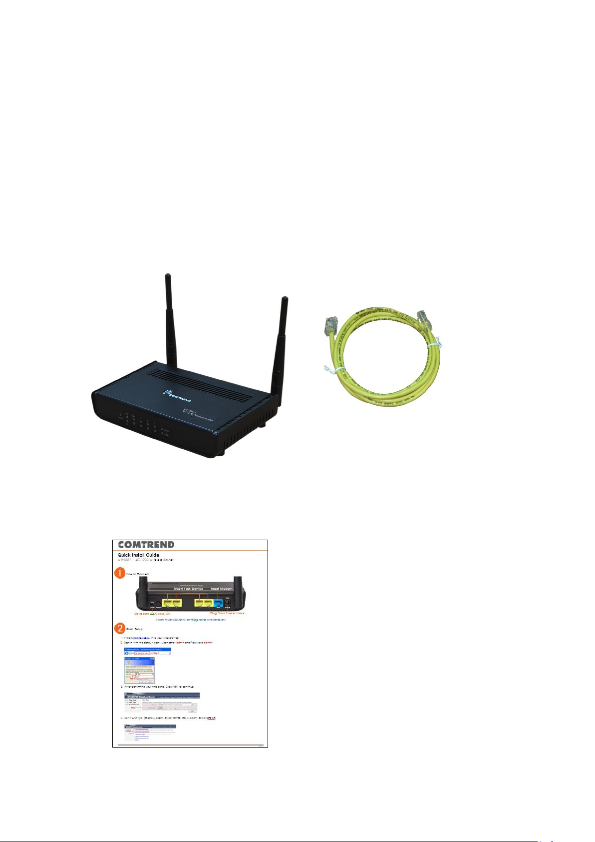
Before starting to use this router, check if there’s anything missing in the
package, and contact your place of purchase to claim for missing items:
* 1 - Broadband Router (1)
* 1 - Ethernet Cable (2)
* 1 - Printed QIG (3)
12
Page 14
1-4 Get familiar with your new Wireless-n Broadband
LED Name
Light
Status
Description
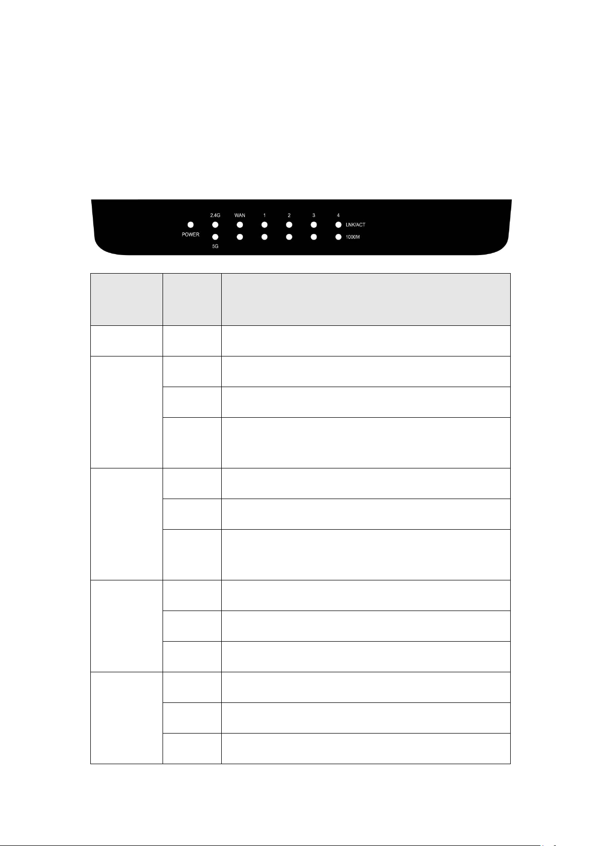
POWER
On
Router is switched on and correctly powered.
2.4G
On
2.4GHz Wireless WPS function is enabled.
Off
2.4GHz Wireless network is switched off.
Flashing
2.4GHz Wireless LAN activity (transferring or
receiving data).
5G
On
5GHz Wireless WPS function is enabled.
Off
5GHz Wireless network is switched off.
Flashing
5GHz Wireless LAN activity (transferring or
receiving data).
LAN 1-4
LNK/ACT
On
LAN port is connected.
Off
LAN port is not connected.
Flashing
LAN activity (transferring or receiving data).
WAN
LNK/ACT
On
WAN port is connected.
Off
WAN port is not connected.
Flashing
WAN activity (transferring or receiving data).
Router
Front Panel
13
Page 15

LAN 1-4
1000M
On
LAN port is linked in 1000Mbps speed.
Off
LAN port is linked in 10/100Mbps speed.
WAN
1000M
On
WAN port is linked in 1000Mbps speed.
Off
WAN port is linked in 10/100Mbps speed.
14
Page 16
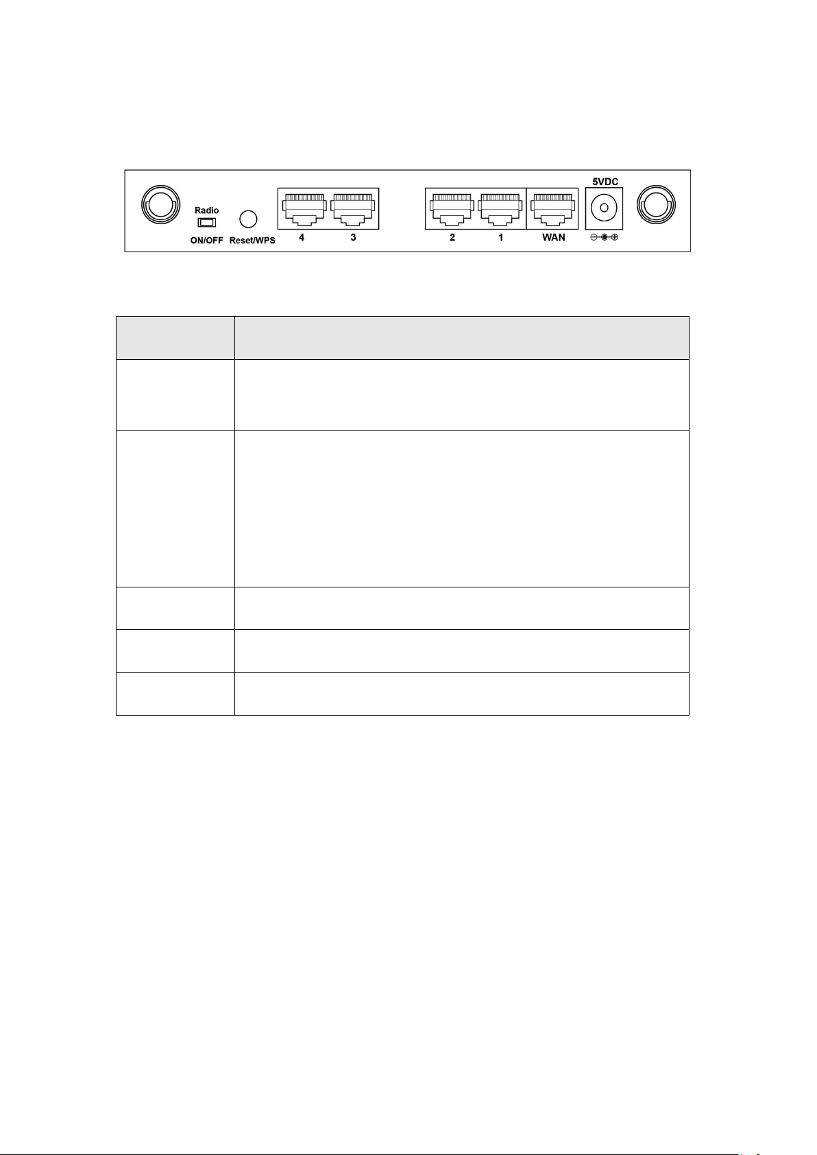
Back Panel
Item Name
Description
Radio
ON/OFF
Switch the button to activate or deactivate the wireless
function.
Reset / WPS
Reset the router to factory default settings (clear all
settings) or start WPS function. Press this button and
hold for 10 seconds to restore all settings to factory
defaults; press this button for less than 5 seconds once
to start 2.4GHz & 5GHz wireless WPS function.
1 – 4
Local Area Network (LAN) ports 1 to 4.
WAN
Wide Area Network (WAN / Internet) port.
Power
Power connector, connects to A/C power adapter.
15
Page 17
Chapter II: System and Network Setup
2-1 Installation
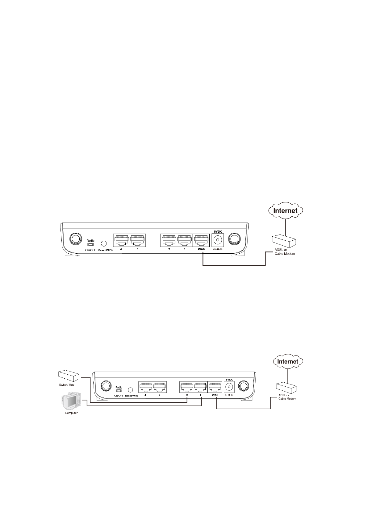
Follow the instructions below to build the network connection between
your new Wireless router and your computers, network devices:
1. Connect your xDSL / cable modem to the WAN port of the router by
Ethernet cable.
2. Connect your computers and network devices (network-enabled
consumer devices other than computers, like game consoles, or a
switch / hub) to an available LAN port of the router.
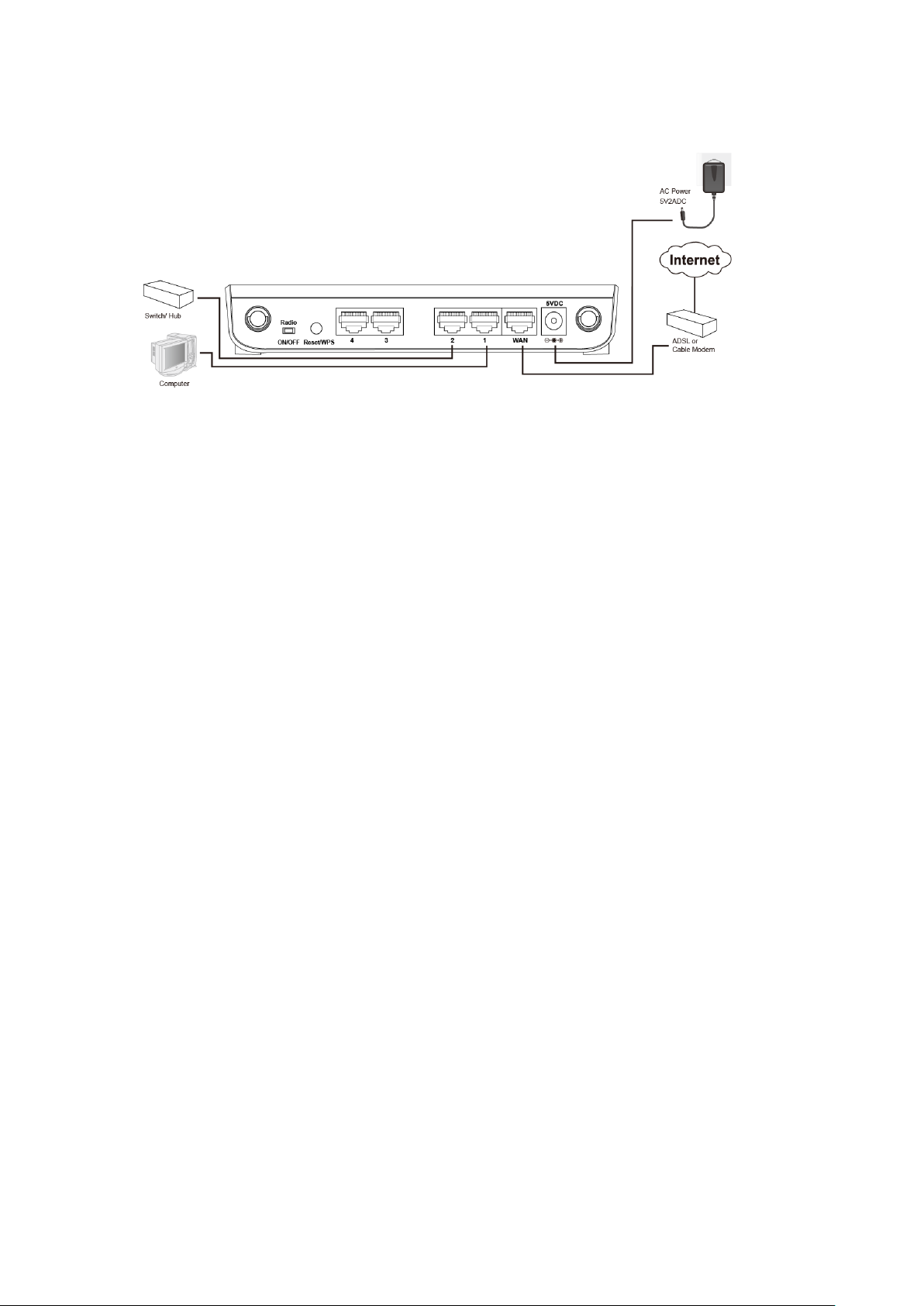
3. Insert the A/C power adapter into the wall socket, and then connect
it to the ‘Power’ socket of the router.
16
Page 18
4. Check all LEDs on the front panel. The ‘Power’ LED should be steadily
on, WAN and LAN LEDs should be on if the computer / network
devices connected to the respective port of the router is powered on
and correctly connected. If the Power LED is not on, or any LED you
expected to be on is not on, recheck the cabling, or jump to ‘4-2
Troubleshooting’ for possible reasons and solutions.
17
Page 19

2-2 Connecting to the wireless broadband router by web
browser
Before you can connect to the router and start configuration procedures,
your computer must be able to get an IP address automatically (using a
dynamic IP address). If it’s set to use a static IP address, or you’re unsure,
follow the instructions below to configure your computer to use
dynamic IP address:
18
Page 20
2-2-1 Windows 7 IP address setup:
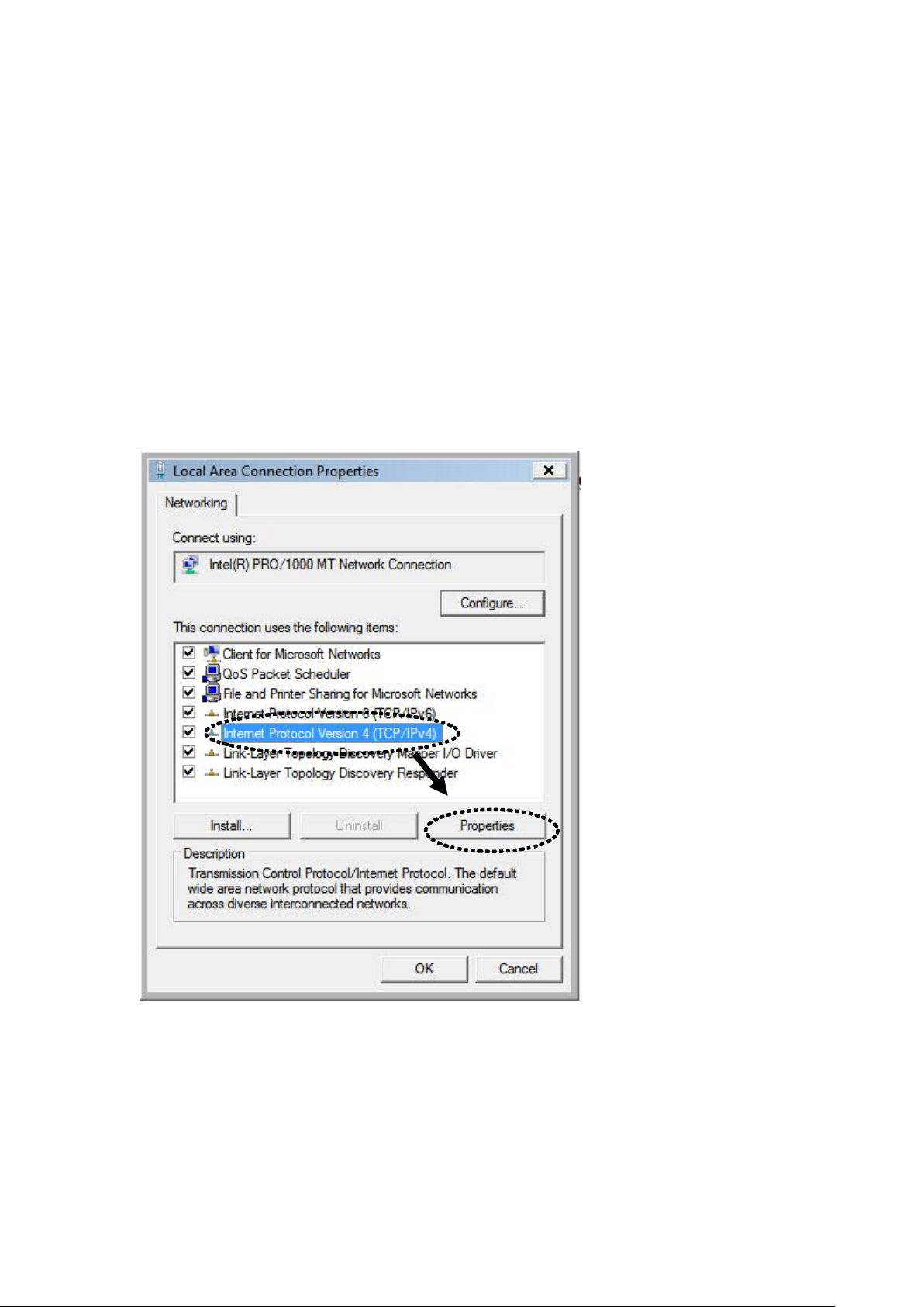
1. Click the ‘Start’ button (it should be located at the lower-left corner of
your computer screen), then click control panel. Click View Network
Status and Tasks, and then click Manage Network Connections.
Right-click Local Area Network, then select ‘Properties’. The Local Area
Connection Properties window will appear, select ‘Internet Protocol
Version 4 (TCP / IPv4), and then click the ‘Properties’ button.
19
Page 21
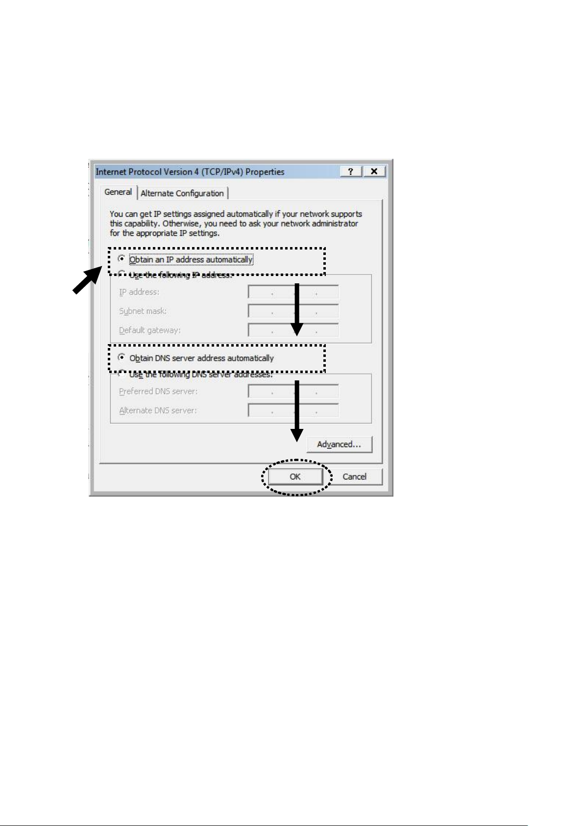
2. Select ‘Obtain an IP address automatically’ and ‘Obtain DNS server
address automatically’, then click the ‘OK’ button.
20
Page 22
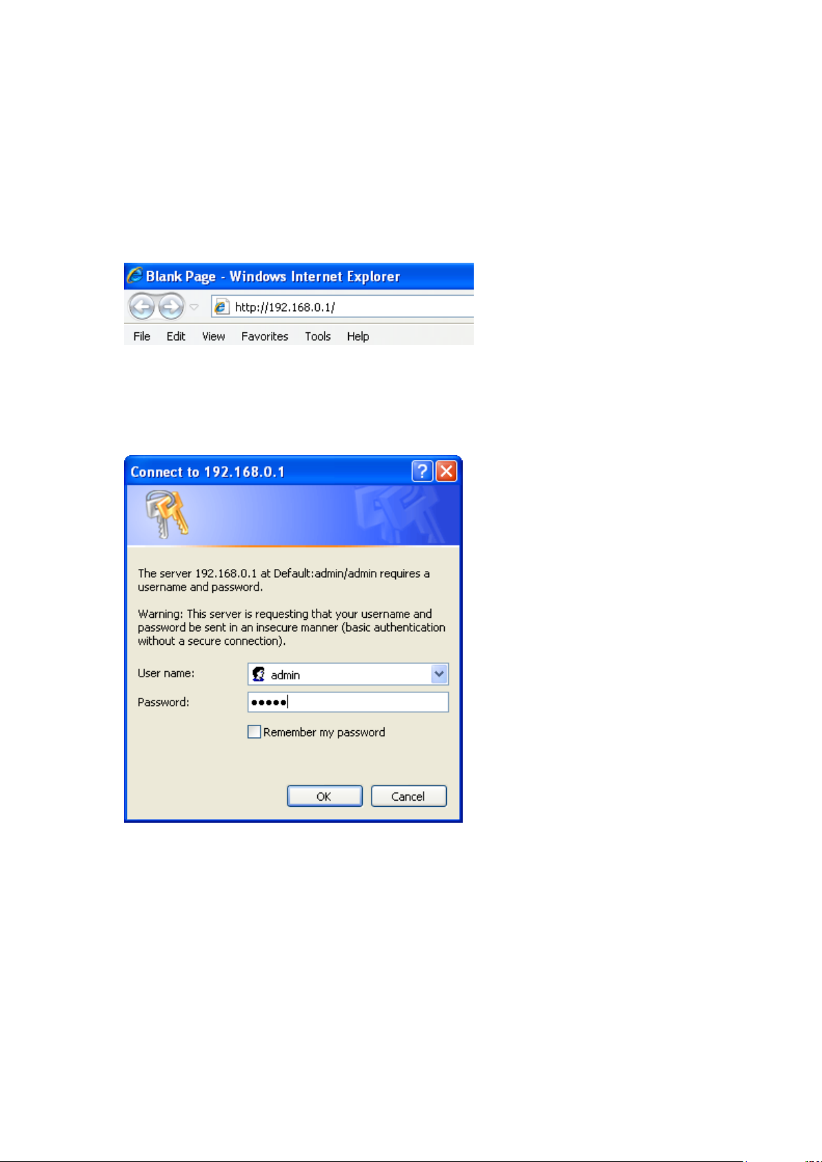
Connect to the router’s management interface by web browser.
Start your web browser, and input the default IP address of the router
in the address bar, type http://192.168.0.1
A dialog box will appear, such as the one below.
Input the user name and password in their respective fields, the default
user name is ‘admin’, and the default password is ‘admin’, then press
the ‘OK’ button, and you can see the Quick Setup interface of this router:
21
Page 23
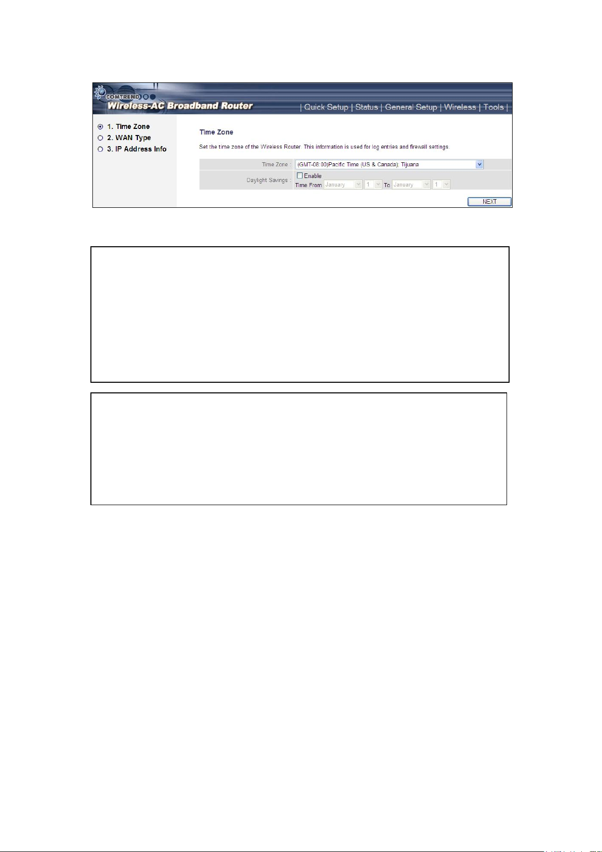
NOTE: If you can’t see the web management interface, and you’re being
prompted to input the user name and password again, it means you didn’t
input the username and password correctly. Please retype the user name
and password again. If you’re certain that the user name and password you
type are correct, please go to ‘4-2 Troubleshooting’ to perform a factory
reset, to set the password back to its default value.
TIP: This page shows the five major setting categories: Quick Setup, Status,
General Setup, Wireless and Tools. You can find the shortcut which leads to
these setting categories at the upper-right corner of every page, and you
can jump to another category directly by clicking the link, you don’t have to
go back to the first page.
22
Page 24
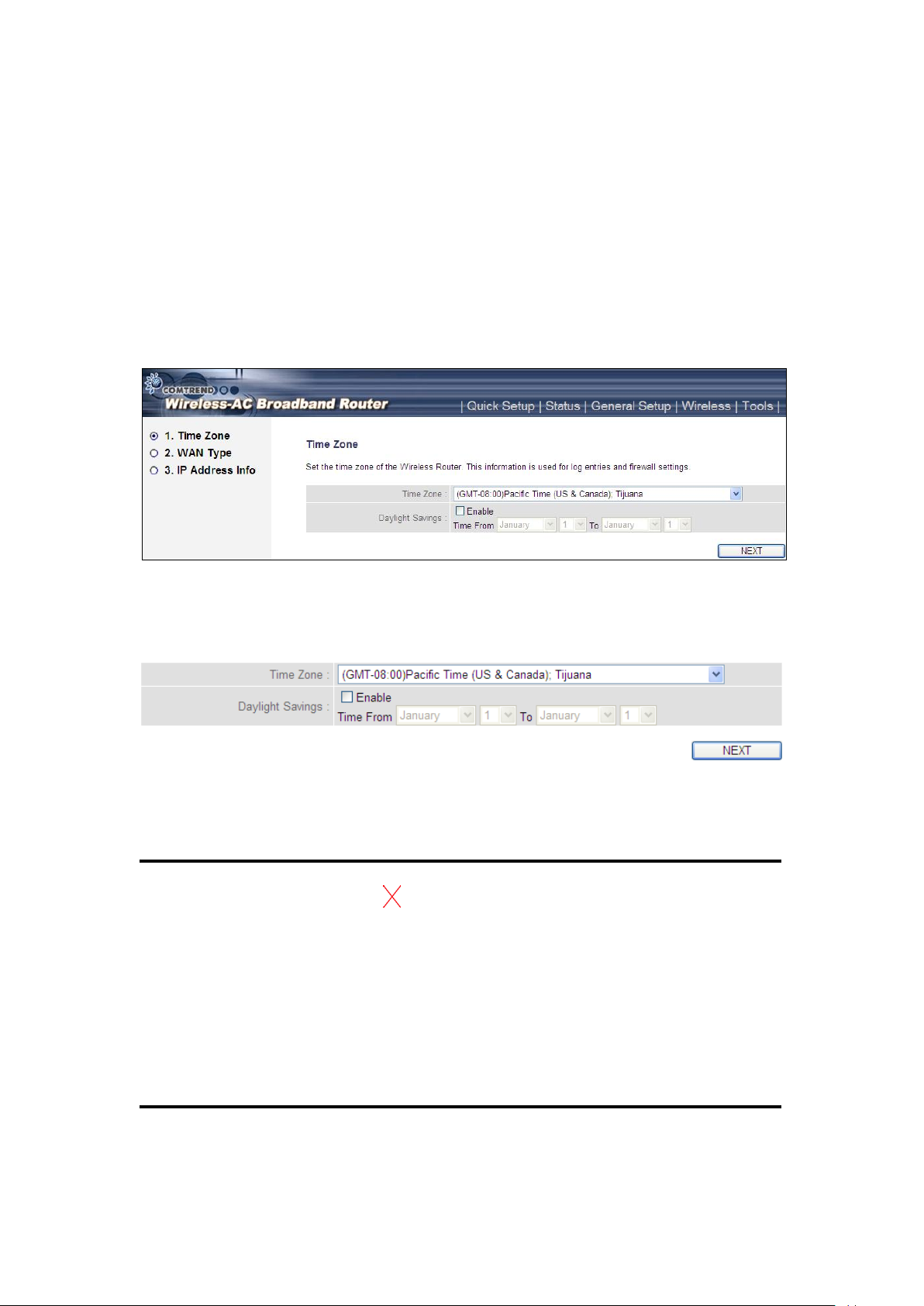
2-3 Using ‘Quick Setup’
1
2
3
This router provides a ‘Quick Setup’ procedure, which will help you to
complete all the required settings you need to access the Internet in a very
short time. Follow these instructions to complete the ‘Quick Setup’:
After successfully logging in for the first time, you will reach the ‘Quick
Setup’ screen.
1. Set Time Zone
Here are descriptions of every setup item:
Set Time Press button, a drop-down list
Zone (1): will be shown, and you can choose the time zone of
the location in which you live.
Daylight If the country you live in uses daylight savings,
Savings (2): Check the ‘Enable Function’ box, and choose the
duration of daylight savings.
After you complete all settings, click the ‘Next’ (3) button.
23
Page 25
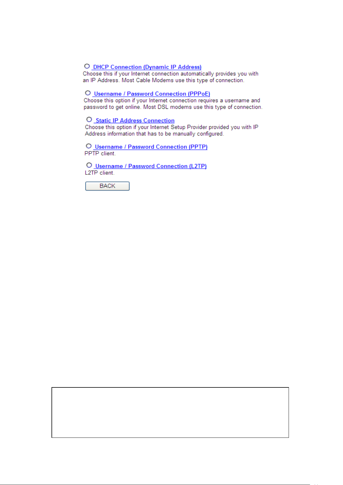
2. WAN Type
NOTE: Some service providers use ‘DHCP’ (Dynamic Host Configuration
Protocol) to assign IP address to you. In this case, you can choose ‘DHCP
Connection (Dynamic IP Address)’ as the Internet connection type, even
though you’re using another connection type, like xDSL.
Choose the WAN (Internet connection) type you’re using on this page.
There are five options for the type of Internet connection:
DHCP Connection (Cable Modem) - go to section 2-3-1
Username / Password Connection (PPPoE) - go to section 2-3-2
Static IP Address Connection (Fixed-IP) - go to section 2-3-3
Username / Password Connection (PPTP) - go to section 2-3-4
Username / Password Connection (L2TP) - go to section 2-3-5
If you’re not sure, contact your Internet service provider. A wrong
Internet connection type will cause a connection problem, and you will
not be able to connect to the Internet.
If you want to go back to the previous step, press the ‘Back’ button on
the bottom of this page.
24
Page 26
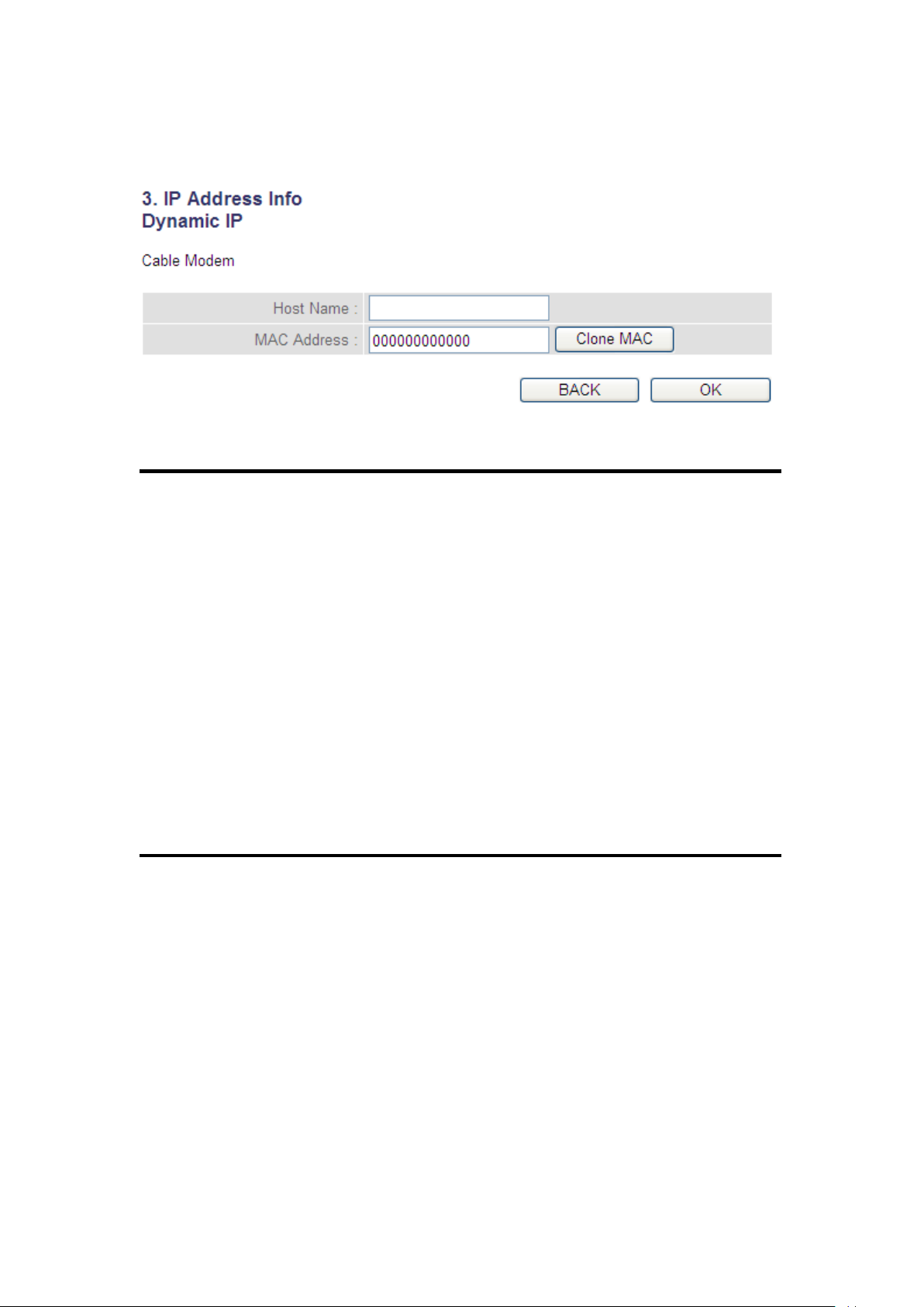
2-3-1 Setup procedure for ‘Dynamic IP’ (Cable Modem)
1
2
3
Here are descriptions of every setup item:
Host Name (1): Input the host name of your computer, this is
optional, and only required if your service provider
asks you to do so.
MAC address (2): Input the MAC address of your computer, if your
service provider only permits computers with a
certain MAC address to access the Internet. If
you’re using the computer which was used to
connect to the Internet via cable modem, you can
simply press the ‘Clone Mac address’ button to fill
the MAC address field with the MAC address of
your computer.
After you complete all settings, click the ‘OK’ (3) button; if you want to
go back to previous menu, click the ‘Back’ button.
25
Page 27
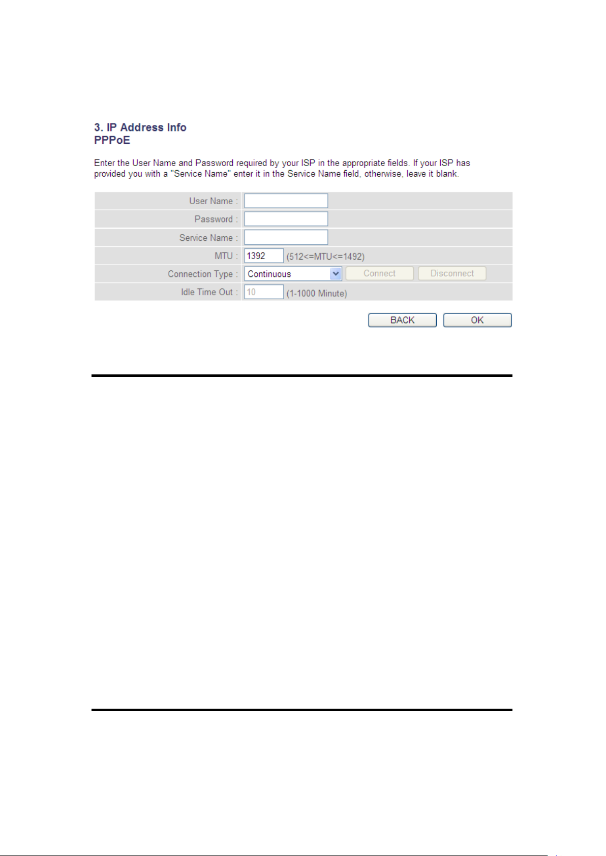
2-3-2 Setup procedure for PPPoE
1
2 4 3
5
6
7
Here are descriptions of every setup item:
User Name (1): Input the user name assigned by your Internet
service provider.
Password (2): Input the password assigned by your Internet
service provider.
Service Name (3): Give a name to this Internet service. This is
optional.
MTU (4): Input the MTU value of your network connection. If
you don’t know, you can use the default value.
Connection Select the Internet connection type
Type (5): you wish to use (detailed explanation listed below).
Idle Time Out (6): Input the idle time out, (detailed explanation listed
below).
When you complete all settings, click the ‘OK’ (7) button; if you want to
go back to the previous menu, click the ‘Back’ button.
26
Page 28

MTU - Please use the default value if you don’t know what it is, or ask your
service provider for a proper value.
Connection Type - There are 3 options:
‘Continuous’ - keep Internet connection alive, do not disconnect,
Connect on Demand - only connects to the Internet when there’s a
connection attempt,
‘Manual’ - only connects to the Internet when the ‘Connect’ button on this
page is pressed, and disconnects when the ‘Disconnect button is pressed.
Idle Time Out: Specify the time to shutdown the Internet connection after no
Internet activity is detected by minute. This option is only available when
connection type is ‘Connect on Demand’.
27
Page 29
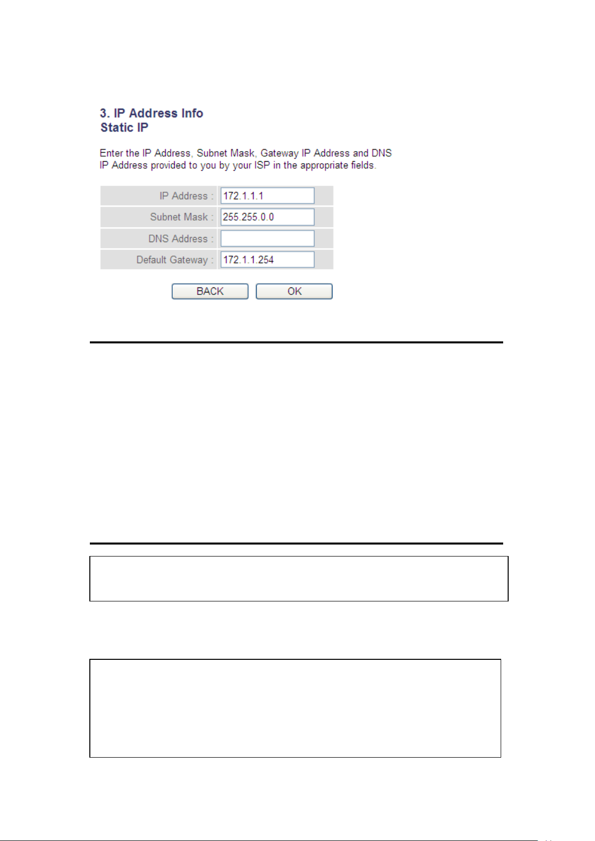
2-3-3 Setup procedure for Static IP
1 2 3
4
5
NOTE: You can choose this Internet connection method if your service
provider assigns a fixed IP address (also known as a static address) to you,
and doesn’t use DHCP or PPPoE protocol. Please contact your service
provider for further information.
You must use the addresses provided by your Internet service provider,
incorrect setting values will cause connection problems.
Here are descriptions of every setup item:
IP Address (1): Input the IP address assigned by your service
provider.
Subnet Mask (2): Input the subnet mask assigned by your service
provider.
DNS address (3): Input the IP address of the DNS server provided by
your service provider.
Default Gateway(4): Input the IP address of the DNS server
Gateway Address provided by your service provider.
When you complete all settings, press the ‘OK’ (5) button; if you want to
go back to the previous menu, click the ‘Back’ button.
28
Page 30
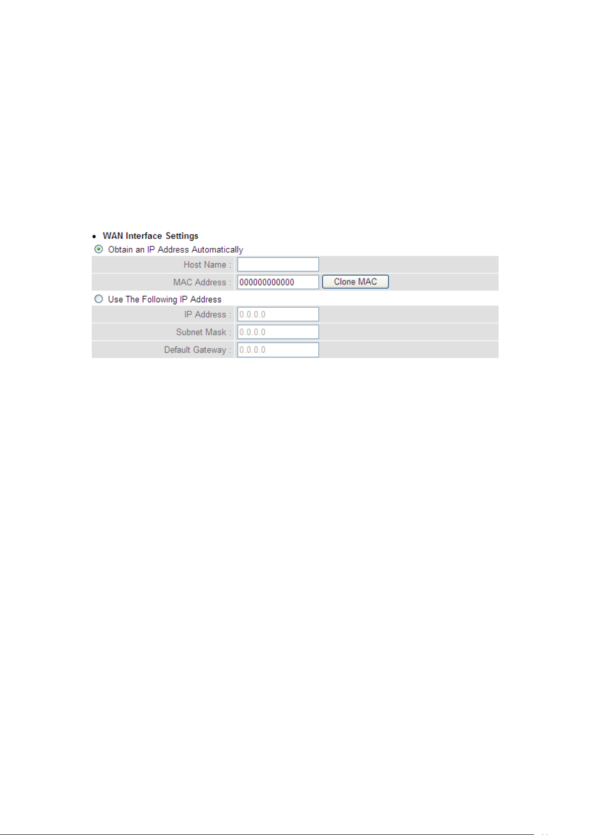
2-3-4 Setup procedure for PPTP
PPTP xDSL requires two kinds of settings: WAN interface setting (setup
IP address) and PPTP setting (PPTP user name and password). Here we
start from the WAN interface setting:
Select how you obtain and IP address from your service provider. You
can choose ‘Obtain an IP address automatically’ (equal to DHCP, refer to
‘Cable Modem’ section above), or ‘Use the following IP address’ (i.e.
static IP address).
WAN interface settings must be correctly set, or the Internet connection
will fail even though the PPTP settings are correct. Contact your Internet
service provider if you don’t know how to fill in these fields.
Now go to the PPTP settings section:
29
Page 31

1
2
3 4 5 6 7 9 8
Here are descriptions of every setup item:
User Name (1): Input the user ID (user name) assigned by your
Internet service provider.
Password (2): Input the password assigned by your Internet
service provider.
PPTP Input the IP address of PPTP gateway
Gateway (3): assigned by your Internet service provider.
Connection Input the connection ID. This is
ID (4): optional and you can leave it blank.
MTU (5): Input the MTU value of your network connection. If
you don’t know, you can use the default value.
30
Page 32

BEZEQ-ISRAEL (6): Setting item ‘BEZEQ-ISRAEL’ is only required to
Check if you’re using the service provided by the
BEZEQ network in Israel.
Connection Select the type of Internet
type (7): connection you wish to use, refer to the previous
section for detailed descriptions.
Idle Time Input the idle time out of the Internet
Out (8): connection you wish to use, and refer to the
previous section for detailed descriptions.
When you complete all settings, click the ‘OK (9) button; if you want to
go back to previous menu, click the ‘Back’ button.
31
Page 33
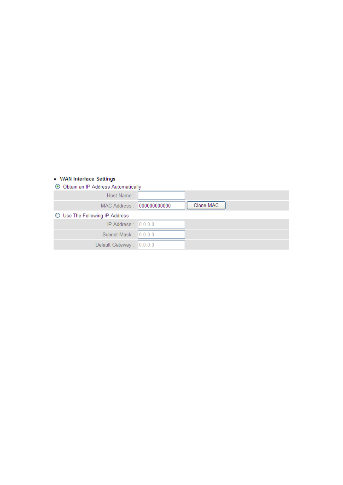
2-3-5 Setup procedure for L2TP
L2TP is another popular connection method for xDSL and other Internet
connection types, and all required setting items are the same as a PPTP
connection.
Like PPTP, there are two kinds of required settings, we’ll start from
‘WAN Interface Settings’:
Select how you obtain IP address from your service provider. You can
choose ‘Obtain an IP address automatically’ (equal to DHCP, refer to the
‘Cable Modem’ section above), or ‘Use the following IP address’ (equal
to static IP address, refer to the ‘PPPoE xDSL’ section above).
WAN interface settings must be correctly set, or the Internet connection
will fail even thought the PPTP settings are correct. Contact your
Internet service provider if you don’t know how to fill in these fields.
Now go to L2TP settings section:
32
Page 34
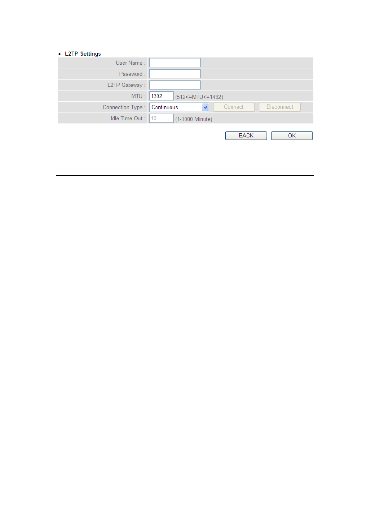
Here are descriptions of every setup item:
1
2
4 3 5
7
6
User Name (1): Input the user ID (user name) assigned by
your Internet service provider.
Password (2): Input the password assigned by your Internet
service provider.
L2TP Gateway (3): Input the IP address of L2TP gateway assigned by
your Internet service provider.
MTU (4): Input the MTU value of your network connection. If
you don’t know, you can use the default value.
Connection Select the type of Internet
type (5): connection you wish to use, refer to last section for
detailed descriptions.
33
Page 35
Idle Time Input the idle time out of Internet
Out (6): connection you wish to use, and refer to last section
for detailed descriptions.
When you complete all settings, click the ‘OK (7) button; if you want to
go back to previous menu, click the ‘Back’ button.
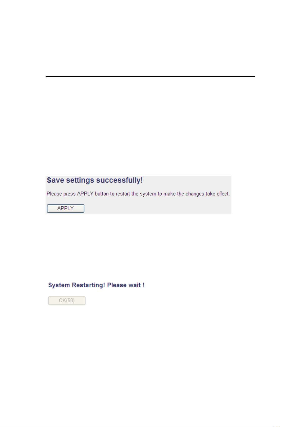
When all settings are completed, you’ll see the following message
displayed on your web browser:
Click the ‘Apply’ button to prepare to restart the router, and you’ll see
this message:
After the countdown, click the ‘OK!’ button. You’ll be brought back to
the router management interface again, and the router is ready with
new settings.
34
Page 36
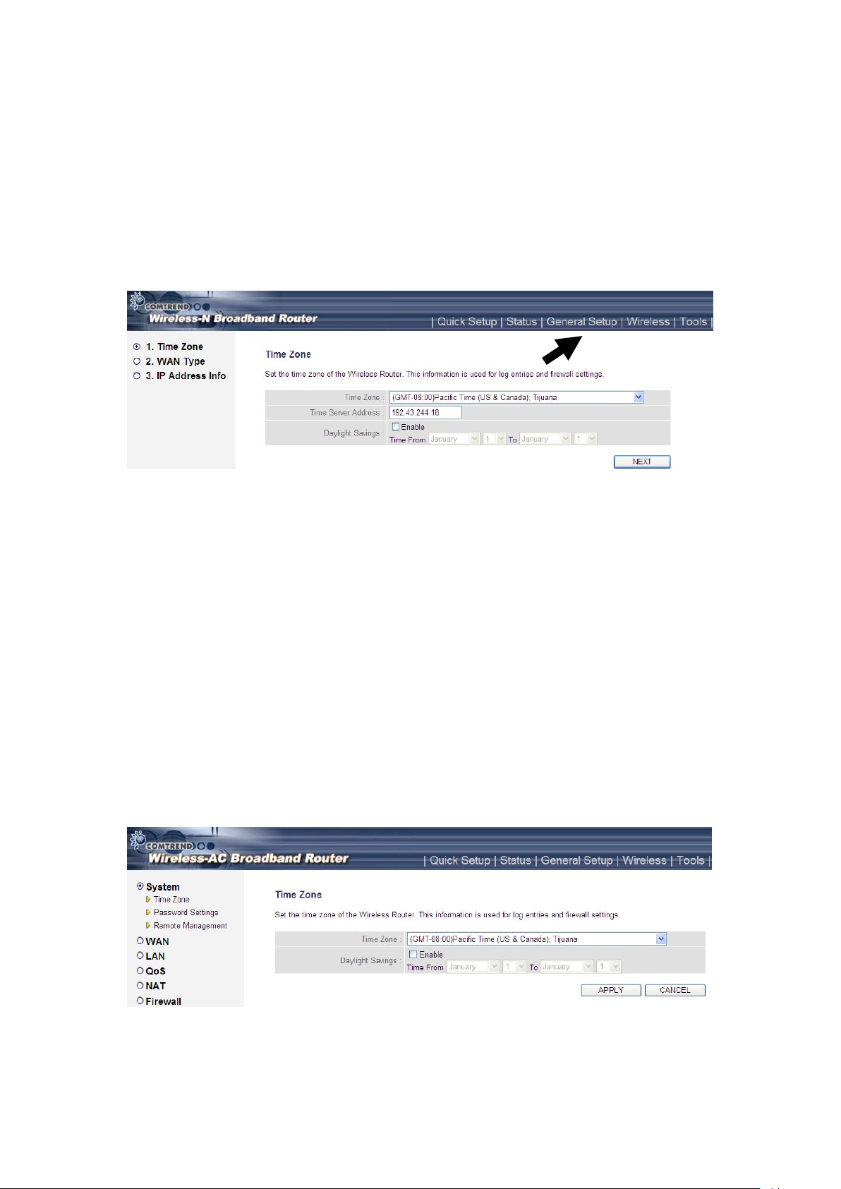
2-4 Basic Setup
In this chapter, you’ll learn how to change the time zone, password, and
remote management settings. Start your web browser and log into the
router web management interface, and then click the ‘General Setup’
link at the upper-right side of the web management interface.
2-4-1 Time zone and time auto-synchronization
Follow the instructions below to set time zone and time
auto-synchronization parameters:
Click the ‘General Setup’ menu at the upper-right side of the web
management interface, and then select System on the left menu bar
followed by Time Zone.
35
Page 37
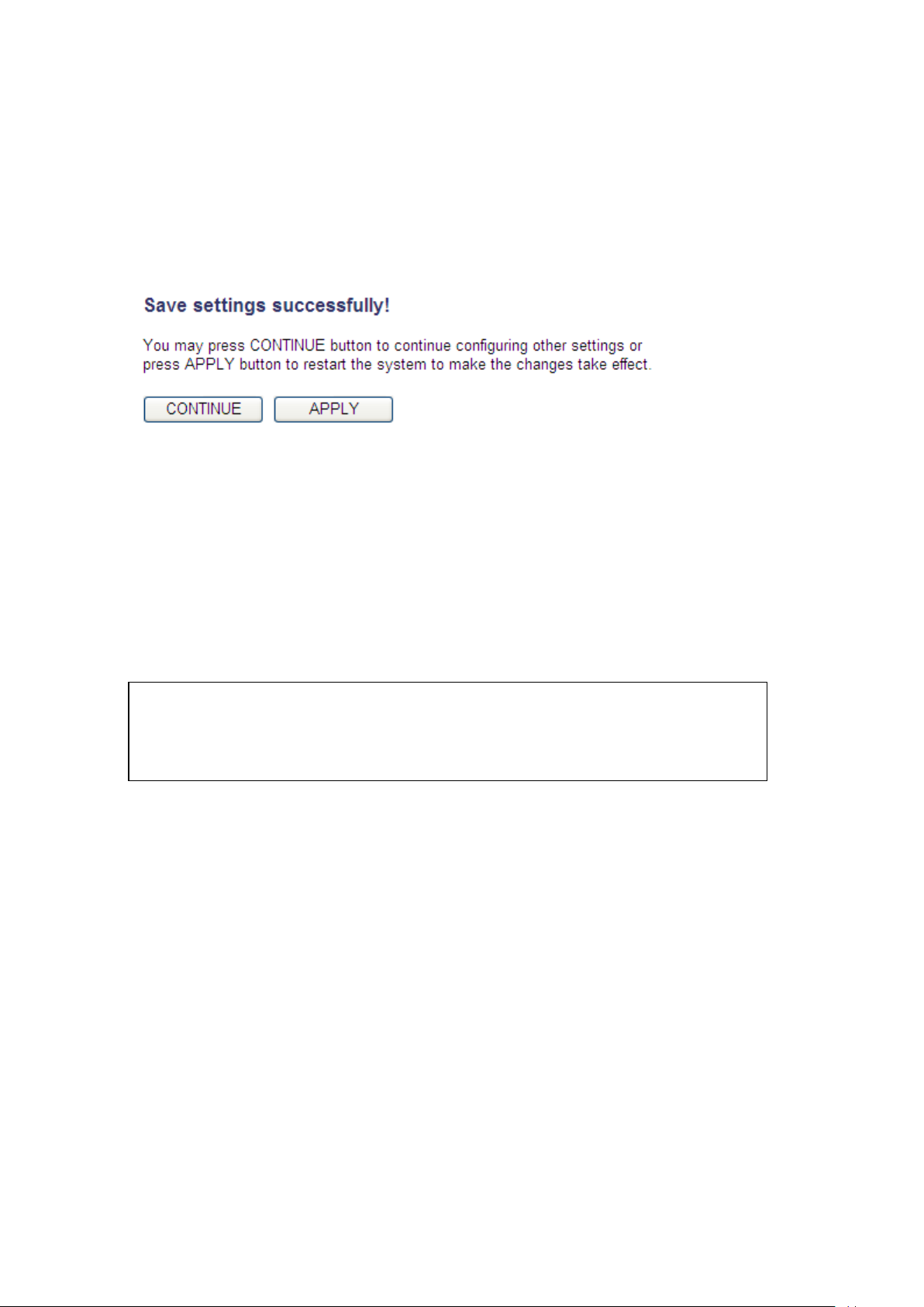
Select the time zone from the ‘Set time zone’ drop-down list, and input
NOTE: You can refer to the instructions given in the last chapter: ‘Using
Quick Setup’, for detailed descriptions on time zone settings.
the IP address or host name of the time server. If you want to enable the
daylight savings setting, check the ‘Enable Function’ box, and set the
duration of daylight setting. When you finish, click the ‘Apply’ button.
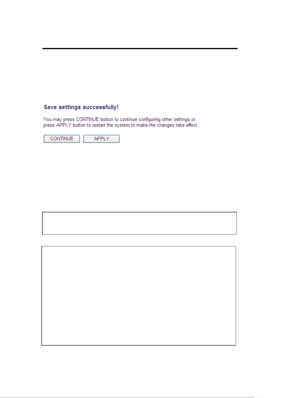
You’ll see the following message displayed on the web browser:
Press the ‘Continue’ button to save the settings and go back to the web
management interface; press the ‘Apply’ button to save the settings
made and restart the router so the settings will take effect after it
reboots.
36
Page 38
2-4-2 Change management password
2
3
1
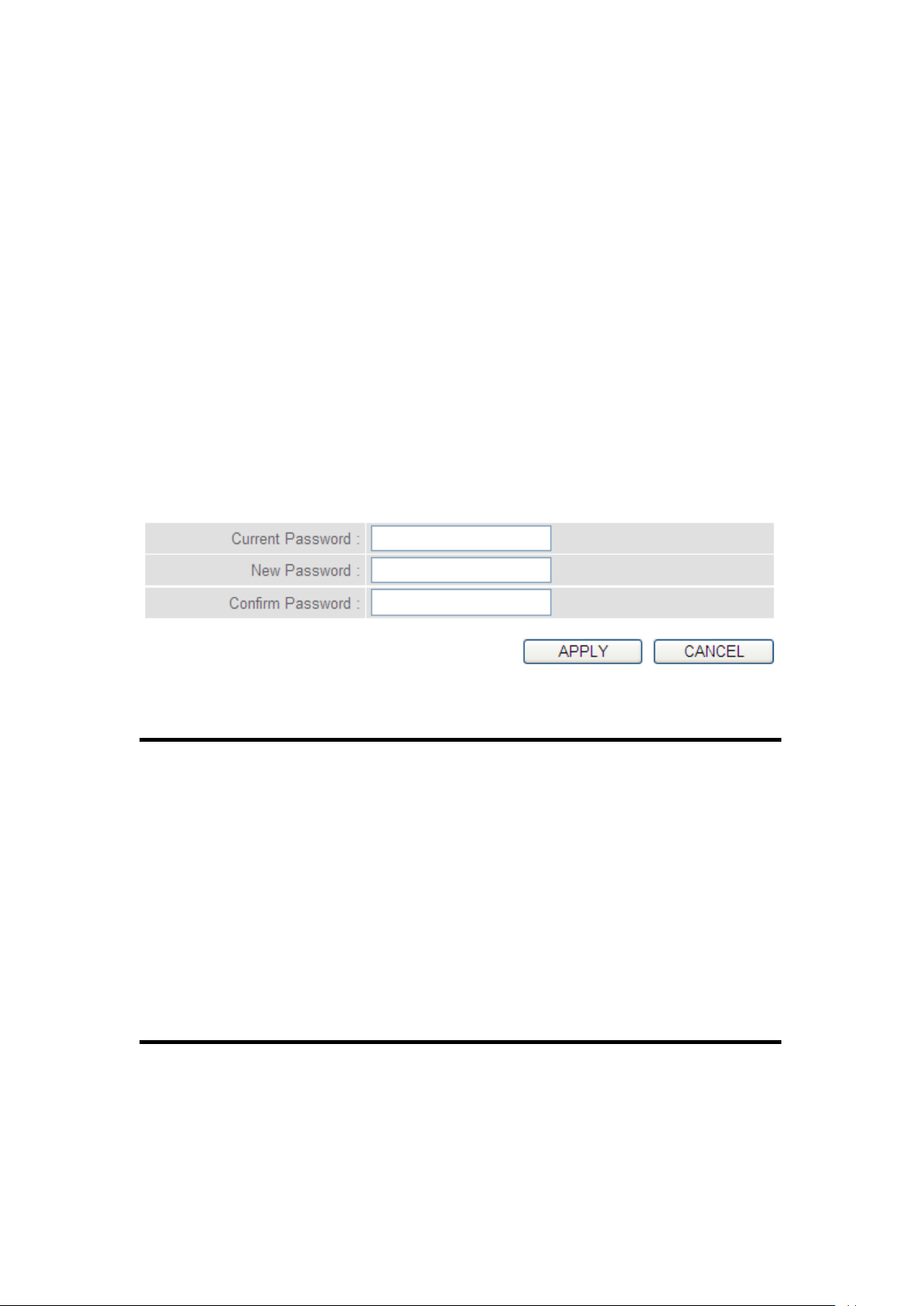
The default password of this router is admin, and it’s displayed on the
login prompt when accessed from the web browser.
To change the password, follow the instructions below:
Click the ‘System’ menu on the left of the web management interface,
then click ‘Password Settings’, and the following will be displayed on
your web browser:
Here are descriptions of every setup item:
Current Input current password.
Password (1):
New Password (2): Input new password.
Confirm Input new password again.
Password (3):
When you finish, click the ‘Apply’ button. If you want to keep the original
password unchanged, click the ‘Cancel’ button.
37
Page 39
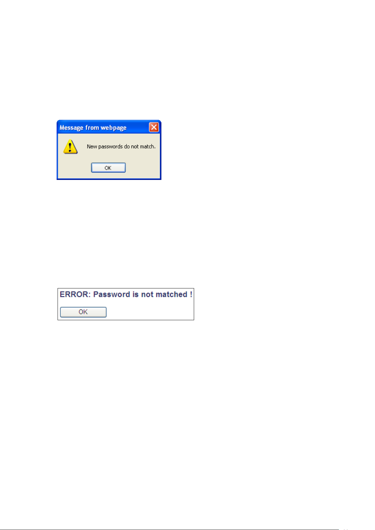
If the password you typed in ‘New Password’ (2) and ‘Confirmed
Password’ (3) field are not the same, you’ll see the following message:
Retype the new password again when you see the above message.
If you see the following message:
It means the content in ‘Current Password’ field is wrong, click the ‘OK’
button to go back to previous menu, and try to input current password
again.
If the current and new passwords are correctly inputted, after you click
the ‘Apply’ button, you’ll be prompted to input your new password:
38
Page 40
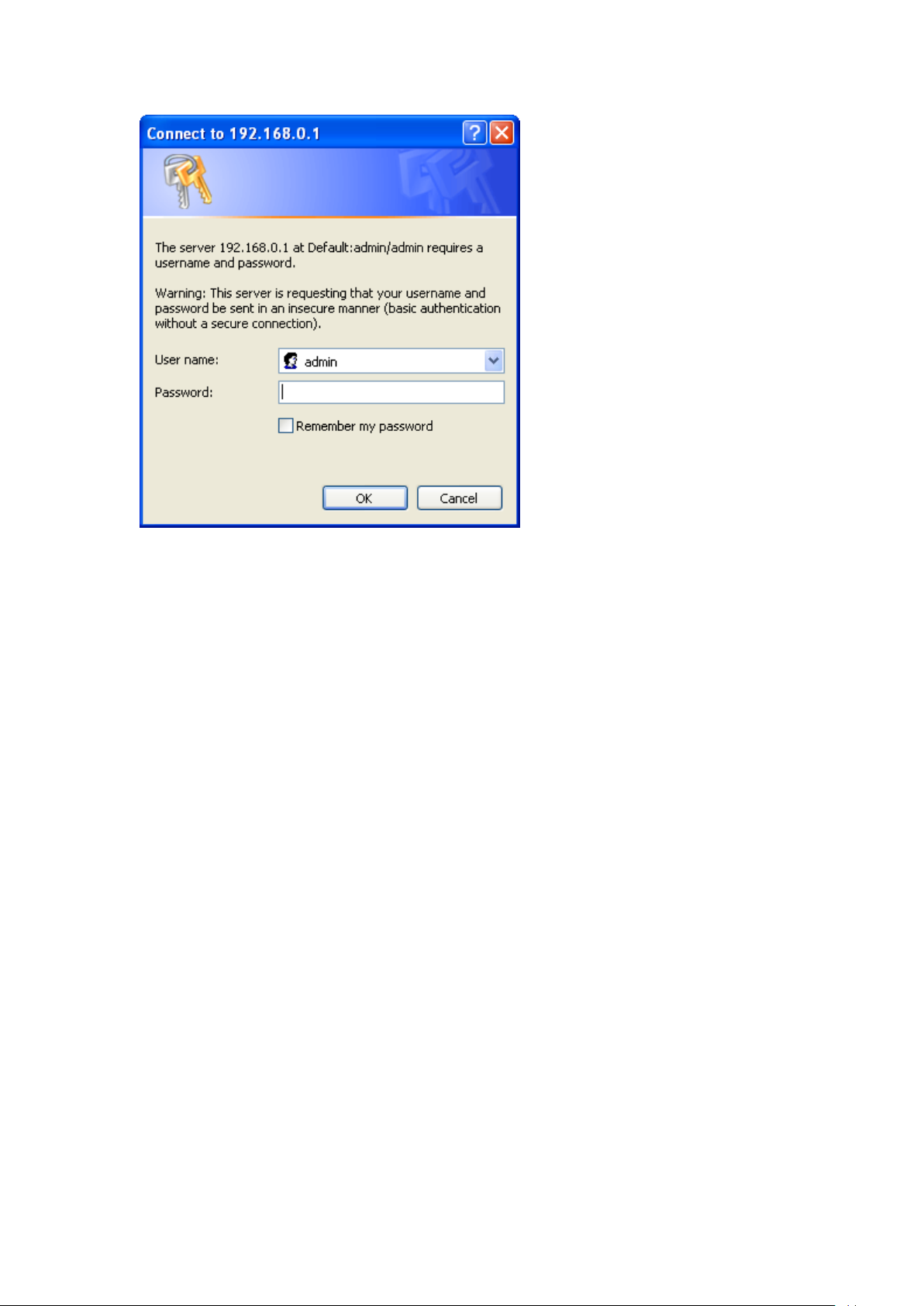
Use the new password to enter web the management interface again.
39
Page 41
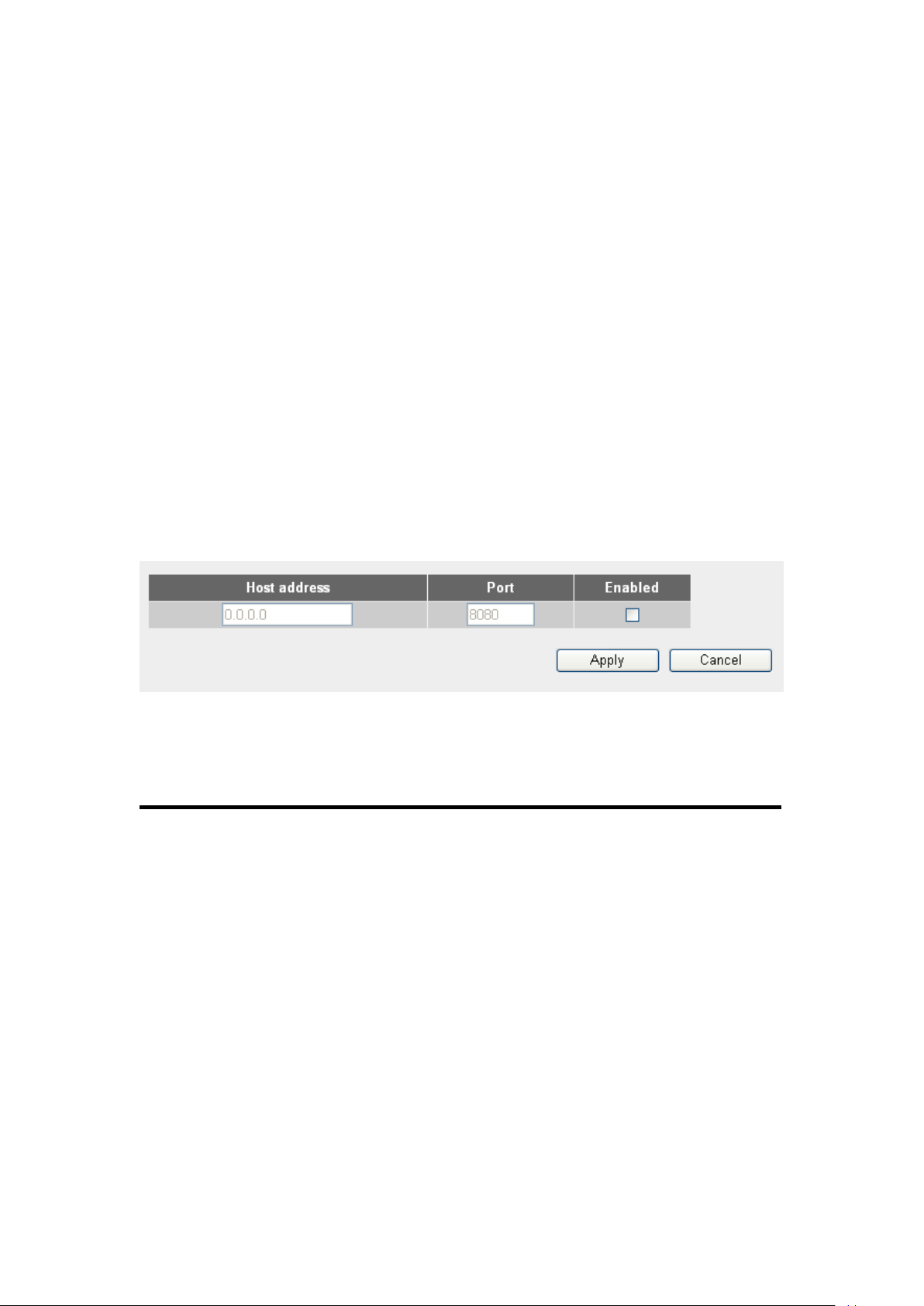
2-4-3 Remote Management
2
3
4
This router does not allow remote management access from the Internet
by default. However, you can still manage this router from a specific IP
address by enabling the ‘Remote Management’ Function.
To do so, follow the instructions below:
Click the ‘System’ menu on the left of the web management interface,
then click ‘Remote Management’, and the following will be displayed on
your web browser:
Here are descriptions of every setup item:
Host Address (1): Input the IP address of the remote host you wish to
initiate management access with.
Port (2): You can define the port number this router should
expect an incoming request from. If you’re
providing a web service (default port number is 80),
you should try to use another port number. You can
use the default port setting ‘8080’, or something
like ‘32245’ or ‘1429’. (Any integer between 1 and
65534)
40
Page 42
Enabled (3): Select the field to enable the configuration.
NOTE: When you want to manage this router from another computer on the
Internet, you have to input the IP address and port number of this router.
NOTE: The default port number the web browser will use is ‘80’. If the ‘Port’
setting in this page is not ‘80’, you have to assign the port number in the
address bar of the web browser manually. For example, if the IP address of
this router is 1.2.3.4, and the port number you set is 8888, you have to input
following address in the address bar of web browser:
http://1.2.3.4:8888
When you complete all settings, click the ‘Apply’ button, and you’ll see
the following displayed on the web browser:
Click the ‘Continue’ button to save the settings made and go back to the
web management interface; press ‘Apply’ to save the settings made and
restart the router so the settings will take effect after it reboots.
41
Page 43
2
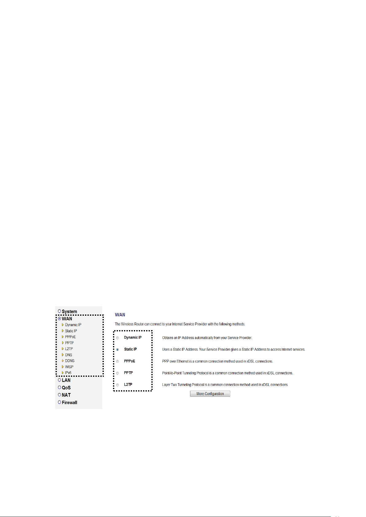
2-5 Setup Internet Connection (WAN Setup)
The Internet connection setup can be completed by using the ‘Quick
Setup’ procedure as described in section 2-3. However, you can setup
WAN connections by using the WAN configuration menu. You can also
set advanced functions like DDNS (Dynamic DNS) here.
For WAN setup, follow these instructions:
Click the ‘WAN’ menu on the left of the web management interface.
Select an Internet connection method depending on the type of
connection you’re using. You can either click the connection method on
the left (1) or right (2). If you select the connection method on the right,
click the ‘More Configuration’ button after a method is selected.
Dynamic IP - go to section 2-5-1
PPPoE - go to section 2-5-2
42
Page 44

Static IP - go to section 2-5-3
PPTP - go to section 2-5-4
L2TP - go to section 2-5-5
DNS - go to section 2-5-6
DDNS - go to section 2-5-7
WISP - go to section 2-5-8
IPv6 - go to section 2-5-9
43
Page 45
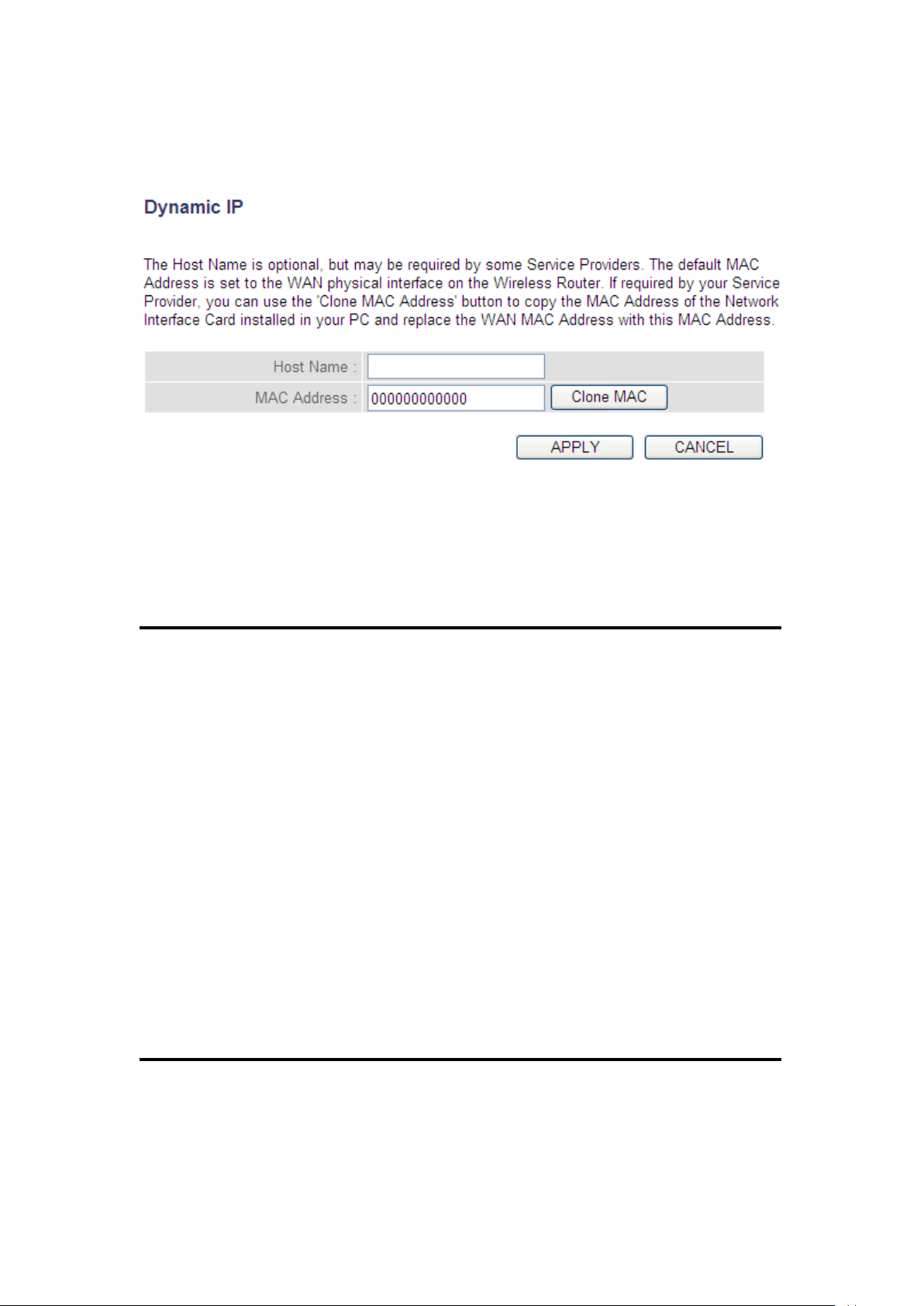
2-5-1 Setup procedure for ‘Dynamic IP’:
1 2 3
Here are descriptions of every setup item:
Host Name (1): Input the host name of your computer, this is
optional, and only required if your service provider
asks you to do so.
MAC Address (2): Input the MAC address of your computer, if your
service provider only permits computers with
certain MAC address to access the Internet. If
you’re using a computer which is used to connect to
the Internet via cable modem, you can simply press
the ‘Clone Mac address’ button to fill the MAC
address field with the MAC address of your
computer.
After you complete all settings, click the ‘Apply’ (3) button; if you want
to remove the values you inputted, click the ‘Cancel’ button.
44
Page 46
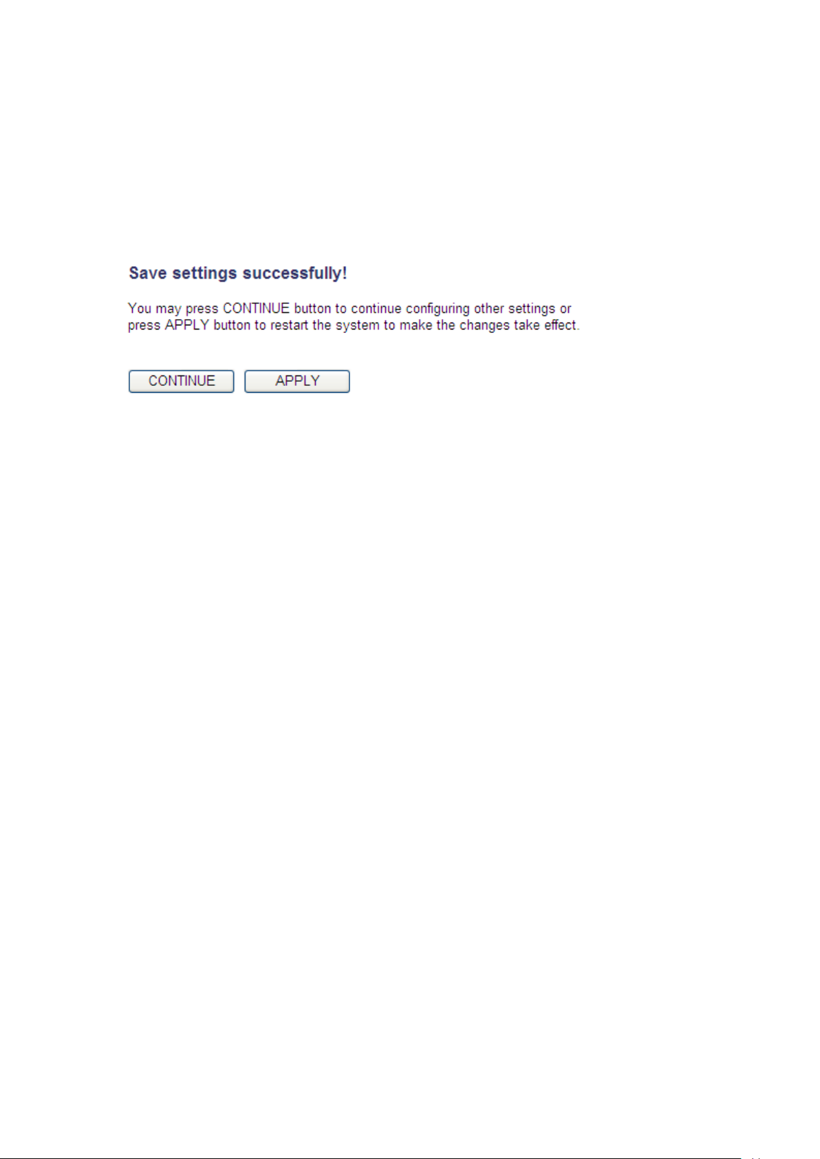
After you click the ‘Apply’ button, the following will be displayed on your
web browser:
Click the ‘Continue’ button to go back to the previous setup menu; to
continue on router setup, or click the ‘Apply’ button to reboot the router
so the settings will take effect (wait for about 60 seconds while the
router is rebooting).
45
Page 47
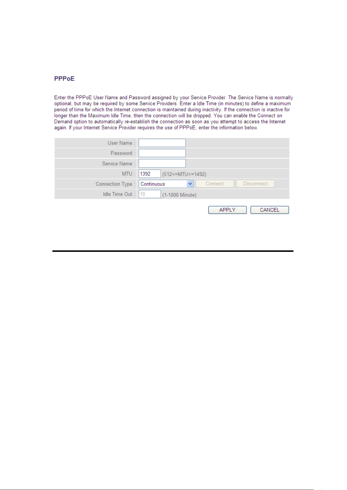
2-5-2 Setup procedure for ‘PPPoE’:
1
2
4
3
5
6
7
Here are descriptions of every setup item:
User Name (1): Input the user name assigned by your Internet
service provider.
Password (2): Input the password assigned by your Internet
service provider.
Service Name (3): Give a name to this Internet service. This is
optional.
MTU (4): Input the MTU value of your network connection. If
you don’t know, you can use the default value.
Connection Select the type of Internet connection you wish
Type (5): to use.
46
Page 48

Continuous – The connection will be always kept on. If
the connection is interrupted, the router will re-connect
automatically.
Connect On-Demand – Only connect when you want to
surf the Internet. “Idle Time Out” is set to stop the
connection when the network traffic is not sending or
receiving after an idle time.
Manual – After you have selected this option, you will
see the “Connect” button and “Disconnect” button, click
the “Connect” button and the router will connect to the
ISP. If you want to stop the connection, click the
“Disconnect” button.
Idle Time Out (6): If you have selected the connection type to
“Connect-On-Demand”, input the idle time out.
After you complete all settings, click the ‘Apply’ (7) button and the
following will be displayed on your web browser:
47
Page 49

Click the ‘Continue’ button to go back to the previous setup menu; to
continue on other setup procedures, or click the ‘Apply’ button to
reboot the router so the settings will take effect (wait for about 60
seconds while the router is rebooting).
If you want to reset all the settings in this page back to previously-saved
values, click the ‘Cancel’ button.
48
Page 50
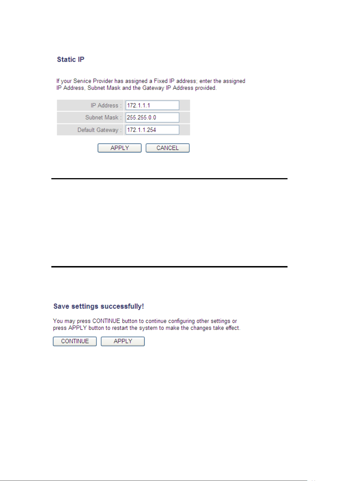
2-5-3 Setup procedure for ‘Static IP’:
1
2
3
4
Here are descriptions of every setup item:
IP address(1): Input the IP address assigned by your service
provider.
Subnet Mask (2): Input subnet mask assigned by your service
provider.
Service Provider Input the IP address of the DNS
Gateway Address (3): server provided by your service provider.
After you complete all settings, click the ‘Apply’ (4) button and the
following will be displayed on your web browser:
Click the ‘Continue’ button to go back to the previous setup menu; to
continue on other setup procedures, or click the ‘Apply’ button to
reboot the router so the settings will take effect (wait for about 60
seconds while the router is rebooting).
If you want to reset all the settings in this page back to previously-saved
values, click the ‘Cancel’ button.
49
Page 51
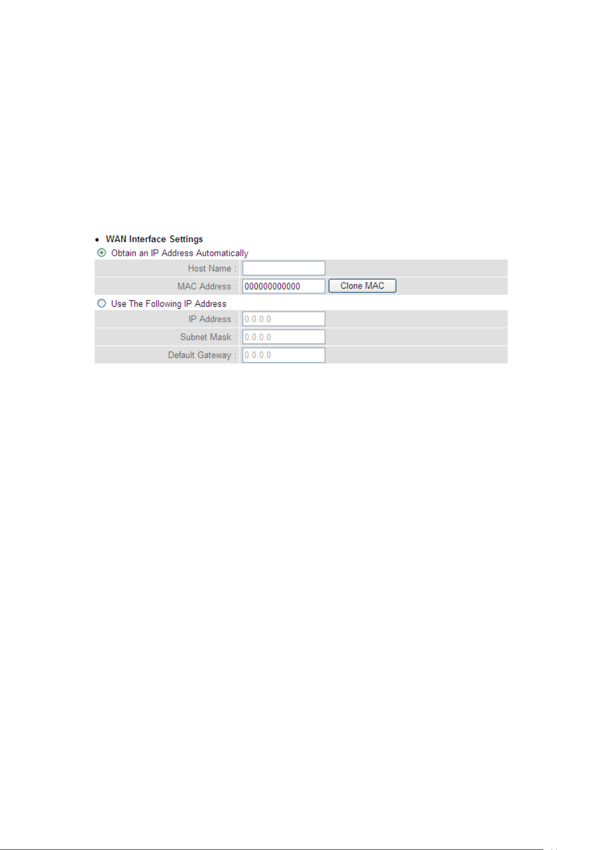
2-5-4 Setup procedure for ‘PPTP’:
PPTP requires two kinds of settings: the WAN interface setting (setup IP
address) and the PPTP setting (PPTP user name and password). Here we
start from the WAN interface setting:
Select how you obtain an IP address from your service provider. You can
choose ‘Obtain an IP address automatically’ (equal to DHCP, refer to
‘Cable Modem’ section above), or ‘Use the following IP address’ (i.e.
static IP address)
The WAN interface settings must be correctly set, or the Internet
connection will fail even though the PPTP settings are correct. Contact
your Internet service provider if you don’t know what you should put in
these fields.
Now go to the PPTP settings section:
50
Page 52
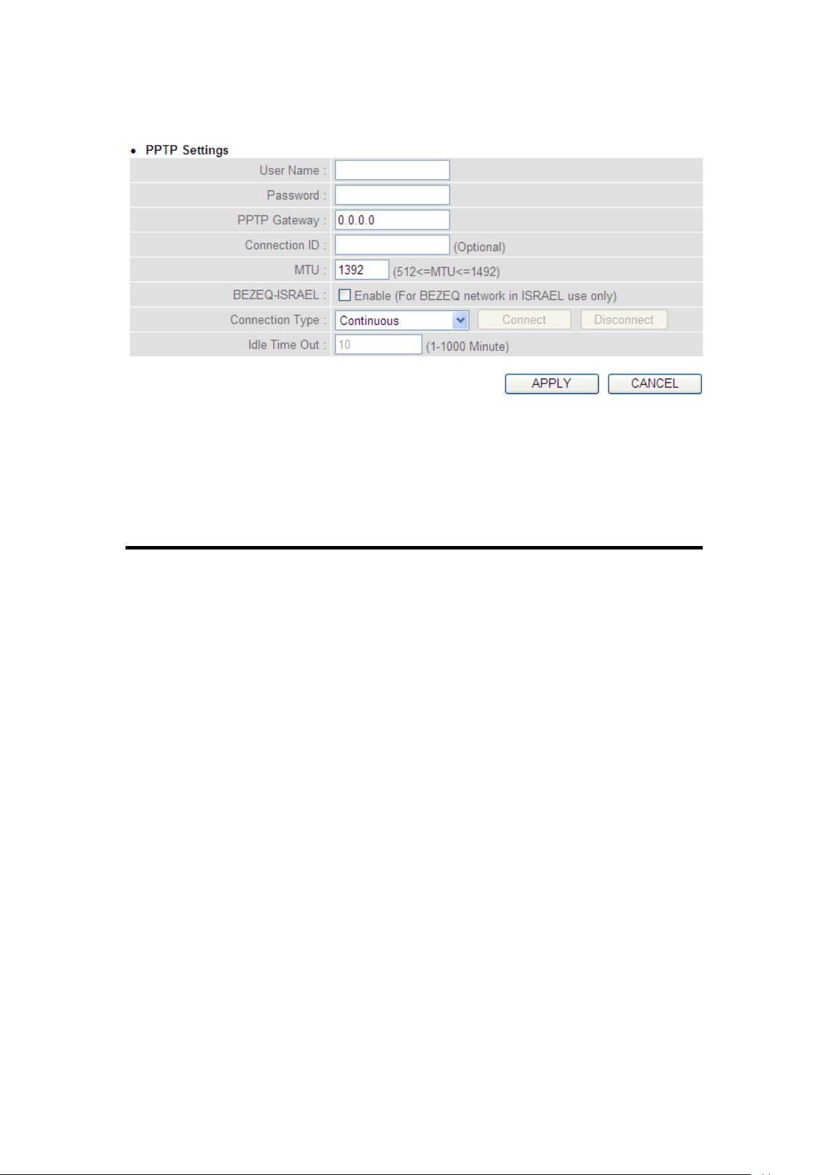
1
2
3 4 5 7 8 9 6
Here are descriptions of every setup item:
User Name (1): Input the user ID (user name) assigned by your
Internet service provider.
Password (2): Input the password assigned by your Internet
service provider.
PPTP Gateway (3): Input the IP address of PPTP gateway assigned by
your Internet service provider.
Connection ID (4): Input the connection ID, this is optional and you can
leave it blank.
MTU (5): Input the MTU value of your network connection. If
you don’t know, you can use the default value.
51
Page 53
BEZEQ-ISRAEL (6): If you are connecting to the BEZEQ network in Israel,
enable this function.
Connection Select the type of Internet connection you
type (7): wish to use, refer to section 2-5-2 for detailed
descriptions.
Idle Time Out (8): Input the idle time out of Internet connection you
wish to use, and refer to section 2-5-2 for detailed
descriptions.
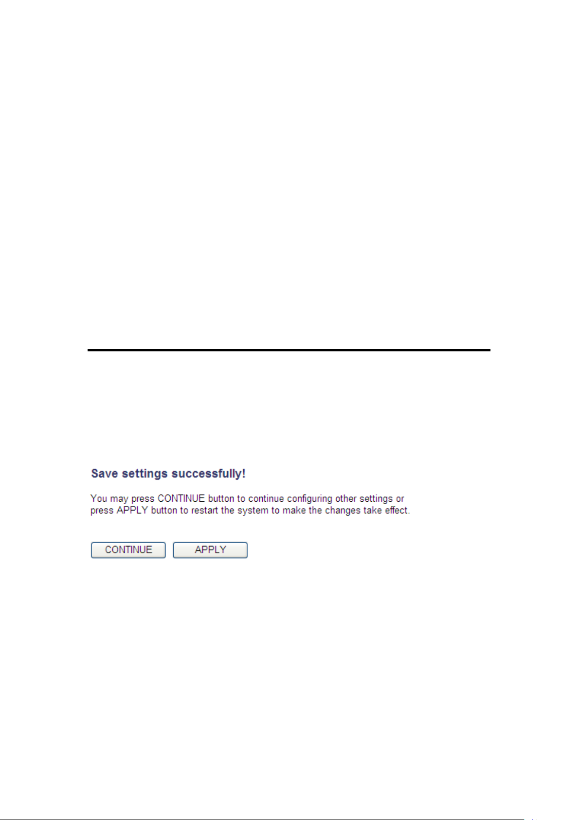
When you complete all settings, click the ‘Apply’ (9) button and the
following will be displayed on your web browser:
Click the ‘Continue’ button to go back to the previous setup menu; to
continue on other setup procedures, or click the ‘Apply’ button to
reboot the router so the settings will take effect (wait for about 60
seconds while router is rebooting).
If you want to reset all settings in this page back to previously-saved
values, click the ‘Cancel’ button.
52
Page 54
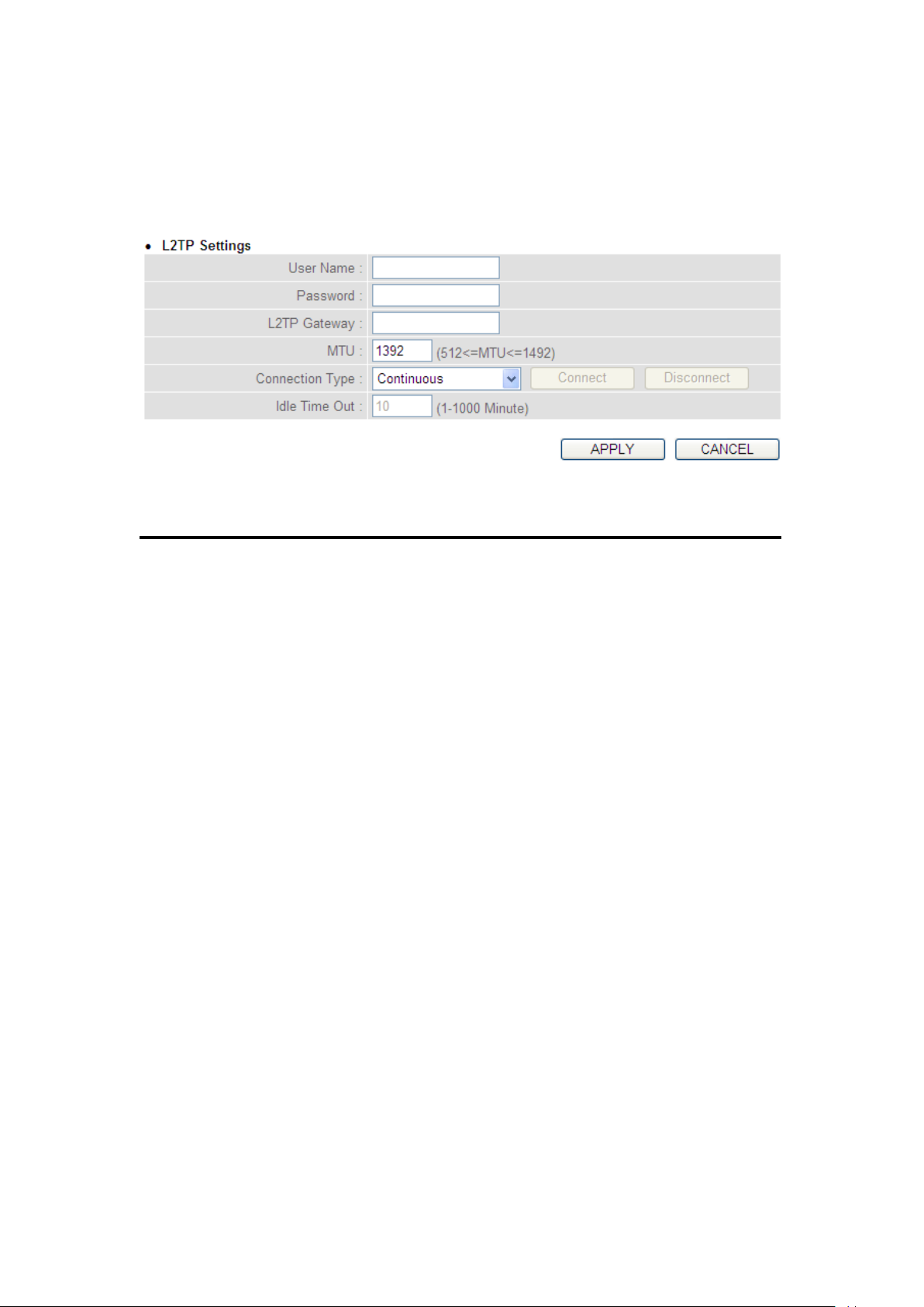
1
2
4
3
5
7
6
2-5-5 Setup procedure for ‘L2TP’:
Here are descriptions of every setup item:
User ID (1): Input the user ID (user name) assigned by your Internet
service provider.
Password (2): Input the password assigned by your Internet service
provider.
L2TP Input the IP address of L2TP gateway
Gateway (3): assigned by your Internet service provider.
MTU (4): Input the MTU value of your network connection. If you
don’t know, you can use the default value.
Connection Select the type of Internet connection
type (5): you wish to use, refer to section 2-5-2 for detailed
descriptions.
53
Page 55
Idle Time Input the idle time out of Internet connection
Out (6): you wish to use, and refer to section 2-5-2 for detailed
descriptions.
When you complete all settings, click the ‘Apply’ (7) button and the
following will be displayed on your web browser:
Click the ‘Continue’ button to go back to the previous setup menu; to
continue on other setup procedures, or click the ‘Apply’ button to
reboot the router so the settings will take effect (wait for about 60
seconds while the router is rebooting).
If you want to reset all the settings in this page back to previously-saved
values, click the ‘Cancel’ button.
54
Page 56
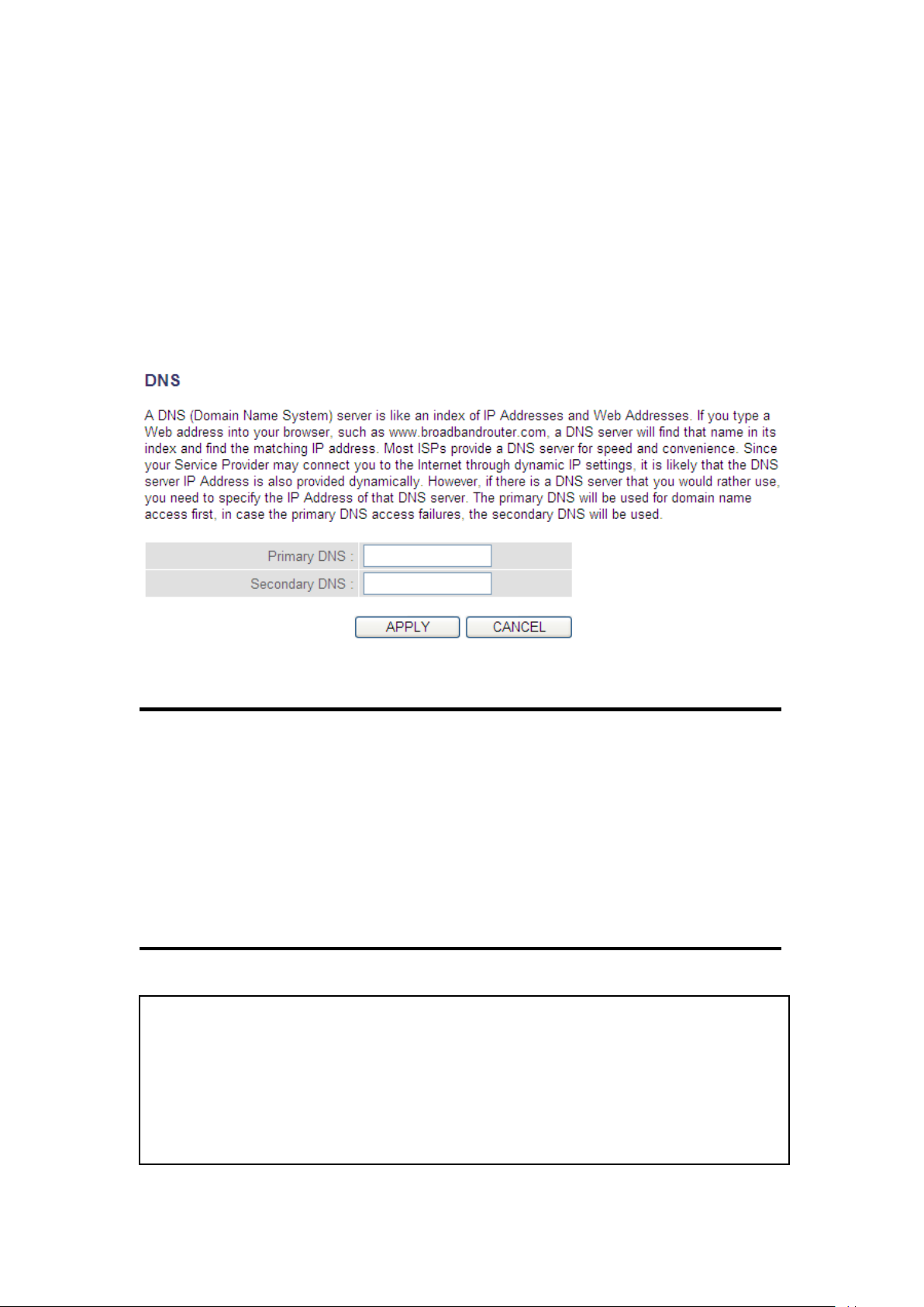
2-5-6 Setup procedure for ‘DNS’:
NOTE: Only the IP address can be inputted here; DO NOT use the hostname
of the DNS server! (i.e. only numeric characters and dots are accepted)
10.20.30.40……………………………………………………………… Correct
dns.serviceprovider.com…………………………………………... Incorrect
1
2
3
If you select ‘Dynamic IP’ or ‘PPPoE’ as the Internet connection method,
at least one DNS server’s IP address should be assigned automatically.
However, if you have a preferred DNS server, or your service provider
didn’t assign the IP address of the DNS server for any reason, you can
input the IP address of the DNS server here.
Here are descriptions of every setup item:
DNS Address (1): Input the IP address of the DNS server provided by
your service provider.
Secondary Input the IP address of another DNS
DNS Address (2): server provided by your service provider. This is
optional.
55
Page 57
After you complete all settings, click the ‘Apply’ (3) button and the
following will be displayed on your web browser:
Click the ‘Continue’ button to go back to the previous setup menu; to
continue on other setup procedures, or click the ‘Apply’ button to
reboot the router so the settings will take effect (wait for about 60
seconds while the router is rebooting).
If you want to reset all the settings in this page back to previously-saved
values, click the ‘Cancel’ button.
56
Page 58
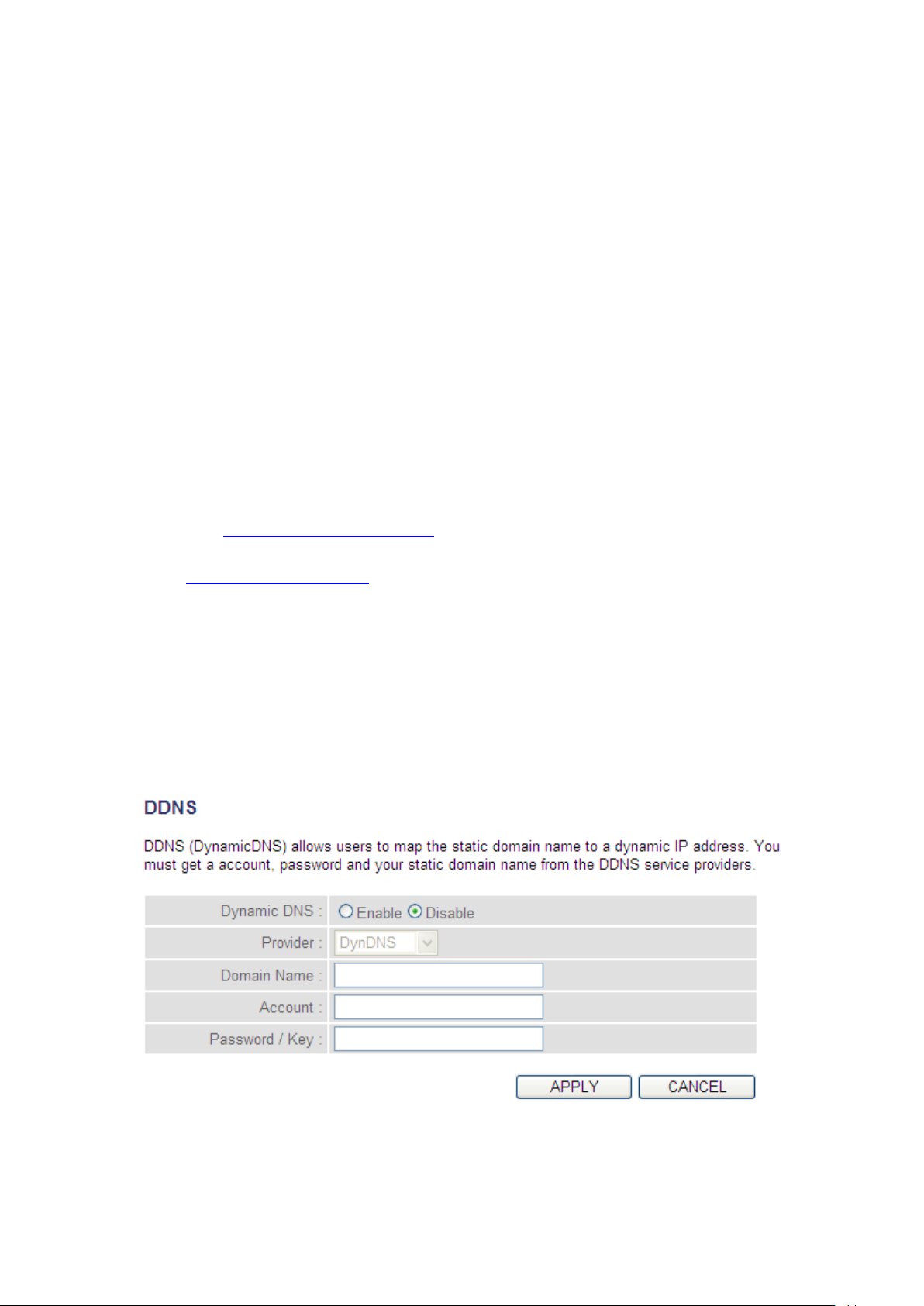
2-5-7 Setup procedure for ‘DDNS’:
1
2
3
4
5
6
DDNS (Dynamic DNS) is an IP-to-Hostname mapping service for Internet
users who don’t have a static (fixed) IP address. Problems will occur
when user(s) want to provide services to other users on the Internet, as
their IP address will vary every time when connected to the Internet.
This router supports the DDNS service of several service providers, for
example:
DynDNS (http://www.dyndns.org)
TZO (http://www.tzo.com)
Go to one of the DDNS service provider’s WebPages listed above, and
get a free DDNS account by following the instructions given on their
webpage.
Here are descriptions of every setup item:
57
Page 59
Dynamic DNS (1): If you want to enable the DDNS function, select
‘Enabled’; otherwise select ‘Disabled’.
Provider (2): Select your DDNS service provider.
Domain Name (3): Input the domain name you’ve obtained from the
DDNS service provider.
Account / Input account or email of DDNS registration.
E-Mail (4):
Password / Key (5): Input the DDNS service password or key.
After you complete all settings, click the ‘Apply’ (6) button and the
following will be displayed on your web browser:
Click the ‘Continue’ button to go back to the previous setup menu; to
continue on other setup procedures, or click the ‘Apply’ button to
reboot the router so the settings will take effect (wait for about 60
seconds while router is rebooting).
If you want to reset all the settings in this page back to previously-saved
values, click the ‘Cancel’ button.
58
Page 60
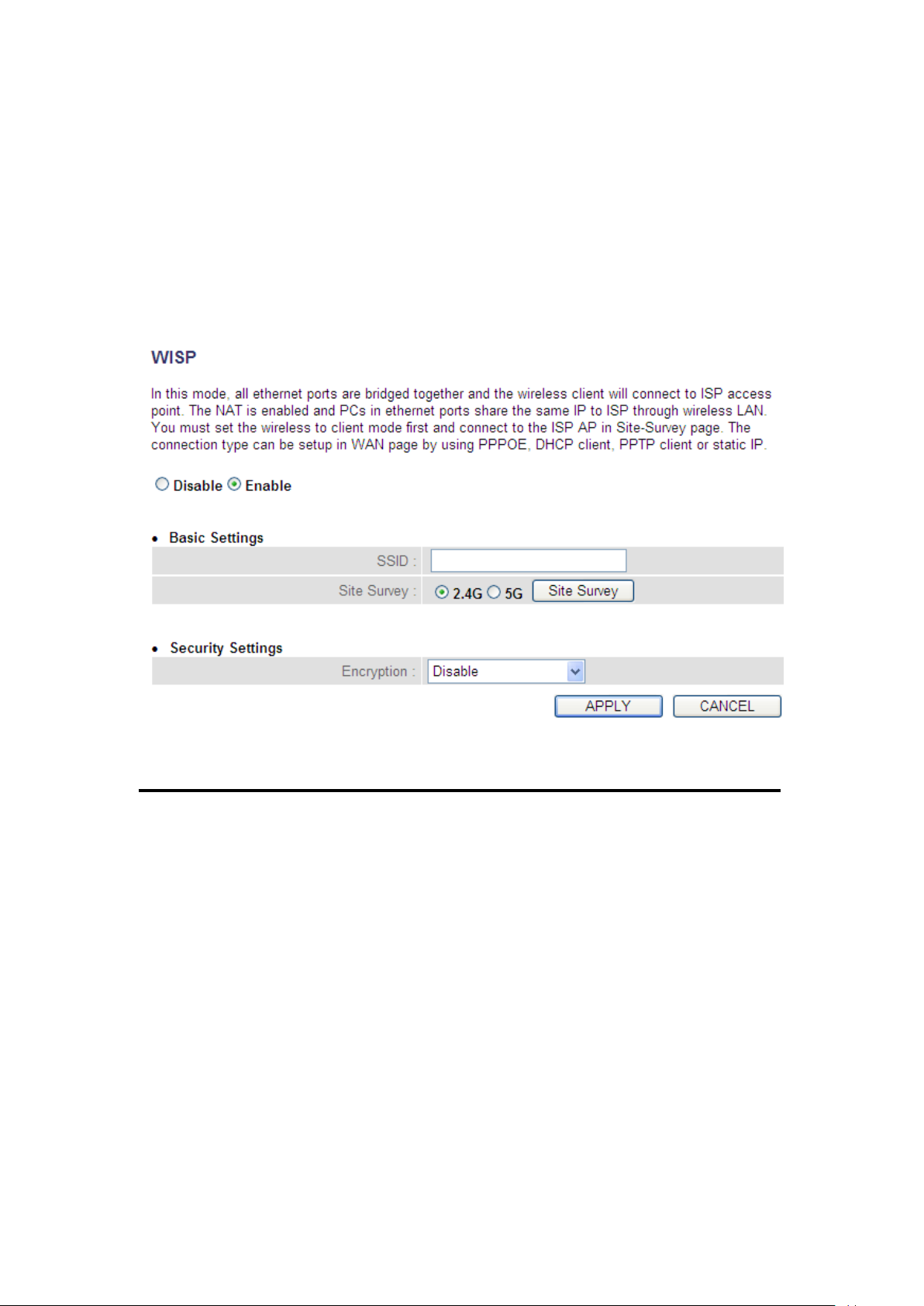
2-5-8 Setup procedure for ‘WISP’:
1
2
3
4
5
If the network service provided by your service provider is through a
wireless network, select this mode. After you have connected the router
to the access point of the service provider wirelessly, set up the WAN
connection type in the WAN page.
Here are descriptions of every setup item:
Disable/Enable (1): There are three selections for wireless ISP
functions.
Disable: disables this function.
Enable: enables this function and the router can
connect to the access points installed by your
wireless service provider. Any clients associated
with the router can access the Internet service
through the wireless network.
59
Page 61

Note: In this mode, if you are informed by your
wireless ISP that the wireless settings of the
access point have changed, configure the router in
this page to match the settings.
SSID (2): This is the name of the wireless network. Input the
SSID name that your ISP provided to you.
Site Survey (3): Click the ‘Select Site Survey’ button, then a
“Wireless Site Survey Table” will pop up. It will list
all available access points nearby. Select the access
point designated by your wireless ISP in the table
and the router will join the wireless network
through this access point.
Encryption (4): If the access point enables wireless security, you have to
follow the same settings in order to access the
access point. Click to set security settings for this
connection (go to section ‘2-7-3 Wireless Security’
for detailed instructions).
After you complete all settings, click the ‘Apply’ (5) button and the
following will be displayed on your web browser:
60
Page 62

Click the ‘Continue’ button to go back to the previous setup menu; to
continue on other setup procedures, or click the ‘Apply’ button to
reboot the router so the settings will take effect (wait for about 60
seconds while router is rebooting).
If you want to reset all the settings in this page back to previously-saved
values, click the ‘Cancel’ button.
61
Page 63
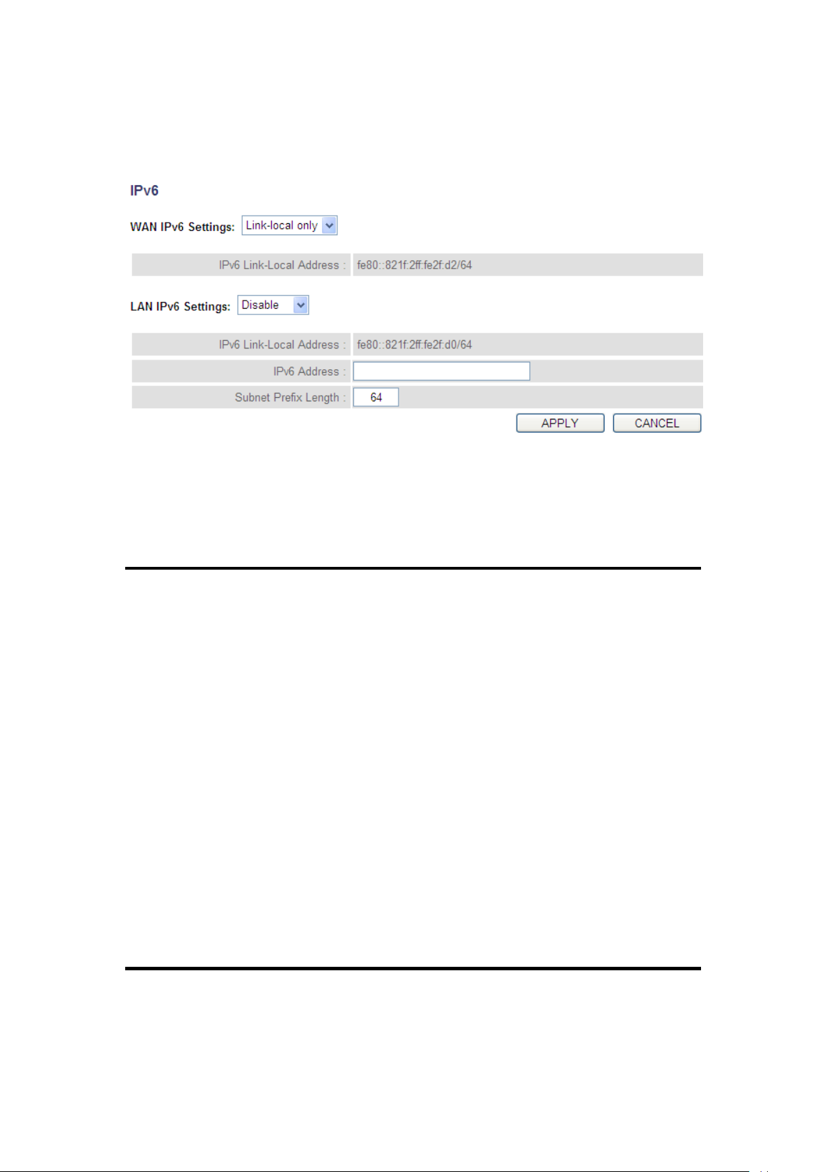
2-5-9 Setup procedure for ‘IPv6’:
1
2
3 4 5
Here are descriptions of every setup item:
WAN IPv6 Settings (1): Select the required transition mechanism
as assigned by your service provider.
LAN IPv6 Settings (2): Select the auto configuration method for
IPv6.
IPv6 Address (3): Input the IPv6 address for the LAN port.
Subnet Prefix Length (4): Default is set at 64. Only change if
required to do so by your ISP.
62
Page 64
After you complete all settings, click the ‘Apply’ (5) button and the
following will be displayed on your web browser:
Click the ‘Continue’ button to go back to the previous setup menu; to
continue on other setup procedures, or click the ‘Apply’ button to
reboot the router so the settings will take effect (wait for about 60
seconds while the router is rebooting).
If you want to reset all the settings in this page back to previously-saved
values, click the ‘Cancel’ button.
63
Page 65

2-6 Wired LAN Configurations
Suggestions on IP address numbering plan:
If you have no idea on how to define an IP address plan for your
network, here are some suggestions.
1. A valid IP address has 4 fields: a.b.c.d, for most home and company
users, it’s suggested to use 192.168.c.d, where c is an integer
between 0 and 254, and d is an integer between 1 and 254. This
router is capable of working with up to 253 clients, so you can set
the ‘d’ field of IP address of router as 1 or 254 (or any number
between 1 and 254), and pick a number between 0 and 254 for field
‘c’.
2. In most cases, you should use ‘255.255.255.0’ as the subnet mask,
which allows up to 253 clients (this also meets the router’s
capability of working with up to 253 clients).
3. For all servers and network devices which will provide services to
other people (like Internet service, print service, and file service),
they should use a static IP address. Give each of them a unique
Before all computers using wired Ethernet connections (i.e. those
computers that connect to this router’s LAN port 1 to 4 by Ethernet
cable) can communicate with each other and access the Internet, they
must have a valid IP address.
There are two ways to assign IP addresses to computers: static IP
address (set the IP address for every computer manually), and dynamic
IP address (IP addresses of computers will be assigned by the router
automatically.
It’s recommended for most of computers to obtain an IP address
automatically, as it will save a lot of time on setting IP addresses for
every computer. For servers and network devices which will provide
services to other computers and users that come from Internet, a static
IP address should be used, so other computers can locate the server.
64
Page 66

Follow the instructions below to set wired LAN parameters:
Click the ‘LAN’ menu on the left of the web management interface, there
are three setup groups here: ‘LAN IP’, ‘DHCP Server’, and ‘Static DHCP
Leases Table’. Below are the setup instructions for each of them:
2-6-1 LAN IP section:
65
Page 67
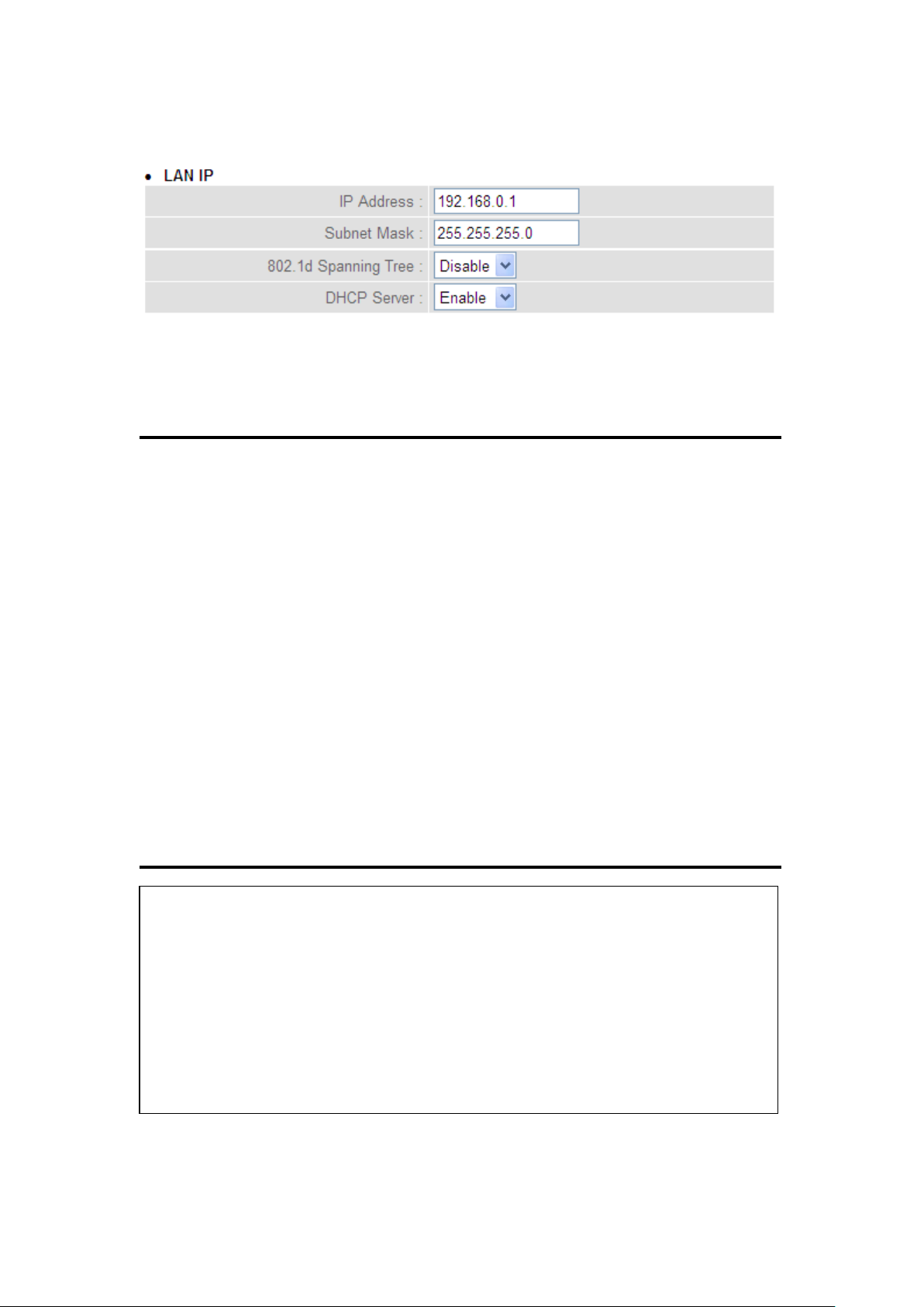
Recommended Values if you don’t know what to fill:
IP Address: 192.168.0.1
Subnet Mask: 255.255.255.0
802.1d Spanning Tree: Disable
DHCP Server: Enable
1
3 2 4
Here are descriptions of every setup item:
IP address (1): Input the IP address of this router.
Subnet Mask (2): Input the subnet mask for this network.
802.1d If you wish to activate the 802.1d spanning tree
Spanning Tree (3): function, select ‘Enabled’ for setup item ‘802.1d
Spanning Tree’, or set it to ‘Disabled’
DHCP Server (4): If you want to activate the DHCP server function of
this router, select ‘Enabled’, or set it to ‘Disabled’.
66
Page 68
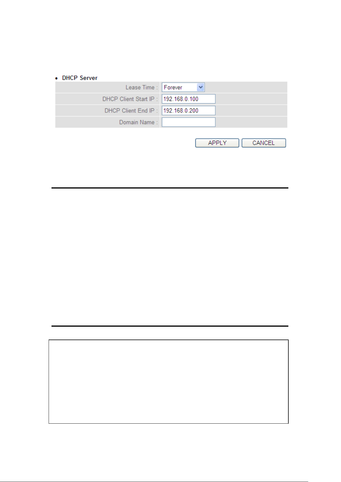
2-6-2 DHCP Server:
Recommended Values if you don’t know what to fill:
Lease Time: Two Weeks (or ‘Forever’, if you have less than 20 computers)
Start IP: 192.168.2.100
End IP: 192.168.2.200
Domain Name: (leave it blank)
1
3 4 2
These settings are only available when the ‘DHCP Server’ in the ‘LAN IP’
section is ‘Enabled’, and here are descriptions of every setup item:
Lease Time (1): Choose a lease time (the duration that every
computer can keep a specific IP address) of every IP
address assigned by this router from the drop-down
menu.
Start IP (2): Input the start IP address of the IP range.
End IP (3): Input the end IP address of the IP range.
Domain Name (4): If you wish, you can also optionally input the
domain name for your network. This is optional.
67
Page 69

NOTE:
1. The number of the last field (mentioned ‘d’ field) of ‘End IP’ must be greater
than the ‘Start IP’, and cannot be the same as the router’s IP address.
2. The former three fields of IP address of ‘Start IP’, ‘End IP’, and ‘IP Address
of ‘LAN IP’ section (mentioned ‘a’, ‘b’, and ‘c’ field) should be the same.
3. These settings will affect wireless clients too.
68
Page 70
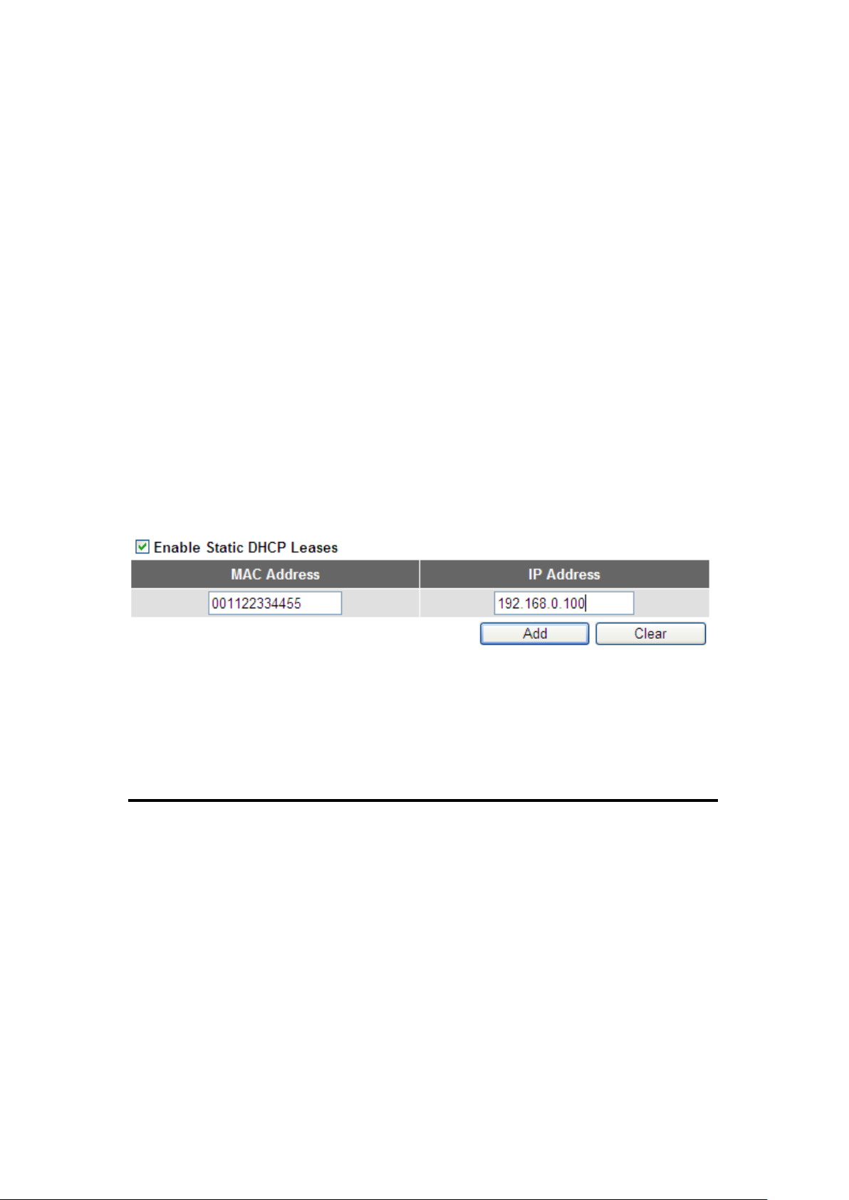
2-6-3 Static DHCP Leases Table:
1 2 3
4
This function allows you to assign a static IP address to a specific
computer forever and still enjoy the benefit of using a DHCP server. A
maximum of 16 static IP addresses can be assigned here.
(If you set the ‘Lease Time’ to ‘forever’ in the ‘DHCP Server’ section,
you can also assign an IP address to a specific computer permanently,
however, you will not be able to assign a certain IP address to a
specific computer, since IP addresses will be assigned in random order
by this way).
Here are descriptions of every setup item:
Enable Static Check this box to enable this function,
DHCP Leases (1): otherwise uncheck it to disable this function.
MAC Address (2): Input the MAC address of the computer or
network device (total 12 characters, with
characters from 0 to 9, and from a to f, like
‘001122aabbcc’)
69
Page 71
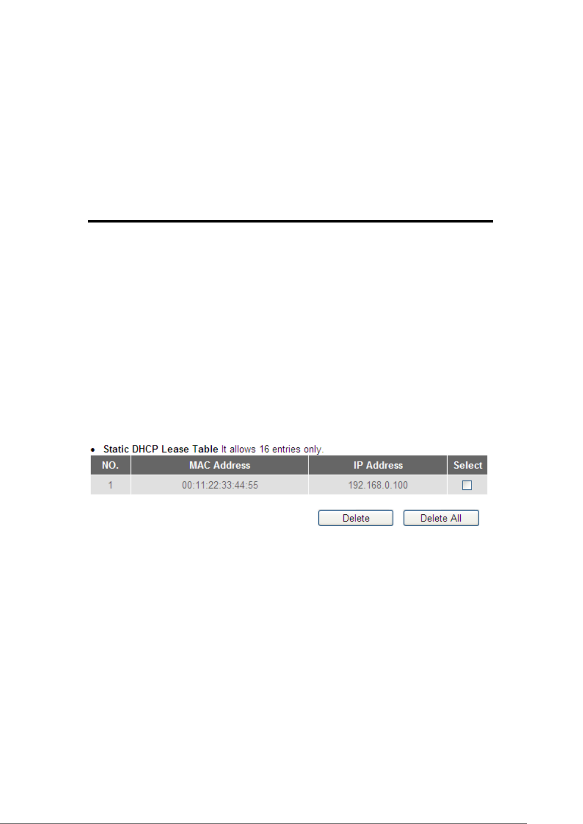
IP address (3): Input the IP address you want to assign to this
1
2
3
computer or network device.
‘Add’ (4): After you inputted the MAC address and IP
address pair, click this button to add the pair to
the static DHCP leases table.
If you want to remove all the characters you just inputted, click the
‘Clear’ button.
After you clicked the ‘Add’ button, the MAC address and IP address
mapping will be added to the ‘Static DHCP Leases Table’ section.
If you want to delete a specific item, check the ‘Select’ box of a MAC
address and IP address mapping (1), then click the ‘Delete’ button (2);
if you want to delete all mappings, click the ‘Delete All’ (3) button.
After you complete all LAN settings, click the ‘Apply’ button on the
bottom of this page. After you click ‘Apply’, the following will be
displayed on your web browser:
70
Page 72

Click the ‘Continue’ button to go back to the previous setup menu; to
continue on router setup, or click the ‘Apply’ button to reboot the router
so the settings will take effect (wait for about 60 seconds while the
router is rebooting).
71
Page 73

2-7 Wireless LAN Configurations
2 1 3
If your computer, PDA, game console, or other network devices are
equipped with a wireless network interface, you can use the wireless
function of this router to allow them connect to the Internet and
share resources with other computers with a wired-LAN connection.
You can also use the built-in security functions to protect your
network from being attacked by malicious intruders.
Follow these instructions to set wireless parameters:
Click the ‘Wireless’ menu at the top of the web management interface,
and the following will be displayed on your web browser. You must
enable the wireless function of this router, or the wireless interface of
this router will not function. Select ‘Enable’ (1), then click the ‘Apply’ (2)
button.
If you’re coming here because you want to disable the wireless function,
select ‘Disable’ (3), then click the ‘Apply’ (2) button.
After you click the ‘Apply’ (2) button, the following will be displayed on
your web browser:
72
Page 74
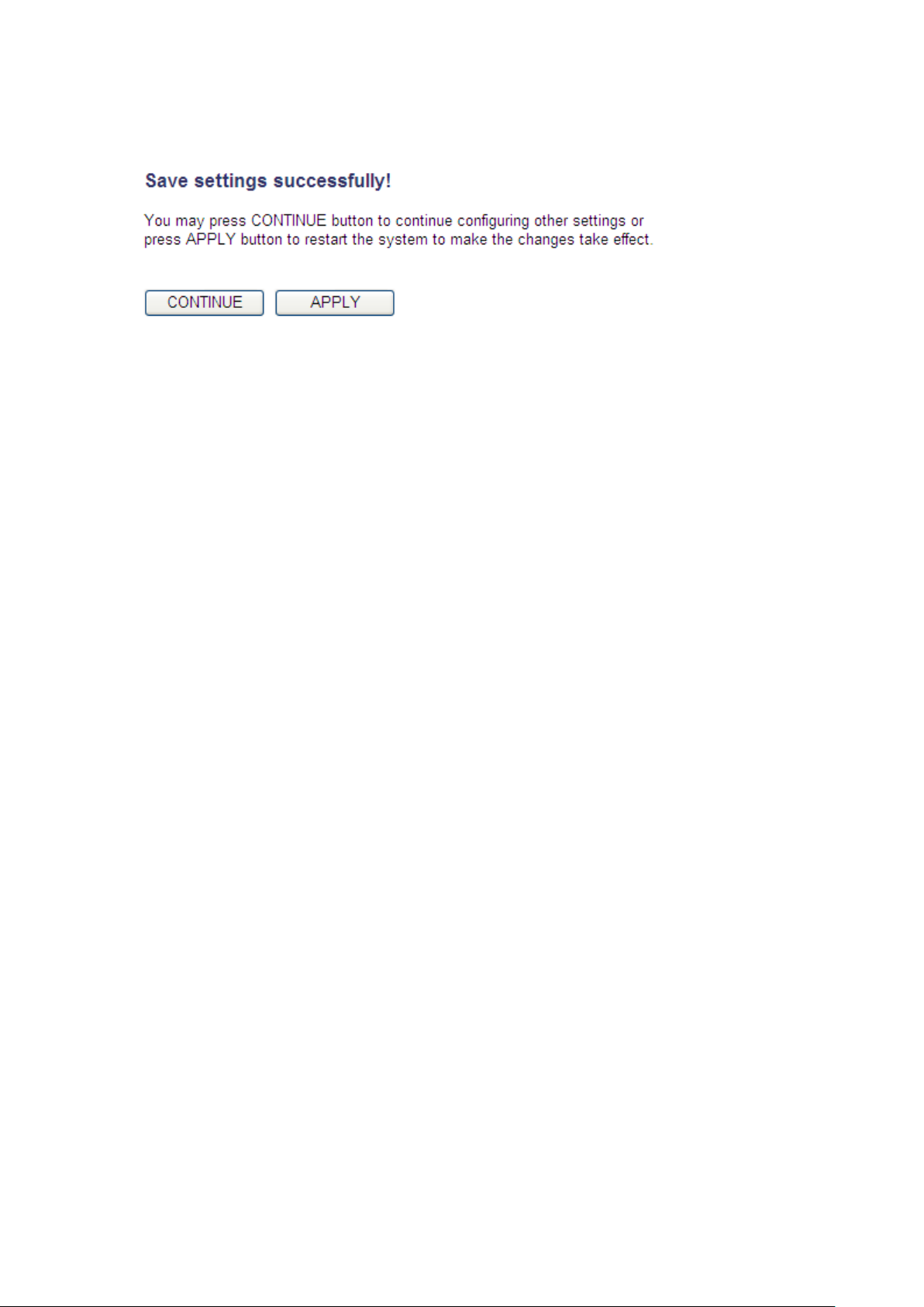
Click the ‘Continue’ button to go back to the previous setup menu; to
continue on other setup procedures, or click the ‘Apply’ button to
reboot the router so the settings will take effect (wait for about 60
seconds while router is rebooting).
73
Page 75
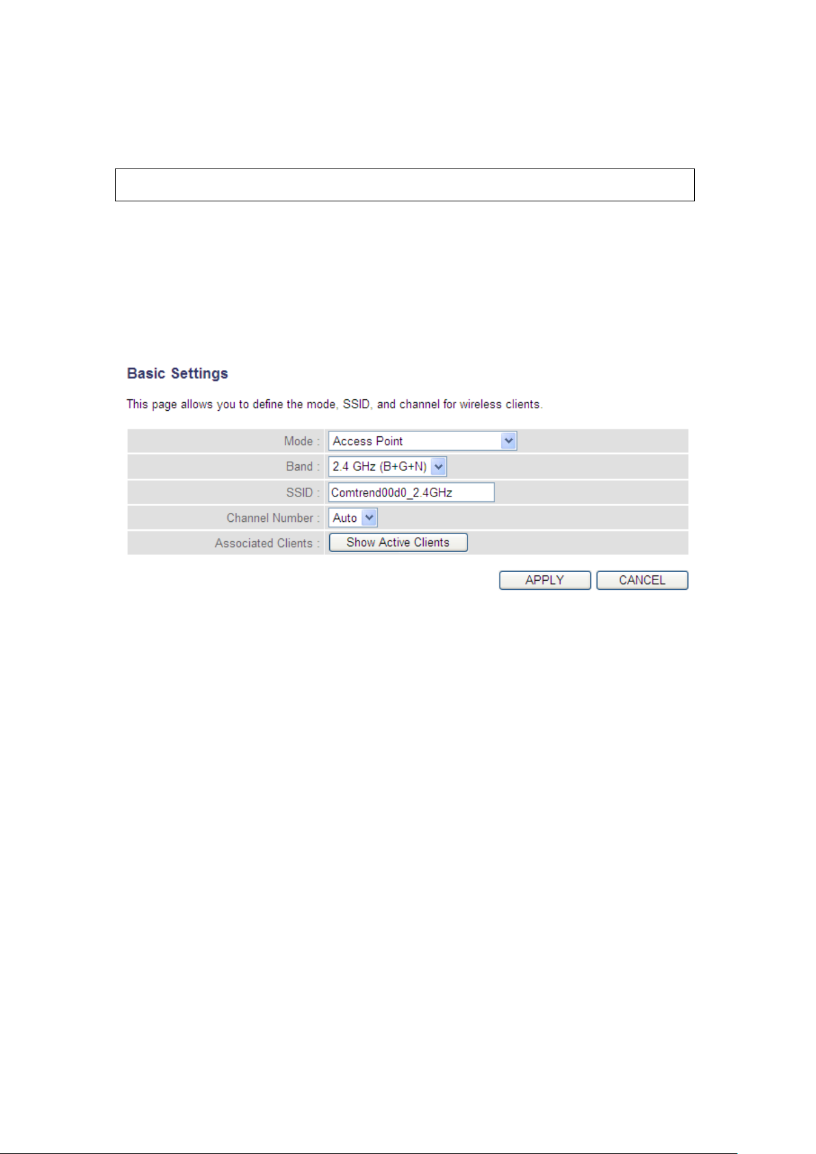
2-7-1 Basic Wireless Settings
Note : The descriptions below are also applicable to the 5 GHz band
Click the ‘Wireless’ menu on the upper-right side of the web
management interface, then click ‘Basic Settings’, and the following will
be displayed on your web browser:
This wireless router can work in 6 modes:
a. Access Point: Standard wireless AP .
b. Station-Infrastructure: Configure the router to an Ethernet device
such as TV, Game player, HDD&DVD to enable the Ethernet device to be
a wireless station.
c. AP Bridge-Point to Point: Connect this router with another wireless
router, to expand the scope of the network.
74
Page 76

d. AP Bridge-Point to Multi-Point: Connect this router with up to four
NOTE: For ‘AP Bridge-Point to Point’ and ‘AP Bridge-Point to Multi-Point’
mode, the wireless router operates in wireless bridge dedicated mode – the
wireless router is only used to expand the scope of the network, and no
wireless clients will be accepted. If you want to use your wireless router to
expand the scope of the network, and also accept wireless clients, please
select ‘AP Bridge-WDS’ or ‘Universal Repeater‘ mode.
other wireless routers, to expand the scope of the network.
e. AP Bridge-WDS: Connect this router with up to four WDS-capable
wireless routers, to expand the scope of the network.
f. Universal Repeater: The router can act as Station and an AP at the
same time. It can use the Station function to connect to a Root AP and
use the AP function to service all wireless stations within its coverage.
Select the operation mode you want to use from the ‘Mode’ drop-down
menu (1), and continue on other operation mode specific settings:
AP - go to section 2-7-1-1
Station-Infrastructure - go to section 2-7-1-2
AP Bridge-Point to Point - go to section 2-7-1-3
AP Bridge-Point to Multi-Point - go to section 2-7-1-4
AP Bridge-WDS - go to section 2-7-1-5
Universal Repeater - go to section 2-7-1-6
75
Page 77
2.7.1.1 Setup procedure for ‘Access Point’:
1
2
3
4
5
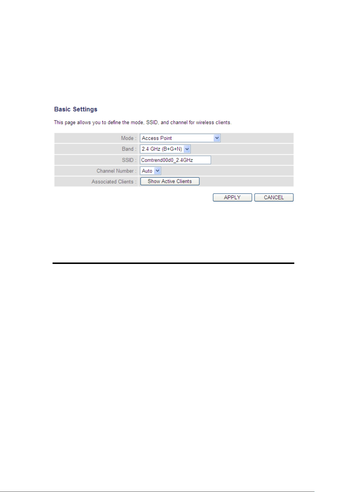
Select Access Point from the ‘Mode’ drop-down menu (1), and the
following will be displayed:
Here are descriptions of every setup item:
Band (2): Select the radio band from one of following options:
76
Page 78

NOTE: For 802.11b and 802.11g mode, the signals can be transmitted only
by antenna 1 (The antenna on the right side of the rear panel).
For 802.11n mode: The router is operating in a 1T2R Spatial Multiplexing
MIMO configuration. 1 antenna is for signal transmitting and 2 antennas are
for signal receiving.
2.4 GHz (B) 2.4GHz band, only allows 802.11b wireless network
clients to connect to this router (maximum transfer
rate 11Mbps).
2.4 GHz (N) 2.4GHz band, only allows 802.11n wireless network
clients to connect to this router (maximum transfer
rate 300Mbps).
2.4 GHz (B+G) 2.4GHz band, only allows 802.11b and 802.11g
wireless network client to connect to this router
(maximum transfer rate 11Mbps for 802.11b clients,
and maximum 54Mbps for 802.11g clients).
2.4 GHz (G) 2.4GHz band, only allows 802.11g wireless network
clients to connect to this router (maximum transfer
rate 54Mbps).
2.4 GHz (B+G+N) 2.4GHz band, allows 802.11b, 802.11g, and
802.11n wireless network clients to connect to this
router (maximum transfer rate 11Mbps for 802.11b
clients, maximum 54Mbps for 802.11g clients, and
maximum 300Mbps for 802.11n clients).
77
Page 79

SSID (3): This is the name of the wireless router. You can type
TIP: You can try to change channel number to another one if you think the
data transfer rate is too slow. There could be some other wireless routers
using the same channel, which will disturb the radio communication
between the wireless client and the wireless router.
NOTE: If you don’t have a special reason to limit the type of allowed
wireless clients, it’s recommended to choose ‘2.4 GHz (B+G+N) to maximize
wireless client compatibility.
any alphanumerical characters here, maximum 32
characters. The SSID is used to identify your own
wireless router from others when there are other
wireless routers in the same area. The default SSID
is ‘default’, it’s recommended to change the default
SSID value to the one which is meaningful to you,
like myhome, office_room1, etc.
Channel Number (4): Select a channel from the drop-down list of
‘Channel Number’, available channel numbers are 1
to 13 for European countries, 1 to 11 for USA. You
can choose any channel number you want to use,
and almost all wireless clients can locate the
channel you’re using automatically without any
problem. However, it’s still useful to remember the
channel number you use, some wireless clients
support manual channel number select, and this
would help in certain scenarios when there is some
radio communication problem.
Associated Clients (5): Click the ‘Show Active Clients’ button, then an
“Active Wireless Client Table” will pop up. You can
see the status of all active wireless stations that are
connecting to the access point.
78
Page 80
2.7.1.2 Setup procedure for ‘Station-Infrastructure’:
1 2 3
4
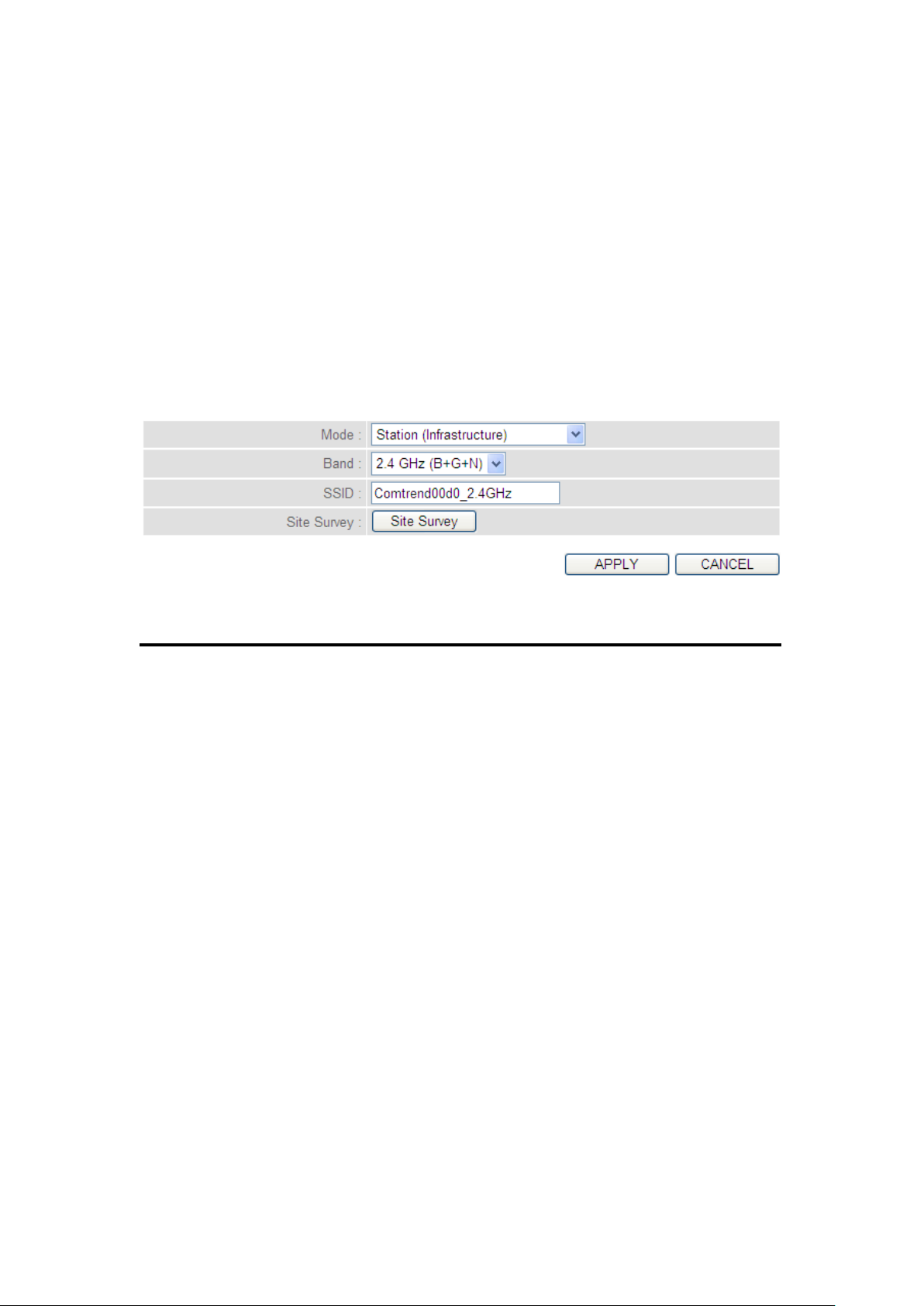
In this mode, you can connect the router to an Ethernet device such as
TV, Game player, HDD&DVD to enable the Ethernet device to be a
wireless station and join a wireless network through an access point or
AP router.
Select Station (Infrastructure) from the ‘Mode’ drop-down menu (1), and
the following will be displayed:
Here are descriptions of every setup item:
Band (2): Select the band you want to use.
SSID (3): This is the name of the wireless network. You can
type the SSID of the network you would like to
connect to.
Site Survey (4): When you use this wireless router as a wireless
station for an Ethernet network device to have
wireless capability, you have to associate it with a
working access point. Click the ‘Select Site Survey’
button, then a “Wireless Site Survey Table” will pop
up. It will list all available access points nearby. You
can select one access point in the table and it will
join the wireless LAN through this access point.
79
Page 81
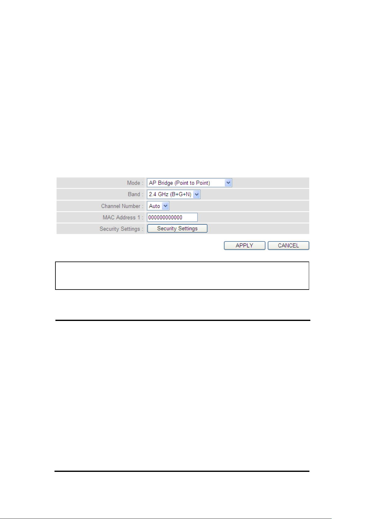
2.7.1.3 Setup procedure for ‘AP Bridge-Point to Point’:
NOTE: The two wireless routers must use the same mode, band, channel
number, and security setting!
1 2 3
4
5
In this mode, you can connect your wireless router with another, to
combine two access points and expand the scope of the wireless
network, and all clients (wired only – AP will not accept wireless clients
in this mode) of the two wireless routers will think they’re on the same
physical network. This function is very convenient when you need to
connect two networks between two buildings.
Select AP Bridge (Point to Point) from the ‘Mode’ drop-down menu (1),
and the following will be displayed:
Here are descriptions of every setup item:
Band (2): Select the band you want to use, the two wireless
routers must use the same setting.
Channel Select the channel you want to use, the two
Number (3): wireless routers must use the same setting.
MAC
address 1(4): Input the MAC address of another wireless router.
Security Click the ‘Security Settings’ button for this
Settings (5): connection.
(Go to section ‘2-7-3 Wireless Security’
for detailed instructions).
80
Page 82
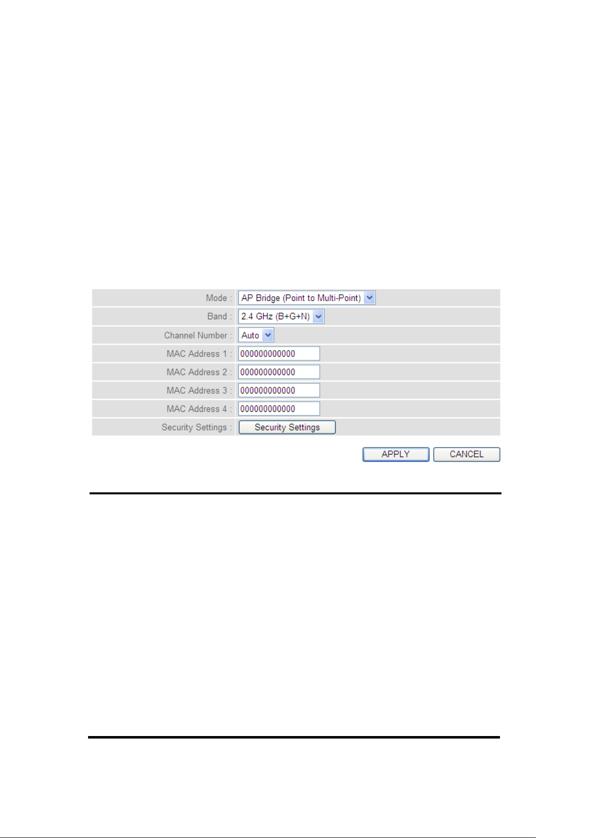
1 2 3
4
5
6
7
8
2.7.1.4 Setup procedure for ‘AP Bridge-Point to Multi-Point’:
In this mode, you can connect your wireless router with at least four
wireless routers to expand the scope of wireless network, and all clients
(wired only – AP will not accept wireless clients in this mode) of the
wireless routers will think they’re on the same physical network.
Select AP Bridge (Point to Multi-Point) from the ‘Mode’ drop-down
menu (1), and the following will be displayed:
Here are descriptions of every setup item:
Band (2): Select the band you want to use, all the wireless
routers must use the same setting.
Channel Select the channel you want to use, all the wireless
Number (3): routers must use the same setting.
MAC address Input the MAC address of the other wireless
1 to 4 (4 - 7): routers.
Security Click the ‘Security Settings’ button for this
Settings (8): connection.
(Go to section ‘2-7-3 Wireless Security’
for detailed instructions).
81
Page 83
1
2
3
4
5
7
8 6 9
10
NOTE: For WDS mode, the output signal nature is the same as that of
normal AP mode.
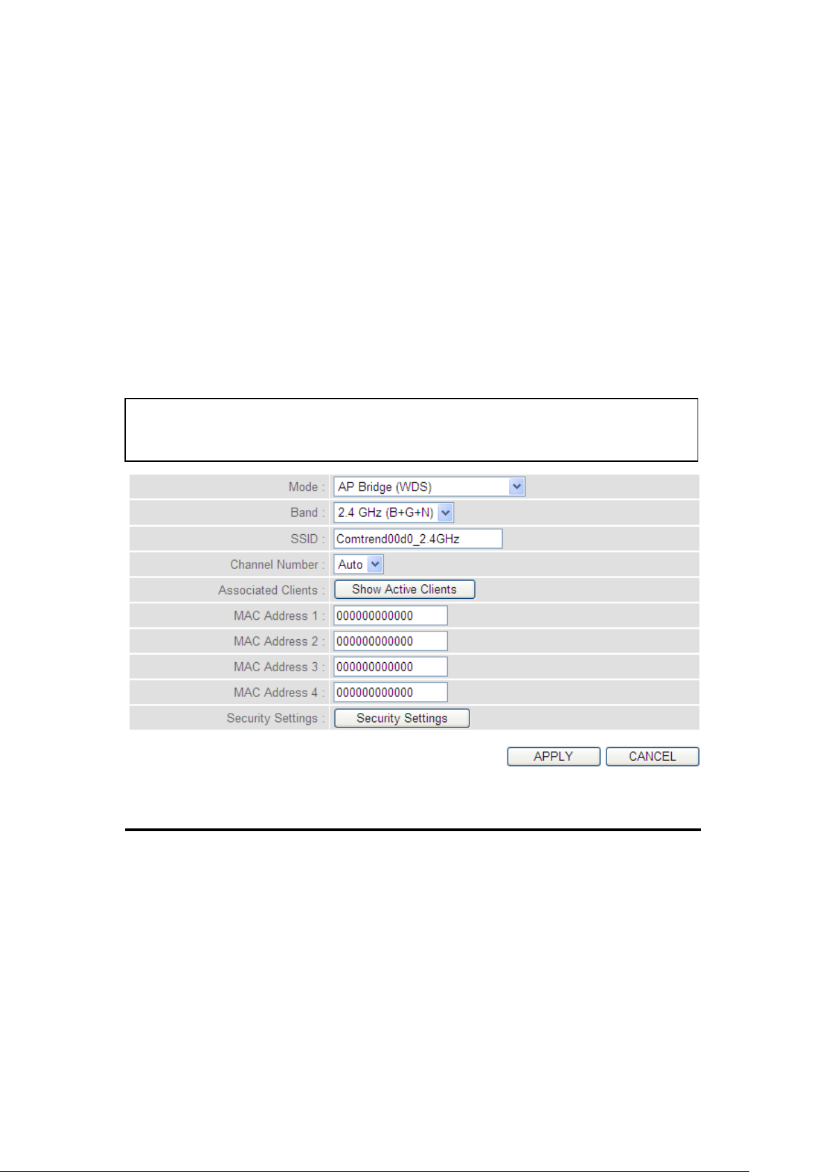
2.7.1.5 Setup procedure for ‘AP Bridge – WDS’
In this mode, you can expand the scope of the network by combining up
to four other access points together, and every access point can still
accept wireless clients.
Select AP Bridge (WDS) from the ‘Mode’ drop-down menu (1), and the
following will be displayed:
Here are descriptions of every setup item:
Band (2): Select the band you want to use, all the wireless
routers must use the same setting.
SSID (3): Input the SSID of your wireless router, the setting
should be the same with other wireless routers for
the convenience of roaming.
82
Page 84

Channel Select the channel you want to use, all the wireless
Number (4): routers must use the same setting.
Associated Clients (5): Click the ‘Show Active Clients’ button, then an
“Active Wireless Client Table” will pop up. You can
see the status of all active wireless stations that are
connecting to the access point.
MAC address Input the MAC address of other wireless routers.
1 to 4 (6 - 9):
Security Click to set the security for this connection
Settings (10): (Go to section ‘2-7-3 Wireless Security’ for detailed
instructions).
83
Page 85
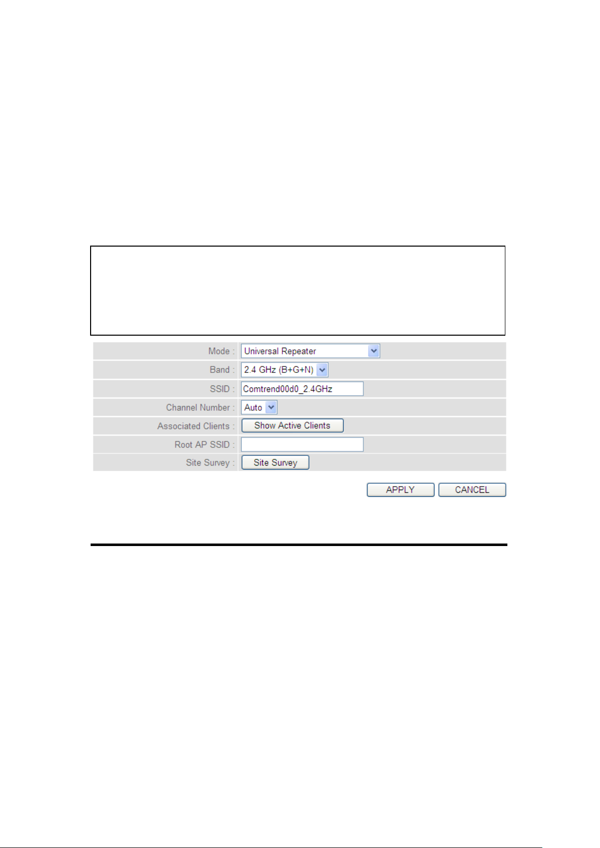
2.7.1.6 Setup procedure for ‘Universal Repeater’
1
2
3
4
5
7
6
NOTE: For Repeater Mode, this router will demodulate the received signal,
checking if this signal is noise for the operating network then have the
signal modulated and amplified again. The output power of this mode is the
same as that of WDS and normal AP mode.
In this mode, the router can act as a wireless repeater; it can be a
Station and an AP at the same time. It can use the Station function to
connect to a Root AP and use the AP function to service all wireless
stations within its coverage.
Select Universal Repeater from the ‘Mode’ drop-down menu (1), and the
following will be displayed:
Here are descriptions of every setup item:
Band (2): Select the band you want to use, all the wireless
routers must use the same setting.
SSID (3): This is the name of the wireless router. You can type
any alphanumerical characters here, maximum 32
characters. SSID is used to identify your own
wireless router from others when there are other
wireless routers in the same area. Default SSID is
‘default’, it’s recommended to change default SSID
value to the one which is meaningful to you, like
myhome, office_room1, etc.
84
Page 86
Channel Select the channel you want to use, all the wireless
Number (4): clients must use the same setting.
Associated Clients (5): Click the ‘Show Active Clients’ button, then an
“Active Wireless Client Table” will pop up. You can
see the status of all active wireless stations that are
connecting to the access point.
Root AP SSID (6): In ‘Universal Repeater’ mode, this device can act as
a station to connect to a Root AP. You should assign
the SSID of the Root AP here or click the ‘Select Site
Survey’ button to choose a Root AP.
Site Survey (7): Click the ‘Select Site Survey’ button, then a
“Wireless Site Survey Table” will pop up. It will list
all available access points nearby. You can select
one access point in the table and the router will join
the wireless LAN through this access point.
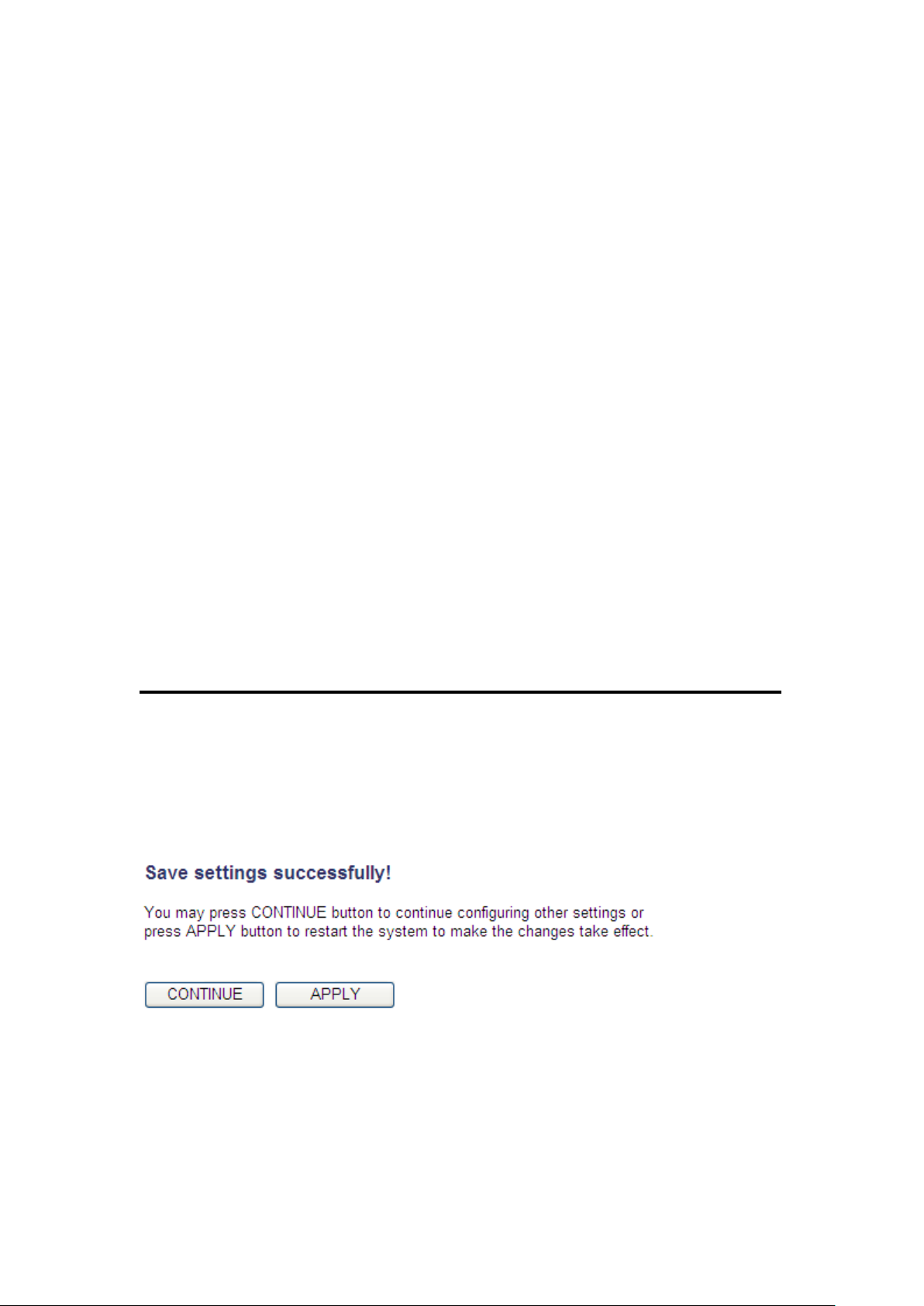
After you complete the wireless settings, click the ‘Apply’ button, after
you click the ‘Apply’ button, the following will be displayed on your web
browser:
Click the ‘Continue’ button to go back to the previous setup menu; to
continue on router setup, or click the ‘Apply’ button to reboot the router
so the settings will take effect (wait for about 60 seconds while router is
rebooting).
85
Page 87
2-7-2 Advanced Wireless Settings
1
2
3
4
5
7
8
6
9
10
11
12
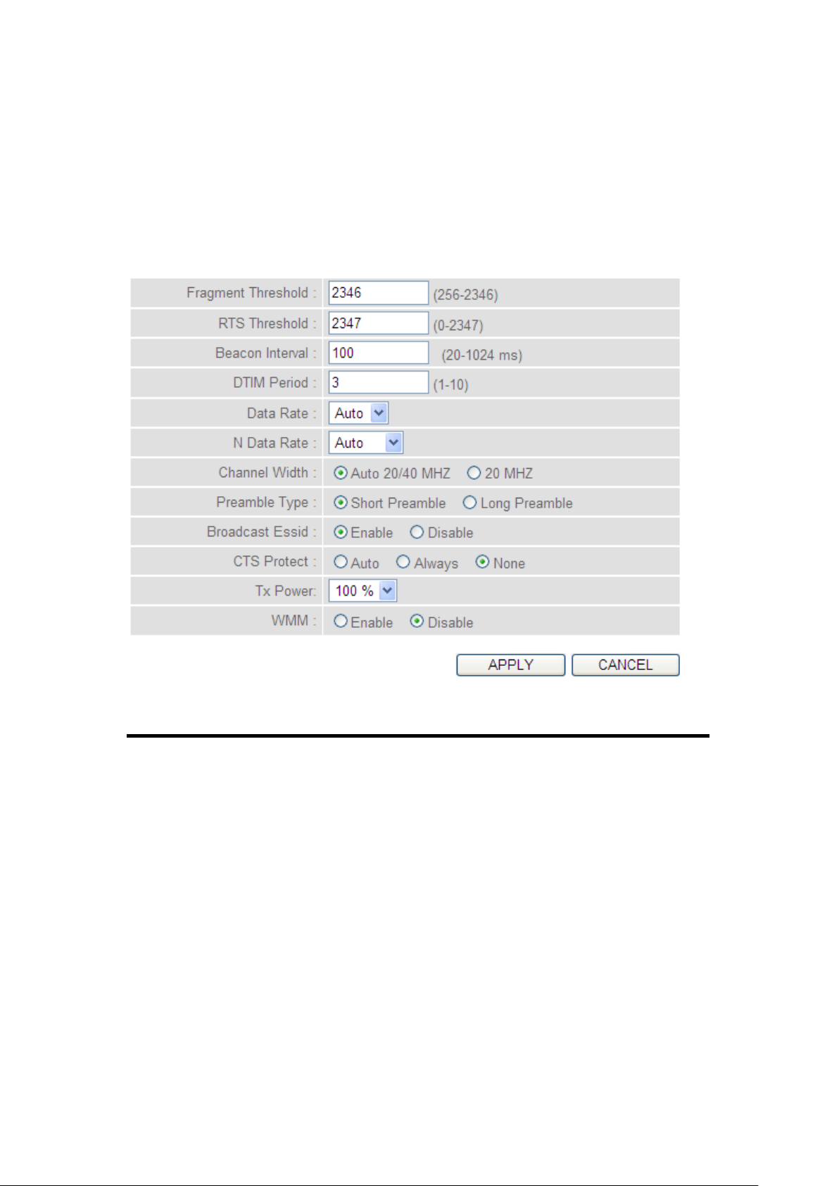
This router provides some advanced control of wireless parameters, if
you want to configure these settings, click the ‘Wireless’ menu on the
upper-right side of the web management interface, then click ‘Advanced
Settings’, and the following will be displayed on your web browser:
Here are descriptions of every setup item:
Fragment The threshold (number of bytes) for the
Threshold (1): fragmentation boundary for directed messages. It is
the maximum data fragment size that can be sent.
Do not modify the default value if you don’t know
what it is, default value is 2346.
RTS Threshold (2): The RTS (Request To Send) threshold parameter
controls what size data packet (number of bytes) the
low level RF protocol issues to an RTS packet. Do
not modify default value if you don’t know what it
is, default value is 2347.
86
Page 88

Beacon Interval (3): The Beacon Interval value indicates the frequency
interval of the beacon. A beacon is a packet
broadcast by the Router to synchronize the
wireless network. Do not modify default value if
you don’t know what it is, default value is 100.
DTIM Period (4): Configures the DTIM (Delivery Traffic Indication
Message) send period. Do not modify the default
value if you don’t know what it is, default value is
3.
Data Rate (5): Set the wireless data transfer rate to a certain value.
Since most of wireless devices will negotiate with
each other and pick a proper data transfer rate
automatically, it’s not necessary to change this
value unless you know what will happen after
modification.
N Data Rate (6): Same as above, but only for 802.11n clients.
Channel Width (7): Set channel width of wireless radio. Do not modify
the default value if you don’t know what it is,
default setting is ‘Auto 20/40 MHz’. 40MHz
provides better network speed for 802.11n wireless
clients. However, if there are 802.11b / g clients
connecting to this Wireless-N Range Extender, it will
switch to 20MHz mode automatically.
87
Page 89

Preamble Type (8): The Preamble type defines the length of the CRC
(Cyclic Redundancy Check) block for
communication between the Access Point and
roaming wireless adapters. Do not modify the
default value if you don’t know what it is, default
setting is ‘Short Preamble’.
Broadcast ESSID (9): Decide if the wireless router will broadcast its own
ESSID or not. You can hide the ESSID of your
wireless router (set the option to ‘Disable’), so only
people those who know the ESSID of your wireless
router can get connected.
CTS Protect (10): Enabling this setting will reduce the chance of radio
signal collisions between 802.11b and 802.11g/n
wireless access points. It’s recommended to set this
option to ‘Auto’ or ‘Always’. However, if you set to
‘None’, your wireless router should be able to work
fine, too.
Tx Power (11): Select the wireless transmitting power level, from
10% to 100%. When wireless clients are not too far
from this Wireless-N Range Extender, you don’t
have to select a higher power level, since this may
cause some individuals to attempt to break into
your wireless network if you have a bad password,
or no password. Select from the drop-down menu.
Default is set at 100%.
88
Page 90
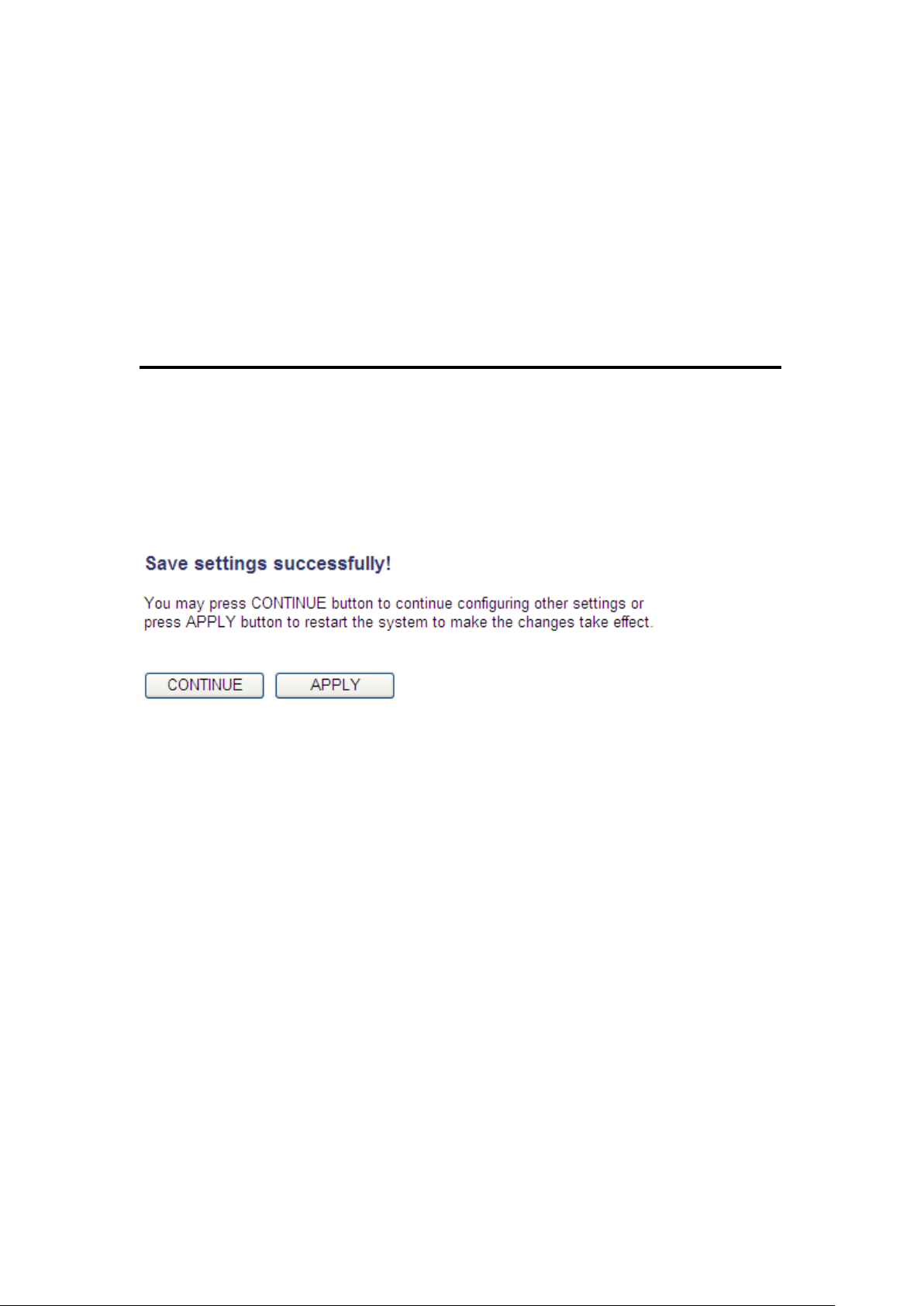
WMM (12): This stands for Wi-Fi MultiMedia, it will enhance
the data transfer performance of multimedia
contents when they’re being transferred over
wireless networks. If you don’t know what it is /
not sure if you need it, it’s safe to set this option to
‘Enable’, however, default value is ‘Disable’.
After you complete these wireless settings, click the ‘Apply’ button ,
and the following will be displayed on your web browser:
Click the ‘Continue’ button to go back to the previous setup menu; to
continue on router setup, or click the ‘Apply’ button to reboot the router
so the settings will take effect (wait for about 60 seconds while the
router is rebooting).
89
Page 91

2-7-3 Wireless Security
It’s very important to set wireless security settings properly! If you
don’t, hackers and malicious users can reach your network and access
valuable data without your consent and this will cause serious security
problems.
To set wireless security settings, click the ‘Wireless’ menu on the
upper-right side of the web management interface, then click ‘Security
Settings’, and follow the instructions to set the wireless security settings:
Select an encryption method from the ‘Encryption’ drop-down menu,
there are four options:
Disable wireless security
When you select this mode, data encryption is disabled, and every
wireless device in proximity will be able to connect to your wireless
router if no other security measure is enabled (like MAC address access
control - see section 2-7-4, or disable ESSID broadcast).
Only use this option when you really want to allow everyone to use
your wireless router, and you don’t care if someone reads the data you
transfer over the network without your consent.
90
Page 92
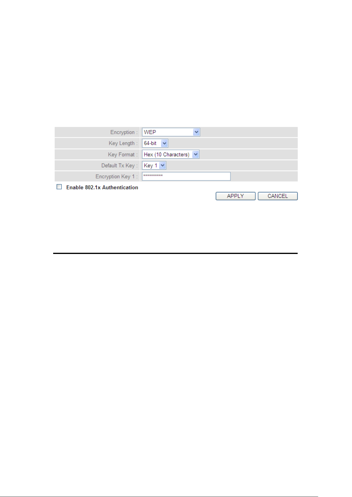
1
2 3 5
4
6
2.7.3.1 WEP - Wired Equivalent Privacy
When you select this mode, the wireless router will use WEP encryption,
and the following setup menu will be shown on your web browser:
Here are descriptions of every setup item:
Key Length (2): There are two types of WEP key length: 64-bit and
128-bit. Using ‘128-bit’ is safer than ’64-bit’, but
will reduce some data transfer performance.
Key Format (3): There are two types of key format: ASCII and Hex.
When you select a key format, the number of
characters of key will be displayed. For example, if
you select ’64-bit’ as key length, and ‘Hex’ as key
format, you’ll see the message at the right of ‘Key
Format’ is ‘Hex (10 characters), which means the
length of WEP key is 10 characters.
91
Page 93
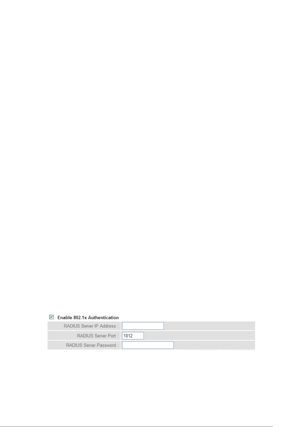
Default Tx Key (4): You can set up to four sets of WEP key, and you can
7 8 9
6
decide which key is being used by default here. If
you don’t know which one you should use, select
‘Key 1’.
Encryption Key Input the WEP key characters here, the number of
1 (5): characters must be the same as the number
displayed in the ‘Key Format’ field. You can use any
alphanumerical characters (0-9, a-z, and A-Z) if you
select ‘ASCII’ key format, and if you select ‘Hex’ as
key format, you can use characters 0-9, a-f, and A-F.
You must input at least one encryption key here,
and if you inputted multiple WEP keys, they should
not be same as each other.
Enable 802.1x IEEE 802.1x is an authentication protocol. Every
Authentication (6): user must use a valid account to login to this
wireless router before accessing the wireless LAN.
The authentication is processed by a RADIUS server.
This mode only authenticates the user by IEEE
802.1x, but it does not encrypt the data during
communication. If there is a RADIUS server in your
environment, enable this function. Check this box
and another sub-menu will appear:
RADIUS Server Input the IP address of the radius
IP address (7): server.
92
Page 94

TIPS: Some examples of WEP key
(Don’t use these examples; use the one of your own!):
ASCII (5 characters): pilot phone 23561 2Hyux #@xmL
ASCII (13 characters): digitalFAMILY 82Jh26xHy3m&n
Hex (10 characters): 287d2aa732 1152dabc85
Hex (26 characters): 9284bcda8427c9e036f7abcd84
To improve the security level, do not use words which can be found in a
dictionary or words too easy to remember! (‘pilot’ and ‘phone’ listed above
are bad examples; just intended to show you what a WEP key looks like).
Wireless clients will remember the WEP key, so you only have to input the
WEP key on the wireless client once, and it’s worth using a complicated
WEP key to improve the security level.
RADIUS Server Input the port number of the radius
Port (8): server.
RADIUS Server Input the port number of the radius
Password (9): password.
After you complete the WEP settings, click the ‘Apply’ button and the
following will be displayed on your web browser:
93
Page 95
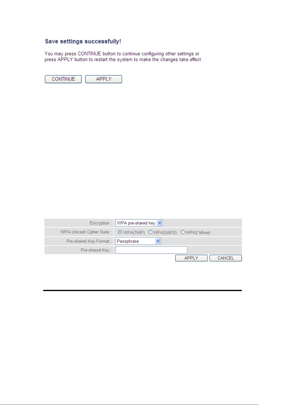
1
2
3
5
4
Click the ‘Continue’ button to go back to the previous setup menu; to
continue on other setup procedures, or click the ‘Apply’ button to
reboot the router so the settings will take effect (wait for about 60
seconds while the router is rebooting).
2.7.3.2 Wi-Fi Protected Access (WPA):
When you select this mode, the wireless router will use WPA encryption,
and the following setup menu will be shown on your web browser:
Here are descriptions of every setup item:
WPA Unicast Select a type of WPA cipher suite.
Cipher Suite (2): Available options are: WPA (TKIP), WPA2 (AES), and
WPA2 Mixed. You can select any one of them, but
you have to make sure your wireless client supports
the cipher you selected.
94
Page 96
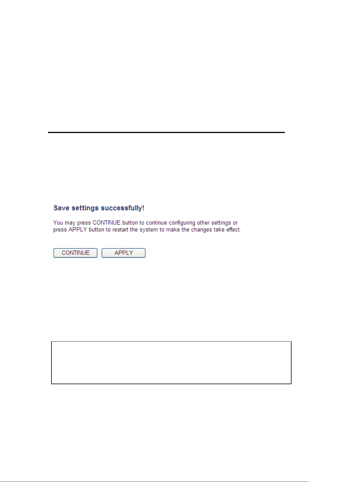
Pre-shared Select the type of pre-shared key, you
NOTE: Some wireless clients (especially those manufactured before 2003)
only support WEP or WPA (TKIP) cipher. A driver upgrade would be needed
for those clients to use WPA and WPA2 encryption.
Key Format (3): can select Passphrase (8 or more alphanumerical
characters, up to 63), or Hex (64 characters of 0-9,
and a-f).
Pre-shared Input the WPA passphrase.
Key (4): It’s not recommended to use a word that can be
found in a dictionary due to security reasons.
After you complete the WPA Pre-shared key settings, click the ‘Apply’
button (5) and the following will be displayed on your web browser:
Click the ‘Continue’ button to go back to the previous setup menu; to
continue on other setup procedures, or click the ‘Apply’ button to
reboot the router so the settings will take effect (wait for about 60
seconds while router is rebooting).
95
Page 97
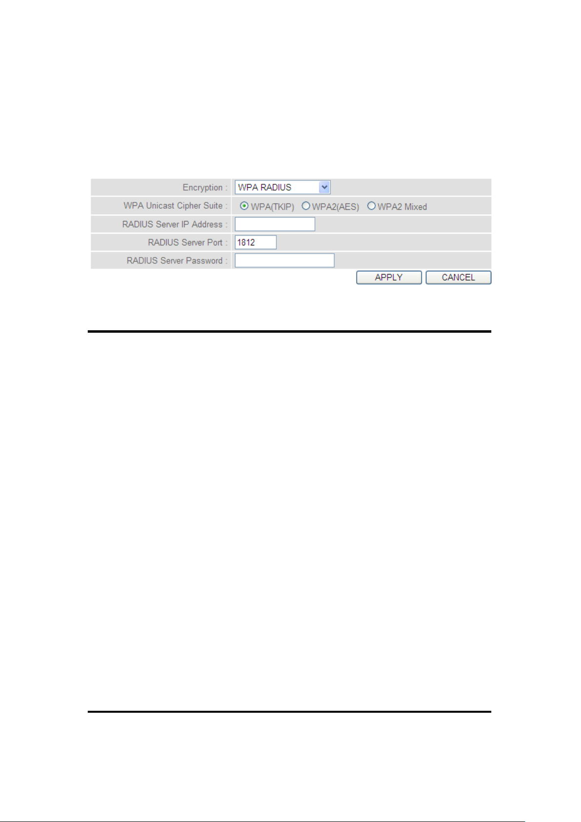
2.7.3.3 WPA RADIUS:
1
3
4
2
5
6
If you have a RADIUS server, this router can work with it and provide
safer wireless authentication.
Here are descriptions of every setup item:
WPA Unicast Select a type of WPA cipher suite.
Cipher Suite (2): Available options are: WPA (TKIP), WPA2 (AES), and
WPA2 Mixed. You can select any one of them, but
you have to make sure your wireless client supports
the cipher you selected.
RADIUS Server Input the IP address of your
IP address (3): Radius authentication server.
RADIUS Server Input the port number of your
Port (4): Radius authentication server. Default setting is
1812.
RADIUS Server Input the password of your Radius
Password (5): authentication server.
96
Page 98
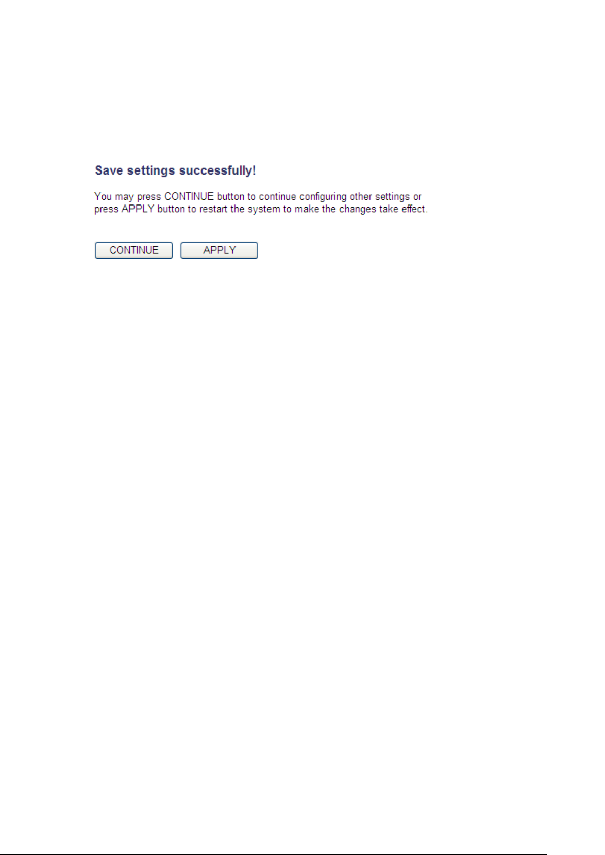
After you complete all settings, click the ‘Apply’ (6) button and the
following will be displayed on your web browser:
Click the ‘Continue’ button to go back to the previous setup menu; to
continue on other setup procedures, or click the ‘Apply’ button to
reboot the router so the settings will take effect (wait for about 60
seconds while router is rebooting).
97
Page 99
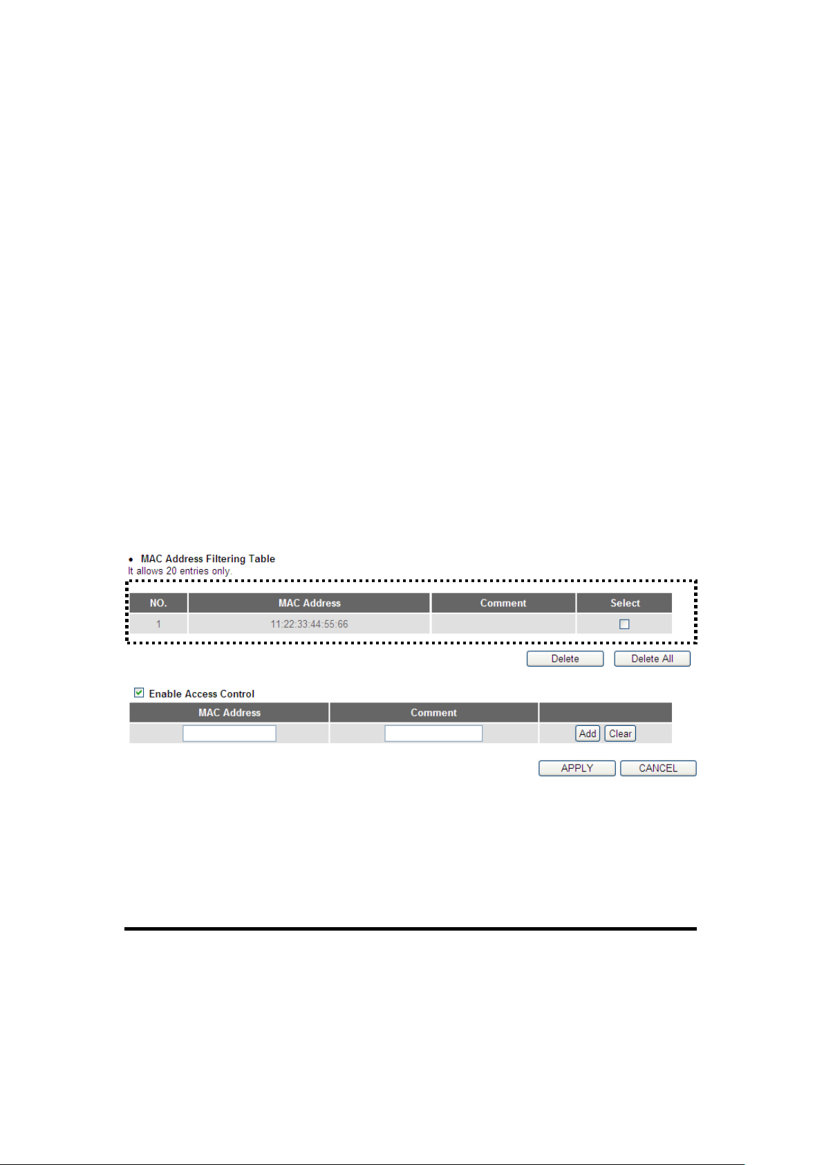
2-7-4 Wireless Access Control
1
2
3
4
6
8
9
5
This function will help you to prevent unauthorized users from
connecting to your wireless router; only those wireless devices who have
the MAC address you assigned here can gain access to your wireless
router. You can use this function with other security measures described
in previous sections, to create a safer wireless environment.
Up to 20 MAC addresses can be assigned by using this function. Click the
‘Wireless’ menu on the upper-right side of the web management
interface, then click ‘Access Control’, and the following will be displayed
on your web browser:
All allowed MAC addresses will be displayed in the ‘MAC Address
Filtering Table’ (1). Here are descriptions of every setup item:
98
Page 100

Delete (2): If you want to delete a specific MAC address entry,
check the ‘select’ box of the MAC address you want
to delete, then click the ‘Delete’ button. (You can
select more than one MAC address).
Delete All (3): If you want to delete all MAC addresses listed here,
click the ‘Delete All’ button.
Enable To enforce MAC address filtering,
Access Control (4): you have to check ‘Enable Wireless Access Control’.
When this item is unchecked, the wireless router
will not enforce MAC address filtering of wireless
clients.
MAC Address (5): Input the MAC address of your wireless devices here,
dash ( - ) or colon ( : ) are not required. (i.e. If the
MAC address label of your wireless device indicates
‘aa-bb-cc-dd-ee-ff’ or ‘aa:bb:cc:dd:ee:ff’, just input
‘aabbccddeeff’.
Comment (6): You can input any text here as the comment of this
MAC address, like ‘ROOM 2A Computer’ or
anything. You can input up to 16 alphanumerical
characters here. This is optional and you can leave it
blank, however, it’s recommended to use this field
to write a comment for every MAC addresses as a
memory aid.
99
 Loading...