

Page 1
1
3
2
5
4
7
6
9
8
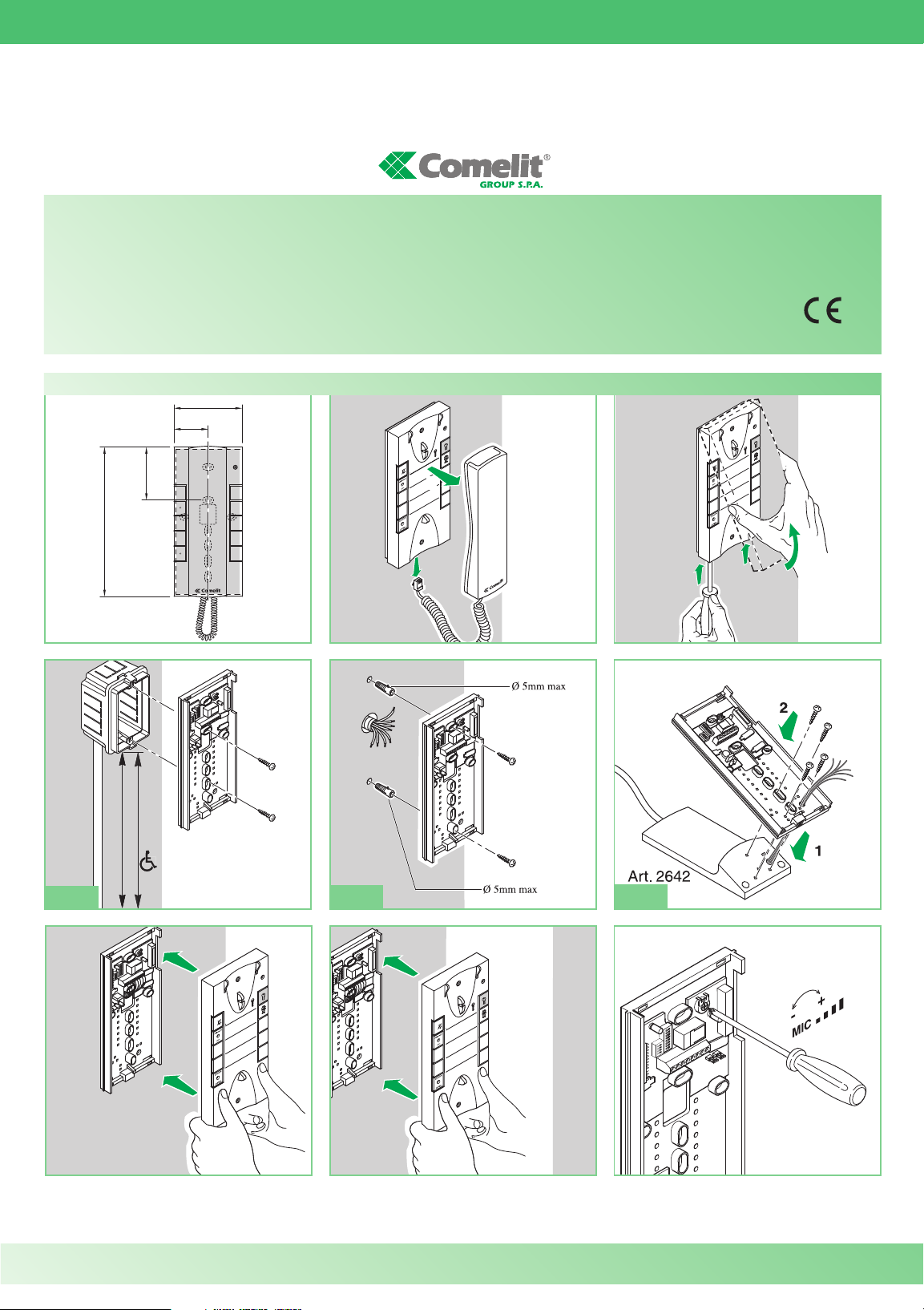
140-145 cm
115-125 cm
95mm
47,5mm
75,5mm
215mm
1
1
3
2
5
4
7
6
9
8
1
2
1
1
3
2
5
4
7
6
9
8
2
1
3
2
5
4
7
6
9
8
TECHNICAL
SHEET
FT 2610SH
Installation Style door-entry phone Art. 2610SH
WARNING
• Install the equipment by carefully following the instructions given by the manufacturer and in compliance with the legislation in force.
• All the equipment must only be used for the purpose it was built for. Comelit Group S. p.A. declines any responsibility for improper use of the apparatus, for modifications made
by others under for whatever reason, and for the use of non-original accessories and materials.
• All the products comply with the requirements of the 2006/95/CE directives (which replace the 73/23/CEE directives and subsequent amendments), as certified by the CE mark
on the products.
• Do not route the riser wires in proximity of the power supply cables (230/400V).
• Do not press and hold the audio catch while the handset is lifted.
A
B
C
Comelit Group UK Ltd - Unit 4 Mallow Park - Watchmead Welwyn Garden City Herts - AL7 1GX - Tel: +44 (0)1707377203 - Fax: +44 (0)1707377204
www.comelitgroup.co.uk www.simplehome.eu info@comelitgroup.co.uk commerciale.italia@comelit.it export.department@comelit.it
Technical service abroad (+39) 0346750092 Export depa rtmet (+39) 0346750093
Page 2
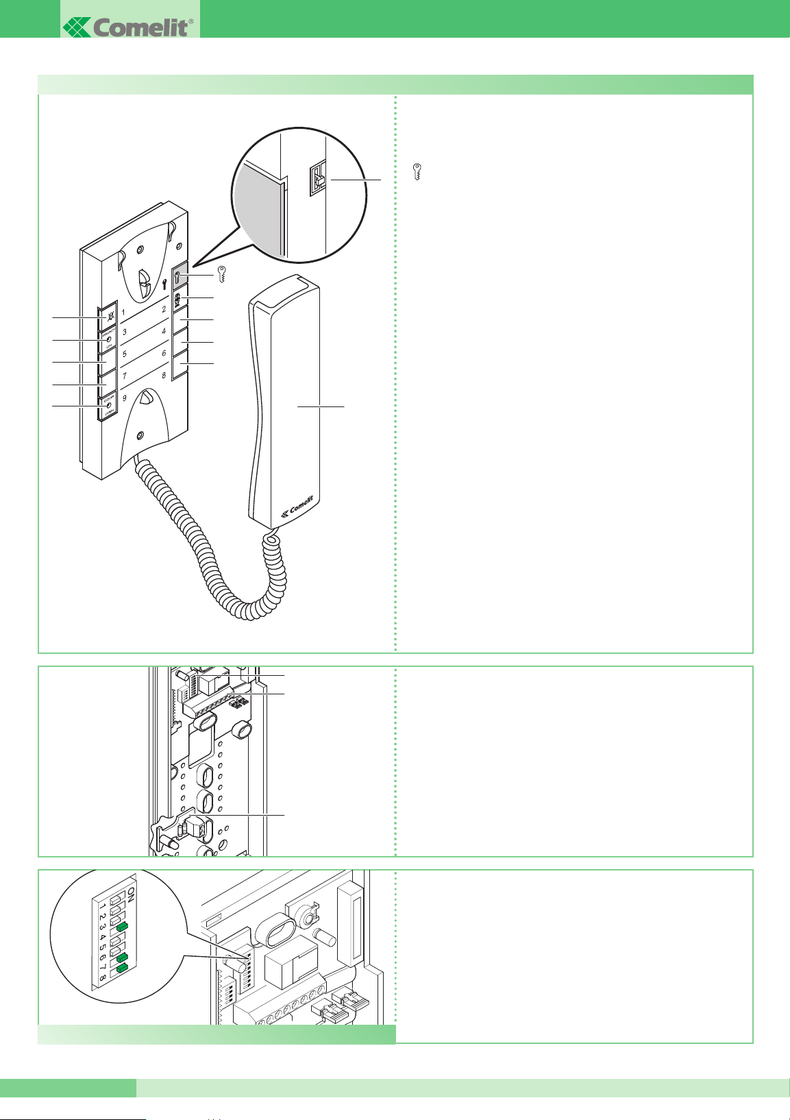
V Ringtone volume switch:
UP position: Maximum volume
Middle position: Minimum volume
DOWN position: Maximum volume
Pushbutton for Door Release
1 Pushbutton for “Timed Privacy” function.
Press and hold button 1 for 3 seconds to activate
“ Timed Privacy ” option ➔ long BEEP ➔ Red LED “ON”.
There are 4 timed options to choose from:
• [4h privacy]
Press once ➔ short beep ➔ Single flash
• [8h privacy]
Press twince ➔ short beep ➔ Double flash
• [12h privacy]
Press 3 times ➔ short beep ➔ Triple flash
• [Permenantly off]
Press 4 times ➔ short beep ➔ Led constant
To Disable the Privacy function hold down button 1
for 3 seconds ➔ long BEEP ➔ Red LED “OFF”.
2 Pushbutton for switchboard
3 Red LED for “ Timed Privacy ”
4
5
6
7
8
9 Green LED for “DOOR OPEN”
H Handset (lift the handset to start communication).
Clean using a damp cloth. Do not use alcohol or other abrasive
cleaning products.
GROUP S.P.A.
1 Handset connection terminals:
L L Bus line connection
S+ S- Terminals for call repetition device
2 Dip switch U2 for programming address (see table on page 3).
3 ~ + ~ - Terminals for DOOR OPEN
3
1
2
2
3
1
V
• Each phone in the system is identified by an address set by the
Dip switches (see example)
• The dedicated address must be set according to the dipswitches
shown in the programming table on page 3
• Addressing the handset may take place at any time, even without
power.
2
FT 2610SH
DIP
EXAMPLE for setting code 200: 4, 7, 8 Dip switch to ON
Door-entry phone Art. 2610SH
7
5
9
4
6
8
H
Page 3

*
*
*
SH
SH
User code
Dip switch to ON User name User code Dip switch to ON User name User code Dip switch to ON User name User code Dip switch to ON User name
1 1 61 1,3,4,5,6 121 1,4,5,6,7 181 1,3,5,6,8
2 2 62 2,3,4,5,6 122 2,4,5,6,7 182 2,3,5,6,8
3 1,2 63 1,2,3,4,5,6 123 1,2,4,5,6,7 183 1,2,3,5,6,8
4 3 64 7 124 3,4,5,6,7 184 4,5,6,8
5 1,3 65 1,7 125 1,3,4,5,6,7 185 1,4,5,6,8
6 2,3 66 2,7 126 2,3,4,5,6,7 186 2,4,5,6,8
7 1,2,3 67 1,2,7 127 1,2,3,4,5,6,7 187 1,2,4,5,6,8
8 4 68 3,7 128 8 188 3,4,5,6,8
9 1,4 69 1,3,7 129 1,8 189 1,3,4,5,6,8
10 2,4 70 2,3,7 130 2,8 190 2,3,4,5,6,8
11 1,2,4 71 1,2,3,7 131 1,2,8 191 1,2,3,4,5,6,8
12 3,4 72 4,7 132 3,8 192 7,8
13 1,3,4 73 1,4,7 133 1,3,8 193 1,7,8
14 2,3,4 74 2,4,7 134 2,3,8 194 2,7,8
15 1,2,3,4 75 1,2,4,7 135 1,2,3,8 195 1,2,7,8
16 5 76 3,4,7 136 4,8 196 3,7,8
17 1,5 77 1,3,4,7 137 1,4,8 197 1,3,7,8
18 2,5 78 2,3,4,7 138 2,4,8 198 2,3,7,8
19 1,2,5 79 1,2,3,4,7 139 1,2,4,8 199 1,2,3,7,8
20 3,5 80 5,7 140 3,4,8 200 4,7,8
21 1,3,5 81 1,5,7 141 1,3,4,8 201 1,4,7,8
22 2,3,5 82 2,5,7 142 2,3,4,8 202 2,4,7,8
23 1,2,3,5 83 1,2,5,7 143 1,2,3,4,8 203 1,2,4,7,8
24 4,5 84 3,5,7 144 5,8 204 3,4,7,8
25 1,4,5 85 1,3,5,7 145 1,5,8 205 1,3,4,7,8
26 2,4,5 86 2,3,5,7 146 2,5,8 206 2,3,4,7,8
27 1,2,4,5 87 1,2,3,5,7 147 1,2,5,8 207 1,2,3,4,7,8
28 3,4,5 88 4,5,7 148 3,5,8 208 5,7,8
29 1,3,4,5 89 1,4,5,7 149 1,3,5,8 209 1,5,7,8
30 2,3,4,5 90 2,4,5,7 150 2,3,5,8 210 2,5,7,8
31 1,2,3,4,5 91 1,2,4,5,7 151 1,2,3,5,8 211 1,2,5,7,8
32 6 92 3,4,5,7 152 4,5,8 212 3,5,7,8
33 1,6 93 1,3,4,5,7 153 1,4,5,8 213 1,3,5,7,8
34 2,6 94 2,3,4,5,7 154 2,4,5,8 214 2,3,5,7,8
35 1,2,6 95 1,2,3,4,5,7 155 1,2,4,5,8 215 1,2,3,5,7,8
36 3,6 96 6,7 156 3,4,5,8 216 4,5,7,8
37 1,3,6 97 1,6,7 157 1,3,4,5,8 217 1,4,5,7,8
38 2,3,6 98 2,6,7 158 2,3,4,5,8 218 2,4,5,7,8
39 1,2,3,6 99 1,2,6,7 159 1,2,3,4,5,6 219 1,2,4,5,7,8
40 4,6 100 3,6,7 160 6,8 220 3,4,5,7,8
41 1,4,6 101 1,3,6,7 161 1,6,8 221 1,3,4,5,7,8
42 2,4,6 102 2,3,6,7 162 2,6,8 222 2,3,4,5,7,8
43 1,2,4,6 103 1,2,3,6,7 163 1,2,6,8 223 1,2,3,4,5,7,8
44 3,4,6 104 4,6,7 164 3,6,8 224 6,7,8
45 1,3,4,6 105 1,4,6,7 165 1,3,6,8 225 1,6,7,8
46 2,3,4,6 106 2,4,6,7 166 2,3,6,8 226 2,6,7,8
47 1,2,3,4,6 107 1,2,4,6,7 167 1,2,3,6,8 227 1,2,6,7,8
48 5,6 108 3,4,6,7 168 4,6,8 228 3,6,7,8
49 1,5,6 109 1,3,4,6,7 169 1,4,6,8 229 1,3,6,7,8
50 2,5,6 11 0 2,3,4,6,7 170 2,4,6,8 230 2,3,6,7,8
51 1,2,5,6 111 1,2,3,4,6,7 171 1,2,4,6,8 231 1,2,3,6,7,8
52 3,5,6 11 2 5,67 172 3,4,6,8 232 4,6,7,8
53 1,3,5,6 11 3 1,5,6,7 173 1,3,4,6,8 233 1,4,6,7,8
54 2,3,5,6 11 4 2,5,6,7 174 2,3,4,6,8 234 2,4,6,7,8
55 1,2,3,5,6 11 5 1,2,5,6,7 175 1,2,3,4,6,8 235 1,2,4,6,7,8
56 4,5,6 11 6 3,5,6,7 176 5,6,8 236 3,4,6,7,8
57 1,4,5,6 11 7 1,3,5,6,7 177 1,5,6,8 237 1,3,4,6,7,8
58 2,4,5,6 11 8 2,3,5,6,7 178 2,5,6,8 238 2,3,4,6,7,8
59 1,2,4,5,6 11 9 1,2,3,5,6,7 179 1,2,5,6,8 239 1,2,3,4,6,7,8
60 3,4,5,6 120 4,5,6,7 180 3,5,6,8
*240
5,6,7,8
Dip switch programming table (*NOTE: code 240 is reserved for the switchboard)
The total number of internal units with the same
user code, including repetition device, cannot
exceed 4 Units. Connect only 1 repetition device
across terminals S+ & S-
✻ Use shielded cable for the connection and do
not route the cables near heavy inductive loads or
power supply cables (230V / 400V).
✻ In the case of connection of inductive loads,
insertion of a capacitor of 470nF in parallel with
the C-NO contacts of Art. 1122/A is recommended.
3
FT 2610SH
Connection of call repetition devices (Art. 1229 or Art. 1122/A)
20m MAX
FT 2610SH
Page 4

D
D
N
C
C
NO P
8
A L A
L
G
SPEAKER UNIT
READER
K
FT 2610SH - 1
a
edition 08/2009 - cod. 2G40000286
4
FT 2610SH
SB2/EN/003
Connection of Art. 2610SH in Simplebus 2
CLOSED CONTACT
WITH DOOR OPEN
SPEAKER UNIT
KEYPAD
P
G
M
CK
2
R
A
L
C
1
OUT
K
CK
1
NC
1
NO
1
C
2
NC
2
NO
2
AC Release
or
AC Relay
GROUP S.P.A.
 Loading...