


®
XR 1800, XR 1850
Ride Management System
See
Balancing
Your First Tire on page 2.
Installation Instructions
Operating Instructions
Safety Instructions
Maintenance Instructions
READ these instructions before placing unit in service KEEP these and other materials delivered with the unit in a binder near the machine for ease of reference by supervisors and operators.
1601 J. P. Hennessy Drive, LaVergne, TN USA 37086-3565 615/641-7533 800/688-6359 www.ammcoats.com |
Manual Part No.: |
8113423 11 |
HENNESSY INDUSTRIES INC. Manufacturer of AMMCO®, COATS® and BADA® Automotive Service Equipment and Tools. |
Revision: |
10/09 |

Safety
IMPORTANT SAFETY INSTRUCTIONS
READ ALL INSTRUCTIONS
1.Eye and face protection recommendations:
“Protective eye and face equipment is required to be used where there is a reasonable probability of injury that can be prevented by the use of such equipment.” O.S.H.A. 1910.133(a) Protective goggles, safety glasses, or a face shield must be provided by the owner and worn by the operator of the equipment. Care should be taken to see that all eye and face safety precautions are followed by the operator. ALWAYS WEAR SAFETY GLASSES. Everyday glasses only have impact resistant lenses, they are not safety glasses.
2.Do not disable hood safety interlock system, or in any way shortcut safety controls and operations.
3.Be sure that wheels are mounted properly, the hub nut engages the arbor for not less than four (4) turns, and the hub nut is firmly tightened before spinning the wheel.
4.Read and understand this manual before operating. Abuse and misuse will shorten the functional life.
5.Be sure the balancer is properly connected to the power supply and electrically grounded.
6.Do not operate equipment with a damaged cord or if the equipment has been dropped or damaged – until it has been examined and repaired by a qualified serviceman.
7.Do not let cord hang over edge of table, bench, or counter or come in contact with hot manifolds or moving fan blades.
8.If an extension cord is necessary, a cord with a current rating equal to or more than that of the equipment should be used. Cords rated for less current than the equipment may overheat. Care should be taken to arrange the cord so that it will not be tripped over or pulled.
9.Keep guards and safety features in place and in working order.
10.Wear proper clothing. Safety toe, non-slip footwear and protective hair covering to contain hair is recommended. Do not wear jewelry, loose clothing, neckties, or gloves when operating the balancer.
11.Keep work area clean and well lighted. Cluttered and/or dark areas invite accidents.
12.Avoid dangerous environments. Do not use power tools or electrical equipment in damp or wet locations, or expose them to rain.
13.Avoid unintentional starting. Be sure the balancer is turned off and power disconnected before servicing.
14.Disconnect the balancer before servicing.
15.Use only manufacturer’s recommended accessories. Improper accessories may result in personal injury or property damage.
16.Repair or replace any part that is damaged or worn and that may cause unsafe balancer operation. Do not operate damaged equipment until it has been examined by a qualified service technician.
17.Never overload or stand on the weight tray or any part of the balancer.
18.Do not allow untrained persons to operate machinery.
19.To reduce the risk of fire, do not operate equipment in the vicinity of open containers or flammable liquids (gasoline).
20.Adequate ventilation should be provided when working on or operating internal combustion engines.
21.Keep hair, loose clothing, fingers, and all parts of body away from moving parts.
22.Use equipment only as described in this manual.
23.Use only manufacturer’s recommended attachments and accessories.
SAVE THESE INSTRUCTIONS
ii • |
Important: Always read and follow the on-screen operating instructions. |

Safety
Owner’s Responsibility
To maintain machine and user safety, the responsibility of the owner is to read and follow these instructions:
•Follow all installation instructions.
•Make sure installation conforms to all applicable Local, State, and Federal Codes, Rules, and Regulations; such as State and Federal OSHA Regulations and Electrical Codes.
•Carefully check the unit for correct initial function.
•Read and follow the safety instructions. Keep them readily available for machine operators.
•Make certain all operators are properly trained, know how to safely and correctly operate the unit, and are properly supervised.
•Allow unit operation only with all parts in place and operating safely.
•Carefully inspect the unit on a regular basis and perform all maintenance as required.
•Service and maintain the unit only with authorized or approved replacement parts.
•Keep all instructions permanently with the unit and all decals/labels/notices on the unit clean and visible.
•Do not override safety features.
Operator Protective Equipment
Personal protective equipment helps make tire servicing safer. However, equipment does not take the place of safe operating practices. Always wear durable work clothing during tire service activity. Loose fitting clothing should be avoided. Tight fitting leather gloves are recommended to protect operator’s hands when handling worn tires and wheels. Sturdy leather work shoes with steel toes and oil resistant soles should be used by tire service personnel to help prevent injury in typical shop activities. Eye protection is essential during tire service activity. Safety glasses with side shields, goggles, or face shields are acceptable. Back belts provide support during lifting activities and are also helpful in providing operator protection. Consideration should also be given to the use of hearing protection if tire service activity is performed in an enclosed area, or if noise levels are high.
Definitions of Hazard Levels
Identify the hazard levels used in this manual with the following definitions and signal words:
DANGER
Watch for this symbol:

 DANGER
It Means: Immediate hazards, which will result in severe personal injury or death.
WARNING
Watch for this symbol:
 WARNING
It Means: Hazards or unsafe practices, which could result in severe personal injury or death.
CAUTION
Watch for this symbol:

 CAUTION
It Means: Hazards or unsafe practices, which may result in minor personal injury or product or property damage.
Watch for this symbol! It means BE ALERT! Your safety, or the safety of others, is involved!
Important: Always read and follow the on-screen operating instructions. |
• iii |

Safety
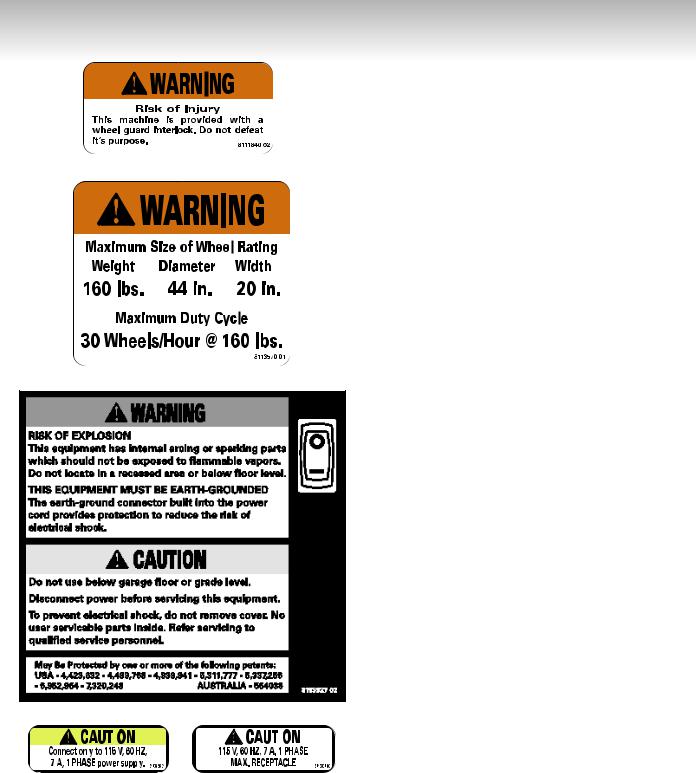
Safety Notices and Decals

 WARNING
Failure to follow danger, warning, and caution instructions may lead to serious personal injury or death to operator or bystander or damage to property. Do not operate this machine until you read and understand all the dangers, warnings and cautions in this manual. For additional copies of either, or further information, contact:
Hennessy Industries, Inc.
1601 J.P. Hennessy Drive
LaVergne, TN 37086-3565
(615)641-7533 or (800) 688-6359 www.ammcoats.com
The Lateral Runout unit of this machine contains a Class IIIa laser with a maximum output less than 5mW at a wave length of 650-670 nm. Avoid Exposure -
Laser radiation is emitted from its aperture.

 CAUTION
Use of controls, adjustments or performance of procedures other than those specified herein may result in hazardous radiation exposure.
There are NO service procedures or adjustments which can be performed on the laser in this product.
In case of failure, the entire lateral runout unit (part no. 80180126) must be replaced.
|
|
|
|
|
|
|
|
|
|
|
|
|
|
|
|
|
|
|
|
|
|
|
|
|
|
|
|
|
|
|
|
|
|
|
|
|
|
|
|
|
|
|
|
|
|
|
|
|
|
|
|
|
|
|
|
|
|
|
|
|
|
|
|
|
|
|
|
|
|
|
|
|
|
|
|
|
|
|
|
|
|
|
|
|
|
|
|
|
|
|
|
|
|
|
|
|
|
|
|
|
|
|
|
|
|
|
|
|
|
|
|
|
|
|
|
|
|
|
|
|
|
|
|
|
|
|
|
|
|
|
|
|
|
|
|
|
|
|
|
|
|
|
|
|
|
|
|
|
|
|
|
|
|
|
|
|
|
|
|
|
|
|
|
|
|
|
|
|
|
|
|
|
|
|
|
|
|
|
|
|
|
|
|
|
|
|
|
|
|
|
|
|
|
|
|
|
|
|
|
|
|
|
|
|
|
|
|
|
|
|
|
|
|
|
|
|
|
|
|
|
|
|
|
|
|
|
|
|
|
|
|
|
|
|
|
|
|
|
|
|
|
|
|
|
|
|
|
|
|
|
|
|
|
|
|
|
|
|
|
|
|
|
|
|
|
|
|
|
|
|
|
|
|
|
|
|
|
|
|
|
|
|
|
|
|
|
|
|
|
|
|
|
|
|
|
|
|
|
|
|
|
|
|
|
|
|
|
|
|
|
|
|
|
|
|
|
|
|
|
|
|
|
|
|
|
|
|
|
|
|
|
|
|
|
|
|
|
|
|
|
|
|
|
|
|
|
|
|
|
|
|
|
|
|
|
|
|
|
|
|
|
|
|
|
|
|
|
|
|
|
|
|
|
|
|
|
|
|
|
|
|
|
|
|
|
|
|
|
|
|
|
|
|
|
|
|
|
|
|
|
|
|
|
|
|
|
|
|
|
|
|
|
|
|
|
|
|
|
|
|
|
|
|
|
|
|
|
|
|
|
|
|
|
|
|
|
|
|
|
|
|
|
|
|
|
|
|
|
|
|
|
|
|
|
|
|
|
|
|
|
|
|
|
|
|
|
|
|
|
|
|
|
|
|
iv • |
|
|
|
Important: Always read and follow the on-screen operating instructions. |
|
|||||||||||||
Safety
Standard Safety Devices
• Stop key for stopping the wheel under emergency conditions.
• A hood guard of high impact plastic that is designed to prevent the counterweights from flying out in any direction except towards the floor.
•A hood switch interlock system that prevents the machine from starting if the guard is not lowered and stops the wheel whenever the guard is raised.
|
|
|
|
|
|
|
|
|
|
|
|
|
|
|
|
|
|
|
|
|
|
|
|
|
|
|
|
|
|
|
|
|
|
|
|
|
|
|
|
Important: Always read and follow the on-screen operating instructions. |
• v |
||||||
Safety
NOTICE
Read entire manual before assembling, installing, operating, or servicing this equipment.
vi • |
Important: Always read and follow the on-screen operating instructions. |

Contents
Table of Contents
Important Safety Instructions . . . . . . . . . . . .ii
Owner’s Responsibility . . . . . . . . . . . . . . . . . . . . . .iii
Operator Protective Equipment . . . . . . . . . . . . . . . .iii
Definitions of Hazard Levels . . . . . . . . . . . . . . . . . .iii
Safety Notices and Decals . . . . . . . . . . . . . . . . .iv - v
Standard Safety Devices . . . . . . . . . . . . . . . . . . . . .v
Balancing Your First Tire . . . . . . . . . . . .2 - 3
Principle Operating Parts . . . . . . . . . . . . . .4 - 9
Power Switch . . . . . . . . . . . . . . . . . . . . . . . . . . . . . .6
Air Gauge Panel . . . . . . . . . . . . . . . . . . . . . . . . . . . .6
Positioning Pedal . . . . . . . . . . . . . . . . . . . . . . . . . . .6
Using the Offset Arm . . . . . . . . . . . . . . . . . . . . . . .7
Sensor Measuring Systems . . . . . . . . . . . . . . . . . . .8
Printer . . . . . . . . . . . . . . . . . . . . . . . . . . . . . . . . . . .9
Understanding the
Video Display Screens . . . . . . . . . . . . . .10 - 13
Monitor and Initial Screen Feature Reference . . . .11
Menu Screen Flowchart . . . . . . . . . . . . . . . . .12 - 13
Balancer Function
Set-up and Review . . . . . . . . . . . . . . . . .14 - 16
General Set-up . . . . . . . . . . . . . . . . . . . . . . . .14 - 15
Balancing Set-up . . . . . . . . . . . . . . . . . . . . . . . . .15
Special Functions . . . . . . . . . . . . . . . . . . . . . . . . . .15
Additional Functions . . . . . . . . . . . . . . . . . . . . . . . .16
Advanced Balancing Functions . . . . . . .16 - 19
Initial Screen Options . . . . . . . . . . . . . . . . . . .16 - 17
Dynamic Modes . . . . . . . . . . . . . . . . . . . . . . . . . . .17
Static Modes . . . . . . . . . . . . . . . . . . . . . . . . . . . . .18
Special Modes . . . . . . . . . . . . . . . . . . . . . . . . . . . .18
Additional Options . . . . . . . . . . . . . . . . . . . . . . . . .19
Matching . . . . . . . . . . . . . . . . . . . . . . . . .20 - 22
Automatic Runout Detection . . . . . . . . . . . . . . . . .20
Optimization (Match Balance) . . . . . . . . . . . . . . . .21
Runout (Runout Match) . . . . . . . . . . . . . . . . . . . . .22
Manually Setting Wheel
Dimensions (DIM) . . . . . . . . . . . . . . . . . . . . .23
Mounting Wheel on Spindle Shaft . . . .24 - 25
Standard Back Cone Mounting . . . . . . . . . . . . . . .24
Standard Front Cone Mounting . . . . . . . . . . . . . . .25
Alternate Mounting . . . . . . . . . . . . . . . . . . . . . . . .25
Machine Self-calibration and
Service Adjustments . . . . . . . . . . . . . . .26 - 29
Machine Self-calibration . . . . . . . . . . . . . . . . . . . . .26 Service Adjustments . . . . . . . . . . . . . . . . . . . . . . .27 Distance Arm Calibration . . . . . . . . . . . . . . . . . . . .27 Width Sonar Calibration (If equipped) . . . . . . .27 - 28 Diameter Arm Calibration (Plastic) . . . . . . . . . . . . .28 Diameter Arm Calibration (Metal) . . . . . . . . . . . . .29
Diagnostic Procedures . . . . . . . . . . . . . .29 - 34
After Balance Vibration Problems . . . . . . . . . |
. . . .29 |
Troubleshooting . . . . . . . . . . . . . . . . . . . . . . . |
30 - 33 |
Machine Self-Test “Green Screen” . . . . . . . . |
. . . .34 |
Maintenance Instructions . . . . . . . . . . . . . . .35
Monitor Screen Adjustment . . . . . . . . . . . . . . . . .35
Installation Instructions . . . . . . . . . . . . .36 - 37
Receiving . . . . . . . . . . . . . . . . . . . . . . . . . . . . . . . .36 Electrical Requirements . . . . . . . . . . . . . . . . . . . . .36 Setup . . . . . . . . . . . . . . . . . . . . . . . . . . . . . . . . . . .36 Air Supply Connection . . . . . . . . . . . . . . . . . . . . . .36 Connect to Power . . . . . . . . . . . . . . . . . . . . . . . . .36 Floor and Space Requirements . . . . . . . . . . . . . . .37
Specifications . . . . . . . . . . . . . . . . . . . . . . . . .38
Features . . . . . . . . . . . . . . . . . . . . . . . . . . . . .38
Required Accessories . . . . . . . . . . . . . . . . . .39
Optional Accessories . . . . . . . . . . . . . . . . . . .39
Glossary of Terms . . . . . . . . . . . . . . . . . . . . .41
1750/1800 Functional Check for
Calibration . . . . . . . . . . . . . . . . . . . .Back Cover
Important: Always read and follow the on-screen operating instructions. |
• 1 |
Video Balancer
Balancing Your First Tire
Important: Always read and follow the on-screen operating instructions.
1. Turn the machine OFF then ON (resets machine).
The initial screen is in dynamic mode using standard clip-on wheel weight locations and wheel dimensions.
2. Mount a tire/wheel on the balancer that will use standard clipon wheel weights.
Use the most appropriate mounting method.
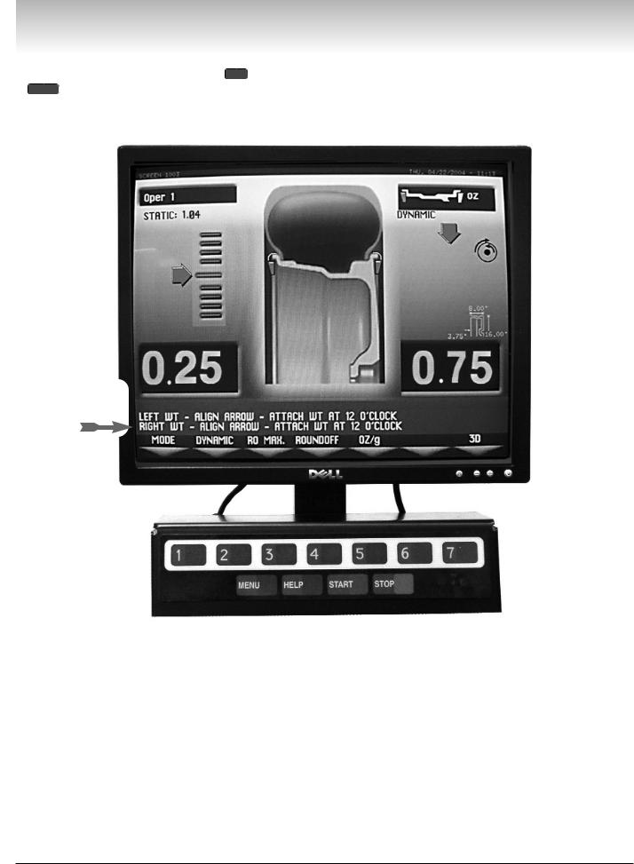
8. Rotate wheel to position left side placement arrow at the center bar.
As illustrated in figure 3, rotate the wheel to position the left side placement arrow at the center red bar. Step on the positioning pedal to hold the tire in place.
9. Attach left side corrective weight amount at top-dead center on the inside flange of the wheel.
Attach specified corrective weight amount (0.25 oz in figure 3) at top-dead-center on inside flange of wheel.
3. Always remove any weights already attached to the wheel.
Use the most appropriate mounting method. Always remove any weights attached to the wheel.
4. Enter A & D wheel dimensions using offset arm.
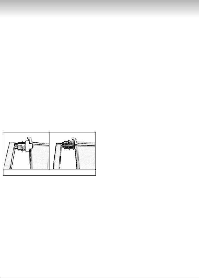
For Automatic Measurement — pull the offset arm out to the wheel, hold it still at clip-on weight position against the wheel flange, and wait for the BEEP.
10. Rotate wheel to position right side placement arrow at center bar.
Rotate the wheel to position the right side placement arrow at the center red bar. Step on the positioning pedal to hold the tire in place.
11. Attach the right side corrective weight.
Attach specified weight amount (0.75 oz in figure 3) at top-dead-center on the outside flange of the wheel.
12. Lower the hood to respin the tire/wheel and check balance.
Your weight readings should now be 0.00.
Note: Throughout this manual tire dimensions are referred to as A, W, and D, see figure 2.
Metal Offset Arm |
Plastic Offset Arm |
Figure 1 - Automatic Measurement
Clip-on Weight Location — viewed on a cut-away rim for clarification.
5. Enter Width wheel dimension.
Enter Width at DIM screen or, if equipped with the Hood Sensor System, lower the hood to automatically measure tire width.
6. The wheel spins and unbalances are measured and displayed.
The corrective weight amount appears on the video display screen for the left and the right planes of the wheel, see figure 3.
7. Raise hood after tire stops
Figure 2 - A, W, and D Tire Dimensions
rotating.
Note: If the hood is raised before the end of the spin, an error screen will appear. Wait for the weight amounts to display before raising the hood.
2 • |
Important: Always read and follow the on-screen operating instructions. |
Video Balancer
Note: To reset the mode back to the initial screen at any time, press the DYNAMIC option 2 or press the MENU key, or turn the machine OFF then ON. Note that if an operator is in a balance mode, it may be necessary to finish the balance cycle first.
Important: Always read and follow the on-screen operating instructions
Figure 3 - Weight Placement Screen Using Clip-on Weights
in Dynamic Mode
Important: Always read and follow the on-screen operating instructions. |
• 3 |
Video Balancer
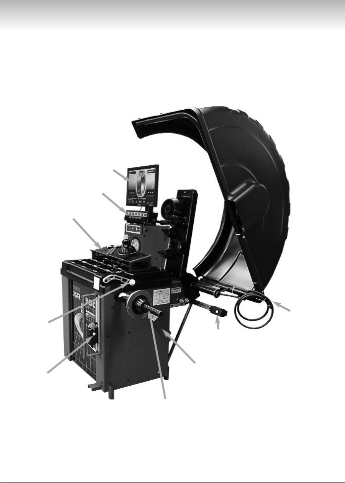
Principle Operating Parts
Monitor
Touch Panel
Portable Sliding
Storage Tray
ON/OFF and
Circuit Breaker (back of machine)
115 V UL Approved Plug (back of machine)
Offset Arm with |
|
|
|
|
|
|
|
|
||
|
|
|
|
|
|
Clip-on Air |
||||
Tape-A-Weight™ |
|
|
|
|
|
|
|
Chuck for |
||
Feature, |
|
|
|
|
|
|
|
Tire Inflation |
||
Measures A&D |
|
|
|
|
|
|
|
Adjustment |
||
|
|
|
Radial Runout |
|
||||||
of Tire/Wheel |
|
|
|
|
|
|
|
|
||
|
|
|
|
|
|
|
|
|||
|
|
|
|
Sensor (adjustable |
|
|
|
|||
(shown in home |
|
|
|
|
|
|
|
|
||
|
|
|
|
to center of tread) |
|
|
|
|||
position) |
|
|
|
|
|
|
|
|
||
|
|
|
|
|
|
|
|
|||
|
|
|
|
|
|
|
|
|
|
|
|
|
|
|
|
|
|
|
|
|
|
|
|
|
|
|
|
Sensor Target Bracket |
|
|
||
|
Lateral Runout |
|
|
|
(for calibration) |
|
|
|||
|
Sensor (adjustable |
|
|
|
|
|
|
|
|
|
|
|
|
|
|
|
|
||||
|
to sidewall of tire) |
|
|
|
|
|
|
|
|
|
|
|
|
|
|
|
|
|
|
|
|
|
|
|
|
|
|
|
|
|
|
|
|
|
|
|
40 MM Shaft |
|
|
||||
4 • |
Important: Always read and follow the on-screen operating instructions. |
Video Balancer
Tool Accessory
Storage
Tilting Monitor
Adjustment Knobs
Inflate Button 
Printer
Manual Tire
Bleed Valve
Adjustable
Air Gauge
Protected Side
Storage Pegs for
Accessories
Tire Width Sensor (measures when hood is lowered)
 Captured
Cone Spring
Weight Tray with Dual Pockets for Weights thru 2 oz. - Deep Pockets thru 4 oz.
Positioning Pedal -
Holds Position for
Weight Application
Important: Always read and follow the on-screen operating instructions. |
• 5 |
Video Balancer
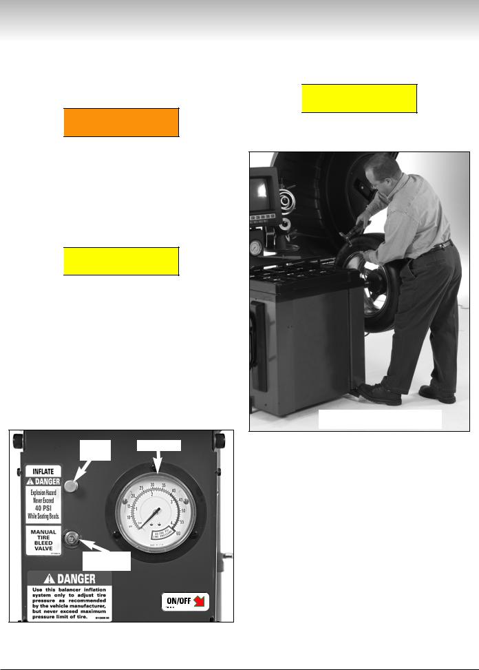
Power Switch
The ON/OFF decal, see figure 4, indicates the location of the ON/OFF switch at the back of the balancer. The circuit breaker reset button is also at this location.
Air Gauge Panel

 WARNING
NEVER exceed tire manufacturer’s recommended air pressure. Tires can explode, especially if inflated beyond these limits. Keep hands, arms, and entire body back from inflating tire. Avoid distraction during inflation. Check tire pressure frequently to avoid over inflation. Excessive pressure can cause tires to explode, causing serious injury or death to operator or bystander.

 CAUTION
Do not lower the hood with the clip-on air chuck attached to the tire’s valve stem.With the hood start feature ON, the tire will start rotation causing damage to the wheel and balancer and possible personal injury.
As shown, the wheel balancer is equipped with the capability to adjust the air pressure of the tire. The INFLATE push button supplies air through the hose and clip-on air chuck located at the wheel guard. When the chuck is attached to the valve stem, air pressure is indicated on the gauge. Excess pressure can be reduced using the MANUAL TIRE BLEED VALVE. See figure 4.
Inflate |
Air Gauge |
Button |
|
Positioning Pedal
Use the positioning pedal to hold the wheel position during weight application, as shown in figure 5.

 CAUTION
Do not actuate the positioning pedal during the measurement cycle. Do not use the positioning pedal as a brake.
Press Positioning Pedal with
Foot to Hold Wheel Position
Figure 5 - Positioning Pedal
Manual Tire
Bleed Valve
Figure 4 - Air Gauge Panel and ON/OFF switch decal that indicates ON/OFF switch location at the back of the balancer.
6 • |
Important: Always read and follow the on-screen operating instructions. |
Video Balancer
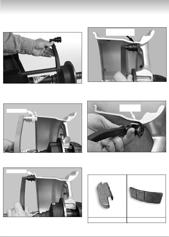
Using the Offset Arm
When prompted by the on-screen instructions, use the offset arm, see figure 6, to enter A & D measurements automatically.
To measure for a hidden weight location, place the offset arm at a hidden weight placement location as shown in figure 8.
Hidden Weight
Placement Location
Figure 6 - Offset Arm
To measure for a clip-on weight location, place the offset arm at the wheel flange as shown in figure 7A (metal arm) or figure 7B (plastic arm).
Wheel Flange
Figure 8 - Hidden Weight Location Viewed on a Cut-Away Rim for Clarification.
Use the offset arm Tape-A-Weight™ feature for accurate placement of hidden weights. See figure 9.
Location for
Hidden Weight
Figure 7A - Clip-on Weight Location Using Metal Offset Arm Viewed on a Cut-Away Rim for Clarification.
Wheel Flange
Figure 9 - Hidden Weight Placement Location Viewed on a Cut-Away Rim for Clarification.
Note: Throughout this manual wheel weights are referred to as Clip-on or Tape-A-Weight™ (Hidden Weight). Figure 10 shows an example of each weight.
Figure 7B - Clip-on Weight Location Using Plastic Offset Arm |
Clip-on Weight |
Tape-A-Weight™ |
Viewed on a Cut-Away Rim for Clarification.
Figure 10 - Corrective Weight Examples. For Best Results, use BADA® Brand Wheel Weights.
Important: Always read and follow the on-screen operating instructions. |
• 7 |
Video Balancer
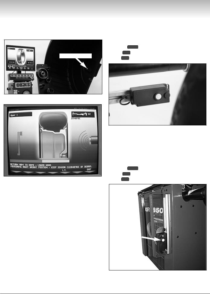
Sensor Measuring Systems
By lowering the hood, measure wheel width automatically using the Tire Width Sensor. See figures 10 and 11.
Tire Width Sensor
The sensor, shown in figure 12, is mounted on an adjustable slide at rear of machine and is used to measure radial runout of the tire when the eye of the sensor is centered on the tread width.
Important: To activate the radial runout function,
press the |
MENU button, select the GENERAL SET-UP |
|
option |
5 |
, and set the RUNOUT UNLOADED |
option |
7 |
to SONAR. |
Figure 10 - Tire Width Sensor
Figure 11 - Screen with Width Sensor Icon
Figure 12 - Radial Runout Sensor
The sensor, on especially equipped models, (shown in figure 13) is mounted on an adjustable slide and is used to measure lateral runout of the tire when the eye of the sensor is centered on the flat of the tire sidewall.
Important: To activate the lateral runout function,
press the |
MENU button, select the GENERAL SET-UP |
|
option |
5 |
, and set the RUNOUT UNLOADED |
option |
6 |
to SONAR. |
Lateral Runout
Sensor
Figure 13 - Lateral Runout Sensor
8 • |
Important: Always read and follow the on-screen operating instructions. |
Video Balancer
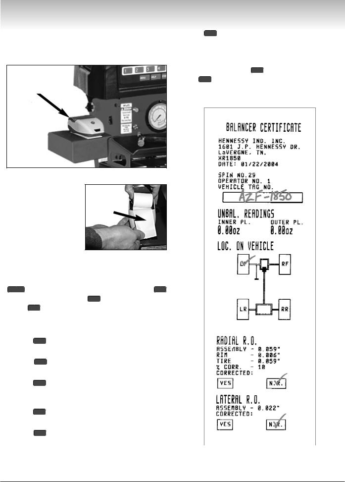
Printer
Use the printer, on especially equipped models, (shown in figure 14) to provide a BALANCER CERTIFICATE for the wheel balance service.
Printer
Option 7 CORRECTED - operator uses this area to manually check either YES if runout was corrected or N.R. if not required.
On selected screens, to print the BALANCER CER-
TIFICATE |
press option 6 . Note that the printout |
option 7 |
CORRECTED is only available for RUNOUT |
DIAGNOSTIC (see MATCHING on page 20 for more information).
Figure 14 - Printer
Important: The software will not recognize the printer unless there is paper in the printer. This is also the case if the paper is threaded between the paper roller and the printer top cover.
Install Roll of
Thermal Paper
The flashing LED on front of printer indicates power to the printer, but the printer could still be incorrectly connected or out of paper.
Important: To activate the printer function, press the
MENU button, select the GENERAL SET-UP option 5
select the PRINTER option 5 , and set the PRINTER |
|||
option 1 |
|
to ON. |
|
Also, toggle ON or OFF the following printer options |
|||
for the printout (default is ON for all these options): |
|||
Option |
2 |
OWNER ADDRESS - prints the owner’s |
|
address (see page 15 to customize to the machine). |
|||
Option |
3 |
SPIN NO. - records the spin no. from |
|
CYCLE HISTORY (see page 16 for more information). |
|||
Option |
4 |
OPERATOR NO. - indicates the operator |
|
number and name (see page 17 to customize to the |
|||
machine). |
|
|
|
Option |
5 |
VEHICLE TAG NO. - provides a space for |
|
the operator to write in the vehicle tag number. |
|||
Option |
6 |
LOC. ON VEHICLE - operator uses this |
|
diagram to manually check the wheel location that was |
|
||
serviced. |
|
Figure 15 - Completed Printer Balancer Certificate |
|
|
|
||
Important: Always read and follow the on-screen operating instructions. |
• 9 |
 Loading...