


775/875
See
Balancing Your
First Tire on page 1.
®
Wheel Balancer
Installation Instructions
Operating Instructions
Safety Instructions
Maintenance Instructions
READ these instructions before placing unit in service KEEP these and other materials delivered with the unit in a binder near the machine for ease of reference by supervisors and operators.
1601 J. P. Hennessy Drive, LaVergne, TN USA 37086-3565 615/641-7533 800/688-6359 www.ammcoats.com |
Manual Part No.: |
85008882 02 |
HENNESSY INDUSTRIES INC. Manufacturer of AMMCO®, COATS® and BADA® Automotive Service Equipment and Tools. |
Revision: |
03/08 |

ii • |
Important: Always read and follow the instructions. |

Table of Contents
Important Safety Instructions . . . . . . . . .iv - vi
Owner’s Responsibility . . . . . . . . . . . . . . . . . . . . . .v Operator Protective Equipment . . . . . . . . . . . . . . . .v Definitions of Hazard Levels . . . . . . . . . . . . . . . . . .v Safety Notices and Decals . . . . . . . . . . . . . . . . . . .vi Standard Safety Devices . . . . . . . . . . . . . . . . . . . . .vi
Balancing Your First Tire . . . . . . . . . . . . . . . .1
Principle Operating Parts . . . . . . . . . . . . . .2 - 3
Know Your Unit . . . . . . . . . . . . . . . . . . . . . . . . |
. . . .2 |
|
Power Switch . . . . . . . . . . . . . . . . . . . . . . . . . . |
. . . .3 |
|
Operating the Balancer . . . . . . . . . . . . . . |
4 - 11 |
|
Wheel Mounting . . . . . . . . . . . . . . . . . . . . . . . |
. . . .4 |
|
Standard Back Cone Mounting . . . . . . . . . . . . |
. . . .4 |
|
Standard Front Cone Mounting . . . . . . . . . . . . |
. . . .5 |
|
Control Panel And Display . . . . . . . . . . . . . . . . |
. . . .6 |
|
Operation Functions Menu . . . . . . . . . . . . . . . |
. . . .7 |
|
875 |
- Entering Wheel Dimensions . . . . . . . . . . |
. . . .8 |
875 |
- Automatic Dimension Presetting . . . . . . |
. . . .8 |
875 |
- Exact Positioning Of The Adhesive Weight |
|
By Means Of The Gauge With Clips . . . . . . . . |
. . . .9 |
|
775 |
- Manual Presetting Of Wheel |
|
Dimensions . . . . . . . . . . . . . . . . . . . . . . . . . . . |
. . .10 |
|
Result of Measurement . . . . . . . . . . . . . . . . . . |
. . .11 |
|
Recalculation Of The Unbalance . . . . . . . . . . . |
. . .11 |
|
Behind Spoke (Hidden Weight) . . . . . . . . . . .12
Match Mount . . . . . . . . . . . . . . . . . . . . . . . . .13
Correction Modes . . . . . . . . . . . . . . . . . . . . . .14
875 - Manual Dimension Presetting (Use
only in particular cases or for test) . . . . . . .15 Self-Calibration . . . . . . . . . . . . . . . . . . . . . . . .17 Display Saver . . . . . . . . . . . . . . . . . . . . . . . . .17 Maintenance Instructions . . . . . . . . . . . . . . .18 Diagnostic Procedures . . . . . . . . . . . . . . . . . .18
After Balance Vibration Problems . . . . . . . . . . . . . |
18 |
Installation Instructions . . . . . . . . . . . . . . . . .19
Receiving . . . . . . . . . . . . . . . . . . . . . . . . . . . . . . . .19 Standard Accessories . . . . . . . . . . . . . . . . . . . . . .19 Features . . . . . . . . . . . . . . . . . . . . . . . . . . . . . . . . .19 Specifications . . . . . . . . . . . . . . . . . . . . . . . . . . . . .19 Electrical Requirements . . . . . . . . . . . . . . . . . . . . .19 Floor and Space Requirements . . . . . . . . . . . . . . .20 Unpacking the Unit . . . . . . . . . . . . . . . . . . . . . . . .20 Remove Balancer from Pallet . . . . . . . . . . . . . . . .20 Connect to Power . . . . . . . . . . . . . . . . . . . . . . . . .20 Initial Testing . . . . . . . . . . . . . . . . . . . . . . . . . . . . .20 Hood Installation (Model 875) . . . . . . . . . . . . . . . .21
Important: Always read and follow the instructions. |
• iii |

IMPORTANT SAFETY INSTRUCTIONS
READ ALL INSTRUCTIONS
1.Eye and face protection recommendations:
“Protective eye and face equipment is required to be used where there is a reasonable probability of injury that can be prevented by the use of such equipment.” O.S.H.A. 1910.133(a) Protective goggles, safety glasses, or a face shield must be provided by the owner and worn by the operator of the equipment. Care should be taken to see that all eye and face safety precautions are followed by the operator. ALWAYS WEAR SAFETY GLASSES. Everyday glasses only have impact resistant lenses, they are not safety glasses.
2.Be sure that wheels are mounted properly, the hub nut engages the arbor for not less than four (4) turns, and the hub nut is firmly tightened before spinning the wheel.
3.Read and understand this manual before operating. Abuse and misuse will shorten the functional life.
4.Be sure the balancer is properly connected to the power supply and electrically grounded.
5.Do not operate equipment with a damaged cord or if the equipment has been dropped or damaged – until it has been examined and repaired by a qualified serviceman.
6.Do not let cord hang over edge of table, bench, or counter or come in contact with hot manifolds or moving fan blades.
7.If an extension cord is necessary, a cord with a current rating equal to or more than that of the equipment should be used. Cords rated for less current than the equipment may overheat. Care should be taken to arrange the cord so that it will not be tripped over or pulled.
8.Keep guards and safety features in place and in working order.
9.Wear proper clothing. Safety toe, non-slip footwear and protective hair covering to contain hair is recommended. Do not wear jewelry, loose clothing, neckties, or gloves when operating the balancer.
10.Keep work area clean and well lighted. Cluttered and/or dark areas invite accidents.
11.Avoid dangerous environments. Do not use power tools or electrical equipment in damp or wet locations, or expose them to rain.
12.Avoid unintentional starting. Be sure the balancer is turned off and power disconnected before servicing.
13.Disconnect the balancer before servicing.
14.Use only manufacturer’s recommended accessories. Improper accessories may result in personal injury or property damage.
15.Repair or replace any part that is damaged or worn and that may cause unsafe balancer operation. Do not operate damaged equipment until it has been examined by a qualified service technician.
16.Never overload or stand on the weight tray or any part of the balancer.
17.Do not allow untrained persons to operate machinery.
18.To reduce the risk of fire, do not operate equipment in the vicinity of open containers or flammable liquids (gasoline).
19.Adequate ventilation should be provided when working on or operating internal combustion engines.
20.Keep hair, loose clothing, fingers, and all parts of body away from moving parts.
21.Use equipment only as described in this manual.
22.Use only manufacturer’s recommended attachments and accessories.
SAVE THESE INSTRUCTIONS
iv • |
Important: Always read and follow the instructions. |
Owner’s Responsibility
To maintain machine and user safety, the responsibility of the owner is to read and follow these instructions:
•Follow all installation instructions.
•Make sure installation conforms to all applicable Local, State, and Federal Codes, Rules, and Regulations; such as State and Federal OSHA Regulations and Electrical Codes.
•Carefully check the unit for correct initial function.
•Read and follow the safety instructions. Keep them readily available for machine operators.
•Make certain all operators are properly trained, know how to safely and correctly operate the unit, and are properly supervised.
•Allow unit operation only with all parts in place and operating safely.
•Carefully inspect the unit on a regular basis and perform all maintenance as required.
•Service and maintain the unit only with authorized or approved replacement parts.
•Keep all instructions permanently with the unit and all decals/labels/notices on the unit clean and visible.
•Do not override safety features.
Operator Protective Equipment
Personal protective equipment helps make tire servicing safer. However, equipment does not take the place of safe operating practices. Always wear durable work clothing during tire service activity. Loose fitting clothing should be avoided. Tight fitting leather gloves are recommended to protect operator’s hands when handling worn tires and wheels. Sturdy leather work shoes with steel toes and oil resistant soles should be used by tire service personnel to help prevent injury in typical shop activities. Eye protection is essential during tire service activity. Safety glasses with side shields, goggles, or face shields are acceptable. Back belts provide support during lifting activities and are also helpful in providing operator protection. Consideration should also be given to the use of hearing protection if tire service activity is performed in an enclosed area, or if noise levels are high.
Definitions of Hazard Levels
Identify the hazard levels used in this manual with the following definitions and signal words:
DANGER
Watch for this symbol:

 DANGER
It Means: Immediate hazards, which will result in severe personal injury or death.
WARNING
Watch for this symbol:
 WARNING
It Means: Hazards or unsafe practices, which could result in severe personal injury or death.
CAUTION
Watch for this symbol:

 CAUTION
It Means: Hazards or unsafe practices, which may result in minor personal injury or product or property damage.
Watch for this symbol! It means BE ALERT! Your safety, or the safety of others, is involved!
Important: Always read and follow the instructions. |
• v |

Safety Notices and Decals

 WARNING
Failure to follow danger, warning, and caution instructions may lead to serious personal injury or death to operator or bystander or damage to property. Do not operate this machine until you read and understand all the dangers, warnings and cautions in this manual. For additional copies of either, or further information, contact:
Hennessy Industries, Inc. |
1601 J.P. Hennessy Drive |
LaVergne, TN 37086-3565 |
(615) 641-7533 or (800) 688-6359 |
www.ammcoats.com |
Model 775
Model 875
Standard Safety Devices
•Stop push button for stopping the wheel under emergency conditions.
•A hood guard of high impact plastic that is designed to prevent the counterweights from flying out in any direction except towards the floor.
NOTICE
Read entire manual before assembling, installing, operating, or servicing this equipment.
vi • |
Important: Always read and follow the instructions. |
Balancing Your First Tire
1. Turn the machine OFF then ON (resets machine).
Note: The machine wakes up using standard clip-on wheel weight locations (c1 & c2) and wheel dimensions.
2.Mount a tire/wheel on the balancer that will use standard clip-on wheel weights.
Use the most appropriate mounting method.
3.Always remove any weights already attached to the wheel.
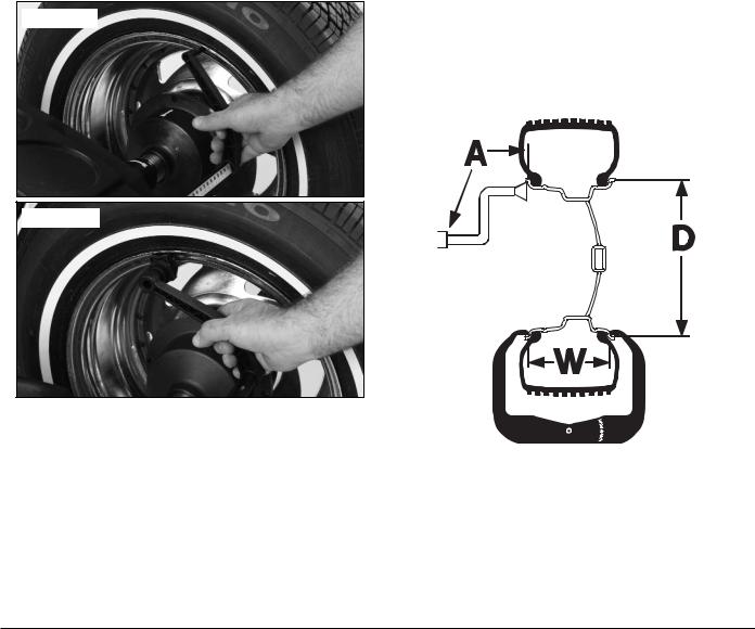
4.Enter A & D wheel dimensions
using offset arm.
Automatic Measurement — pull offset arm out to the wheel, hold it still at clip-on weight position against wheel flange. Return arm to home position.
Model 775
Model 875
Offset Arm At Clip-On Weight Location
5. Enter Width wheel dimension.
Use plastic calipers to measure wheel width. Use keypad to enter Width value.
6.Lower the hood, press Start; wheel spins and unbalances are
measured and displayed.
The corrective weight amount appears in the digital readout windows.
7. Raise hood after tire stops rotating.
Note: Wait for wheel to stop before raising the hood.
8.Rotate wheel to inboard (left plane) position of unbalance.
9.Attach inboard (left plane)
corrective weight.
Attach specified weight amount at top-dead-cen- ter on inside flange of wheel.
10.Rotate wheel to outboard (right plane) position of unbalance.
11.Attach outboard (right plane)
corrective weight.
Attach specified weight amount at top-dead-cen- ter on outside flange of wheel.
12.Lower the hood to respin the tire/wheel and check balance.
Your weight readings should now be 0.00.
Note: Throughout this manual tire dimensions are referred to as A, W, and D, see figure 2.
A, W, and D Tire Dimensions
Important: Always read and follow the instructions. |
• 1 |
Principle Operating Parts |
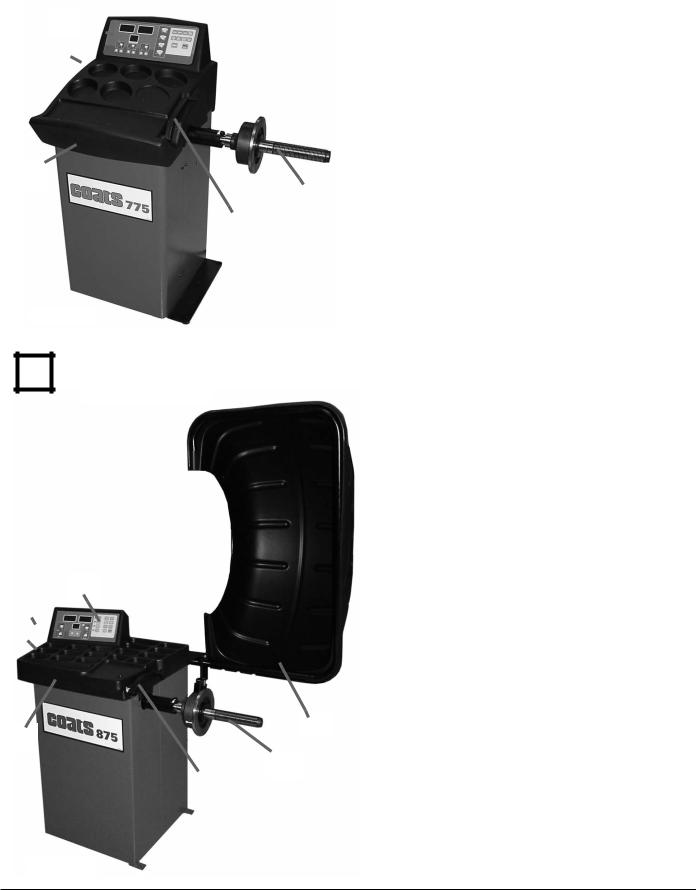
Know Your Unit |


Compare this illustration with the unit before placing it into service. Maximum performance and safety will be obtained only when all persons using the unit are fully trained in its parts and operation. Each user should learn the function and location, of all controls.
Prevent accidents and injuries by ensuring the unit is properly installed, operated and maintained.

Model 775
|
|
Model 775 |
|
|
|
Control Panel or Video Display Panel |
|
|
|
Plug (back of machine) |
|
|
|
||
|
|
ON/OFF |
|
|
|||
Weight Tray with Pockets for Corrective |
|||
|
|
||
|
|
Weights |
|
|
|
Offset Arm, Measures A & D of Tire/Wheel |
|
|
|
(shown in home position) |
|
|
|
40mm Shaft |
|
Do It Now!
Now is a good time
to fill out the Owner’s
Registry Card.


Model 875
Control Panel or Video Display Panel
Plug (back of machine)
ON/OFF
Weight Tray with Pockets for Corrective Weights
Offset Arm, Measures A & D of Tire/Wheel (shown in home position)
40mm Shaft
Hood Guard

Model 875
2 • |
Important: Always read and follow the instructions. |
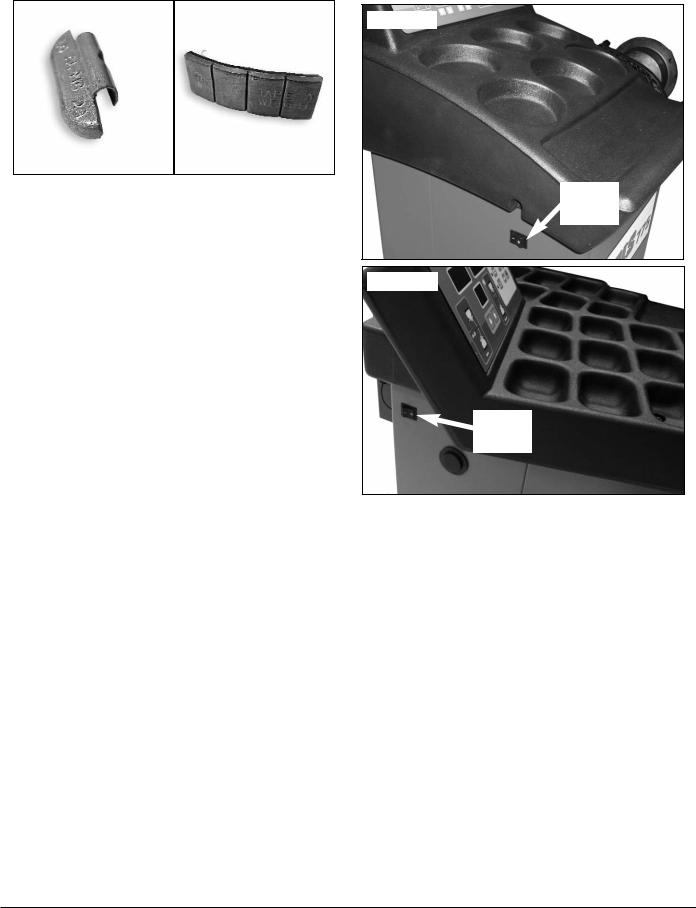
Note: Throughout this manual wheel weights are referred to as Clip-on or Tape-A-Weight™. Figure 3 shows an example of each weight.
Clip-on Weight |
Tape-A-Weight™ |
|
|
Corrective Weight Examples: For Best Results, use BADA® Brand Wheel Weights.
Power Switch
The ON/OFF switch location is on the side of the balancer; below the weight tray.
Model 775
ON/OFF
Power
Switch
Model 875
ON/OFF
Power
Switch
On/Off Switch
Important: Always read and follow the instructions. |
• 3 |
 Loading...