


Electro-Hydraulic Tire Changer
For Medium and Large Size Tires
CHD-6330
 OPERATING AND MAINTENANCE INSTRUCTIONS
READ these instructions before placing unit in service KEEP these and other materials delivered with the unit in a binder near the machine for ease of reference by supervisors and operators.
85010074/00 Revision 06/08

|
|
INDEX |
1 |
- GENERAL INFORMATION............................................................................................................................................... |
3 |
2 |
- TECHNICAL DATA........................................................................................................................................................... |
3 |
3 |
- GENERAL SAFETY REGULATION..................................................................................................................................... |
3 |
4 |
- SAFETY DEVICES............................................................................................................................................................. |
3 |
5 |
- TRANSPORT..................................................................................................................................................................... |
4 |
6 |
- UNPACKING................................................................................................................................................................... |
4 |
7 |
- INSTALLATION ................................................................................................................................................................ |
4 |
|
7.1 Installation place............................................................................................................................................................................... |
4 |
|
7.2 Workplace requirements.................................................................................................................................................................. |
5 |
|
7.3 Electric hook up................................................................................................................................................................................. |
6 |
|
Sense of rotation check |
|
8 |
- LAYOUT OF FUNCTIONAL PARTS................................................................................................................................... |
7 |
9 |
- IDENTIFYING WARNING SIGNALS................................................................................................................................. |
8 |
10 - IDENTIFICATION OF CONTROL.................................................................................................................................... |
9 |
|
11WORKING POSITION..................................................................................................................................................... |
9 |
|
12 - CORRECT OPERATION CHECKS.................................................................................................................................. |
9 |
|
13 - OPERATION................................................................................................................................................................. |
11 |
|
13.1 Rim clamping...................................................................................................................................................................................... |
11 |
|
|
Light-alloy rim clamping |
|
13.2 Tubeless and supersingle tires........................................................................................................................................................... |
12 |
|
|
Bead losening |
|
|
Demounting |
|
|
Mounting |
|
13.3 Tubed tires........................................................................................................................................................................................... |
17 |
|
|
Bead losening |
|
|
Demounting |
|
|
Mounting |
|
13.4 Tire assembly with split ring............................................................................................................................................................................... |
20 |
|
|
Bead losening and demounting |
|
|
Mounting |
|
14 - ORDINARY MAINTENANCE....................................................................................................................................... |
24 |
|
15 - TROUBLE SHOOTING.................................................................................................................................................. |
25 |
|
16MOVING THE MACHINE............................................................................................................................................. |
25 |
|
17STORING...................................................................................................................................................................... |
25 |
|
18SCRAPPING A MACHINE............................................................................................................................................ |
26 |
|
19DATA ON SERIAL PLATE............................................................................................................................................... |
26 |
|
20ACCESSORIES.............................................................................................................................................................. |
27 |
|

1 
 GENERAL INFORMATION
This tire changer has been specifically designed to fit and remove truck, bus and commercial agriculture and Off road tires, with rims from 13" to 27" and a maximum 63” (2,300 mm) diameter.
Any other use is improper and therefore not authorized. Before beginning any kind of work on or with this machine, carefully read and understand the contents of these operating instructions.
The Manufacturer shall not be liable for any injury to persons or damage to things caused by improper use of this machine.
KEEP THIS MANUAL NEAR THE MACHINE AND CONSULT IT AS NEEDED DURING OPERATIONS.
2 |
|
TECHNICAL DATA |
|
|
|
Electric Power requirement
Pump motor
Gear-box motor
Handles rim from
Max. wheel diameter
Max. wheel width
Max. wheel weight
Weight (with standard accessories)
Acoustic pressure level (at work)

 220V - 3 PH - 60Hz 15 Amp
2.0 HP (1.5 kw)
1.7-2.4 HP (1.3 / 1.8 kw)
14" - 56"
90” (2,300 mm)
42” (1,065 mm)
3,300 lbs (1,500 kg)
1,698 lbs (770 Kg)
LpA <70 dB (A)
3 |
|
GENERAL SAFETY REGULATIONS |
The use of this machine is reserved to specially trained and authorized personnel.
Any unauthorized changes or modifications to the machine, in particular to its electric system, relieve the manifacturer from all liability and warranty claims.
Removing or tampering with the safety devices installed on this machine is a violation of International Safety Regulations, and, as such, once again relieves the manufacturer from all liability and warranty claims.
Any work, however minor, on the electric system must be done exclusively by professionally qualified electrician.
4 |
|
SAFETY DEVICES |
|
|
|
The tire changer has a number of safety devices designed to guarantee the utmost operator safety:
1.Check valve on the spindle opening hydraulic line (inside the swivel connector, see fig. B/1). This prevents the tire assembly off falling from the spindle if the hydraulic line is accidentally broken.
2.Pressure relief valve factory set at 1,885 PSI (130 bar) ±10% (See Fig. B/2).
This limits the pressure in the hydraulic circuit and ensure correct operation of the plant.
3.Pump motor overload shut-off (inside the electric enclosure). This provides automatic shut-off for the motor to prevent damage from overheating.
4.Check valve on the chuck arm lifting hydraulic line. This prevents the chuckarm from descendingwhen any accidental break occurs in the hydraulic circuit.

B/1 |
B/2 |
5 TRANSPORT
The machine is delivered in a wooden crate with pallet
The machine must be handled with a fork-lift truck with forks positioned as shown in figure A/2.
Shipping weight for the machine is 1,390 lbs (630 kg).
1,390 lbs (KG. 630)
A/2
6 UNPACKING
Once the packing material has been removed, check the machine visually for any signs of damage. Keep the packing materials out of the reach of children as they can be a source of danger.
Keep the packing for possible future transport.
7 INSTALLATION
7.1 INSTALLATION PLACE
Choosetheplacethemachineistobeinstalledincompliancewithcurrentworkplacesafetyregulations.Thefloorshouldnotbebroken or uneven so that the machine will be stable and the platform rollers can move freely.
If the installation is outdoor, it must be protected by some kind of roofing against rain. The following work environment conditions are applicable:
Relative humidity: from 30-95% without condensation; Temperature: from 32°-131° F (0-55° C).
ATTENTION!
The machine must not be operated in explosive atmospheres.
7.2 |
|
WORK PLACE REQUIREMENT |
|
|
|
Maximum machine space requirements are 88.2X6.3 inches (2,240x 1,640 mm) with a minimum distance from walls as shown in the diagram.
CAUTION! These measurements are also the tire changers working range. Persons other than specially trained and authorized operators are expressly forbidden to enter this area.
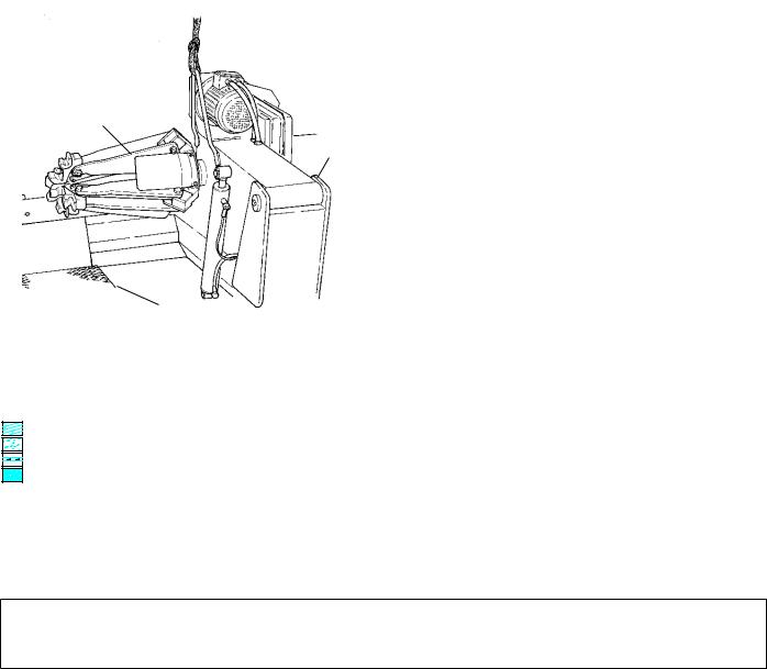
Position the tire changer lifting it with the specific bracket (1, Fig. A) with the tool carrier arm (2, Fig. A) lowered all the way, the spindle (3, Fig. A) closed and the tool carrier slide (4, Fig. A) at its stop close to the arm.
The mobile control unit has no fixed position, but it must be
positioned in a way that the user can observe the machine when working
3 |
1 |
|
|
|
inches |
mm) |
|
98.4inches (2,500mm) |
|
|
|
|
|
|
|
|
|
|
|
||||||
|
|
|
|
|
|
|
|
|
|
|
||
|
|
|
|
|
|
|
|
|
|
|
|
|
|
2 |
|
27.5 |
(700 |
|
|
|
|
|
|||
|
|
|
|
|
|
|
|
|
|
|||
|
|
|
|
|
|
|
|
|
|
|
98.4 inches |
|
|
|
|
|
|
|
|
|
|
|
|
||
|
|
|
|
|
|
|
|
|
|
|
(2,500 mm) |
|
|
|
|
|
|
|
|
|
|
39.3 inches |
|
|
|
|
|
|
|
|
|
|
|
|
|
|
||
|
|
|
|
|
|
|
|
|
|
|
||
|
4 |
|
|
|
|
|
|
|
(1,000 mm) |
B/5 |
||
|
|
|
|
|
|
|
|
|
|
|
|
|
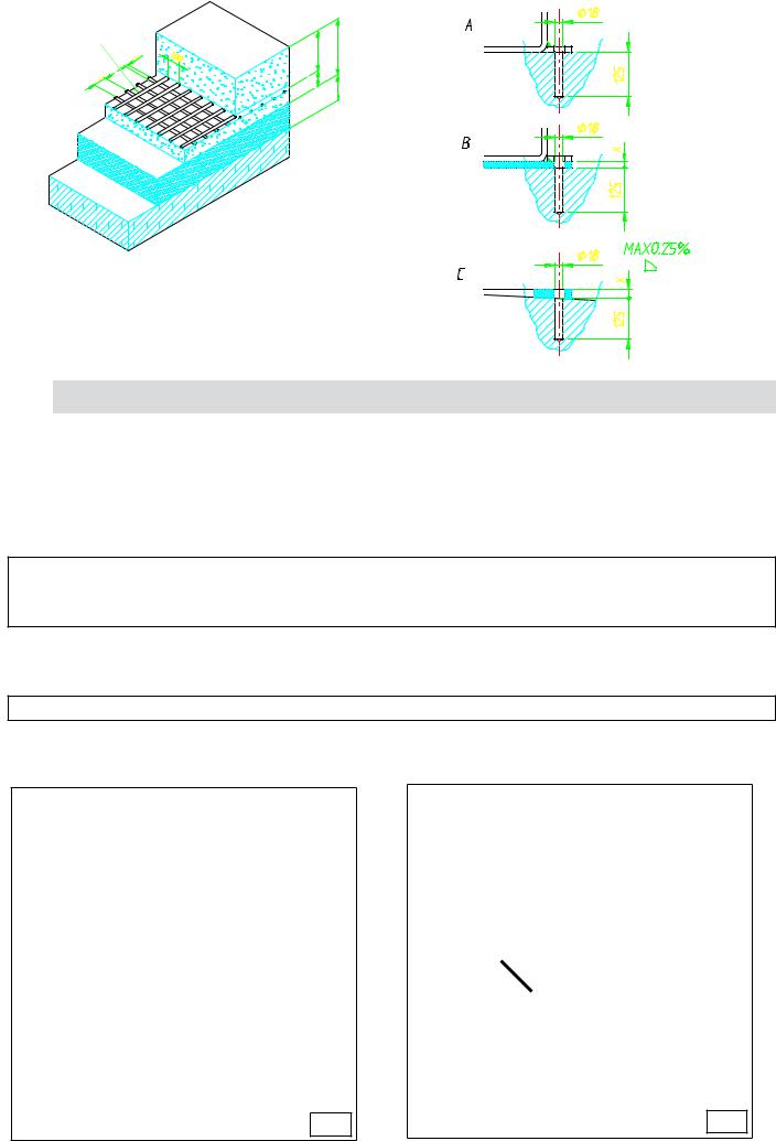
The tire-changer must be installed on a levelled concrete floor at least 8” (20 cm) . thick, with a minimum concrete quality of B25 in accordance with DIN 1,045 requirements (foundations).
For your reference see the side drawing as well as the table herebelow.
|
Foundationsdimensions inch (cm). |
Concrete |
Min. pressure |
|||
Ground |
quality |
resistence |
||||
|
|
|
||||
|
|
|
|
|
||
Reinforced concrete |
|
|
|
|
|
|
Length |
Width |
Thickness |
|
|
||
Electrowelded grid |
|
|
||||
|
|
|
|
937 lbs/sqft |
||
Pebble gravel |
|
|
|
B25 |
||
78,74 |
64,5 |
5,9 |
(425 Kg / cm2) |
|||
|
||||||
|
(200) |
(164) |
(15) |
|
|
|
|
|
|
|
|
|
|
If a floor of this type is not available on site, fastening points of the specified concrete quality are acceptable.
The surface, on which the universal tire-changer is to be installed, must be flat and well levelled in all directions.
Inclinations up to 0,25% relative to the horizontal can be compensated using suitable shims, wedges or alike.
When working with wheels, whose weight is higher than 2,204 lbs (1,000 kg)., it is necessary to fasten the tire-changer to the floor by means of proper anchor bolts.
By means of a Widia bit Ø 16 drill a 0.630 inch hole (130 mm) into the floor passing through the holes provided on the base frame.
If there is an additional floor covering (B), or if shims or wedges are necessary for levelling (C), longer anchor bolts must be used.
Place an anchor bolt into each hole.
Make sure the anchor bolts extend at least 4.90” (125 mm). into the concrete slab, as indicated in the drawing.
Tighten the anchor bolts completely.
0,31 øinches
3,93 inches
|
|
Ø 0,7 |
3,93 |
5,90 |
|
1,96 |
3,93 |
4,9 |
Ø 0,7 |
4,9 |
MAX 0,25% |
Ø 0,7 |
4,9 |
7.3 |
|
ELECTRIC HOOK UP |
Before making any electric hook up, check to be certain that the main voltage corresponds to that stamped on the voltage tag (attached to the cord near the tire changer’s plug).
It is absolutely essential that :
-The system is equipped with a good grounding circuit.
-The current intake is adeguately protected against overcurrents with fuses or automatic magneto-thermic switch
Note the required power draw as highlighted on the data plate fixed to the tire changer. Check to make sure the shop electric wiring circuit is dimensioned sufficiently to carry this.
Work on the electric system, even if minor, must be done exclusively by professionally qualified electrician.
Manufacturer shall not be liable for any injury to persons or damage to things caused by failure to comply with these regulations and can cancel warranty coverage.
SENSE OF ROTATION CHECKS
Connect the machine to the mains, switch “ON” (5, fig. B/7) and check that the gearbox motor rotation corresponds to the indicating arrow (6, fig. B/6).
If not, switch two wires in the plug .
|
|
|
12 |
6 |
|
|
|
|
|||
|
|
|
|
|
5 |
|
|
B/6 |
B/7 |

8 LAYOUT OF FUNCTIONAL PARTS
1 - Lifting bracket
2 - Self-centering chuck holding arm
3 - Self-centering chuck
4 - Sliding ramp
8 - Handler
9 - Switch
10 - Pedal
13 - Carriage
14 - Tool holding arm
15 - Arm lever
17 - Bead losening disk
18 - Tool
19 - Pedal
22 - Jaw
C
WARNING!
During all operations, keep hands and other parts of the body as far as possible from moving parts of the machine. Necklaces, bracelets and too large clothes, can be dangerous for the operator.
22 |
3 |
1 |
2 |
|
|
|
|||
|
|
|
|
|
A
18 |
|
|
17 |
|
|
14 |
15 |
|
13 |
||
|
||
|
19 |
|
|
D |

9 
 IDENTIFYING WARNING SIGNALS
WARNING:
Unreadable and missing warning labels must be replaced immediately.
Do not use the tire changer if one or more labels are missing.
Do not add any object that could prevent the operator from seeing the labels.
Use ref. code # 2019113 to order labels set, if needed
|
|
3005087 |
|
3005421 |
3006038 |
3005423 |
3006037 |
|
|
|
3000962
3005419
3000964
3005410
3000965
3008615
3008614
3000961
3000963
3013614
3008616
3005417
10 |
|
IDENTIFYING CONTROLS |
|
|
|
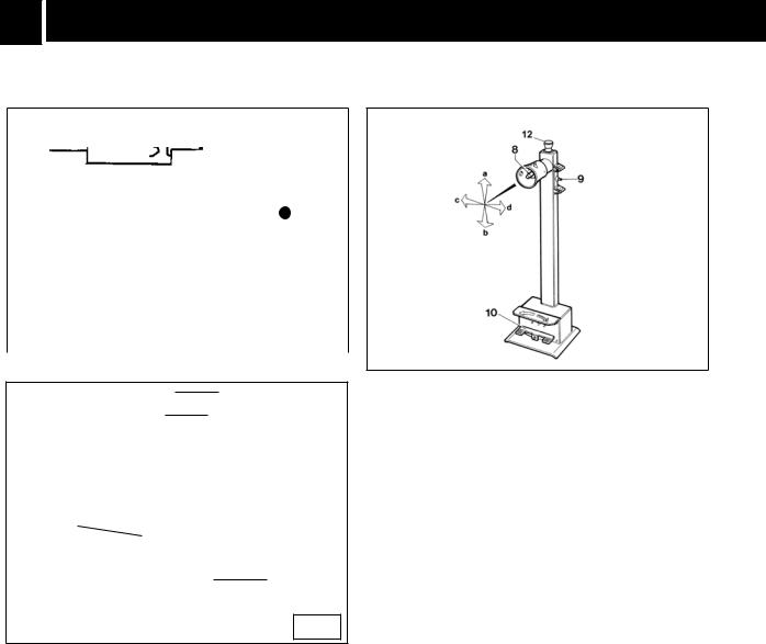
The mobile control unit (fig. C) enables the operator to work at any position around the machine. On this mobile control unit the following controls are located:
-The lever (8, fig. C) which in position [a] lifts the chuck arm and in position [b] lowers it; in position [c] moves the tool holder arm and the sliding table towards the self-centering chuck and in position [d] moves them away.
Note: in order to memorise this operation, there is a hole in the lever guard corresponding to position c.
-The chuck switch (9, fig. C) when moved upwards, opens the arms of the self-centering chuck (LOCKING), and when moved down, closes the arm of the self-centering chuck (UNLOCKING).
-The pedal (10, fig. C) when pressed on the left or right side rotates the self-centering chuck in the same direction as shown by the arrows placed on the foot pedal.
Both rotations can be made with two different speeds, just placing the selector (12, fig. B/6) in position 1 for getting slow rotation and in position 2 for fast rotation of the turntable
The tire changer also has:
Handle (19, Fig. D) to tip the tool carrier arm (14, Fig. 4) from its work to its non-working position and vice-versa.
Handle (15, Fig. D) for alternative use of the bead-losening disk (17, Fig. D) or the hooked tool (18, Fig. D). Pressing the emergency stop button (12, fig C) will stop any operation in course
11 |
|
WORKING POSITION |
|
|
|
The diagram B/8 illustrates the various working positions (A,B,C,D) referred to in the following pages describing how to use the tire changer. Use of these positions ensures greater precision, speed and safety for those using the machine.
12 
 CORRECT OPERATION CHECKS
Before using the tire changer, a number of checks should be made to ensure it works correctly.
CAUTION! The operations described here should be done with the tool carrier arm in its non-working position.
 a
a
b
d |
c |
|
|
|
|
|
B/8 |
|
|
|
|
|
|
|
C |
||
|
|
|
|
|
|
|
|
|
|
18
17
14
 15
15
13
19
D
 Loading...