


Truck Wheel Balancer
Model 6200HS
OPERATION GUIDE
FORM 8184342

Operation Guide
CONTENTS |
|
Safety Cautions and Warnings ......................... |
ii |
Installation ....................................................... |
iii |
Unpacking ......................................................... |
iii |
Assembly .......................................................... |
iii |
Setup ................................................................ |
iv |
Weight Increment Selection Mode .................... |
iv |
12V Battery Operation ...................................... |
iv |
Introduction ...................................................... |
1 |
Features .......................................................... |
2 |
Accessories ..................................................... |
3 |
Standard Adaptors ............................................ |
3 |
Functional Description ..................................... |
4 |
Balancer Display ............................................... |
5 |
Input Panel ........................................................ |
6 |
Offset Scale ...................................................... |
7 |
Callipers ............................................................ |
8 |
Accessory Storage ............................................ |
8 |
Crank Handle .................................................... |
8 |
Weight Storage ................................................. |
8 |
Balancing Operation ........................................ |
9 |
Operating Procedure ........................................ |
9 |
Balancing Errors ............................................. |
12 |
Weight Modes................................................ |
13 |
Normal (clip-on) .............................................. |
13 |
Alu/Mag ........................................................... |
13 |
Static ............................................................... |
14 |
Weight Location Dimensions .......................... |
14 |
Special Applications ...................................... |
15 |
Wheel Mounting Methods .............................. |
17 |
Wheel Mounting Methods (Truck) .................. |
17 |
Wheel Mounting Methods (Automobile) ......... |
19 |
Power Sources .............................................. |
23 |
Automatic Calibration..................................... |
24 |
Calibration Procedure ..................................... |
24 |
Calibration Errors ............................................ |
25 |
Service and Maintenance .............................. |
26 |
Operational Check .......................................... |
26 |
Troubleshooting Guide .................................. |
28 |
Technical Specifications ................................ |
30 |
i

Coats Model 6200HS
SAFETY CAUTIONS AND WARNINGS
1.Read the Operators Manual before operating the balancer for the first time. Follow all instructions and warnings marked on the product.
2.The balancer operates from a) 110Vac, 60 Hz wall outlet with the supplied 8.5Vac power converter b) 12Vdc supply. Do not use any other electrical sources. Use only an EARTHED electrical power source. Use only a correctly rated replacement fuse.
3.Arrange the power cord so that it will not be tripped over or pulled, and keep it clear of moving parts. If an extension cord is used, ensure its current rating equals that of the power cord supplied. Immediately replace a damaged power cord.
4.Ensure the balancer rests on all three feet on a clean, level floor with no debris under the base.
5.Do not operate the balancer: a) near fumes or exposed flammable liquids; b) on wet surfaces. Do not expose the balancer to rain.
6.Adopt the correct lifting procedures when lifting any object. Weights in excess of 100lb (45kg) should not be lifted unaided.
7.NEVER remove a cover or access panel on the balancer without first disconnecting the balancer from the electrical power source.
8.Only authorized and trained operators should use the machine.
9.Wear approved eye protection when removing or attaching weights. Keep hair, clothing and all parts of the body clear of balancer moving parts.
10.Remove all stones, old weights, and other debris from the wheel before balancing.
11.Centre and tighten the wheel on the shaft before spinning the wheel.
12.Check that all wheel weights are properly applied and secured.
13.The balancer will return to the normal power-up state if the power is interrupted.
14.When the balancer is not in use, disconnect the power cord and use the available pegs and trays for storage of accessories.
ii
INSTALLATION
Your Model 6200HSTruck Balancer and accessories will be delivered in a single carton mounted on a pallet.
Unpacking
A.Unpack the balancer and all accessories.
B.Check the contents list below and confirm that all parts are present. Check also for the standard wheel mounting accessories and any optional accessories you may have ordered.
Qty Item
1Balancer assembly.
1Stub shaft and bolt.
1Plug-in power converter.
1Light truck cone.
1Medium truck cone.
1Large truck cone.
1Rim width Callipers.
1Spacer Ring.
1Hub nut assembly.
1Operators manual.
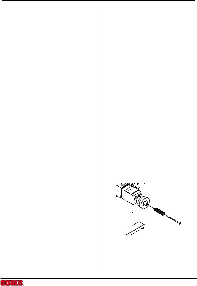
Assembly
Tools required : 10mm and ½” spanner Philips screwdriver 9/16 thin wall socket
1.Place the balancer on a firm solid floor.
2.Fix the stub shaft to the spindle, by inserting the bolt and 2 washers then tightening to a torque of 30Nm (110Ibsin -130Ibsin) using a 9/16 thin wall socket.
3.Verify the correct voltage is shown on the product serial label and the power converter supplied. Plug the power converter into the mains outlet. Connect the power converter cord to the input connector at the rear of the balancer measuring head. The balancer beeps and is switched on.
Your balancer is now ready for use!
Operation Guide
iii
Coats Model 6200HS
Setup
The balancer is programmed before leaving the factory to display weight imbalance in grams.To change this setting to ounce units, press oz/gram button, a decimal point appears in the Display Window (0.00). Repeating these steps will change the units back to grams (000).
Weight Increment Selection Mode
Machine is shipped in 25g (1oz) Increments to switch to 50g (2oz) Increments, follow this procurdure.
1.With the machine powered off press and hold the mode button.
2.Turn the power back on while still holding down the mode button, wait about 7 seconds for the machine to beep, machine is now in 50g (2oz) increments.
Maintenance
1.Clean mounting accessories, mounting surface, and spindle of balancer regularly. Grease and oil accumulate dirt which can cause incorrect balance results, and also act as a grinding compound resulting in premature wear.
2.A light coating of grease should be maintained on the sliding contact faces of the lifting section.
3.Remove wheel weights and rubbish from under the balancer.
4.Do not lean any tyres, rims, tools or other parts against the balancer.
5.Clean the Control Panel and Display Window with window cleaner.
iv
INTRODUCTION
The Coats Truck Balancer combines advanced, highperformance technology, robustness, reliability and simplicity of operation.
The features of the Coats Truck Balancer cater for all wheel service facilities. It is designed for use under a wide range of conditions, and will maintain perfect operation under the most demanding usage.
Low-speed rotation of the wheel by hand-spinning ensures that the Coats Truck Balancer is one of the safest machines available.
The Coats Truck Balancer offers complete portability and features an easy-to-use Display and Input Panel, ensuring quick and intuitive operation. Operator time and effort are reduced to a minimum, while maintaining wheel balancing accuracy and repeatability.
Take a few minutes to study this manual and become acquainted with the features and capabilities of your new Coats Truck Balancer before operating the balancer for the first time.
Operation Guide
1
Coats Model 6200HS
FEATURES
The COATS computerized wheel balancer combines state-of-the-art electronic accuracy with ease of use and simplicity of design.Your COATS product will give you years of reliable operation and wheel balancing profits.
The Balancer represent today’s most advanced concepts in wheel balancing with these high-precision features:
Safe, accurate, low-speed operation -
Balance Truck wheels to 5 gram accuracy (Automobile wheels to 2 gram) at an operating speed of only 70 rpm.
Fast and simple -
With a single spin cycle of between 10 and 20 seconds (depending on wheel size) and a large display that shows the exact weight requirement and location, your balancer will promote productivity and profits.
Electronic simplicity -
All major components can be replaced in the field, and the automatic self calibration program allows the balancer to calibrate itself with little or no downtime.
Six balancing modes-
Normal for standard clip-on weights on the inner and outer rim flanges.
Static (single plane) for some specialty wheels.
Four Custom modes for combinations of clipon and stick-on weights, including hidden-weight balancing.
Lightweight and Portable -
The patented hand operated wheel lifting mechanism (no pneumatics) and built in battery, allow the balancer to be taken to the Truck. The battery automatically recharges when the unit is connected to the mains supply.
Economical -
The balancer conserves energy by powering down when not in use. Mounting a wheel automatically powers up the unit again.
2
Operation Guide
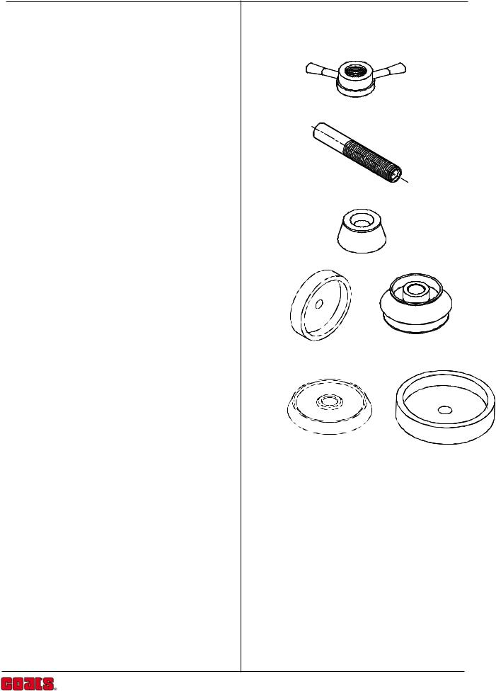
ACCESSORIES
Standard Adaptors
Standard Wing Nut |
(P/N 8112103) |
40 x 4 Shaft
Cone ( 3.25"-5.25") (P/N8112101)
Lt Truck Cone Kit (cone and backplate) (P/N 8113277C)
Hub Centered Truck Cone Kit (cone and backplate) (P/N 8111853C)
Not shown:
Rim Width Caliper (P/N 8309011)
Not shown:
AC Power Convertor 120V (P/N 6605-000101)
3

Coats Model 6200HS
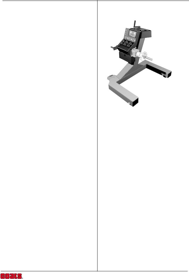
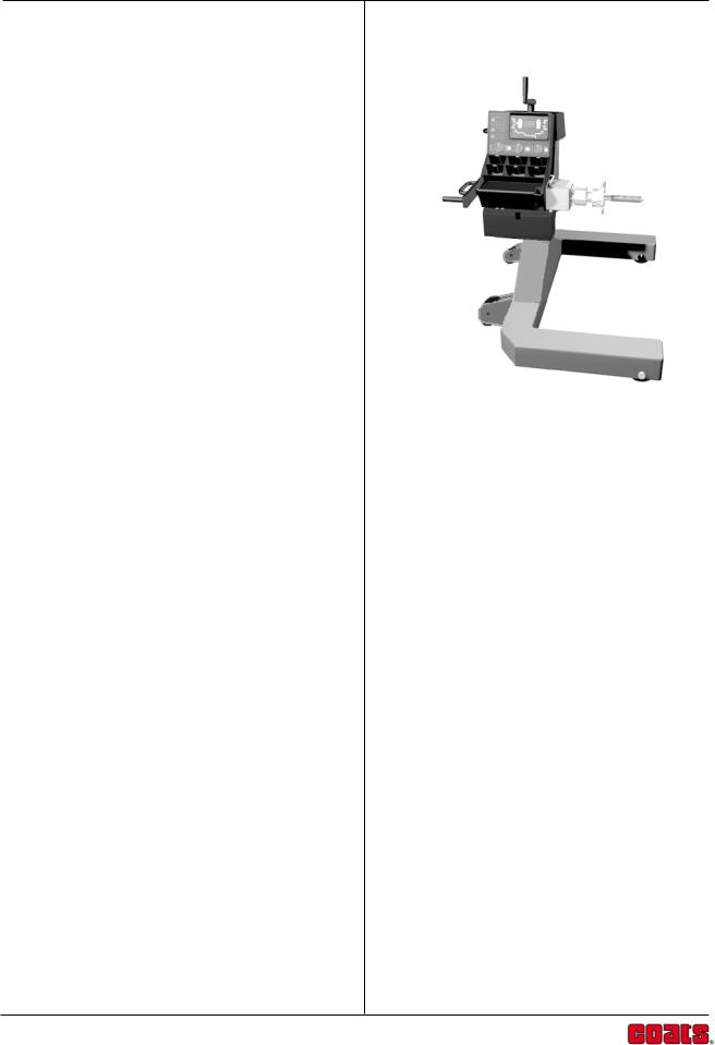
FUNCTIONAL DESCRIPTION
The following diagram shows a view from the front of the complete assembledTruck Wheel Balancer.
1 |
10 |
2 |
4 |
5 |
8 |
1.Input Panel
2.Display Panel
3.Weights Storage
4.Offset Scale
5.Stub Shaft
6. Flange |
9 |
7 |
3 |
6 |
7.Hammer Holster
8.Accessory Storage
9.Crank Handle
10.Lift Handle
4
Operation Guide
Balancer Display
The display combines solid-state electronics and graphical design to provide powerful visual presentation and durability.
The display indicates the amount and position of weights, wheel dimensions, operating modes and error conditions.
1. Numeric Display
Displays weights in grams or ounces after a spin cycle, when the wheel is rotated to the inner or outer Top- Dead-Center position. Displays wheel dimensions (diameter, width, offset) in inches or millimeters during wheel data entry. Displays ‘EEE’ to report an error.
2. Decimal Point
Illuminated constantly when ounces are selected as weight units.
3. Weight Position Indicators
Illuminated sequentially as the wheel is rotated and the correct position for weight placement is approached. This applies to both inner (3a) and outer (3b) weight positions.
4. Top-Dead-Center Indicators
Illuminated when the correct position for attaching the weight atTop-Dead-Center (TDC) is reached.There are separate indicators for the inner (4a) and outer (4b) TDC positions.
5. Rim Profile
Graphical rim profile to illustrate the Weight Mode in operation.
6. Weight Mode Indicators
Illuminated Clip-On Weight (green, circular) and StickOn Weight (yellow, rectangular) indicators to correspond to the Weight Mode selected.
7. Car Indicator
When the rim diameter is set at 17" or less the Car Indicator will light. This allows wheels to be Fine balanced to an accuracy of 2 grams (0.10 ounce). Refer also to the Weight Location Modes and Automatic Calibration sections of this manual for further details.
3a |
4a |
2 |
1 |
4b |
3b |
7 6 |
5 |
6 |
5
Coats Model 6200HS
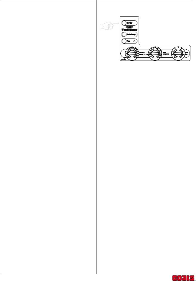
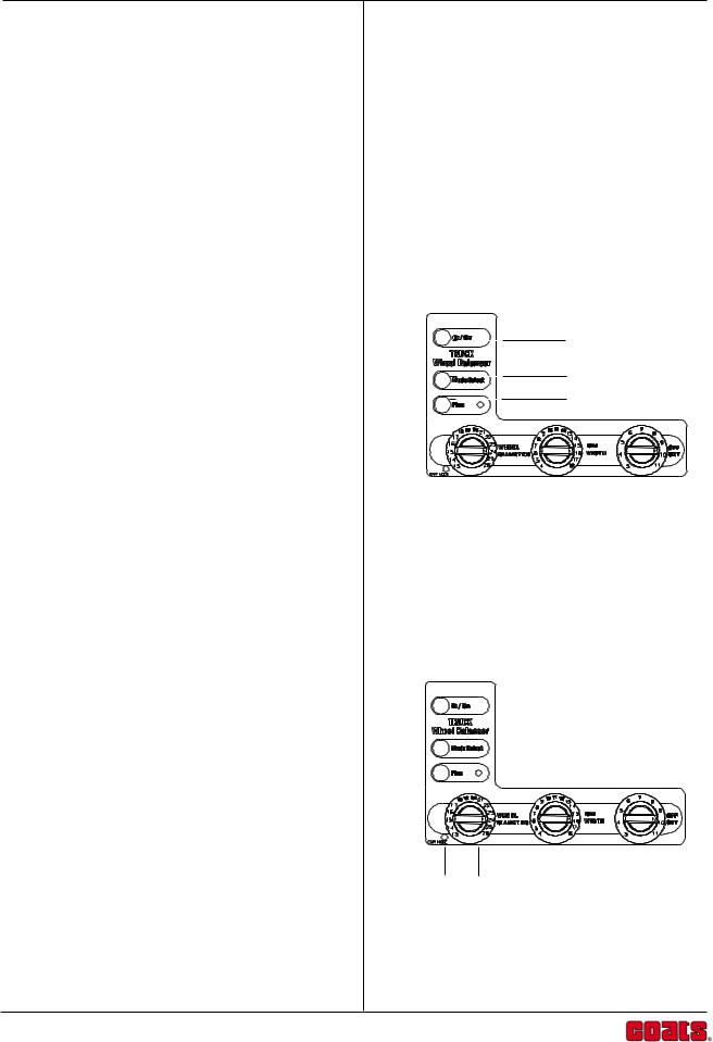
Input Panel
The input panel combines controls and indicators, positioned for convenience, with graphical symbols clearly defining each function.
The input panel is used to select and indicate specific operating states and to enter data for the wheel to be balanced and the weights to be used.
1. Ounce/Grams Button
This button is used to select Ounce/Grams and Calibration. To change from ounces to grams or viseversa, hold the Ounce/Grams button while pressing the "Fine" mode button.
2. Mode Select Button and Weight Location LED
Indicators.
The Mode Select Button works in conjunction with the Weight Location LED Indicators on the Display, to select the correct balance weight location. Weight requirements are automatically recalculated when the Mode is changed.
For easy and accurate custom mode operation, do the balancing operation in the NORMAL (clip-on) Mode. Then press the Mode Select Button for the desired custom weight location. The balancer will automatically recalculate the amount of weight required for the selected weight location.
3. Fine Button.
Switches the balancer between Standard and Fine resolution. The Fine LED Indicator lights when the balancer is in Fine resolution.
4. Rim Diameter Knob.
Turn the Rim Diameter Knob to set rim diameter as shown on the tire sidewall. Read the selection in the Display Window.
5. MM Indicator.
Turning the Rim Diameter Knob fully counter clockwise
allows the rim diameter to be set in millimeters. When 5 4 the MM LED is lit the Display Window will show the
diameter in millimeters.
1
2
3
6
 Loading...