

Clockaudio CCRM 4000-Retracta Installation Manual And User's Manual
CCRM 4000-Retracta Motorized Ceiling
Microphone
Installation Manual and user Guide
1
Contents Page
Contents 1
Features 2
Parts supplied 3
Connections 4
Installation 5-8
Controls 9
DSP Connections 10
Mute Control 11
Master to DSP Connections 12
Slave Connections 13
IR Remote Control 14
Remote Control Information 15
Programming Master Cable Height 16
Programming Slave Cable Height 17
Microphone Angle Adjustment 18
Horizontal / Vertical Mounting 19
Slave Communication Link 20
Cautions / Troubleshooting 21
Specification 22
Warranty 23
IMPORTANT SAFETY INSTRUCTIONS
Read these instructions carefully as they contain important information
concerning safety and safe operation of this equipment..
Heed all warnings in this manual they are there for the safety of you and others.
Keep these instructions in a safe place in case they need to be referred to later.
Do not install near sources of heat or water. Clean with dry cloth only.
Use only with the bracket supplied.
Do not burn or incinerate the remote control battery. Danger of explosion.
WARNING: Do not connect a supply Voltage until the CCRM 4000 is fixed securely in
place, IR sensor connected (if fitted / Master only), Ceiling bezel is mounted in the
ceiling tile, microphone and magnet has been passed through the Ceiling Bezel and
all other connections have been made.
Do not power the system off when the cable is fully extended. Always retract the cable back
to the ceiling bezel after use.
Do not angle the microphone more than 40 degrees or it will become jammed In the
bezel

2
Features
Control ports allow DSP connection and Link / daisy chain expansion to other
CCRM 4000 Retracta units.
A positive (+2.5V to +12V) signal applied to the MASTER DSP control port will
simultaneously operate all slave units connected to the master.
Logic Hi / Lo for DSP mute detection port.
Master & Slave units are Identical in construction. Two rotary 0-9 digital
decimal encoders are used to set Master (00) and 01 – 99 determines slave
designation. The factory default is set to Master (00).
XLR socket allows easy and fast connection of the audio to mixer or DSP. A
9-48 Volt phantom power is required.
IR remote control is supplied with the master unit. Remote control can be
used to activate the units in the absence of a DSP.
IR receiver sensor with integral green programme mode led and red range led
(supplied with master unit).
Audio cable length 2.5 Metres.
Supplied with 350 degree rotation, 40 degree knuckle joint angle microphone
with cardioid polar pattern.
Up to 99 slave units can be daisy chained to the master.
Ceiling bezel fitted with detection switch.
Universal mains switched mode power supply available as separate item.
Operates up to 4 units.
Automatic safety detection for cable hang-ups.

3
Parts supplied with CCRM- 4000 Master
1. CCRM-4000 Retracta unit complete with microphone
2. IR receiver sensor (CCRM-4000-IR)
3. IR remote control (CCRM-4000-R)
4. 2 x wall fixing brackets
5. Safety hook and wire harness
6. Installation manual
7. Ceiling tile fixing bracket (CCRM-4000-Rack)
8. White ceiling Bezel with pulley (CCRM-4000-BW)
9. 18 VDC universal power supply (PS-018)
Parts supplied with CCRM-4000 Slave
1. CCRM-4000 Retracta unit complete with microphone
2. White ceiling Bezel with pulley (CCRM-4000-BW)
3. 2 x wall fixing brackets
4. Safety hooks and wire harness
5. Installation manual
6. Ceiling tile fixing bracket (CCRM-4000-Rack)
4
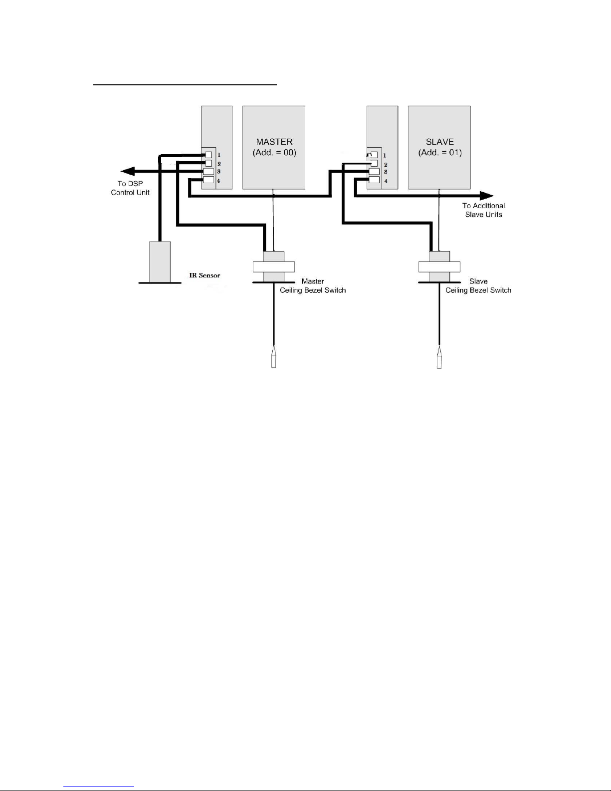
CONNECTIONS BLOCK DIAGRAM
Important: When using a DSP to control the system make
sure that the DSP control signal is already outputting to
SK3 on the CCRM 4000 master (+2.5 to 12 Volts) before
powering the system up otherwise the DSP command will
not be recognised by the system and will fail to operate.
5
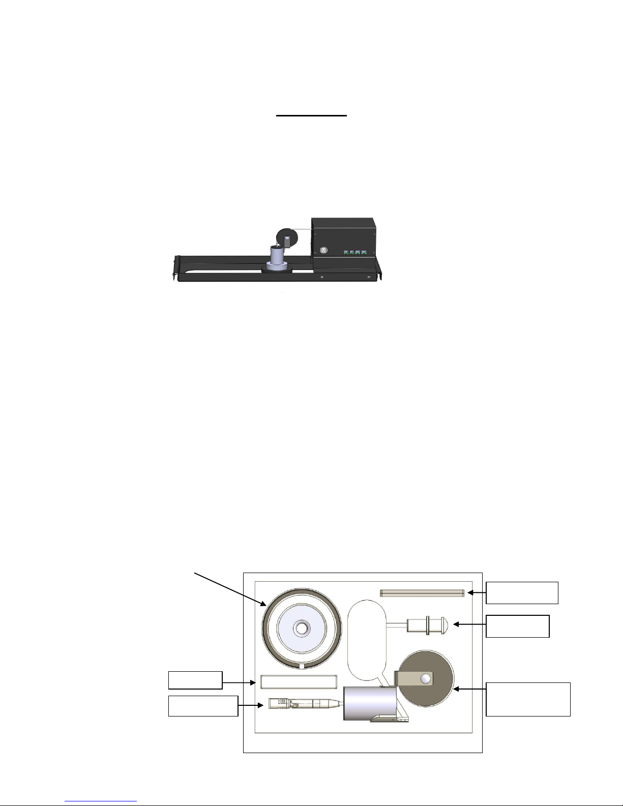
Installation
The CCRM 4000 is supplied partially disassembled and simply requires reassembly /
push to fit. Below is picture of the fully assembled unit.
To prevent unnecessary damage to the system it’s vitally important to follow
the instructions below:
1. Remove the CCRM 4000 system from its transportation box and remove the 2
foam end caps.
2. Cut the tape securing the large cardboard box to the large black ceiling frame.
3. Carefully move the box out of the ceiling frame and set to one side being
careful not to snag or cause the microphone cable to kink. Do not remove
the microphone and pulley assembly at this stage.
4. Remove the small cardboard box located under the CCRM 4000. This
contains the PSU (master only).
5. Now open the large cardboard box and remove from the packaging the large
lower bezel with bezel clamp.
Wall mount
IR sensor
Remote
Top bezel with
pulley
Microphone
6
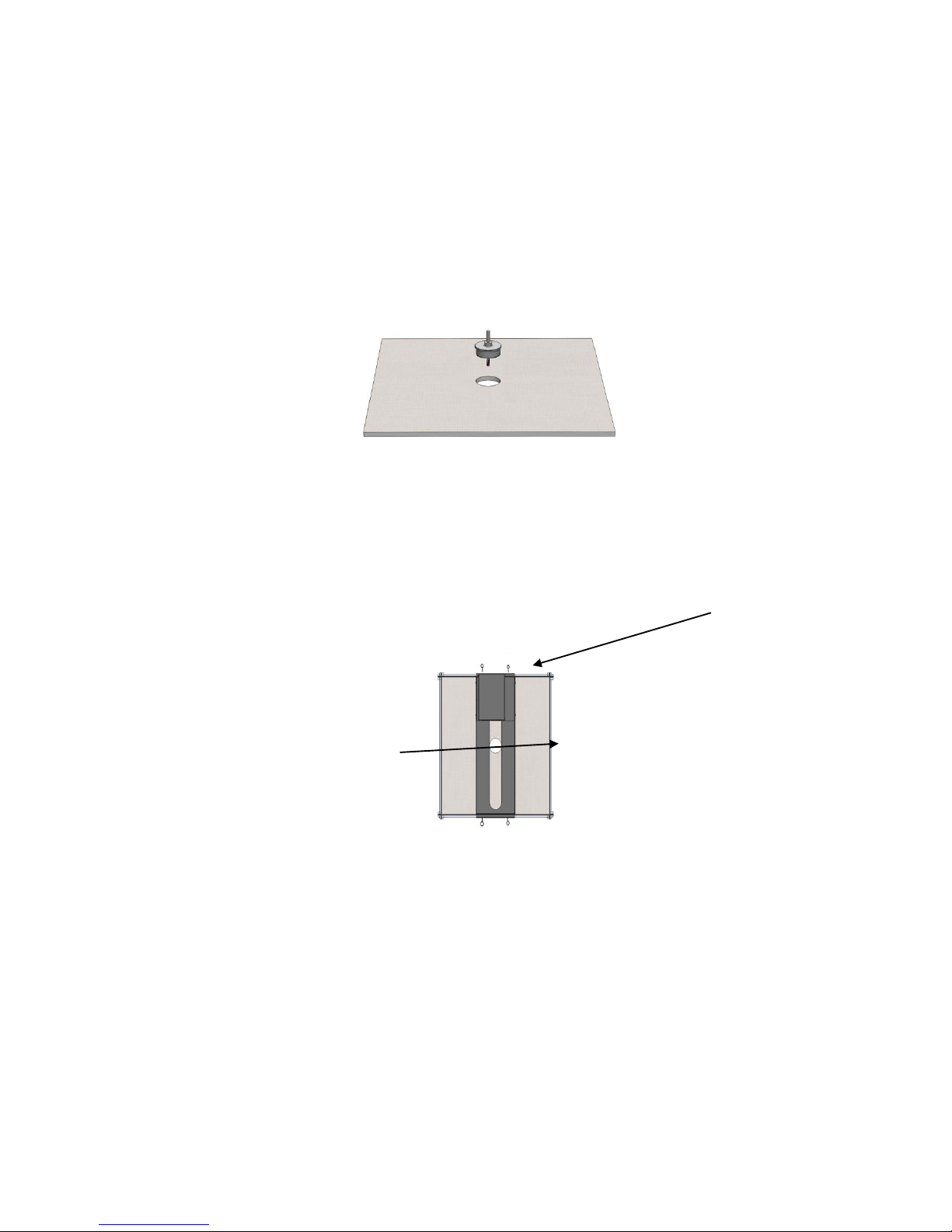
To install this system a (65 mm) (2.5") hole must be cut into the ceiling tile to allow
the large lower bezel just removed from the packaging to be fixed to the tile. The
hole should ideally be cut in the centre of the tile and must not be closer than
(76mm) (3") from the edge of the tile or it will not be possible to align the CCRM
4000 support bracket over the hole.
Take the entire CCRM 4000 kit up to the final location site. Carefully align the
CCRM 4000 complete with ceiling tile bracket so that the large slot is directly
over the hole that has previously been cut in the ceiling for the bezel. Make
sure that the front and back of the bracket fits snugly over the ceiling tile “TBar rails”. Secure the ceiling bracket to the T Bar rails using the four eye bolts
finger tight.
(65mm) 2.5" Hole
Insert the bottom part of the bezel up through the ceiling tile through the hole
and slot in the tile bracket. Secure the bezel in place with the securing ring.
7
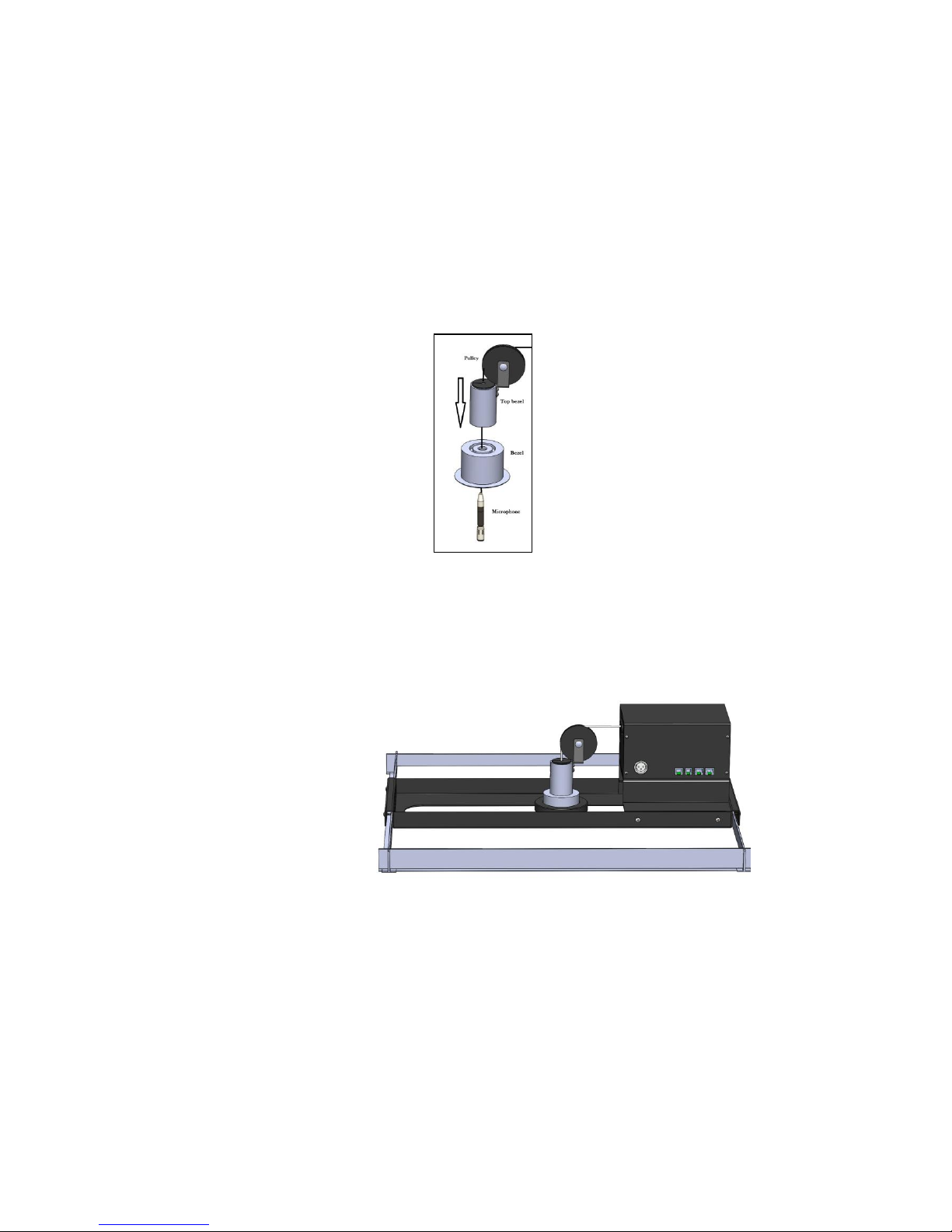
Now carefully remove from the foam packing the IR sensor, pair of metal
fixing brackets with screws, remote control and 4 cable fixing kits and set
aside. Next remove the top bezel containing the pulley along with the
microphone and magnet assembly.
1. Remove the protective covering on the microphone and insert the
microphone through the lower ceiling bezel and then push fit the top part
of the bezel to the lower bezel making sure the magnet is inside the top
part of the bezel.
2. Carefully twist the bezel around until the pulley / cable is in alignment with
the cable exiting the CCRM 4000. Lift the cable over the top of the pulley.
Any kinks or bends in the cable can be straightened by gripping the
cable with your hands and passing it through a clean dry cloth a few
times.
 Loading...