

Page 1
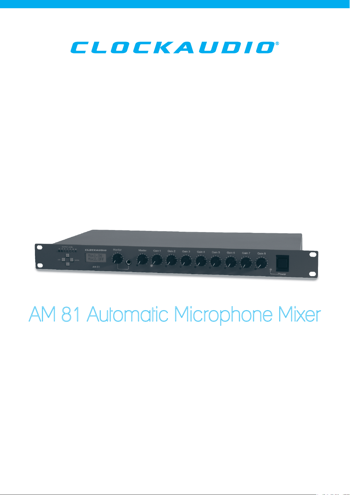
AM 81 Automatic Microphone Mixer
Operation and Installation Manual
version 2.0
www.clockaudio.com
Page 2

Contents:
Introduction ----------------------------------------------- 03
Product Overview --------------------------------- 04~05
1 Features
2 Front Panel Layout
3 Rear Panel Layout
4 LCD Panel and Controls
5 Dimensions
Connecting your AM 81 ------------------------------- 06
1 Power
2 Microphone Inputs
3 Master Output
4 Pre-Amplifier Outputs
5 External Control Function
6 Expansion Options
Installation and Set-Up --------------------------------- 07
1 Priority Channel Configuration
2 Priority State
3 Reset
Detailed Settings ---------------------------------- 08~09
1 Switching for Pre-Amplifier Output
2 Gate Attenuation Adjustment
3 Maximum Gate Attenuation
4 Limiter Switch
5 Adjusting Limiter Levels
6 Output Levels
7 NOMA Settings
8 NOMA Level Adjustment
9 Phantom Power
Final Checklist -------------------------------------------- 11
Technical Specification -------------------------------- 11
Security & Safety ---------------------------------------- 11
02
Page 3

Introduction:
Clockaudio AM 81 is an 8 channel automatic microphone mixer ideal for
multi channel microphone systems in conference and voice reinforcement
applications.
By automatically sensing when a channel becomes active the AM 81 will simply
control the level of the system dependant on the priority settings, the NOMA
(number of open microphones Attenuated) function will also control and adjust
the mixer output to prevent feedback due to open microphone channels.
Expansion is easily achieved with up to 15 units able to be cascaded for medium
to large system applications (120 microphones maximum).
03
Page 4
Product Overview:
1 Features
• 8 x Microphone Inputs
• 1 x Aux/Music Input
• Individual Priority settings
• Main Output (Balanced)
• 8 x Individual Pre-Amp Outputs
• Simple LCD Display (to view and change settings and functions)
• Automatic or Manual operation.
• NOMA facility (number of open microphones Attenuated)
• Link In /Link Out for multi system use.
• Free Standing Case supplied with optional 1U 19” Rack Mount Kit as standard.
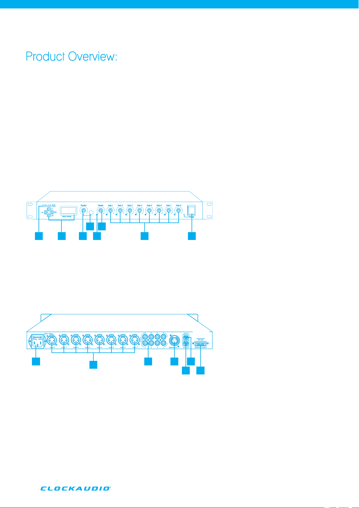
2 Front Panel Layout
See Drawing and numbered features.
6
1
2
345
7 8
1 Output Level Indicator
2 LCD & Control Panel
3 Monitor Earphone Level Adjustment
4 1/4 Headphone Socket
3 Rear Panel Layout
See Drawing and numbered features.
1 3 4
1 Fused Mains IEC Input
2 MIC Inputs
3 Pre-Amp Outputs
4 Master Audio Output
2
5 Master Output Signal Indicator
6 Master Output Level Adjustment
7 Channel Input Gain
8 Power Switch
657
5 Cascade/Link Ports IN
6 Cascade/Link Port OUT
7 External Control Port
04
Page 5
4 LCD Panel and Controls
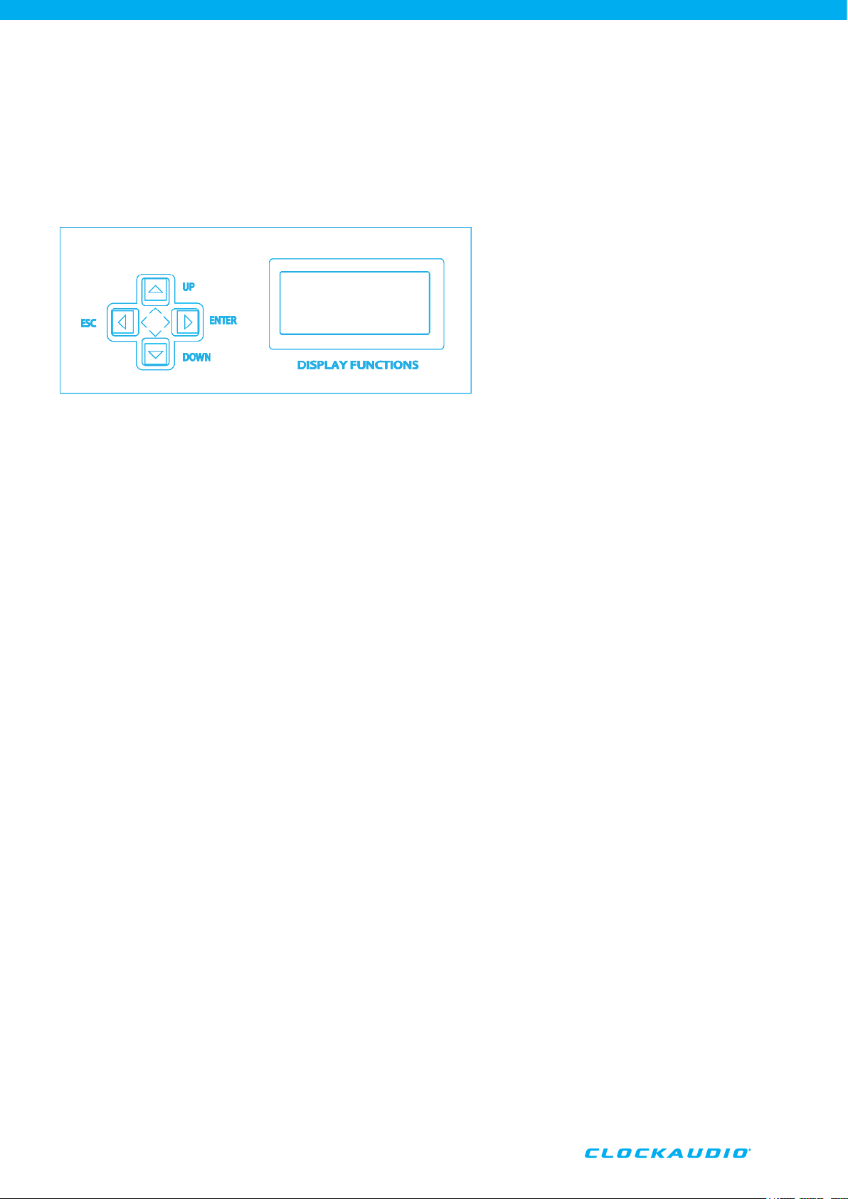
Individual functions and mixer set up is achieved using a simple LCD display and 4 button
control panel (Enter, Up, Down and Escape)
Start Up Screen: shows model number.
Enter: to execute the screen menu function and open the configuration screen.
ESC: to quit the current location and return to the previous menu.
Up/Down: to move through the menu structure.
Note: whilst in the menu function the back light will automatically turn off if a button is
not pressed for approx. 10 seconds, pressing any of the function buttons will re-activate
the back light facility.
5. Dimensions
Dimensions: 48(H) x 430(W) x 221(D)mm
Weight: 3.2kg
05
Page 6
Connecting your AM 81
1 Power
The mains power is connected via the fused IEC
connector on the rear panel, power source should be
220vAC~50Hz.
2 Microphone Inputs
Microphone Inputs: The 8x Microphone Inputs are
provided via 3pin XLR-Female type connectors.
Inputs may be configured to accept both Condenser
type microphones, the mixer providing a +48v Phantom
Power facility or Dynamic Balanced type microphones.
If connecting external equipment other than
microphones, these devices where possible, should be
connected at Microphone Signal Output level, to prevent
overdriving/distortion of the input signal.
3 Master Output
The Master Output is used to connect the mixer to the
system amplifier, processor or recording device, via
balanced XLR~M connector.
Internal settings inside the mixer can be configured
to provide different output configurations, including
Microphone or Line Level Output options.
4 Pre-Amplifier Outputs
Pre-Amplifier Outputs are provided via mono Phono type
connectors, the level from each output is 550mv 3.3K
ohms. These outputs can be used for recording individual
or groups of channels.
Operation of the Pre-Amplifier outputs can be configured
to operate “Before” or “Behind” the gate control.
If set to “Before” the output from the Pre-Amplifier Output
(Ch1~8) will output a signal, regardless of if the channel
gate is open or closed.
If set to the “Behind” option the output from the
Pre-Amplifier is controlled by the individual gate control
of the channel, when the gate is open the audio signal is
passed via the relevant Pre-Amplifier Output connector
(Ch1~8), and when the gate is closed the audio signal
is cut off.
5 External Control Function
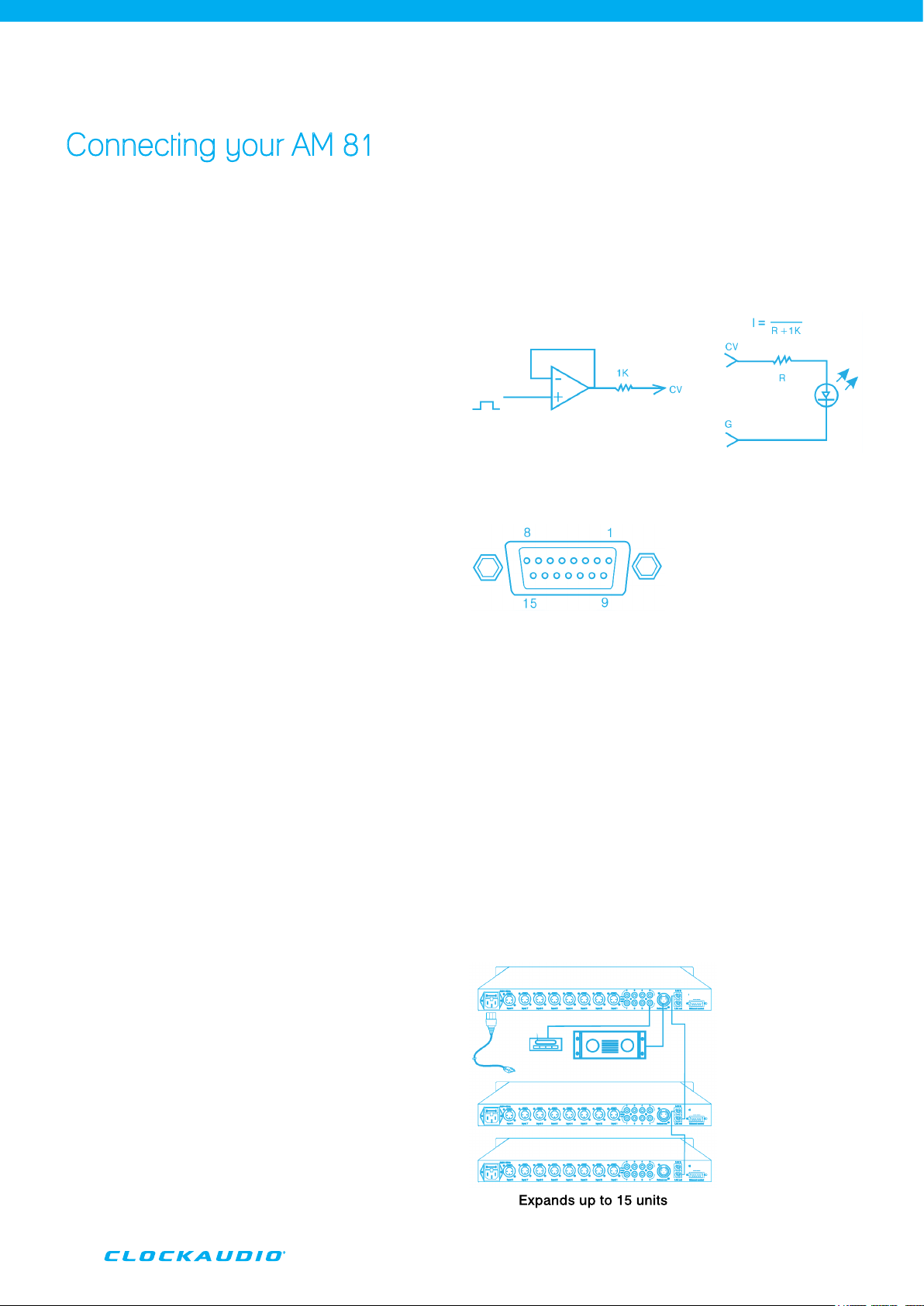
This remote control feature is provided via a 15pin D Type
connector.
Pins 1~8 control the gain level for each channel, as well
as providing switched voltage free outputs for controlling
external relays and devices or LED’s.
The following references can be used.
Inner Output Connect to LED
PIN Instruction for External Controller Output Port:
1 Channel 8 ON/OFF controlling signal
2 Channel 7 ON/OFF controlling signal
3 Channel 6 ON/OFF controlling signal
4 Channel 5 ON/OFF controlling signal
5 Channel 4 ON/OFF controlling signal
6 Channel 3 ON/OFF controlling signal
7 Channel 2 ON/OFF controlling signal
8 Channel 1 ON/OFF controlling signal
9 Ground 10. Ground 11. NC 12. NC 13. NC 14. NC 15.
6 Expansion Options
If using the AM 81 as part of a larger system the ability to link
units together is an option, units can “daisy chain” together
via multi pole “Link In” and “Link Out” connections.
Up to 15 units may be configured in this way to
provide a fully functioning system with a capacity of up to
120 microphones.
06
Page 7
Installation and Set-Up
1 Priority Channel Configuration
Microphones allocated as Priority can gain access at any
time, normally the priority microphone is used by the Chair
Person of a conference for example to override the other
microphones on the system.
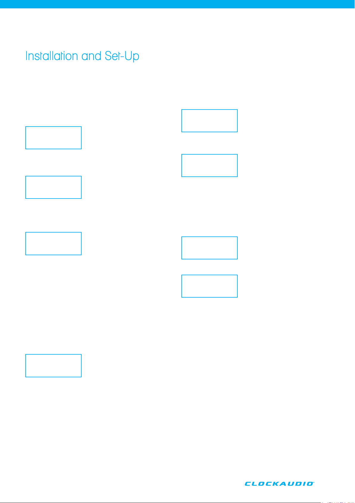
Press the
Enter button to enter the configuration screen.
1.SetMic
2.State
Using the
Up/Down buttons choose 1.SetMic.
1.SetMic
2.State
On each channel the priority is activated using the
button.
Enter
MIC1.OFF
MIC2.OFF
2 Priority “State”
It is possible to show the priority status via the LCD panel
display.
From the menu using the
2.State.
1.SetMic
2.State
Pressing the
channels which are set to priority.
Enter button will provide a numeric list of
Up/Down buttons select
P: 2 . 3 . 4 .
5 . 6 . 7
3 Reset
By using this function it is possible to clear all priority
settings previously set on the mixer.
From the menu using the
3.Reset.
3. Reset
Up/Down buttons select
When priority is activated, it will show the input as
Move through each microphone setting via the
buttons repeating the above until the desired priority is
achieved.
When Priority is selected on any channel the corresponding
LED illuminates on the front panel of the console to visually
indicate the channel status.
It is possible to activate all channels as priority.
From the
Down buttons to the Manual. screen.
Manual: Y
N
Press the
(no priority) or Y. (all priority). This option will override any
individual channel settings if already in place, removing
this setting will also revert the mixer back to any previous
individual settings.
In the
front panel of the console to visually indicate the channel
status.
1.SetMic screen move the cursor via the Up/
Enter button to change the setting between N.
Y. setting all the channel LED’s illuminate on the
ON.
Up/Down
Pressing
Reset? Y
N
If no priority channels are selected the AM 81 automatic
mixer will open only the first active channel to operate, only
one channel can be active in this state.
When a priority channel is activated whilst a no priority
channel is active then the priority channel will override,
reducing the non priority level by -40dB (this level can be
adjusted between -20dB and -40dB, with -40dB as the
default).
If a non priority channel is activated whilst a priority channel
is active then the non priority channel will not become active
until the priority channel has become inactive.
When only priority channels are active then there will be no
attenuation between active channels, they will all output
at the same level.
If the system is configured as all channels with priority, the
AM 81 will automatically adjust/attenuate the output level
to prevent feedback.
Note: It is highly recommended that the maximum number
of channels set up with priority is 4. By limiting this to 4 the
possibility of feedback via the system is greatly reduced.
Enter will provide the option to reset Y. or N.
07
Page 8

Detailed Settings
See printed details on inside of AM 81 lid for location of switch and potentiometer locations
1 Switching for Pre-Amplifier Output
Each output may be configured to operate before or behind the gate, this is programmed
via switches on the main PCB as follows:
Ch1 Ch2 Ch3 Ch4 Ch5 Ch6 Ch7 Ch8
SW8 SW10 SW12 SW14 SW16 SW18 SW20 SW22
2 Gate Attenuation Adjustment
Attenuation of each of the individual Pre Amplifier outputs is adjusted via a series of
potentiometers as follows:
Ch1 Ch2 Ch3 Ch4 Ch5 Ch6 Ch7 Ch8
VR1 VR2 VR3 VR4 VR5 VR6 VR7 VR8
3 Maximum Gate Attenuation
Two levels of attenuation are available -20dB or -40dB, this is selected via the marked
switches on the main PCB as follows:
Ch1 Ch2 Ch3 Ch4 Ch5 Ch6 Ch7 Ch8
SW7 SW9 SW11 SW13 SW15 SW17 SW19 SW21
Selecting the -20dB option with the gate closed will provide an output signal to the main
output, however in the -40dB position there is no output signal to the main output.
NB The factory default is set at -40dB.
4 Limiter Switch
Each channel has the option to select on or off the limiter circuit, this is selected via the
marked switches on the main PCB as follows:
Ch1 Ch2 Ch3 Ch4 Ch5 Ch6 Ch7 Ch8
SW23 SW24 SW25 SW26 SW27 SW28 SW29 SW30
With the limiter switch in the off position the gain from the main output will increase
to18dBV, the level from the corresponding Pre Amp output will also increase.
NB it is recommended that the volume of the selected channel is reduced to compensate
this increase.
5 Adjusting Limiter Levels
It is possible to adjust the limiter levels for each channel, this is selected via the marked
potentiometers on the main PCB as follows:
Ch1 Ch2 Ch3 Ch4 Ch5 Ch6 Ch7 Ch8
VR9 VR10 VR11 VR12 VR13 VR14 VR15 VR16
Adjustment of these controls will vary the maximum output volume for each channel from
the main output of the mixer.
6 Output Levels
The AM 81 main output is provided via a 3pin XLR~M connector and is balanced, and
is factory set at 0dB/line level. It is possible to change this output via SW5 on the main
PCB, this will change the output to -50dB/mic level.
08
Page 9
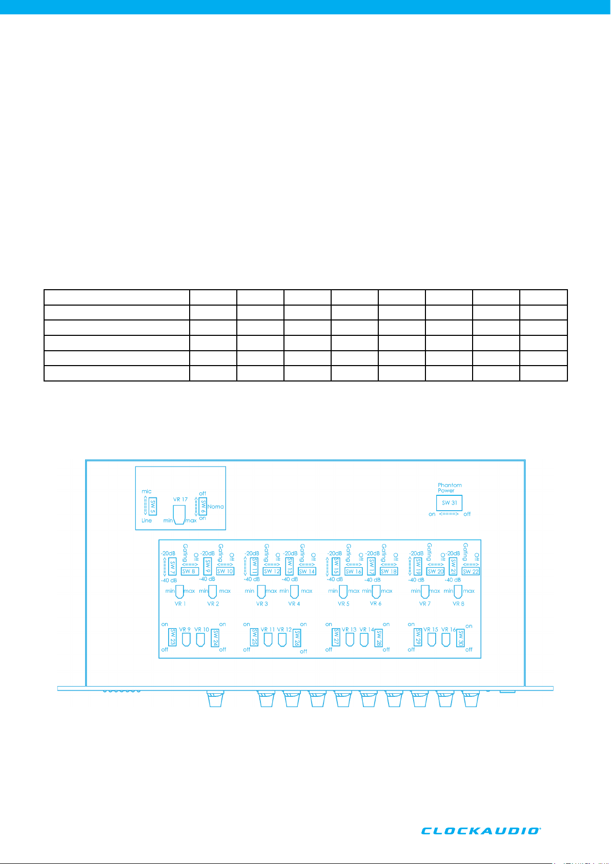
7 NOMA Settings
To enable or disable the NOMA function of the mixer please use SW6 located on the
main PCB. If using the AM 81 in a larger multi mixer configuration it is recommended that
the NOMA facility is switched off and any adjustments to gain levels should be made
manually.
8 NOMA Level Adjustment
The NOMA levels are preset at the factory, it is not recommended to make any adjustment
to this facility as this can dramatically affect the performance of the mixer.
Variable potentiometer VR17 on the main PCB will allow any adjustments.
Table of Switches/Adjustments
Channel Ch1 Ch2 Ch3 Ch4 Ch5 Ch6 Ch7 Ch8
Switch for Limiter Level VR9 VR10 VR11 VR12 VR13 VR14 VR15 VR16
Switch for Limiter SW23 SW24 SW25 SW26 SW27 SW28 SW29 SW30
Switch for Max Gain Attenuator SW7 SW9 SW11 SW13 SW15 SW17 SW19 SW21
Switch for Pre-Amplifier Output SW8 SW10 SW12 SW14 SW16 SW18 SW20 SW22
Gate Attenuation Adjustment VR1 VR2 VR3 VR4 VR5 VR6 VR7 VR8
9 Phantom Power
Phantom Power is provided across all microphone channels preset at +48v. This facility
can be switched off by using SW31 located on the main PCB.
09
Page 10
Final Checklist
Technical Specification
Once all individual settings and configurations have been
made to the internal control of the AM 81 it is recommended
the following procedure is followed when connecting
and commissioning the system, it may be an idea to have
someone to assist you when carrying out this procedure.
1 Turn down the gain levels of the amplifier or host
equipment or disconnect the mixer unit from the
amplifier or host equipment.
2 Reduce the gain level of the Master and Input Channels
(1~8) on the mixer front panel to the minimum position,
also reduce the level of any connected amplifier if
still linked.
3 Connect the power lead and switch on the mixer, the
unit will automatically check the status for each
channel.
NB 48v Phantom Power is provided for each microphone
channel, the wiring for each input must be balanced,
please ensure correct configuration prior to
installation.
4 Set the input gain control for the required channel to
approx 9 o’clock, if the channels are each set up
with different input sensitivity adjust individually to
provide an equal gain level.
5 Firstly test the channels not configured as priority
channels.
Using the installed microphones speak clearly into the
individual microphone, check both the audio output
signal via the headphone socket and the visual channel
indicator on the front panel of the mixer.
6 Secondly test the channels set up with priority.
Priority channels are active simultaneously, speak into
the microphone connected to the priority channel and
check the visual indicator on the front panel.
Next speak into the microphone of the priority channel
whilst a colleague is speaking into a non priority channel,
the level of the no priority channel should reduce/
attenuate by up to -40dB.
7 Once satisfied with the above test procedure, set the
mixer to the desired operational levels and increase the
levels or re-connect the host amplifier/equipment.
In many typical applications the Chairman’s microphone
position is usually set up with priority, in this scenario please
do not locate the chairmans microphone close to or facing
any installed loudspeakers. Because this microphone is
likely to be active for long periods we advise taking the
above guidance to avoid any potential for the microphone
picking up the loudspeaker signal and preventing the
opportunity of any feedback issues.
Input Impedance MIC 4300W, AUX 50KW
Output Impedance (balanced) MIC 15K
Output Impedance (unbalanced)
Pre-Amplifier Output Impedance
Max Input Level MIC -18dBv, AUX 6dBv
Max Output Level (Balanced) MIC -18dBv, Line 21.5dBv
Standard Input Level (Balanced) MIC -28dBv, Unbalanced
Pre-Amplifier Output Level
(Balanced)
Pre-Amplifier Output Level
Max Gain
Frequency Response
Noise All channels with the max
THD+N ≤0.5%
S/N 75dB
Phantom Power
Controlling Output Voltage
Power Voltage
Current Consumption
Dimension 48(H) x 430(W) x 221(D)mm
Weight 3.2kg
1KW
3.3KW
AUX 2.5dBv
MIC -25dBv, Line 0dB
-4.4dBv
62dB
20Hz~20KHz
gain position (220W) -85dB
+48v
5v
AC220v
25W
W, Line 220W
Security and Safety
• To prevent the potential for electric shock please take
extreme care in making any adjustments or altering any
settings.
• Whilst the unit is DC powered ensure that no contact is
made to the Power Supply or DC Power Jack.
• Please check the Supply Voltage is correct prior to plug
in and switch on.
• When configuring internal settings please use an
electrically insulated tool or plastic implement to operate
any switch settings or adjust any level controls.
• When installed make sure the unit is earthed/grounded
correctly.
• Do not use the mixer in conditions of extreme dust or
extreme humidity.
DANGER!
PLEASE ENSURE THE POWER SUPPLY
IS SWITCHED OFF BEFORE REMOVING
THE TOP COVER TO MAKE SYSTEM
ADJUSTMENTS.
10
As part of a continuous product improvement programme, we
reserve the right to alter specifications without prior notice.
Page 11

NOTES
11
Page 12

T: +44 (0) 23 9225 1193 F: +44 (0) 23 9225 1201 E: [email protected] W: www.clockaudio.com
Clockaudio Ltd 22 Arnside Road Waterlooville Hampshire PO7 7UP England
 Loading...