

Page 1
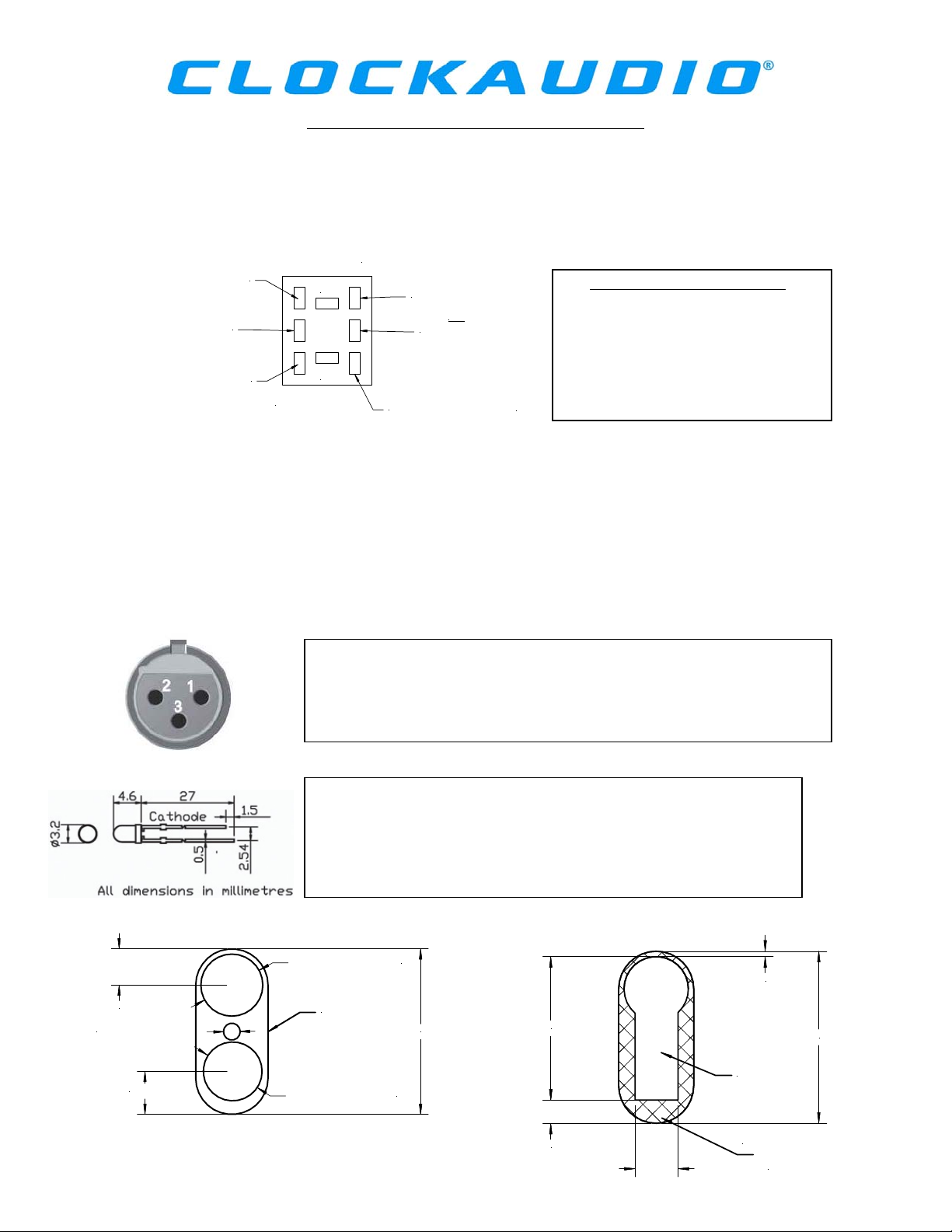
Wiring Instructions for SWP-PTT and SWP-Latch
The Switch Plate shall house a 3mm Super bright red LED and either a Push to Talk switch (SWP-PTT) or a
Latching switch (SWP-Latch). Although having different operations, both switches have the same
appearance and can be wired in identical ways. The switch can be wired for Push to mute (NO) or Push to
talk (NC) operations by using 2 out of the 3 solder tags down either side of the switch as shown in the
diagram below:
Audio from Pin 2 of Female XLR
(states NC on switch)
Audio from Pin 2 of female XLR
(states NO on switch)
Audio from Pin 3 of Female XLR
(states COM on switch)
+
-
LED + 2.5V DC (NC)
OR
LED + 2.5V DC (NO)
Cathode from LED (COM)
Calculating the LED series Resistor
R = (Vs – Vf) / If
If = 20mA Vf = 2.5Vdc
R = resistor Vs = Supply Voltage
Should you require the audio to be off when the switch is pressed simply connect Pin 2 of XLR to “NO” and
Pin 3 to COM.
The switch also includes an internal LED which has an operating voltage of 2VDC and current rating of
30mA.
If you should require the LED to be off when the switch is pressed simply connect the Anode to “NO” and
cathode to COM. (The cathode is identified by having a shorter leg)
The female XLR shall be cabled and connected as normal to your mixer.
Simply use equipment wire from Pin 2 of XLR to switch thus giving you
two wires into Pin 2 that of mixer and switch. Also use equipment wire
from Pin 3 of XLR to switch.
The LED shall be attached with the anode to “NO” or “NC” on the
switch and the cathode to “COM”.
A separate 2.5V DC power source is required. To operate using a
higher voltage power source use the formula shown to calculate the
resistor required.
14.00 mm/ 0.55"
ø 6.50 mm/ 0.25" Cut Out
16.70 mm/ 0.66"
ø 24.00 mm/0.95" Cut Out
Switch plate
64.00 mm/2.52"
ø 23.00 mm/ 0.9" Cut Out
www.clockaudio.co.uk
54.00 mm/ 2.12"
8.00 mm/ 0.3"
2.00 mm/ 0.08"
64.00 mm/ 2.52"
Cut Out
Switch Plate
16.00 mm/ 0.63"
 Loading...