

Page 1

CLOCKAUDIO
MR88 Automatic Microphone Mixer
Version 4.2
Clockaudio Limited,22 Arnside Road
WATERLOOVILLE
Hampshire. UK
Tel : +44 (0)2392 251193 Fax : +44 (0)2392 251201
Email : sales@clockaudio
.co.uk
Page 2

CONTENTS
INTRODUCTION............................................................................................................ 3
Features............................................................................................................................. 4
MR88 Front Panel ............................................................................................................ 5
MR88 Rear Panel ............................................................................................................. 6
MR88 Menu Functions..................................................................................................... 7
Changing Channels and Functions............................................................................... 9
Changing Values. ......................................................................................................... 9
Explanation of Functions................................................................................................ 10
Output A+B Functions: .............................................................................................. 10
Functions of Channels 1 – 8:...................................................................................... 10
Mono/Stereo ............................................................................................................... 10
Line/Mic/Phantom...................................................................................................... 10
Gain Control - Pre-Amplifier ..................................................................................... 10
Compression............................................................................................................... 11
Equaliser..................................................................................................................... 11
Output - Selection....................................................................................................... 11
Priority Select Function.............................................................................................. 11
Gating – Off Attenuation Level Control .................................................................... 11
Detector - Adjustable Detector Control...................................................................... 12
Hold - Time ................................................................................................................ 12
NOMA (Number of Open Microphones Attenuated) Control ................................... 12
System Functions: .......................................................................................................... 13
Priority........................................................................................................................ 13
Last Active Channel ................................................................................................... 13
Security Code ............................................................................................................. 13
Active Control Outputs............................................................................................... 14
Control Inputs............................................................................................................. 16
VCA - Control............................................................................................................ 17
External Control Port...................................................................................................... 18
Link In/Out - Daisy Chain Capability ............................................................................ 19
RS232 Control................................................................................................................ 19
Installation...................................................................................................................... 20
Basic Set-up for Microphones.................................................................................... 20
Security Mode ................................................................................................................ 21
How to Change the Security Code: ............................................................................ 21
How to Lock the Mixer: ............................................................................................. 21
How to Unlock the Mixer:.......................................................................................... 21
Lost Security Code:.................................................................................................... 21
Specifications ................................................................................................................. 22
Page 2
Page 3

INTRODUCTION
The MR88 automatic microphone mixer incorporates advanced DSP
technology. It has been carefully designed to give outstanding performance
and flexibility while maintaining simplicity of set up and use. Eight input
channels, fully adjustable for microphone and line levels, can be set up to be
put onto either or both of the two output channels. Active input channels can
be automatically detected. Each input channel can be set to a multi-level
priority system. This allows "one at a time operation", "all channels active" or
combinations with chairman priorities. When no one is talking, a constant
ambient sound can be maintained through the system by setting the last
microphone selected to automatically stay on. Mixers may be chained
together to make a large multi-source system with priority and NOMA
information extending throughout. With two independent output channel
busses provided, the MR88 to be used as a genuine 8 X 2 mixer.
The input level control and priority system of this mixer makes it uniquely
versatile for many diverse applications. The MR88 mixer is ideal for places of
worship, courtroom proceedings, meetings, seminars and general A/V
applications.
The MR88 uses microprocessor control and provides full setup and control of
the mixer via a user-friendly LCD interface on the front panel. This allows the
mixer settings to be selected and adjusted without the need to remove the
case covers. All settings are retained, even when the mixer is disconnected
from the mains power supply. The mixer front panel can be easily 'locked'
with an adjustable four digit security code to prevent the mixer settings being
accidentally changed, or to 'tamper proof' the settings.
The MR88 also has the ability to be daisy chained with other MR88 mixers
via a link cable (available separately), to give a multi-mixer system.
Page 3
Page 4

Features
Input Features
• 8 Channel balanced mic/line inputs on XLR connectors.
• 48V phantom power selectable for each microphone input channel.
• Assignable input pairs for stereo sources.
• Adjustable compressor for each input channel.
• 2 Band Equalisation on each input channel.
• Adjustable off attenuation for each channel.
• Detector modes for speech, music and manual threshold level.
• Adjustable detector hold time for each input channel.
• Four levels of assignable priority for each input channel.
• Recorder outputs for each input channel.
• NOMA compensation selectable for each channel
• Assignable to either or both output channel busses.
Output Features
• 2 Channel balanced line outputs on XLR connectors.
• Independent or linked gain control of output channels.
• Mixed output available from any mixers in chain for multi-zone control.
System Features
• Easy set up with LCD display of all functions and settings from front
panel.
• LED level meter to monitor any input or output channel.
• Monitor headphone output to monitor any input or output channel.
• Mixers can be linked to create larger systems of microphones.
• Each priority can be set for inclusive (all channels active) or exclusive
(one at a time operation)
• Selectable last microphone on operation to maintain ambient sound.
• Security mode to protect settings.
• External VCA control of output channel gains.
• External logic level control and monitoring of channel selection.
Page 4
Page 5
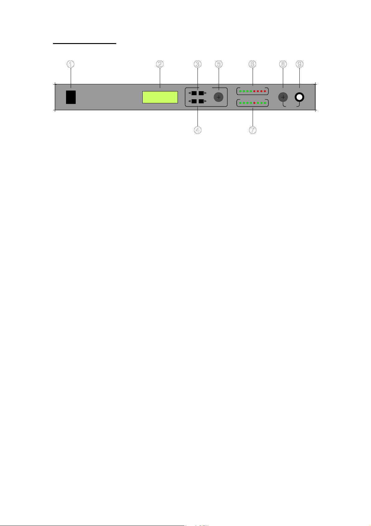
MR88 Front Panel
Power
Monitor
-201-10
O/L
Channel
CLOCKAUDI O
MR88
1) Power Switch.
2) Display. Displays selected channel/function and settings for each.
3) Channel Buttons. Select between System settings, Output channels A
and B, and Input Channels 1-8.
4) Function Buttons. Selects set-up functions for each channel.
5) Rotary Control. Adjusts the settings on each function.
Output LevelControls
+6
Function
Selected Channel
2-63-3405+36 7 8
6) LED Level meter Indicates peak output level of the selected channel in
dB.
7) The Selected Channel LEDs indicates which microphone is currently
in use and which other microphones are being "locked out"
(attenuated). Green is active and Red is locked out.
8) Monitor Volume Control. Adjusts headphone amplifier volume.
9) Headphone Output. 1/4" TRS jack. Monitors the selected channel.
Page 5
Page 6
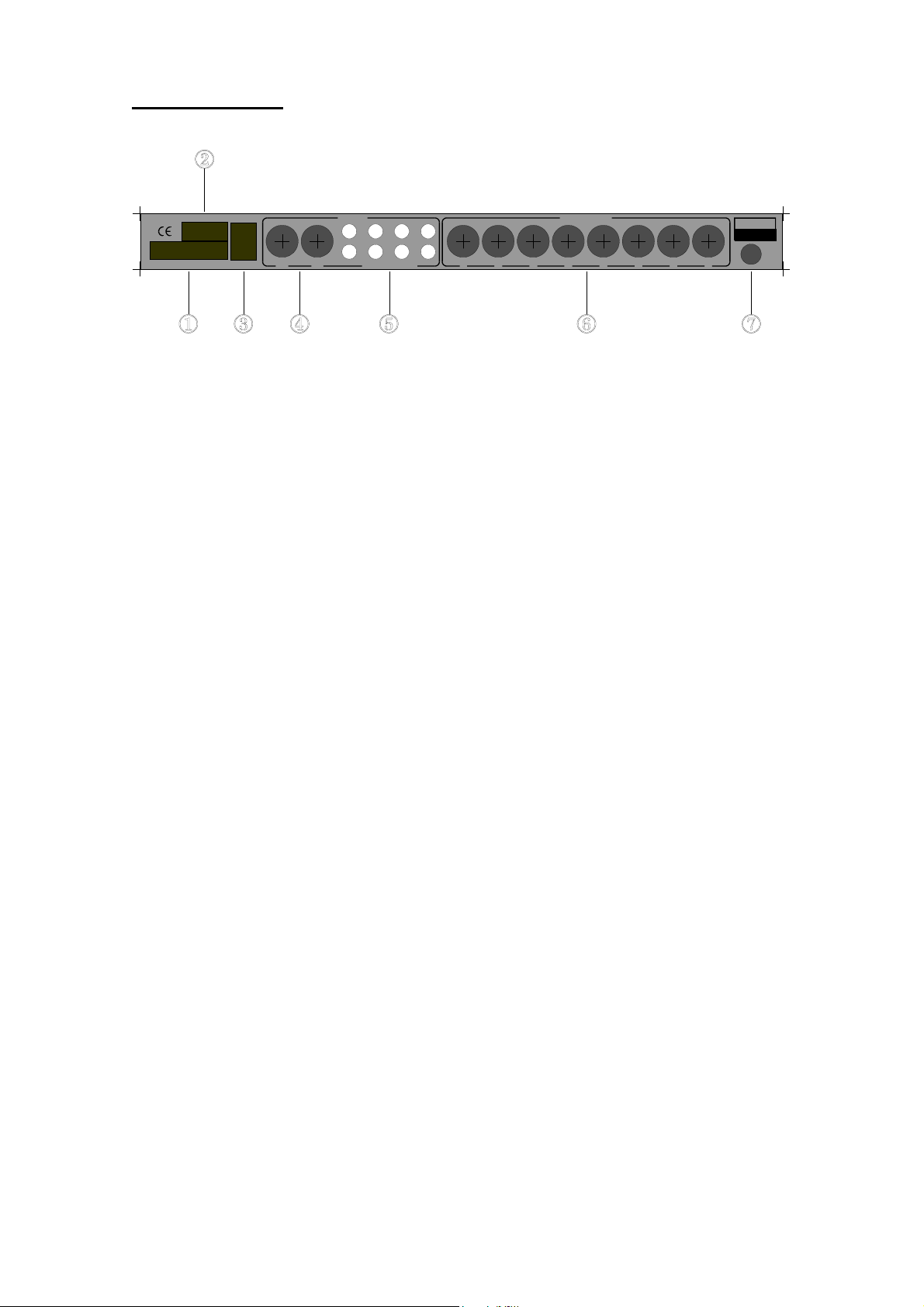
MR88 Rear Panel
CLOCKAUDIO
Made in EEC-UK
Link OutRS232
External Control Link In
A B
Outputs Input Channels
7 5 3 1
8 6 4 2
Pre-Amp Outputs 678 5 4 3 2 1
Input
1) External Control Connector. Provides access to the open-collector
outputs, the external control inputs, and the two VCA connections.
2) RS232 Connector. For control and setup of MR88 mixers. Control
extends through link connections to multiple mixers.
3) Link In/Out. Used for daisy chaining of multiple MR88 mixers when
more than 8 input channels are required. Uses standard RJ45 network
leads.
4) Balanced Outputs. The MR88 has two XLRM-type connectors with
individually or linked adjustable output gains to give nominal output
levels of -60 to 0dBV. This can be setup to be controlled by external
VCA’s for remote operation.
DC
5) Pre-Amp Outputs. Individual channel –10dBV outputs on RCA phono
connectors for tape recording pre-mix channels.
6) Source Inputs. XLRF-type connectors. Balanced inputs for low
impedance dynamic or condenser microphones, line inputs and audio
equipment (CD players etc). Input gain adjustable from front panel.
48V phantom power can be selected from front panel for microphones.
7) Power Input. External 15V power supply.
Page 6
Page 7

MR88 Menu Functions
Navigation through the menu system is via the CHANNEL (
FUNCTION (
↔
) buttons. The table below illustrates the structure of the
↔
) and
menu.
Output Ch 1 Ch 2 Ch 3 Ch 4 Ch 5 Ch 6 Ch 7 Ch 8 System
Channel
A+B Gain
Channel
A Gain
Channel
B Gain
Channel
A Source
Channel
B Source
Compress Compress Compress Compress Compress Compress Compress Compress Control
Mono /
Stereo
MicPhant/
Mic/Line
MONO
Gain
STEREO
Gain L+R
STEREO
Gain Left
STEREO
Gain Right
Mono /
Stereo
MicPhant/
Mic/Line
MONO
Gain
STEREO
Gain L+R
STEREO
Gain Left
STEREO
Gain Right
Mono /
Stereo
MicPhant/
Mic/Line
MONO
Gain
STEREO
Gain L+R
STEREO
Gain Left
STEREO
Gain Right
Mono /
Stereo
MicPhant/
Mic/Line
MONO
Gain
STEREO
Gain L+R
STEREO
Gain Left
STEREO
Gain Right
Mono /
Stereo
MicPhant/
Mic/Line
MONO
Gain
STEREO
Gain L+R
STEREO
Gain Left
STEREO
Gain Right
Mono /
Stereo
MicPhant/
Mic/Line
MONO
Gain
STEREO
Gain L+R
STEREO
Gain Left
STEREO
Gain Right
Mono /
Stereo
MicPhant/
Mic/Line
MONO
Gain
STEREO
Gain L+R
STEREO
Gain Left
STEREO
Gain Right
Mono /
Stereo
MicPhant/
Mic/Line
MONO
Gain
STEREO
Gain L+R
STEREO
Gain Left
STEREO
Gain Right
Priority 1
mode
Priority 2
mode
Priority 3
mode
Priority 4
mode
Last One
on
Code
Outputs
EQ Lo EQ Hi EQ Hi EQ Hi EQ Hi EQ Hi EQ Hi EQ Hi Control
Inputs
EQ Hi EQ Lo EQ Lo EQ Lo EQ Lo EQ Lo EQ Lo EQ Lo
Output to Output to Output to Output to Output to Output to Output to Output to
Priority Priority Priority Priority Priority Priority Priority Priority
Gate Off Gate Off Gate Off Gate Off Gate Off Gate Off Gate Off Gate Off
Detector Detector Detector Detector Detector Detector Detector Detector
Manual
Detect
Level
Hold time Hold time Hold time Hold time Hold time Hold time Hold time Hold time
NOMA NOMA NOMA NOMA NOMA NOMA NOMA NOMA
Manual
Detect
Level
Manual
Detect
Level
Manual
Detect
Level
Manual
Detect
Level
Manual
Detect
Level
Manual
Detect
Level
Manual
Detect
Level
VCA
Page 7
Page 8

Menu System
Output Ch 1 Ch 2 Ch 1 + 2 System
Gain Ch A+B
-60dB – 0dB
Gain Ch A
-60dB – 0dB
Gain Ch B
-60dB – 0dB
Source Ch A
Off/X/Y/
X+Y
Source Ch B
Off/X/Y/
X+Y
EQ Lo
Input Type
Mono/Stereo
Input Level
Mic + Phantom
/Mic/Line
Gain
-40dB - +20dB
Compression
Off/1 – 8/Max
-12dB - +12dB
Input Type
Mono/Stereo
Input Level
Mic + Phantom
/Mic/Line
Gain
-40dB - +20dB
Compression
Off/1 – 8/Max
EQ Lo
-12dB - +12dB
Input Type
Stereo/Mono
Input Level
Mic + Phantom
/Mic/Line
Gain
Left
-40dB - +20dB
Gain
Right
-40dB - +20dB
Gain
Left + Right
-40dB - +20dB
Compression
Off/1 – 8/Max
EQ Lo
-12dB - +12dB
Priority 1 mode
Inclusive/
Exclusive
Priority 2 mode
Inclusive/
Exclusive
Priority 3 mode
Inclusive/
Exclusive
Priority 4 mode
Inclusive/
Exclusive
Last Active
Channel
On / Off
Security Lock Code
0000 - 9999
change digit 1
Security Lock Code
0000 - 9999
change digit 2
EQ Hi
-12dB - +12dB
Output to
Off/BusX/BusY/
BusX+BusY
Priority
1 - 4
Gate Off Atten
6dB - 40dB
+ Mute
Detector Type
Auto speech/
Auto music/
Manual
Force On
Force Off
Manual Detector
-40dB to 0dB
EQ Hi
-12dB - +12dB
Output to
Off/BusX/BusY/
BusX+BusY
Priority
1 - 4
Gate Off Atten
6dB - 40dB
+ Mute
Detector Type
Auto speech/
Auto music/
Manual
Force On
Force Off
Manual Detector
-40dB to 0dB
EQ Hi
-12dB - +12dB
Output to
Off/BusX/BusY/
BusX+BusY/Stereo
Priority
1 - 4
Gate Off Atten
6dB - 40dB
+ Mute
Detector Type
Auto speech/
Auto music/
Manual
Force On
Force Off
Manual Detector
-40dB to 0dB
Security Lock Code
0000 - 9999
change digit 3
Security Lock Code
0000 - 9999
change digit 4
Control Outputs
High/
Low
Control Inputs
Force off /
Force on
VCA Control
VCA1 off VCA2 off
VCA1 ChA VCA2 off
VCA1 ChB VCA2 off
VCA1 ChA+B VCA2
off
VCA1 ChA VCA2
ChB
Hold time
50mS/100mS/
200mS/500mS
/1S / 2S
NOMA
On/Off
Hold time
50mS/100mS/
200mS/500mS
/1S / 2S
NOMA
On/Off
Hold time
50mS/100mS/
200mS/500mS
/1S / 2S
NOMA
On/Off
Page 8
Page 9

Changing Channels and Functions.
On power up, if the MR88 is not locked, the channel is set to Output A+B and
the function to Gain Channel A and B. Pressing the CHANNEL buttons move
forwards and backwards through Channels 1 to Channel 8, System and
Output A+B channels. The FUNCTION buttons move up or down through the
available functions for each channel.
Changing Values.
To change the values of each function, simply turn the Rotary Control to
display the desired value.
Page 9
Page 10

Explanation of Functions
Output A+B Functions:
Output ChA and ChB Gain. Linked control of the output channels A and B
nominal gain.
When the >Function button is pressed the ChA gain flashes to indicate
independent setting of the output channel A nominal output gain.
When the >Function button is pressed again the ChB gain flashes to indicate
independent setting of the output channel B nominal output gain.
When the >Function button is pressed again the Channel A source flashes
to indicate which common bus the local output A should use as its source.
This can be set for Off, Bus X, Bus Y or Bus X and Bus Y
When the >Function button is pressed again the Channel B source flashes
to indicate which common bus the local output B should use as its source.
This can be set for Off, Bus X, Bus Y or Bus X and Bus Y
Functions of Channels 1 – 8:
Mono/Stereo
The MR88 can be set so that Channels 1 & 2, 3 & 4, 5 & 6, or 7 & 8 are
considered as a stereo pair. This reduces the number or setups required for
a stereo music source. Each stereo pair has only one setting for Input Level,
compression, EQ, Output, priority, gate attenuation, detector and hold time.
Gain adjustments for the Left and Right Channels can be linked or
independently set.
Line/Mic/Phantom
This sets the nominal input level to mic level + 48V phantom power, mic level
without phantom power or line level.
Gain Control - Pre-Amplifier
The MR88 has a substantial gain range, (-40 to +20dB) allowing the use of a
variety of microphones and line inputs. Generally, if the level has been set to
the correct type in the previous menu, only small changes should be
necessary. The LED meter displays the individual selected input channel
level, and the headphone monitor can be used to listen to the channel, so
that the gain can be set per channel, even when the channel is not
connected to the output. When set to stereo three functions allow the gain
adjustments for the Left and Right Channels to be linked or independently
set.
Page 10
Page 11

Compression
The task of the compressor is to reduce the dynamic range of the input signal
and to control the overall level. The MR88 has a compressor on each of the
inputs that can be set to Off, 1 – 8 and Max. These settings vary from 1:1 to
6:1. These can be useful when dealing with large variations of speech input
level. On the highest setting even the quietest whisper can be heard at the
same volume as the loudest voice.
Equaliser
EQ Low. 12dB boost or cut of the low frequency components of the audio
signal with this, 200 Hz fixed frequency, shelving filter. This is useful for
adding warmth to a microphone or subtracting boom.
EQ High. 12dB boost or cut of the high frequency components of the audio
signal with this, 5kHz fixed frequency, shelving filter. This can be useful for
boosting dull sounding microphones, or reducing the sibilance of lively
microphones.
Output - Selection
Output. Selects if a channel is not used (Off) or goes to Output Bus X,
Output Bus Y, or Output Bus X + Y of the mixer. A pair set to stereo, are
treated in almost exactly the same way. When set to Output Bus X, the pair is
placed as mono onto output bus X. When set to Output Bus Y, the pair is
placed as mono onto the Output Bus Y. When set to Output Bus X+Y, the
pair is placed as mono onto the Output Bus X and as mono onto the Output
Bus Y. When set to Stereo output, the lower input channel number of the pair
is placed on Output Bus X and the higher input channel number to Output
Bus Y. When the output is set to OFF the channel is removed from detection
and priority. Because the monitor for a channel is active whenever the
channel is selected, setting the input channel parameters on a live system
without affecting the output is possible.
Priority Select Function
The priority of each microphone channel can be selected using this function.
Each can be set from 1 to 4. Channels set to the higher priority override
channels with a lower priority. The mode of operation for channels with the
same priority can be set in the system menu. This can be inclusive or
exclusive.
Microphones that are locked out or overridden are attenuated. The level of
attenuation can be adjusted using the gating level control for each channel.
Gating – Off Attenuation Level Control
Sets the level of 'off' attenuation (6dB - 40dB or muted) for each channel.
When the number of microphones in use is high it may be necessary to
increase the amount of "off" attenuation per microphone, to keep the total
ambient noise level low.
Page 11
Page 12

Detector - Adjustable Detector Control
Detector. The MR88 gives comprehensive control over channel detection.
Channels are connected to the output, dependant on priority setting, when a
signal is detected. The method used for detection can be selected by type of
input. These are Auto Speech, Auto Music, Manual Level Set, Detector
Forced On, and Detector Forced Off.
Auto Speech detector is an adaptive threshold and is very useful in noisy
environments, as the microphone will only trigger 6dB above the background
noise.
Auto Music Detector is designed to detect music.
Manual Detector Level setting can be set so that the channel triggers on a
specific level of sound (-40dB to - 0dB).
Detector Forced On is used to make the selected channel appear triggered
even when no sound is present. This can be useful for setting a particular
microphone to be the ambient microphone of a system rather that use the
“last one on” function, or used in conjunction with external control as a
manual mixer.
Detector Forced Off is used to make the selected channel never trigger on
sound. It can be used in conjunction with external control as a manual mixer.
Hold - Time
Hold time is the time a microphone channel is below trigger level before it
releases the lockout bus. The Hold time is adjustable with 5 settings.
50mS, 200mS, 500mS, 1 Second, 2 Seconds. The fastest setting will allow
microphones to switch on the slightest break in the speech. Sometimes it is
desirable to extend this time. E.g. Voice over music applications might need
the longest hold period.
NOMA (Number of Open Microphones Attenuated) Control
The NOMA system helps reduce feedback, by allowing for the increase in
system gain, as the number of open microphones increases. When selected,
the MR88 identifies exactly how many NOMA selected microphones are on,
and automatically adjusts the gain. However, NOMA will reduce the sound
level of each individual person speaking, which may not be desired,
especially in applications such as conferencing. By selecting this function
individually for each channel the system designer can control which
microphones are included in the NOMA calculation.
Page 12
Page 13

System Functions:
Priority
There are 4 levels of priority for the channels. Each priority can be assigned
one of two modes: Priority 1 is the lowest, priority 4 the highest. Channels of
a higher priority will lock out channels of a lower priority.
• Inclusive mode. - All microphones that are allowed to be active are
• Exclusive mode - "First-come-first-served" mode. Only one microphone
Last Active Channel
This feature enables the last microphone channel used to be left switched on
until a new channel is detected. This can help to keep a constant ambient
sound in a system. If used in a multiple mixer linked system all mixers need
to have this system option set.
mixed to the selected output bus.
can be on at any one time. All other microphone
channels of the same priority are locked out until the
controlling microphone goes silent. Switching between
microphone channels can be controlled from very fast,
to up to 2 seconds, depending upon application.
Security Code
The 4 digit code displayed is the current security code. This can be changed
by simply turning the Rotary Control to change each digit and by pressing the
FUNCTION buttons to select the digits.
Page 13
Page 14
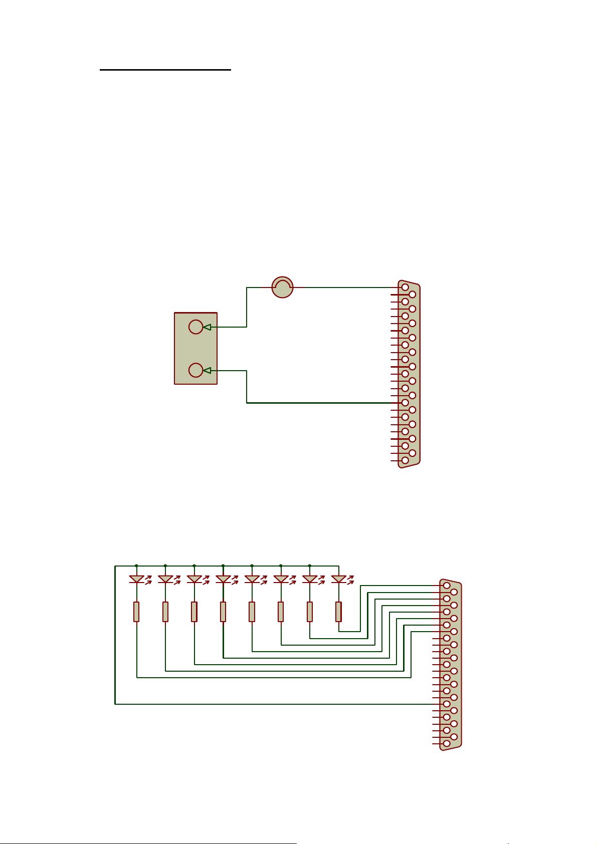
Active Control Outputs
The MR88 has 8 open-collector outputs, one per microphone channel. These
can be used for external control for activating cameras, lights etc. upon
detecting speech. The open-collector outputs can sink 500mA each with a
maximum collector voltage of +50V DC. This allows a variety of external
devices to be driven from the mixer.
For extra flexibility the MR88 can be set so that these outputs are either
HIGH or LOW when the channel is active.
Examples
1. Externally powered lamps can be wired as follows:-
Lamp
+
+0 - 50V
PSU
-
Max 500mA
1
14
2
15
3
16
4
17
5
18
6
19
7
20
8
21
9
22
10
23
11
24
12
25
13
Control Port
Control Out 1
Control Out 2
Control Out 3
Control Out 4
Control Out 5
Control Out 6
Control Out 7
Control Out 8
Control In 8
Control In 7
Control In 6
Control In 5
Control In 4
Control In 3
Control In 2
Control In 1
Gnd
Gnd
+5V
VCA1 Top
VCA1 Wiper
VCA1 Gnd
VCA2 Top
VCA2 Wiper
VCA2 Gnd
2. High efficiency LED’s can be powered from the auxiliary 5V (pin 10) on the
control port. The maximum current allowed from this pin is 100mA.
LED LEDLEDLEDLEDLEDLEDLED
R8
470R
R7
470R
R6
470R
R5
470R
R4
470R
R3
470R
R2
470R
R1
470R
1
14
2
15
3
16
4
17
5
18
6
19
7
20
8
21
9
22
10
23
11
24
12
25
13
Control Port
Control Out 1
Control Out 2
Control Out 3
Control Out 4
Control Out 5
Control Out 6
Control Out 7
Control Out 8
Control In 8
Control In 7
Control In 6
Control In 5
Control In 4
Control In 3
Control In 2
Control In 1
Gnd
Gnd
+5V
VCA1 Top
VCA1 Wiper
VCA1 Gnd
VCA2 Top
VCA2 Wiper
VCA2 Gnd
Page 14
Page 15
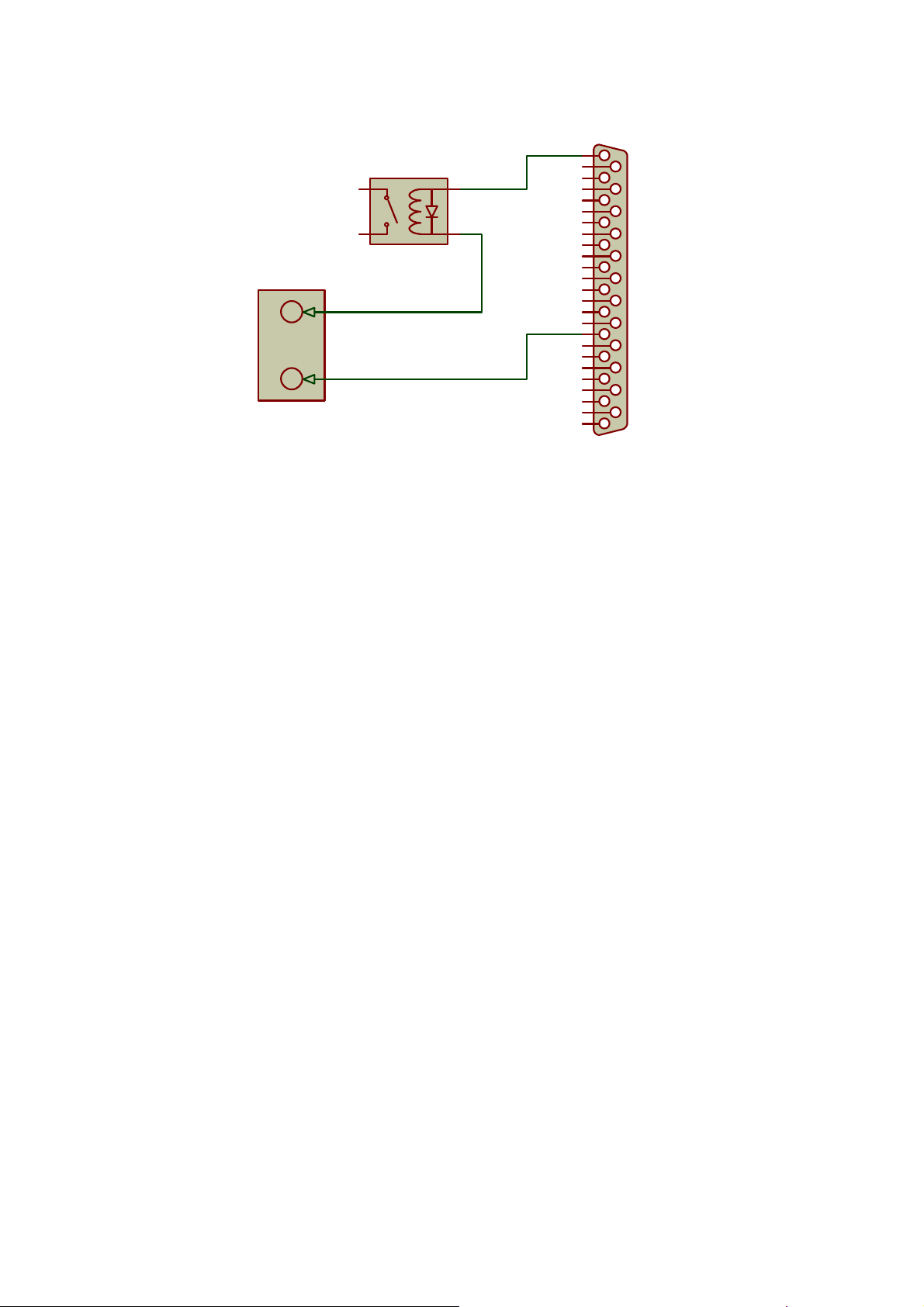
3. Relays can be wired as follows:-
+
24V PSU
-
4
1
24V Relay
1
14
2
3
2
15
3
16
4
17
5
18
6
19
7
20
8
21
9
22
10
23
11
24
12
25
13
Control Port
Control Out 1
Control Out 2
Control Out 3
Control Out 4
Control Out 5
Control Out 6
Control Out 7
Control Out 8
Control In 8
Control In 7
Control In 6
Control In 5
Control In 4
Control In 3
Control In 2
Control In 1
Gnd
Gnd
+5V
VCA1 Top
VCA1 Wiper
VCA1 Gnd
VCA2 Top
VCA2 Wiper
VCA2 Gnd
Page 15
Page 16
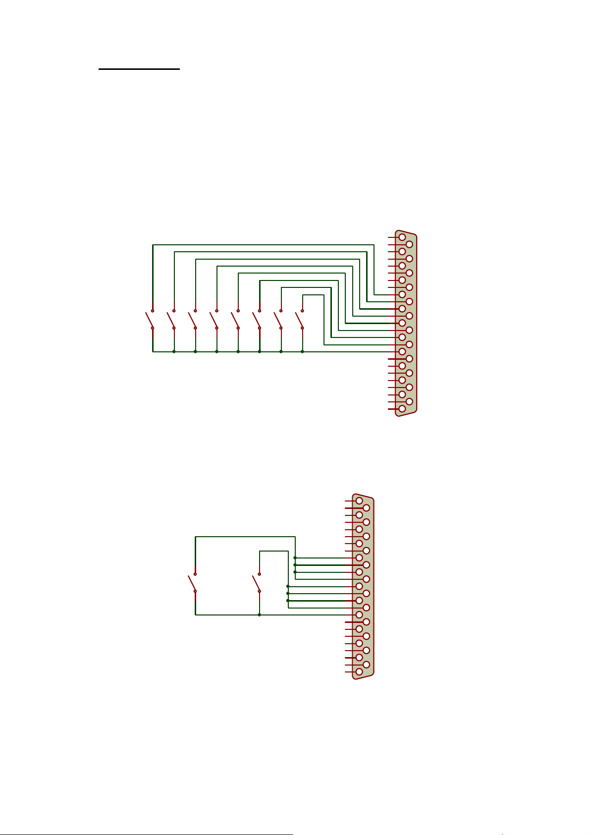
Control Inputs
Each channel has a force closure input to 0V.
This menu sets the sense of the closure switch. Force Off means that a
shorting switch would force a channel off. Force On means that a shorting
switch would have to be closed to allow a channel to be active.
Any channel can only become active if the detector and priority allow it to.
External wiring for switches to control the channels is as follows
1
14
2
15
3
16
4
17
5
18
6
19
7
20
8
21
9
22
10
23
11
Channel 1
Channel 2
Channel 3
Channel 4
Channel 5
Channel 6
Channel 7
Channel 8
24
12
25
13
Control Port
Control Out 1
Control Out 2
Control Out 3
Control Out 4
Control Out 5
Control Out 6
Control Out 7
Control Out 8
Control In 8
Control In 7
Control In 6
Control In 5
Control In 4
Control In 3
Control In 2
Control In 1
Gnd
Gnd
+5V
VCA1 Top
VCA1 Wiper
VCA1 Gnd
VCA2 Top
VCA2 Wiper
VCA2 Gnd
To control multiple channels on one switch, connect as follows:-
1
14
2
15
3
16
4
17
5
18
6
19
7
20
8
Mute Channels 5 - 8
Mute Channels 1 - 4
21
9
22
10
23
11
24
12
25
13
Control Port
Control Out 1
Control Out 2
Control Out 3
Control Out 4
Control Out 5
Control Out 6
Control Out 7
Control Out 8
Control In 8
Control In 7
Control In 6
Control In 5
Control In 4
Control In 3
Control In 2
Control In 1
Gnd
Gnd
+5V
VCA1 Top
VCA1 Wiper
VCA1 Gnd
VCA2 Top
VCA2 Wiper
VCA2 Gnd
Page 16
Page 17
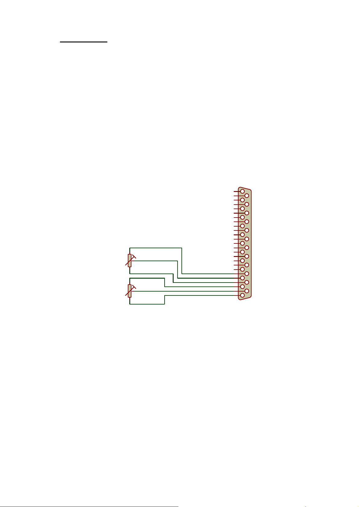
VCA - Control
Output Gain can be controlled by the external VCA’s connected to the
External Control Port. External potentiometers of 10k linear are required.
These will provide 0 to 60 dB of attenuation from the output gain setting in
the Output Gain menu.
These can be set for the following : VCA1 OFF VCA2 OFF
VCA1 Channel A VCA2 OFF
VCA1 Channel B VCA2 OFF
VCA1 Channel A and B VCA2 OFF
VCA1 Channel A VCA2 Channel B
Connection to the external control port is as follows:-
VCA1
10k Potentiometer
VCA2
10k Potentiometer
1
14
2
15
3
16
4
17
5
18
6
19
7
20
8
21
9
22
10
23
11
24
12
25
13
Control Port
Control Out 1
Control Out 2
Control Out 3
Control Out 4
Control Out 5
Control Out 6
Control Out 7
Control Out 8
Control In 8
Control In 7
Control In 6
Control In 5
Control In 4
Control In 3
Control In 2
Control In 1
Gnd
Gnd
+5V
VCA1 Top
VCA1 Wiper
VCA1 Gnd
VCA2 Top
VCA2 Wiper
VCA2 Gnd
Page 17
Page 18

External Control Port
Pin Number Function
1 Control Out 1
2 Control Out 3
3 Control Out 5
4 Control Out 7
5 Control In 8
6 Control In 6
7 Control In 4
8 Control In 2
9 Gnd (Chassis)
10 +5V Output ( 100mA Max )
11 VCA 1 Wiper
12 VCA 2 Top
13 VCA 2 Gnd (Chassis)
14 Control Out 2
15 Control Out 4
16 Control Out 6
17 Control Out 8
18 Control In 7
19 Control In 5
20 Control In 3
21 Control In 1
22 Gnd (Chassis)
23 VCA 1 Top
24 VCA 1 Gnd (Chassis)
25 VCA 2 Wiper
Page 18
Page 19

Link In/Out - Daisy Chain Capability
When more than eight microphones are needed, the MR88 can be daisy
chained via the Link In/Out connectors, with other MR88 mixers. This will
create a multi-mixer system with audio and control passing throughout the
system. All audio and control data is carried by link cables, from 8 pin RJ45
connectors at the rear of the mixer. (This is a 1 to 1 link ) This must be a
screened CAT 5E cable. (STP)
Each additional mixer contains the audio from the one previous and mixes its
outputs onto the output busses. This total mix is fed back up the chain from
the last mixer making the full mixed output available from any of the mixers in
the chain. Priority and control extends throughout the entire chain. The
practical limit of the number of MR88 mixers that can be daisy chained is 50.
The SYSTEM settings for Priority and Last One On should be set to be the
same for all mixers in the chain. If they are set up differently their operation
might be confusing.
RS232 Control
A PC program is available to setup the MR88 without the use of the front
panel. In a multi mixer system the RS232 can be plugged into any of the
mixers in the system, and the mixer to be set up selected from the program.
The MR88’s are automatically addressed from 1 to n when they are linked
together.
Page 19
Page 20

Installation
1. If rack mounting, fit the mixer to the rack before commencing with the
2. Connect 15 V DC power supply provided to the 2.1mm DC connector on
3. Turn the mixer on using the Power switch on the front panel.
Basic Set-up for Microphones
1. Connect a microphone to any input channel.
2. Using the CHANNEL button select the appropriate channel.
3. Use headphones in the Monitor Socket.
4. Select Mono or Stereo.
5. Select Level as appropriate. Microphone or Microphone + Phantom
rest of the set-up.
the rear panel.
power as required.
6. Adjust the Gain so that the Level Indicator peaks at 0dB when speaking
loudly into the microphone.
7. Adjust Compression to get the quietest sounds to the required level.
8. Adjust the EQ Low and EQ High for the required tonal quality.
9. Select Output to Bus X, Bus Y or Both Busses as required.
10. Select Priority as required.
11. Set the Gate Attenuation (Off Attenuation) to the level that is required
when the microphone is not active. This can be set to between 6dB and
40dB and completely muted.
12. Set the Detector Type to Auto speech detection.
13. Set the Hold time setting required 50mS, 100mS, 200mS, 500mS,
1 second and 2 seconds.
14. Decide if the channel should be included in the NOMA calculation.
15. Connect any further microphones to the remaining input channels and
carry out stages 2 to 13.
16. Select the Output A+B Channels and select the source for the output
channel A and Channel B.
17. Select the Output A+B Channel Gain and adjust the ChA and ChB output
levels to the required nominal level. Typical levels for microphone use
are –40dBV and for line levels 0dBV or –10dBV. The channel A and
channel B gain controls can be either set together or individually.
Page 20
Page 21

Security Mode
To ensure the mixer setting are not accidentally altered or deliberately
tampered with, the mixer has an adjustable 4-digit security code. When the
mixer is "Locked", the only way to "Unlock" it is to re-enter the security code.
Even if the mixer is switched off and on again, the mixer will re-enter locked
mode and still require the security code to be entered.
How to Change the Security Code:
In the System menu press the function button until the unlock code is
displayed. Use the rotary control and Function Buttons to set the code to the
desired value. The default factory code is 1234.
How to Lock the Mixer:
To lock the Mixer front panel settings hold down both the <CHANNEL and
>FUNCTION buttons for 3 seconds. A warning message will be displayed
that the mixer is about to be locked during this 3 seconds. Releasing the keys
will abort the locking process. After the 3 seconds the mixer will display
"Mixer Locked."
How to Unlock the Mixer:
When the mixer is locked it will either display "Locked, Enter Code ----", or
"Clockaudio MR88". To unlock the front panel controls, press either the
CHANNEL or FUNCTION buttons. Enter the correct code using the rotary
control and Function Buttons and press either the CHANNEL or FUNCTION
buttons to unlock the mixer.
Lost Security Code:
If the security code is lost or forgotten the mixer can be reset to factory
defaults by switching on the mixer with the >CHANNEL and <FUNCTION
buttons held down. This will restore the security code to 1234 and unlock the
mixer. All other settings are also reset, so a full setup procedure must be
carried out.
Page 21
Page 22

Specifications
Input Impedance
Output Impedance
Balanced
Pre-Amp Out
Max Input Level
Mic Level -23 dBV
Line Level +16 dBV
Max Output Level +19 dBV
Nominal Output Level
at 0 dB on Meter
Pre-amp Out -10 dBV
Balanced -60 dBV to +4 dBV (Level set on front panel)
Frequency Response 20Hz to 20kHz
THD+N -70 dB
Max NOMA Attenuation 20 dB
2.4kΩ Differential
50Ω
560Ω
Phantom Power +48V
Power Supply 15Vdc 3.4A External Power Supply with
2.1mm connector.
Notes:- +ve connected to centre pin
–ve is connected to chassis ground
internally
Operating Temperature
Dimensions W483mm x D215mm x H44mm
Weight 2.2kg approx
0° to 40°C
Page 22
 Loading...