

Page 1
Clockaudio
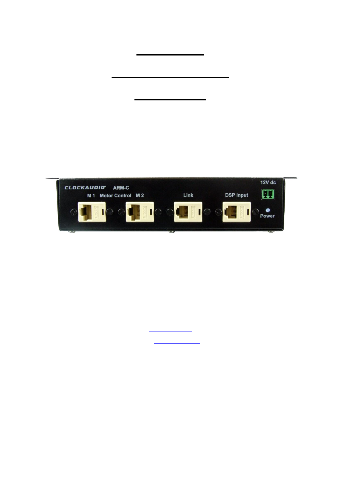
ARM-C Control Box
Instructions
www.clockaudio.com
email: [email protected]
Clockaudio Ltd 22 Arnside Road Waterlooville Hampshire PO7 7UP England
1
Page 2

Product Guarantee
Thank you for purchasing a Clockaudio product. We are confident that this product will give you many
years of trouble free operation and is backed up with a 2 year guarantee.
Important: Guided Tour systems, Mixers and RF products must have the guarantee activated by
completing the registration details on Clockaudio web site. Look for the warranty tab under the
Technical Library. Clockaudio will retain the details on their database for future reference.
This product is guaranteed for 24 months from the date of purchase. Any defect that arises due to
faulty materials or workmanship will either be replaced, or repaired free of charge by the agent from
whom you purchased the unit. Please note charges will be incurred on any products returned for
service / repair not in warranty or has been subject to customer abuse or incorrect wiring.
The guarantee is subject to the following provisions:
The guarantee does not cover accidental damage, misuse, cabinet parts, knobs, batteries or
consumable items. Any product returned to Clockaudio failing to meet the terms listed will
incur a repair and postage charge.
The product must be correctly installed and operated in accordance with the instructions
supplied with the product.
Unauthorised modifications and alterations to the original specifications will render the
guarantee void
The product must be used for the sole purpose that it was designed for.
The guarantee given is strictly with the original owner and becomes invalid if the product is
resold or becomes damaged by inexpert repair.
Product purchased outside of the countries served by Clockaudio designated / approved
Agents are not covered by the warranty.
Specifications / improvements are subject to change without notice.
Clockaudio disclaims any liability for incidental or consequential damages.
The guarantee is in addition to and does not diminish your statutory legal rights.
For more information and advice on Clockaudio products please look on Clockaudio website:
www.clockaudio.com
Tel: +44 (0) 23 9225 1193 Fax: +44 (0) 23 9225 1201
Email: [email protected]
Clockaudio Ltd 22 Arnside Road, Waterlooville, Hampshire, PO7 7UP England
2
Page 3
ARM Control Box Overview
Warning: Under no circumstances must any equipment be
connected to the M1 – M4 motor power outlet sockets of
the ARM controller box. Serious damage to equipment
and control box will occur which is not covered under the
guarantee given.
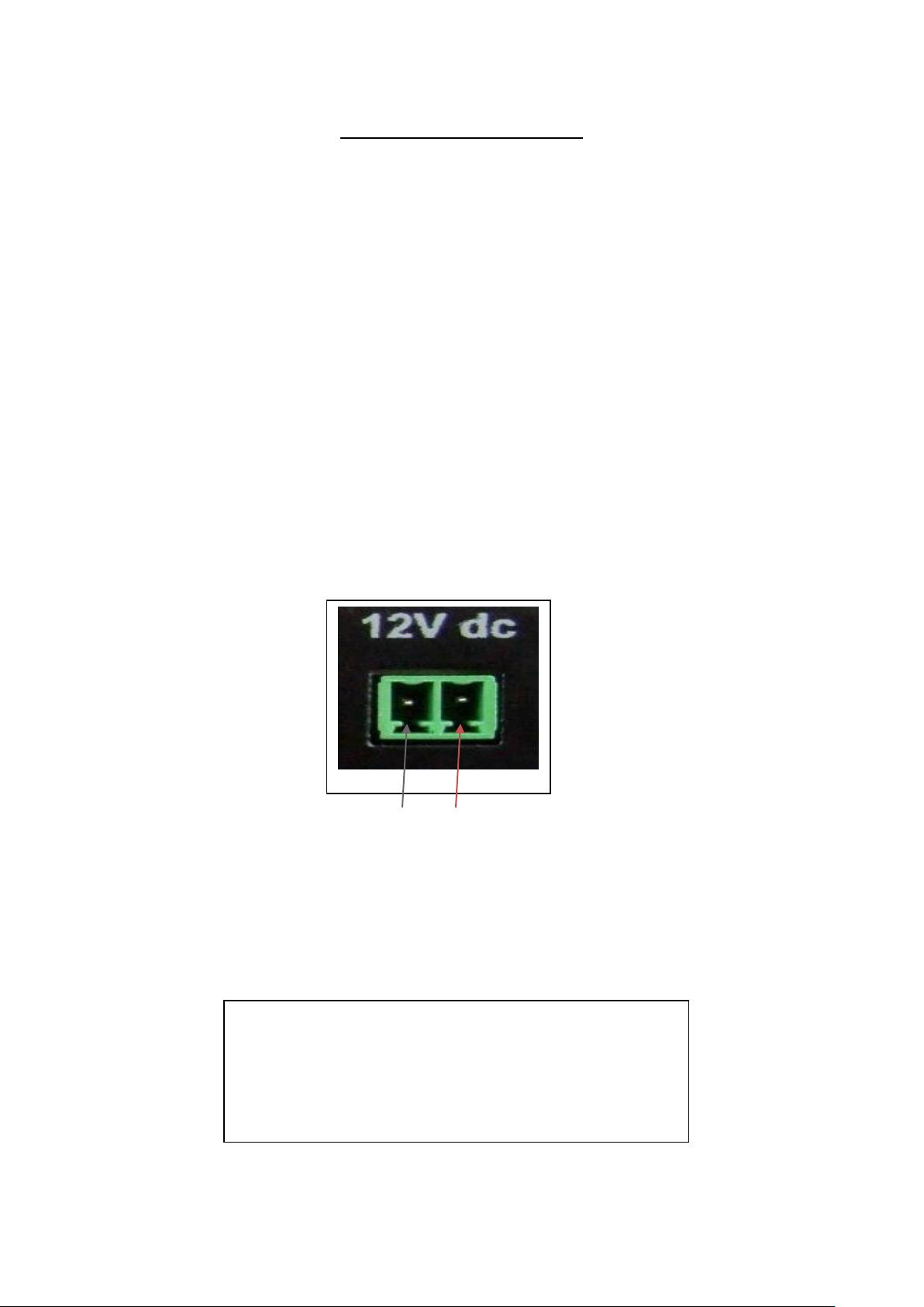
Link / DSP (2 x RJ12) control ports allow DSP connection and Link / daisy
chain expansion to other control boxes. A single command from a DSP will
simultaneously activate all connected ARM motorised microphones.
Logic input connections to the Link / DSP control ports pin 2 live and 1 Gnd.
A positive (+2.5V to +12V) signal applied to the DSP control port will
simultaneously activate all ARM motorised microphones connected to the
control box M1 – M4 RJ45 motor outlet ports.
M1 – M4 ports allows for fast and easy connection of 4 x ARM motorized
microphones.
Removable Pheonix connector for the connection of an external 12V DC 2A
supply (ARM-PSU 1).
_ +
Led power indicator.
Simple screw fixing of box.
3
Page 4
Connections
1. Install the ARM motorised microphone as per separate instructions given with
the product.
2. Ensure that the Control box power supply is NOT switched on until all wiring
and connections have been completed.
3. Connect the ARM motorised microphone plug/s to any of the M1 – M4 motor
outlet ports on the Control box. It does not matter which port is used as they
are connected in parallel.
4. Connect the DSP logic signal output terminals to the DSP input socket on the
Controller box. Use the Link port to connect to other Control boxes.
5. Connect the microphone audio output cable to your mixer / DSP.
6. Power up the DSP and check that the programming has been set for use on
the ARM using +2.5V to +12V logic high to raise the microphone. The
microphone should be muted whilst in the upward or downward transition to
prevent unwanted motor noise pickup.
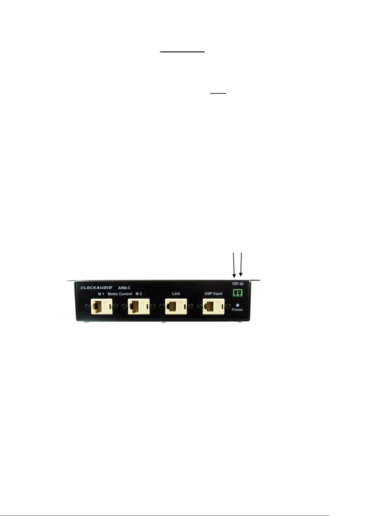
7. Connect the 12V DC power supply to the DC +/- input terminals of the
Controller box observing the correct polarity - +
8. Turn on the DC supply to the controller box. The coloured power indicator will
illuminate confirming that a supply is present. The motorised microphone may
initially very slowly fully extend and then retract. This is normal as it will be
auto-calibrating.
9. When a logic high is received from a DSP, the microphone will raise and
remain raised until a logic low is received.
4
Page 5
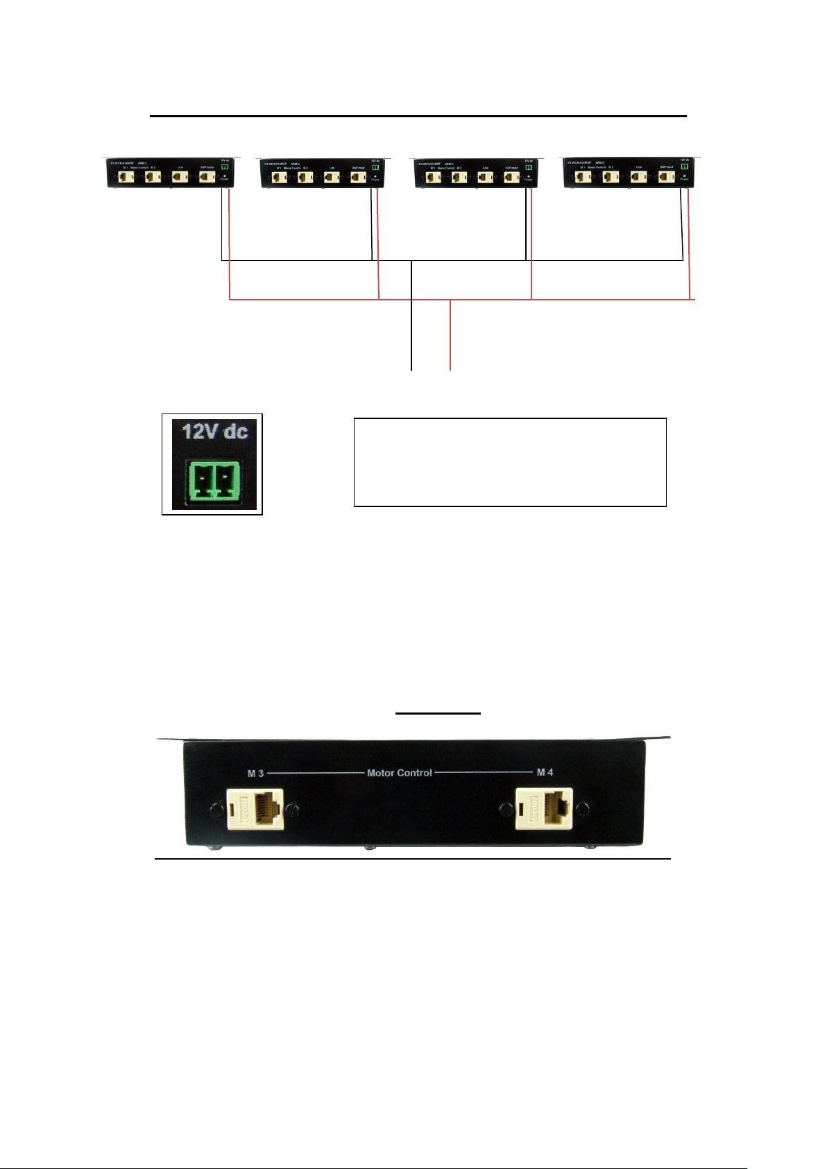
CONNECTING 4 X ARMC CONTROL BOXES USING SINGLE AC ADAPTOR
Negative - Positive + DC Input from AC adaptor:
Ensure
correct
polarity
-/+
Connecting 4 ARM-C using single high
power AC adaptor (ARM-PSU 4).
Connection / termination blocks (not
supplied) will be required.
Rear panel
5
Page 6
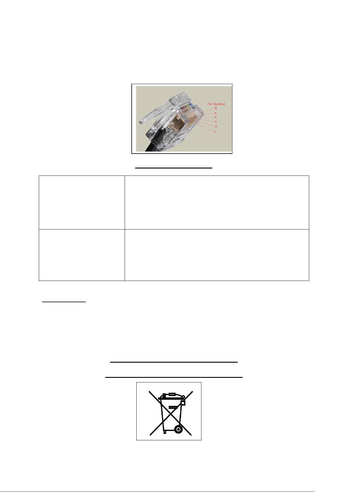
If the RJ12 cables need to be lengthened readymade / off the shelf extension
Microphone does not move
up or down
Check that the DSP control signal is present logic +2.5
to 12 Volts is required.
Is the microphone motor cable connected?
Is the DC supply to the Controller box switched on blue
power light should be illuminating?
Check logic input cable connections between DSP
and DSP control ports on the controller box.
Microphone is picking up
noise as it is being raised /
lowered.
This is normal. The microphone must be muted by the
DSP during the raising / lowering transitions.
cables are freely available at your high street electrical retail outlet. If cables
are to be handmade then connections are made to pins 2 (Live) & 1 (Ground)
shown below all other pins are not used.
Troubleshooting Guide
Specifications
Power supply requirements per control box: ARM-PSU 1
Motor activation / trigger input logic level +2.5 to +12V
Dimensions W 198 H 42 D 85mm
At the end of the life of this equipment
Dispose of according to local regulations
Sm15042012
6
 Loading...