


Installation and Maintenance Instructions
Dual Gas Steam Generator & Convection Steamer
24CGA10.2
24CGA6.2
Series: Gemini Model Nos. 24CGA6.2, 24CGA10.2
1333 East 179th Street
Cleveland, Ohio 44110
Phone: (216) 481-4900
Fax: (216) 481 3782
Part No. GEMINI-INM B 7/02
FOR THE INSTALLER
FOR YOUR SAFETY
Do not store or use gasoline or other flammable vapors or liquids in the vicinity of this or any other appliance.
 WARNING
Disconnect power before servicing
 WARNING
Improper installation, adjustment, alterations, service or maintenance can cause property damage, injury or death. Read the installation, operating and maintenance instructions thoroughly before installing or servicing this equipment.
IMPORTANT
IT IS IMPORTANT TO POST INSTRUCTIONS WHICH ARE TO BE FOLLOWED
IN THE EVENT THE USER SMELLS GAS. THESE INSTRUCTIONS SHOULD BE LOCATED IN A PROMINENT LOCATION, AND BE FULLY UNDERSTOOD BY ALL USERS OF THIS EQUIPMENT. THIS INFORMATION SHOULD BE OBTAINED FROM YOUR LOCAL GAS SUPPLIER.
ALL SERVICE MUST BE PERFORMED BY A QUALIFIED CLEVELAND RANGE AUTHORIZED TECHNICIAN.
The wiring diagram is located on the back of the lower front panel.
RETAIN THIS MANUAL FOR YOUR REFERENCE
INSTALLATION AND MAINTENANCE
Gemini Dual Gas Steam Generator and Convection Steamer
|
|
|
|
|
|
|
|
Table of Contents |
|
|
|
Chapter |
|
|
|
|
|
|
Page |
||
CHAPTER 1 PRODUCT IDENTIFICATION ________________________________________ |
1 |
|||||||||
A. MODEL NUMBER |
________________________________________________________ |
1 |
||||||||
B. |
SERIAL NUMBER |
________________________________________________________ |
1 |
|||||||
C. |
PRODUCT INFORMATION PLATE |
__________________________________________ |
1 |
|||||||
D. |
24CGA6.2 PRODUCT VIEW |
_______________________________________________ |
2 |
|||||||
E. |
24CGA10.2 PRODUCT VIEW |
_______________________________________________ |
3 |
|||||||
CHAPTER 2 INSTALLATION INSTRUCTIONS _____________________________________ |
4 |
|||||||||
A. |
GENERAL ______________________________________________________________ |
4 |
||||||||
B. INSTALLATION OF THE STEAMER |
_________________________________________ |
4 |
||||||||
|
1. |
Locating the Steamer |
__________________________________________________ |
5 |
||||||
|
|
a. |
Location and Clearance Requirements of the Steamer |
_____________________ |
5 |
|||||
|
|
b. |
Exhaust Hood Requirements |
_________________________________________ |
8 |
|||||
|
|
c. |
Positioning and Leveling the Steamer __________________________________ |
8 |
||||||
|
2. |
Install Slide Racks _____________________________________________________ |
8 |
|||||||
|
3. |
Install the Free Air Vented Drain Lines _____________________________________ |
9 |
|||||||
|
4. |
Install Gas Supply Lines ________________________________________________ |
10 |
|||||||
|
|
a. |
Gas Supply Requirements |
___________________________________________ |
10 |
|||||
|
|
b. |
Install Gas Supply Lines |
____________________________________________ |
10 |
|||||
|
|
c. |
Testing Gas Supply Lines |
___________________________________________ |
11 |
|||||
|
5. |
Install Electric Power Lines |
_____________________________________________ |
11 |
||||||
|
6. |
Water Supply Requirements and Installation ________________________________ |
12 |
|||||||
|
|
a. |
Water Supply Requirements |
_________________________________________ |
12 |
|||||
|
|
b. |
Setting the Descale Required Light ____________________________________ |
13 |
||||||
|
|
c. |
Install Water Supply Lines |
___________________________________________ |
15 |
|||||
|
|
d. |
Testing Water Supply Lines |
__________________________________________ |
16 |
|||||
C. STARTUP AND CHECKOUT |
_______________________________________________ |
16 |
||||||||
|
1. |
Installation Checkout |
__________________________________________________ |
17 |
||||||
|
2. |
Burner Ignition Test (Lighting and Shutdown Instructions) |
______________________ |
18 |
||||||
|
|
a. |
Lighting Instructions ________________________________________________ |
18 |
||||||
|
|
b. |
Shutdown Instructions |
______________________________________________ |
19 |
|||||
|
3. |
Start Up Test Procedure Gas Gemini ______________________________________ |
19 |
|||||||
|
|
a. |
Startup Procedure __________________________________________________ |
20 |
||||||
|
|
b. |
Blowdown Inspection |
_______________________________________________ |
20 |
|||||
|
|
c. |
Operating Tests and Final Checkout Procedure __________________________ |
21 |
||||||
CHAPTER 3 PREVENTATIVE MAINTENANCE AND TROUBLESHOOTING ____________ |
23 |
|||||||||
A. |
MAINTENANCE |
_________________________________________________________ |
23 |
|||||||
|
1. |
Maintenance Records |
__________________________________________________ |
23 |
||||||
|
2. |
Yearly Maintenance |
___________________________________________________ |
24 |
||||||
B. TROUBLESHOOTING GUIDE |
______________________________________________ |
24 |
||||||||
CHAPTER 1 PRODUCT IDENTIFICATION
Cleveland Range, Inc. assigns two product identification numbers to each steamer: a model number and a serial number. The model number identifies the product characteristics. The serial number identifies the individual unit.
A. MODEL NUMBER
This manual covers the Gemini Model No. 24CGA6.2 and 24CGA10.2 Dual Steam Generator and Convection Steamer.
Each character of this model number identifies a characteristic of the steamer. The Gemini Model No. 24CGA10.2 is 24 inches wide, a Convection steamer, Gas powered, and an Atmospheric steam generator with a capacity for 10 cooking pans, this model has the extra suffix “.2” to differentiate it from our standard 10 pan model that does not have two separate generators. This manual covers all standard features and options available on Gemini gas steamers.
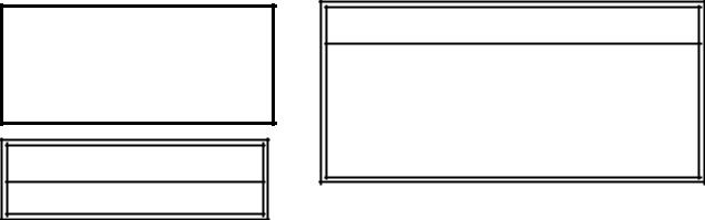
Other than selection of options, there are presently no significant design, parts, or operating differences among steamers with this model number. Figures 1-2 and 1-3 illustrate the two Gemini designs of gas fired steamers and identifies their major components.
B. SERIAL NUMBER
During manufacture, Gemini Steamers are assigned individual serial numbers. Whenever any inquiry is made with Cleveland Range regarding a steamer the serial number should be referenced.
C. PRODUCT INFORMATION PLATE
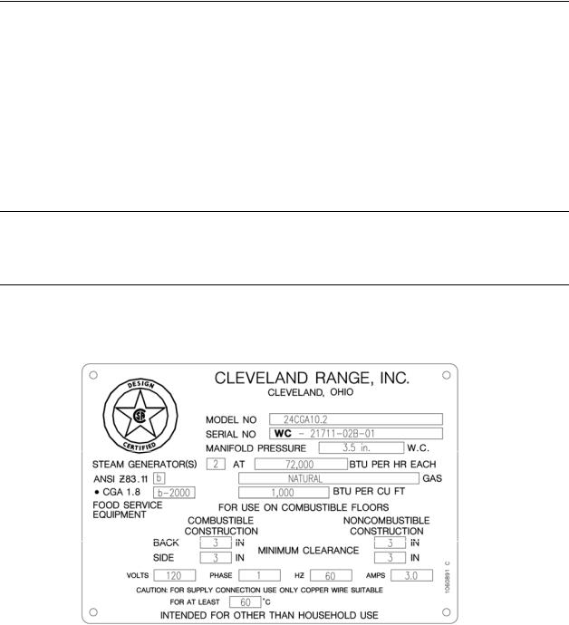
The Product Information Plate on the left side of the unit lists the model and serial number of the steamer. Refer to Figures 1-2 and 1-3 for the location of the plate. Figure 1-1 illustrates a typical Gemini Product Information Plate. The rating plate also lists power and wiring requirements.
Figure 1-1 Gemini Product Information Plates
1

D. 24CGA6.2 PRODUCT VIEW
PRODUCT INFO. PLATE ON LEFT ACCESS PANEL
FLUE OUTLET
WATER LEVEL PROBE HOUSINGS
LEFTLOWER COMPARTMENT
RIGHTUPPER COMPARTMENT
DESCALING
PORTS
AIR VENTS
RIGHT SIDE
SERVICE
PANEL
CONTROL PANEL (UPPER)
CONTROL PANEL (LOWER)
POWER ON/OFF |
RIGHT SIDE |
CONTROLS |
SERVICE PANEL |
DRIP TRAY |
|
WIRING DIAGRAMS ARE |
|
LOCATED ON THE BACK OF |
|
FRONT ACCESS PANEL |
NOTE: NOT ALL DETAILS ARE SHOWN |
|
MAIN |
FRONT ACCESS PANEL |
CONTROL |
DRAWER |
Figure 1-2. Gemini 6-Pan Dual Atmospheric Steam Generator
and Convection Steamer
2
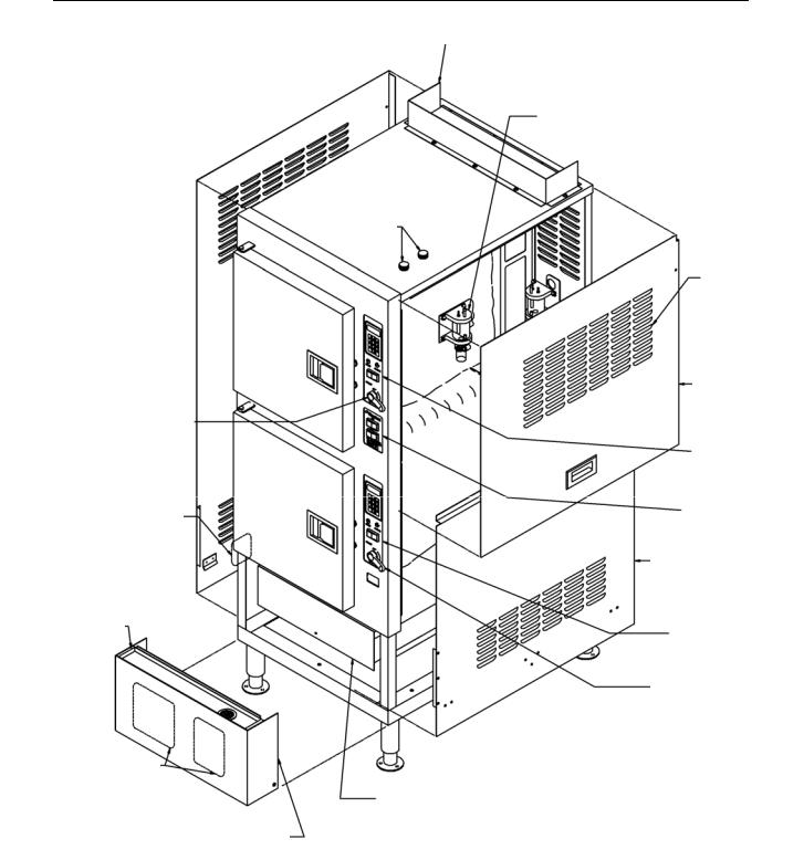
E. 24CGA10.2 PRODUCT VIEW
POWER ON/OFF CONTROLS (UPPER)
PRODUCT INFO
PLATE ON LEFT
ACCESS PANEL
DRIP TRAY
WIRING DIAGRAMS ARE
LOCATED ON THE BACK OF
FRONT ACCESS PANEL
FRONT ACCESS PANEL
FLUE OUTLET
WATER LEVEL PROBE HOUSINGS
LEFTLOWER COMPARTMENT
RIGHTUPPER COMPARTMENT
DESCALING
PORTS
AIR VENTS
RIGHT SIDE
SERVICE
PANEL
CONTROL PANEL (UPPER)
DESCALE INDICATOR
SWITCH PANEL
RIGHT SIDE
SERVICE PANEL
CONTROL PANEL (LOWER)
POWER ON/OFF CONTROL (LOWER)
NOTE: NOT ALL DETAILS ARE SHOWN
MAIN
CONTROL
DRAWER
Figure 1-3. Gemini 10-Pan Dual Atmospheric Steam Generator
and Convection Steamer
3
CHAPTER 2 INSTALLATION INSTRUCTIONS
A. GENERAL
This equipment should only be installed by qualified, professional plumbers, pipe fitters, and electricians.
The installation of this steamer must conform with the Basic Plumbing Code of the Building Officials and Code Administrators International, Inc. (BOCA), the National Fuel Gas Code, ANSI Z223.1-(latest edition) or the Natural Gas Installation Code CAN/CGA-B149.1 or the Propane Installation Code CAN/CGA-B149.2 as applicable, The National Electrical Code, ANSI/NFPA No. 70-(latest edition) or the Canadian Electrical Code, CSA C22.2 as applicable, the Food Service Sanitation Manual of the Food and Drug Administration (FDA) and all applicable state and local codes and regulations.
The installation instructions must be read in their entirety before starting the installation of this steamer.
 WARNING
DEATH, INJURY, AND EQUIPMENT DAMAGE could result from the improper installation, adjustment, alteration, service or maintenance of a steamer or installation of a unit damaged during shipment or storage. Any of these conditions could also void the equipment warranty.
DO NOT INSTALL a Gemini steamer that has been damaged.
Install the Gemini steamer according to the policies and procedures outlined in this manual.
To install this steamer, the following requirements must be considered when selecting a location.
a.A suitable drain must be available within 12 ft. of the steamer.
b.An electrical supply matching the power requirements found on the rating plate must be available.
c.A gas supply matching the fuel requirements found on the rating plate must be available.
d.The location must have sufficient space to meet the clearance requirements of the steamer as outlined in Chapter 2, Section B, Part 1, “Locating the Steamer”.
e.A water supply meeting the requirements outlined in Chapter 2, Section B, Part 6 “Water Supply Requirements and Installation” must be available.
B. INSTALLATION OF THE STEAMER
After selecting the steamer’s operating location the steamer can be positioned, and installed. After Final Setup and Checkout, the Gemini steamer should provide years of reliable operation.
4

 CAUTION
Malfunctions and equipment damage may result from improper mounting. Malfunctions and/or damage resulting from improper mounting are not covered by the equipment warranty.
The steamer MUST BE LEVEL BOTH FRONT TO BACK AND
SIDE TO SIDE in all mounting arrangements.
Catastrophic damage will result from shifting the steamer more than 10o out of level with power supplied to the unit.
1.Locating the Steamer
a.Location and Clearance Requirements of the Steamer
For safe and efficient operation, observe the following criteria when selecting an operating location for the Gemini steamer.
1)The unit should be installed in an area that is free and clear of combustible materials.
2)Do not locate the steamer directly over a floor drain.
3)A proper air supply for combustion and ventilation is critical to safe, efficient operation of Gemini gas steamers.
4)Do not install any heat producing equipment near the air vents of the equipment. Do not block the air vents of the unit. Do not store articles on top of the unit.
|
|
|
|
|
|
WARNING |
|
|
|
|
|
|
|
All clearance requirements above, below, and |
|
. |
|
around the unit are the same for non-combustible |
|
|
locations as for combustible locations. |
|
|
|
|
|
|
|
|
|
|
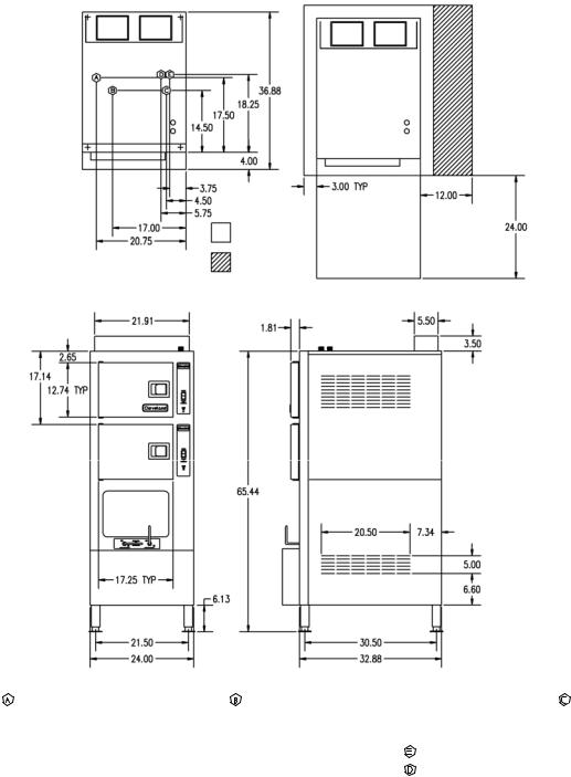
5)Figure 2-1 and 2-2 illustrate the dimensions and clearances required for these steamers. Maintain the following minimum dimensions around the unit for safe and efficient operation, maintenance and service.
Maintain a 3-inch operating clearance at the sides of the unit, and at least a 3-inch clearance at the back.
A 12 in clearance is recommended on the right side for servicing the steamer.
Approximately 24 inches of clearance is recommended in front of the unit for opening the door and standard pan clearance.
6)The steamer must be level both front to back and side to side. Select an operating surface that is level enough to allow leveling the unit without extreme adjustment of the legs.
7)The location selected must be capable of supporting 650 lbs. for a Gemini steamer. This includes the weight of the water and the food.
5
OPERATING
CLEARANCE
SECONDARY
CLEARANCE
|
GAS |
|
ELECTRIC |
COLD WATER |
CLEARANCE |
DRAINAGE |
||||
1-1/4" IPS line size, 3/4" connection |
120V-1Phase, 60 Hz. |
35 PSI minimum |
RIGHT = 12.00" for service |
1-1/2" dia. |
||||||
|
|
|
2 Fans & controls |
60 psi maximum |
SIDES |
= |
3.00” |
Do not connect other |
||
NATURAL |
PROPANE |
BTU |
||||||||
|
|
|
150 watts each |
(1) 3/8" dia. IPS for |
|
|
REAR |
= |
3.00” |
units to this drain |
Piping 3/4" N.P.T |
Piping 3/4" N.P.T. |
50,000 |
||||||||
|
|
each |
|
Generator |
|
|
|
|
|
|
|
|
|
|
|
|
|
|
|||
Supply pressure |
Supply pressure |
Generator |
|
(1) 3/8" dia. IPS for |
FRONT = |
24.00” |
|
|||
4.50" W.C. Min. |
11.00" W.C. Min. |
|
|
Condenser |
|
|
|
Drain must be vented |
||
14.00” W.C. Max. |
14.00” W.C. Max. |
100,000 total |
|
|
|
|
|
|
|
|
|
|
|
|
|
|
|
|
|
|
Do not use PVC pipe |
|
|
|
|
|
|
|
|
|
|
|
Manufacturer must |
be notified if unit will |
|
|
|
|
|
|
|
|
|
be used above 2,000 feet |
|
|
|
|
|
|
|
|
|
|
|
|
|
|
|
|
|
|
|
|
|
Figure 2-1 Gemini 24CGA6.2 Dimensions and Clearances
6
 Loading...