


Operators Manual
Installation, Operation & Service
Electric Table Top Kettles
MODELS:
Single Kettles
KET-3-T
KET-6-T
KET-12-T
KET-20-T*
Twin Kettles
TKET-3-T
TKET-6-T
TKET-12-T
*Floor Type Leg Mount
|
|
|
|
|
™ |
|
|
Cleveland |
1333 East 179th St., Cleveland, Ohio, U.S.A. 44110 |
||
|
|
|
|
|
Enodis |
Phone: (216) 481-4900 Fax: (216) 481-3782 |
|
|
|
Visit our web site at www.clevelandrange.com |
|
|
|
|
SE95004 Rev. 8 |

For your safety
DANGER
Keep clear of pressure |
Keep hands away from |
relief discharge. |
moving parts and pinch points. |
IMPORTANT
Inspect unit daily for |
Do not fill kettle above |
|
recommended level |
||
proper operation. |
||
marked on outside of kettle. |
||
|
CAUTION
Surfaces may be extremely hot! Use
Wear protective equipment
protective equipment.
when discharging hot product.
Do not lean on or place objects on kettle lip.
Stand clear of product discharge path when discharging hot product.
SERVICING
Shut off power at main |
|
Ensure kettle is at room |
|
fuse disconnect prior |
0 |
temperature and pressure |
|
to servicing. |
gauge is showing zero or less |
||
|
prior to removing any fittings.
GAS APPLIANCES
Do not attempt to operate this appliance during a power failure.
Keep appliance and area free and clear of combustibles.
INSTALLATION
GENERAL
Installation of the kettle must be accomplished by qualified electrical installation personnel working to all applicable local and national codes. Improper installation of product could cause injury or damage.
This equipment is built to comply with applicable standards for manufacturers. Included among those approval agencies are: UL, NSF, ASME/Ntl. Bd., CSA, CGA, ETL, and others. Many local codes exist, and it is the responsibility of the owner/installer to comply with these codes.
Note: Maximum voltage for LVD (low volt directive for Europe) to be 440 volts for CE marked appliances.
INSPECTION
Before unpacking visually inspect the unit for evidence of damage during shipping.
If damage is noticed, do not unpack the unit, follow Shipping Damage Instructions shown below.
SHIPPING DAMAGE
INSTRUCTIONS
If shipping damage to the unit is discovered or suspected, observe the following guidelines in preparing a shipping damage claim.
1.Write down a description of the damage or the reason for suspecting damage as soon as it is discovered. This will help in filling out the claim forms later.
2.As soon as damage is discovered or suspected, notify the carrier that delivered the shipment.
3.Arrange for the carrier's representative to examine the damage.
4.Fill out all carrier claims forms and have the examining carrier sign and date each form.
INSTALLATION
The first installation step is to refer to the Specification Sheets or Specification Drawings for detailed clearance requirements of the kettle. Next, carefully cut open the shipping carton for easy removal of the kettle.
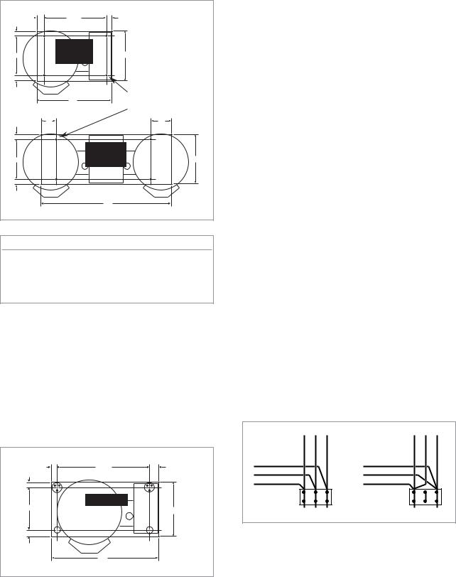
CLEARANCE REQUIREMENTS
Model # |
Back* |
Left Side |
Right Side |
|
|
|
|
|
|
KET-3-T |
2 1/4” |
0 |
0 |
|
KET-6-T |
2 3/4” |
0 |
0 |
|
KET-12-T |
5 1/2” |
0 |
0 |
|
KET-20-T |
8” |
0 |
0 |
|
TKET-3-T |
6 5/8” |
0 |
0 |
|
TKET-6-T |
7 1/8” |
0 |
0 |
|
TKET-12-T |
9 7/8” |
0 |
0 |
|
|
|
|
|
|
* From back of mounting base. |
|
|
|
|
|||||||||
POUR PATH |
|
|
|
|
|
|
|
|
|
|
|
|
|
|
|
|
|
|
|
|
|
|
|
|
|
||
|
|
|
|
|
|
|
|
|
|
|
|
|
|
|
Kettle Size |
Min. |
Max. |
|
|
|
|
|
|
|
|
|
|
|
|
|
|
|
|
|
|
|
|
||||
|
|
|
|
|
|
|
|
|
|
|
|
|
|
|
3 Gallon |
15 1/2” |
32” |
|
|
|
|
|
|
|
|
|
|
|
|
|
|
|
|
|
|
|
|
||||
|
|
|
|
|
|
|
|
|
|
||||
|
6 Gallon |
17 1/4” |
36” |
|
|
|
|
|
|
|
|
|
|
|
12 Gallon |
18” |
38” |
|
|
|
|
|
|
|
|
|
|
|
|
|
|
|
|
|
|
|
|
||||
|
20 Gallon |
22” |
45” |
|
|
|
|
|
|
|
|
|
|
|
|
|
|
|
|
|
Min. |
|
|||||
|
|
|
|
|
|
|
|
||||||
|
|
|
|
|
|
|
|
|
|
Max. |
|
||
|
|
|
|
|
|
|
|
|
|
|
|||
|
|
|
|
|
|
|
|
|
|
|
|
|
|
ASSEMBLY |
|
|
|
||
Table-Top Models (3, 6 & 12 gallon) |
|||||
1.25" |
|
14.5" |
1.25" |
|
|
1.25" |
|
|
|
|
|
|
|
KET-3-T |
|
|
|
10" |
|
KET-6-T |
12.5" |
|
|
|
|
KET-12-T |
|
|
|
1.25" |
|
|
|
5/16" - 18 |
|
|
|
|
|
|
|
|
|
18" |
|
threaded |
|
|
|
|
|
bushings |
|
1.25 " |
B |
|
|
C |
|
|
|
|
|
|
|
|
|
|
TKET-3-T |
|
|
10" |
|
|
TKET-6-T |
|
12.5" |
|
TKET-12-T |
|
|||
|
|
|
|
||
1.25 " |
|
|
|
|
|
|
|
|
A |
|
|
Model # |
|
|
A |
B |
C |
TKET-3-T |
|
18" |
2.25" |
1.25" |
|
TKET-6-T |
|
24" |
4.63" |
4.63" |
|
TKET-12-T |
30" |
7.75" |
7.75" |
||
Base Mounting Diagram
Table-top models (3, 6 & 12 gallon - single and twin) must be positioned on a firm, level stand, or existing counter top, and bolted in place. These models are supplied with four threaded mounting bushings welded to the underside of the base. An optional support stand with level adjustable legs is available. Once the kettle is secure, screw tilt handle into the threaded hole provided at the right side of kettle.
Floor Type Leg Mount Models (20 gallon)
1.25" |
28.5" |
2.25" |
1.25" |
|
|
|
KET-20-T |
|
12" |
|
14.5" |
|
|
|
1.25" |
|
|
|
32" |
|
Position on a firm, level surface, and bolt two flange feet in place. Once the kettle is secure, screw tilt handle into the threaded hole provided at the right of kettle.
ELECTRICAL
ENSURE THE ELECTRICAL SUPPLY MATCHES THE KETTLE'S REQUIREMENTS AS STATED ON THE RATING LABEL.
This kettle is built to comply with applicable standards of manufacturers. Included among these approval agencies are UL, NSF, ASME/Ntl. Bd., CSA, ETL, and others. Many local codes exist, and it is the responsibility of the owner and installer to comply with these codes.
The electrical supply must match the power requirements specified on the kettle’s rating plate. The copper wiring must be adequate to carry the required current at the rated voltage.
Note: Maximum voltage for LVD (low volt directive for Europe) to be 440 volts for CE marked appliances.
WIRE CONNECTION
If unit does not have cord and plug option, remove the four screws securing the console cover and remove the cover. A wiring diagram is affixed to the underside of the cover. Feed permanent copper wiring through the cut-out in the rear or bottom of the console, and fasten to the three connection terminal block, which is mounted on the top of the console’s control panel. Be sure to connect the ground wire to the separate ground terminal connector (ground lug). Replace console cover and secure it with the four screws.
THREE PHASE
RED YELLOW BLACK
BLACK |
BLUE |
RED |
L1 |
L2 |
L3 |
SINGLE PHASE
RED YELLOW BLACK
BLACK |
BLUE |
RED |
L1 |
L2 |
The kettle is wired for 3-phase operation at the factory. For single phase operation, rewire the terminal block to that shown in the above diagram.
Base Mounting Diagram
WATER

The sealed jacket of the electric kettle is precharged with the correct amount of a water based formula, and therefore, no water connection is required to the kettle jacket. The kettle can be equipped with optional hot and/or cold water faucet, requiring 1/2" copper tubing as supply lines.
INSTALLATION CHECKS
Although the kettle has been thoroughly tested before leaving the factory, the installer is responsible for ensuring the proper operation of kettle once installed.
Visual Checks
1.Check Marine Lock. See Marine Lock Testing Procedure.
2.Check Tilting:
A/ Handle is in place and firmly tightened.
B/ Kettle tilts smoothly and freely.
3.Insure there are:
A/ Four screws securely holding the console cover.
B/ The bottom cover is in place and held with a nut.
Performance Checks
1.Supply power to the kettle by placing the fused disconnect switch to the "ON" position.
2.Before turning the kettle on, read the
|
|
150 |
200 |
|
|
|
100 |
|
250 |
|
|
|
|
20 |
|
|
|
50 |
30 |
|
|
||
10 |
|
40 |
300 |
||
|
|
|
|||
|
|
|
|
||
0 |
0 |
|
|
50 |
|
|
I |
|
|
|
|
|
R |
|
|
|
350 |
|
A |
|
|
|
|
|
T |
|
|
|
|
|
N |
|
60 |
|
|
|
E |
|
|
|
|
|
V |
|
psi |
|
400 |
|
|
|
|
||
|
|
|
|
kPa |
|
MARINE LOCK
Your unit is equipped with a
LATCH
marine lock to prevent accidental tilting. The following procedure should be used to tilt the kettle.
1. Grasp the tilt handle.
Vacuum/Pressure Gauge (2). The gauge's needle should be in the green zone. If the needle is in the "VENT AIR" zone, follow Kettle Venting Instructions.
3.Turn the kettle's ON/OFF Switch/Solid State Temperature Control (5) to "1" (Min.). The Heat Indicator Light (Green) (6) should remain lit, indicating the element is on, until the set temperature is reached (130°F/54°C). Then the green light will cycle on and off, indicating the element is cycling on and off to maintain temperature.
4.Tilt the kettle forward. After a few seconds the Low Water Indicator Light (Red) (4) should be lit when the kettle is in a tilted position. This light indicates that the element has automatically been shut off by the kettle's safety circuit. This is a normal condition when the kettle is in a tilted position.
5.Raise the kettle to the upright position. The Low Water Indicator Light (Red) (4) should go out when the kettle is upright.
6.Turn the ON/OFF Switch/Solid State Temperature Control (5) to "10" (Max.) and allow the kettle to preheat. The green light should remain on until the set temperature (260°F/127°C) is reached. Then the green light will cycle ON and OFF, indicating the element is cycling ON and OFF to maintain temperature. Fill the kettle with cold water to the steam jacket’s welded seam. Refer to the Temperature Range Chart for the time required to bring the water to a boil.
7.When all testing is complete, empty the kettle and turn the ON/OFF Switch/Solid State Temperature Control (5) to the “OFF” position.
CLEANING
After installation the kettle must be thoroughly cleaned and sanitized prior to cooking. See Cleaning Instructions.
2.Hold the latch down to unlock tilting mechanism.
3.Pull the handle to tilt kettle.
4.To lock, return the kettle to its upright position and push handle back.
NOTE: Inspect lock daily to ensure it is free moving and does not bind or stick. Clean lock if necessary (see Cleaning Instructions for details).
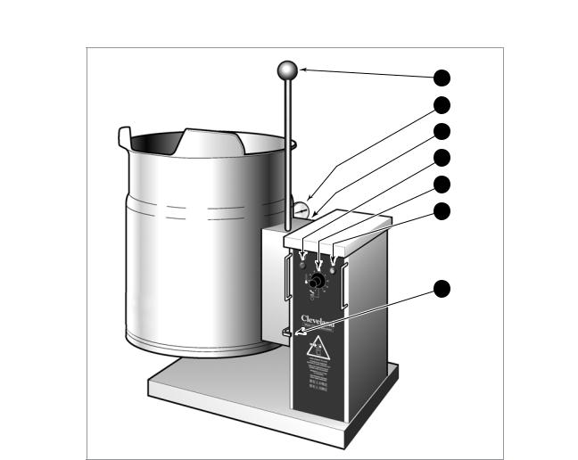
OPERATING INSTRUCTIONS
1 |
2 |
3 |
4 |
5 |
6 |
7 |
|
General Parts Drawing |
|
ITEM # |
DESCRIPTION |
FUNCTION |
1. |
Tilting Handle |
Used for tilting the kettle. |
2. |
Vacuum/Pressure Gauge |
Indicate steam pressure in PSI inside steam jacket as well as |
|
|
vacuum in inches of mercury. |
3. |
Pressure Relief Valve |
This valve is used to vent the kettle and in the unlikely event there is |
|
(not shown) |
an excess steam build-up in the jacket, this valve opens |
|
|
automatically to relieve this pressure. |
4. |
Low Water Indicator Light (Red) |
When lit, it indicates that the kettle is low on water and will not |
|
|
operate in this condition. This will also light when the kettle is tilted. |
5. |
On-Off Switch/ |
Turns kettle ON/OFF and allows the operator to adjust the kettle |
|
Solid State Temperature |
temperature in increments from 1 (Min.) to 10 (Max.). |
|
Control |
(see Temperature Range Chart). |
6. |
Heat Indicator Light (Green) |
When lit, indicates that the kettle's element is on. |
|
|
Cycles ON-OFF with element. |
7. |
Marine Lock |
Prevents unit from accidental tilting. |
OPERATING THE KETTLE
DO NOT LEAN ON OR PLACE OBJECTS ON KETTLE LIP. SERIOUS INJURY COULD RESULT IF KETTLE TIPPED OVER, SPILLING HOT CONTENTS.
1.Before turning kettle on, read the Vacuum/Pressure Gauge (2). The gauges needle should be in the green zone. Once heated, the kettle's normal maximum operating pressure is approximately 10-12 psi, while cooking a water base product.
2.Ensure that the electrical service to the kettle is turned on at the fused disconnect switch.
Temperature |
Approximate |
|
Control |
Product Temperature |
|
Setting |
°F |
°C |
|
|
|
1. (Min.) |
130 |
54 |
2. |
145 |
63 |
3. |
160 |
71 |
4. |
170 |
77 |
5. |
185 |
85 |
6. |
195 |
91 |
7. |
210 |
99 |
8. |
230 |
110 |
9. |
245 |
118 |
10. (Max.) |
260 |
127 |
NOTE: Certain combinations of ingredients will result in temperature variations
Temperature Range Chart
3.Preheat the kettle by turning the ON/OFF Switch/Solid State Temperature Control (5) to the desired temperature setting (see above "Temperature Range Chart"). The Heat Indicator Light (Green) (6) will remain lit, indicating the element is on, until the temperature setting is reached. When the green light goes off, the elements are off, and preheating is complete.
NOTE: When cooking egg and milk products, the kettle should not be preheated, as products of this nature adhere to hot cooking surfaces. These types of food should be placed in the kettle before heating is begun.
4.Place food product into the kettle. The Heat Indicator Light (Green) (6) will cycle on and off indicating the elements are cycling on and off to maintain the set temperature.
NOTE: Do not fill kettle above recommended level marked on outside of kettle.
NOTE: The Low Water Indicator Light (Red) (4) should not be lit when kettle is in upright position during operation. This light indicates that the elements have been automatically shut off by the kettle's safety circuit. It is, however, normal for the red light to come on when the kettle is in a tilted position.
5.When cooking is completed turn ON/OFF Switch/Solid State Temperature Control (5) to the "OFF' position.
6.Pour the contents of the kettle into an appropriate container by tilting the kettle forward. Care should be taken to pour slowly enough to avoid splashing off the product.
NOTE: As with cleaning food soil from any cookware, an important part of kettle cleaning is to prevent food from drying on. For this reason, cleaning should be completed immediately after cooked foods are removed.
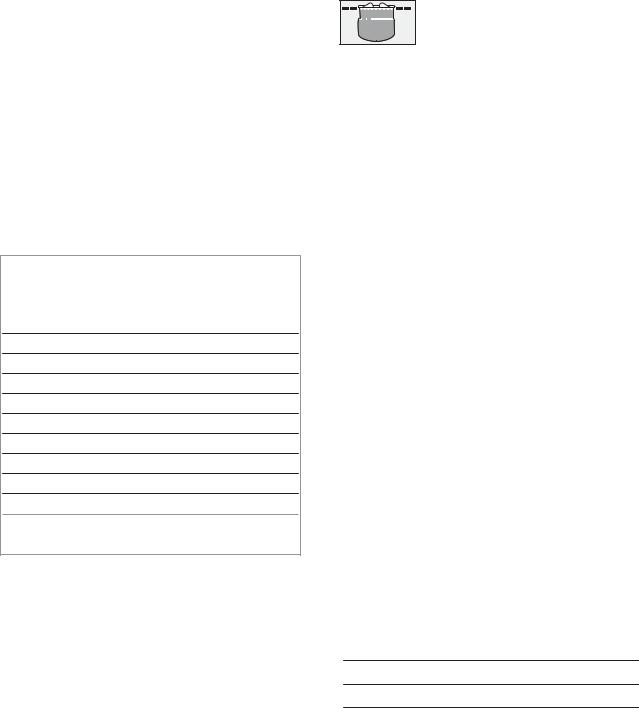
APPROXIMATE BOILING TIMES
The accompanying chart shows approximate times required for electric kettles of various capacities to boil water. The ON/OFF Switch/Solid State Temperature Control must be set at “10” (Max.) throughout the heat-up period. Water will boil about 1/3 faster if the kettle is filled only to the outer steam jacket’s welded seam resulting in a kettle filled to 2/3 capacity.
Kettle Capacity |
Minutes |
|
|
3 gallon/11 litre |
15 |
6 gallon/23 litre |
20 |
12 gallon/45 litre |
25 |
20 gallon/80 litre |
40 |
|
|
Approximate Boiling Times

CLEANING INSTRUCTIONS
CAUTION
SURFACES MAY
BE EXTREMELY HOT!
CARE AND CLEANING
Cooking equipment must be cleaned regularly to maintain its fast, efficient cooking performance and to ensure its continued safe, reliable operation. The best time to clean is shortly after each use (allow unit to cool to a safe temperature).
WARNINGS
|
Do not use detergents or |
|
cleansers that are chloride |
|
based or contain quaternary |
|
salt. |
|
Chloride Cleaners |
|
Do not use a metal bristle |
|
brush or scraper. |
|
Wire Brush & |
|
Steel wool should never be |
|
used for cleaning the stainless |
|
steel. |
|
Steel Pads |
|
Unit should never be cleaned |
|
with a high pressure spray |
|
hose. |
|
High Pressure |
|
Spray Hose |
|
Do not leave water sitting in unit |
|
when not in use. |
Stagnant
Water
CLEANING INSTRUCTIONS
1.Turn unit off.
2.Remove drain screen (if applicable). Thoroughly wash and rinse the screen either in a sink or a dishwasher.
3.Prepare a warm water and mild detergent solution in the unit.
4.Remove food soil using a nylon brush.
5.Loosen food which is stuck by allowing it to soak at a low temperature setting.
6.Drain unit.
7.Rinse interior thoroughly.
8.If the unit is equipped with a Tangent Draw-Off Valve, clean as follows:
a)Disassemble the draw-off valve first by turning the valve knob counter-clockwise, then turning the large hex nut counter-clockwise until the valve stem is free of the valve body.
b)In a sink, wash and rinse the inside of the valve body using a nylon brush.
c)Use a nylon brush to clean tangent draw-off tube.
d)Rinse with fresh water.
e)Reassemble the draw-off valve by reversing the procedure for disassembly. The valve's hex nut should be hand tight only.
9.If the unit is equipped with a Butterfly Valve, clean as follows:
a)Place valve in open position.
b)Wash using a warm water and mild detergent solution.
c)Remove food deposits using a nylon brush.
d)Rinse with fresh water.
e)Leave valve open when unit is not in use.
10.Using mild soapy water and a damp sponge, wash the exterior, rinse, and dry.
NOTES
For more difficult cleaning applications one of the following can be used: alcohol, baking soda, vinegar, or a solution of ammonia in water.
Leave the cover off when the kettle is not in use.
For more detailed instructions refer to the Nafem Stainless Steel Equipment Care and Cleaning manual (supplied with unit).
6
STAINLESS STEEL EQUIPMENT CARE AND CLEANING
(Suppied courtesy of Nafem. For more information visit their web site at www.nafem.org)
Contrary to popular belief, stainless steels ARE susceptible to rusting. |
4. |
Treat your water. |
|
|
||
Corrosion on metals is everywhere. It is recognized quickly on iron and |
|
Though this is not always practical, softening hard water can do much |
||||
steel as unsightly yellow/orange rust. Such metals are called “active” |
|
to reduce deposits. There are certain filters that can be installed to |
||||
because they actively corrode in a natural environment when their atoms |
|
remove distasteful and corrosive elements. To insure proper water |
||||
combine with oxygen to form rust. |
|
treatment, call a treatment specialist. |
|
|||
Stainless steels are passive metals because they contain other metals, like |
5. |
Keep your food equipment clean. |
|
|||
chromium, nickel and manganese that stabilize the atoms. 400 series |
|
Use alkaline, alkaline chlorinated or non-chloride cleaners at |
||||
stainless steels are called ferritic, contain chromium, and are magnetic; |
|
|||||
|
recommended strength. Clean frequently to avoid build-up of hard, |
|||||
300 series stainless steels are called austenitic, contain chromium and |
|
|||||
|
stubborn stains. If you boil water in stainless steel equipment, |
|||||
nickel; and 200 series stainless, also austenitic, contains manganese, |
|
|||||
|
remember the single most likely cause of damage is chlorides in the |
|||||
nitrogen and carbon. Austenitic types of stainless are not magnetic, and |
|
|||||
|
water. Heating cleaners that contain chlorides have a similar effect. |
|||||
generally provide greater resistance to corrosion than ferritic types. |
|
|||||
6. |
Rinse, rinse, rinse. |
|
|
|||
With 12-30 percent chromium, an invisible passive film covers the steel’s |
|
|
||||
|
If chlorinated cleaners are used, rinse and wipe equipment and |
|||||
surface acting as a shield against corrosion. As long as the film is intact |
|
|||||
and not broken or contaminated, the metal is passive and stain-less. If the |
|
supplies dry immediately. The sooner you wipe off standing water, |
||||
passive film of stainless steel has been broken, equipment starts to |
|
especially when it contains cleaning agents, the better. After wiping |
||||
corrode. At its end, it rusts. |
|
equipment down, allow it to air dry; oxygen helps maintain the |
||||
Enemies of Stainless Steel |
|
stainless steel’s passivity film. |
|
|||
7. |
Never use hydrochloric acid (muriatic acid) on stainless steel. |
|||||
There are three basic things which can break down stainless steel’s |
||||||
8. |
Regularly restore/passivate stainless steel. |
|||||
passivity layer and allow corrosion to occur. |
||||||
1. |
Mechanical abrasion |
|
|
|
|
|
2. |
Deposits and water |
Recommended cleaners for specific situations |
||||
3. |
Chlorides |
Job |
|
Cleaning Agent |
Comments |
|
Mechanical abrasion means those things that will scratch a steel surface. |
Routine cleaning |
Soap, ammonia, |
Apply with cloth or sponge |
|||
|
|
detergent, Medallion |
|
|||
Steel pads, wire brushes and scrapers are prime examples. |
|
|
|
|||
|
|
|
|
|||
Fingerprints & smears |
Arcal 20, Lac-O-Nu |
Provides barrier film |
||||
Water comes out of the faucet in varying degrees of hardness. Depending |
||||||
|
|
Ecoshine |
|
|||
on what part of the country you live in, you may have hard or soft water. |
|
|
|
|
||
Stubborn stains & |
Cameo, Talc, Zud, |
Rub in direction of polish lines |
||||
Hard water may leave spots, and when heated leave deposits behind that |
||||||
discoloration |
First Impression |
|
||||
if left to sit, will break down the passive layer and rust stainless steel. Other |
|
|
|
|
||
Grease & fatty acids, |
Easy-off, De-Grease |
Excellent removal on all finishes |
||||
deposits from food preparation and service must be properly removed. |
||||||
blood, burnt-on-foods |
It Oven Aid |
|
||||
Chlorides are found nearly everywhere. They are in water, food and table |
|
|
|
|||
Grease & oil |
Any good |
Apply with sponge or cloth |
||||
salt. One of the worst chloride perpetrators can come from household and |
|
|
commercial detergent |
|
||
industrial cleaners. |
Restoration/Passivation |
Benefit, Super Sheen |
|
|||
So what does all this mean? Don’t Despair! |
|
|
|
|
||
Review |
|
|
||||
Here are a few steps that can help prevent stainless steel rust. |
|
|
||||
1. |
Stainless steels rust when passivity (film-shield) breaks down as a |
|||||
1. |
Use the proper tools. |
|||||
|
result of scrapes, scratches, deposits and chlorides. |
|||||
|
|
|
||||
|
When cleaning stainless steel products, use non-abrasive tools. Soft |
2. |
Stainless steel rust starts with pits and cracks. |
|||
|
cloths and plastic scouring pads will not harm steel’s passive layer. |
|||||
|
3. |
Use the proper tools. Do not use steel pads, wire brushes or scrapers |
||||
|
Stainless steel pads also can be used but the scrubbing motion must |
|||||
|
be in the direction of the manufacturers’ polishing marks. |
|
to clean stainless steel. |
|
||
2. |
Clean with the polish lines. |
4. |
Use non-chlorinated cleaners at recommended concentrations. Use |
|||
|
Some stainless steel comes with visible polishing lines or “grain.” |
|
only chloridefree cleaners. |
|
||
|
5. |
Soften your water. Use filters and softeners whenever possible. |
||||
|
When visible lines are present, always scrub in a motion parallel to the |
|||||
|
lines. When the grain cannot be seen, play it safe and use a soft cloth |
6. |
Wipe off cleaning agent(s) and standing water as soon as possible. |
|||
|
or plastic scouring pad. |
|
Prolonged contact causes eventual problems. |
|||
3. Use alkaline, alkaline chlorinated or non-chloride containing cleaners.
While many traditional cleaners are loaded with chlorides, the industry is providing an ever-increasing choice of non-chloride cleaners. If you are not sure of chloride content in the cleaner used, contact your cleaner supplier. If your present cleaner contains chlorides, ask your supplier if they have an alternative. Avoid cleaners containing quaternary salts; it also can attack stainless steel and cause pitting and rusting.
To learn more about chloride-stress corrosion and how to prevent it, contact the equipment manufacturer or cleaning materials supplier.
Developed by Packer Engineering, Naperville, Ill., an independent testing laboratory.
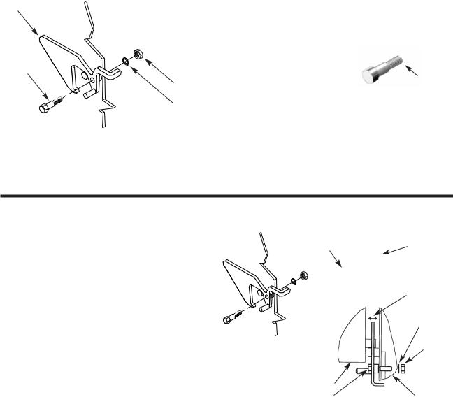
MARINE LOCK
Use a small nylon bristle brush to remove food and debris from pivot point. If lock is still sticking have maintenance disassemble and clean pieces individually and reassemble.
Latch
Shoulder Bolt
Locknut
Lockwasher
Disassembly
1.Disconnect power from kettle.
2.Remove console cover from top of kettle's console.
3.Remove locknut and lockwasher from inside console.
4.Remove shoulder bold from latch.
5.Clean all parts.
Re-Assembly |
|
|
6. Apply locktight to |
|
|
shoulderbolt where |
|
|
illustrated. Replace |
|
|
Carefully apply |
||
shoulder bolt and latch |
locktight to the |
|
final two threads. |
||
and tighten firmly. |
||
|
7.Replace lockwasher and locknut inside the console and tighten firmly.
8.Test Marine Lock. See Marine Lock Testing Procedure.
9.Replace console cover.
MARINE LOCK TESTING PROCEDURE
1.Check that lock clears stop pin on side box without rubbing when kettle is tilted (Figure A).
2.Check side to side play. Lock should remain fully over stop pin when pushed to it's maximum side to side play (Figure B).
3.Check that the kettle when pushed fully upright moves the lock to a closed position. To check this:
A/ Hold the latch firmly in the unlocked position while tilting the kettle back to an upright position.
B/ The kettle sidebox will force the lock into a new position.
C/ Hold the lock in this position and try to tilt the kettle forward. The latch should prevent the kettle from tilting.
Stop Pin on
Sidebox Marine Lock (Latch)
Figure A |
|
|
|
Side to Side Play |
|||
(Side View) |
|
||
|
|
||
|
|
|
Lockwasher
Locknut
Side Box
Shoulder Bolt |
Figure B |
Console |
(Top View) |
||
|
|
|
4.Check shoulder bolt is firmly seated against console body.
5.Check on inside of console box that shoulder bolt locknut is secure.
 Loading...