


Operators Manual
Installation, Operation & Service
GAS MIXING KETTLES
HORIZONTAL AGITATOR
MODEL: HA-MKGL-60 HA-MKGL-80 HA-MKGL-100
HA-MKGL-60-CC
HA-MKGL-80-CC
HA-MKGL-100-CC
HA-MKGL-60-T HA-MKGL-80-T HA-MKGL-100-T
HA-MKGL-60-CC-T HA-MKGL-80-CC-T HA-MKGL-100-CC-T
|
™ |
|
Cleveland |
1333 East 179th St., Cleveland, Ohio, U.S.A. 44110 |
|
|
|
|
|
Enodis |
Phone: (216) 481-4900 Fax: (216) 481-3782 |
|
|
Visit our web site at www.clevelandrange.com |
|
|
SE95022 Rev. 5 |

FOR THE USER
IMPORTANT!
ENSURE KETTLE IS AT ROOM TEMPERATURE AND PRESSURE GAUGE IS SHOWING ZERO OR LESS PRESSURE PRIOR TO REMOVING ANY FITTINGS.
|
|
|
|
|
WARNING: Improper installation, |
|
|
FOR YOUR SAFETY |
|
|
|
|
|
|
|
|
|
|
adjustment, alteration, service or |
|
|
DO NOT STORE OR USE GASOLINE |
|
|
|
maintenance can cause property |
|
|
OR ANY OTHER |
|
|
|
damage, injury or death. Read the |
|
|
FLAMMABLE LIQUIDS AND |
|
|
|
installation and operating |
|
|
VAPOURS IN THE VICINITY |
|
|
|
instructions thoroughly before |
|
|
OF THIS OR ANY OTHER |
|
|
|
installing or servicing this |
|
|
APPLIANCE. |
|
|
|
equipment. |
|
|
|
|
|
|
|
|
|
|
|
|
|
|
|
.
IMPORTANT
The following points are to insure the safe installation and operation of this equipment:
•Insure all gas and electrical supplies match rating plate and electrical stickers.
•Observe all clearance requirements.
•Disconnect the electrical power supply to the appliance before cleaning or servicing unit.
•All service must be performed by a qualified Cleveland Range Technician.
•Do not obstruct the flow of combustion and ventilation air.
The installation and connection must comply with current local codes, or in the absence of local codes, with CAN/CGA-B149.1 and .2 installation code or with the national fuel gas code, ANSI Z223.1-L988.
Post in a prominent location, instructions to be followed in the event the user smells gas. This information shall be obtained by consulting your local gas supplier.
The appliance and its individual shut off valve must be disconnected from the gas supply piping system during any pressure testing of that system at test pressures in excess of 1/2 psig. (3.45 kpa).
The appliance must be isolated from the gas supply piping system by closing its individual manual shut off valve during any pressure testing of the gas supply piping system at test pressures equal to or less than 1/2 psig. (3.45 kpa).
RETAIN THIS MANUAL FOR YOUR REFERENCE.
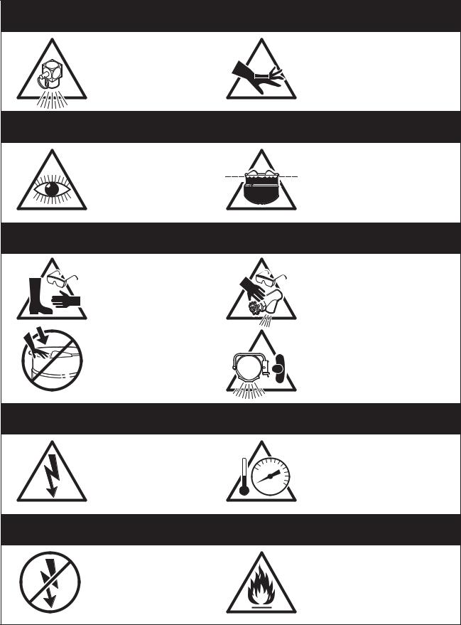
For your safety
DANGER
Keep clear of pressure |
|
Keep hands away from |
relief discharge. |
|
moving parts and pinch points. |
|
IMPORTANT
Inspect unit daily for |
Do not fill kettle above |
|
recommended level |
||
proper operation. |
||
marked on outside of kettle. |
||
|
CAUTION
Surfaces may be extremely hot! Use
Wear protective equipment
protective equipment.
when discharging hot product.
Do not lean on or place objects on kettle lip.
Stand clear of product discharge path when discharging hot product.
SERVICING
Shut off power at main |
|
Ensure kettle is at room |
|
fuse disconnect prior |
0 |
temperature and pressure |
|
to servicing. |
gauge is showing zero or less |
||
|
prior to removing any fittings.
GAS APPLIANCES
Do not attempt to operate this appliance during a power failure.
Keep appliance and area free and clear of combustibles.
INSTALLATION
GENERAL
Installation of the kettle must be accomplished by qualified installation personnel working to all applicable local and national codes. Improper installation of product could cause injury or damage.
This equipment is built to comply with applicable standards for manufacturers. Included among those approval agencies are: UL, A.G.A., NSF, ASME/N.Bd., CSA, CGA, ETL, and others. Many local codes exist, and it is the responsibility of the owner/installer to comply with these codes.
Observe all clearance requirements to provide proper makeup air flow as well as sufficient clearance for servicing.
Dimensions and clearance specifications are shown on the specification sheet and in the Clearance Requirements section. Do not install kick plates or otherwise obstruct the flow of combustion and ventilation air.
Check rating plate to ensure that kettle has been equipped to operate with the type of gas available at the installation.
VENTILATION
Gas fired kettles are only to be installed under a ventilation hood in a room which has provisions for adequate make up air. Further information can be obtained by referring to the U.S.A. National Fire Protection Associations NFPA96 regulations. These standards have also been adopted by the National
Building Code in Canada.
INSPECTION
Before unpacking visually inspect the unit for evidence of damage during shipping. If damage is noticed, do not unpack the unit, follow shipping damage
instructions.
SHIPPING DAMAGE
INSTRUCTIONS
If shipping damage to the unit is discovered or suspected, observe the following guidelines in preparing a shipping damage claim.
1.Write down a description of the damage or the reason for suspecting damage as soon as it is discovered. This will help in filling out the claim forms later.
2.As soon as damage is discovered or suspected, notify the carrier that delivered the shipment.
3.Arrange for the carrier's representative to examine the damage.
4.Fill out all carrier claims forms and have the examining carrier sign and date each form.
CLEARANCE REQUIREMENTS
This unit must be installed in accordance with the clearances shown on the rating label which is adhered to the unit.
FOR YOUR SAFETY. Keep the appliance area free and clear of combustible materials.
KETTLE
1.When removing the kettle from the platform, handle with care to prevent scratching or any other damage. It is imperative that the kettle be level before bolting to the floor. This will prevent any twist or out of roundness to the kettle and will stop deflection of the agitator. Make sure the kettle is securely bolted to the floor and follow the procedure listed below:
Raise the flange on the leg under the motor so that it sets freely (stationary kettles only).
Position the kettle in its permanent location, check clearances and level the kettle by turning the adjustable feet.
Lower the flange or flanges under the motor channel. Over adjustment, whether up or down, could cause misalignment and cause damage to the agitator drive shaft and hub (stationary kettles only).
2.Next you must check the alignment of the drive shaft for a uniform clearance between the hub and the shaft. In order to check for clearance you must remove the seal cover plate and pull the seal back. you can check the distance for clearance by using a wire feeler gauge.
3.If adjustment is required for side direction, loosen the motor bolts, center the shaft and retighten.
If vertical alignment is needed, loosen the motor bolts and add a shim to raise or remove a shim to lower. Retighten bolts. When this is complete, check to see if the agitator shaft coupling slides freely for easy removal of the agitator.
4.Once positioned and leveled, permanently secure the kettle’s flanged feet to the floor using 1/2 x 2 I/2 inch lag bolts and floor anchors (supplied by the installer). Two bolts per leg are required to secure each of the flanged feet.
GAS
It is recommended that a sediment trap (drip leg) be installed in the gas supply line. If the gas pressure exceeds 14” water column, a pressure regulator must be installed, to provide a maximum of 14” water column gas pressure to the gas control valve.
Connect the gas supply piping to the input side of the gas control valve. Location and pressure data are shown on the specification sheet.
Installation must be in accordance with local codes and/or the National Fuel Gas Code ANSI Z223.1-1988 (USA) or the Installation Codes for Gas Burning Appliances and Equipment CANI B149.1 and B149.2 (Canada). Use a gas pipe joint compound which is resistant to L.P. gas. Test all pipe joints for leaks with soap and water solution. Ensure that the gas pressure regulator is set for the manifold pressure indicated on the gas rating plate.
The appliance and its individual shut-off valve must be disconnected from the gas supply piping system during any pressure testing of that system at test pressures in excess of 1/2 psi (3.45 kPa). The appliance must be isolated from the gas supply piping system by closing its individual manual shut-off valve during any pressure testing of the gas supply piping system at test pressures equal to or less than 1/2 psi (3.45 kPa).
ELECTRICAL
Electrical installation must be in accordance with local codes and/or the National Electric Code ANSI/NFPA 701990 (USA) or the Canadian Electrical Code CSA Standard C22.1 (Canada). The kettle must be electrically grounded by the installer.
A separate fused disconnect switch must be supplied and installed in the high voltage electrical supply line.
The wire gauge size and electric supply must match the power requirements specified on the kettle’s rating plate. The waterproof conduit enclosed permanent copper wiring must be adequate to carry the required current at the rated voltage. Refer to the specification sheet or rating label for electrical specifications and location of electrical connections.
Remove the screws securing the component cover (located to the left rear side of kettle), and remove the cover. A wiring diagram is affixed to the inside of the cover. Feed conduit enclosed permanent copper wiring through the cut-out in the bottom of the console and fasten to the terminal block. Fasten the ground wire to the ground lugs connected to the frame, beside the terminal block. Replace the console cover and secure it
with the screws.
WATER
The sealed jacket of the gas-fired kettle is precharged with the correct amount of a water-based formula, and therefore, no water connection is required to the kettle
jacket.
CLEANING
After installation the kettle must be thoroughly cleaned and sanitized prior to cooking.
WARRANTY
Our Company supports a worldwide network of Maintenance and Repair Centres. Contact your nearest Maintenance and Repair Centre for replacement parts, service, or information regarding the proper maintenance and repair of your cooking equipment
In order to preserve the various agency safety certification (UL, A.G.A., NSF, ASME/Ntl. Bd., etc.), only factory-supplied replacement parts should be used. The use of other than factory supplied replacement parts will void warranty.
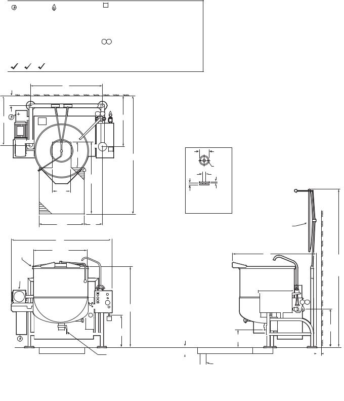
SPECIFICATION DRAWING - STATIONARY MODELS
ELECTRICAL |
GAS SUPPLY |
|
SUPPLY |
(PIPING 3/4" NPT) |
|
VOLTS: 208/240 |
TYPE: NAT or LP |
|
PHASE: 3 |
BTU PER CU. FT.: |
|
AMPS: |
15 |
1000 (NAT), 2500 (LP) |
|
|
|
FREQ: |
60 HZ |
SUPPLY PRESSURE: |
|
|
|
|
4" to 14" W.C. |
|
APPROVALS |
||
AGA CGA NSF |
BTU RATINGS: |
|
|
|
190,000 per hour |
|
|
|
A AIR SUPPLY (PIPING 1/2" NPT) |
APPROX. |
||
PRESSURE: |
|
SHIPPING |
|
|
WEIGHTS |
||
90 - 100 PSI |
|
|
|
(only required for optional 3" dia. |
60 GAL - |
||
piston draw-off valve) |
|
1010 LBS. |
|
|
|
|
458 KG. |
H C HOT & COLD |
|
CLEARANCE |
80 GAL - |
WATER |
|
RIGHT: 3", LEFT: 3" |
1120 LBS. |
1/2" NPT CONNECTION |
|
508 KG. |
|
|
REAR: 5" |
||
|
100 GAL - |
||
40-60 PSI PRESSURE |
|
(ALLOW 12" SPACE |
|
|
1325 LBS. |
||
|
|
MINIMUM ON LEFT |
|
|
|
601 KG. |
|
|
|
SIDE FOR SERVICE) |
|
|
|
|
|
|
|
G |
|
|
|
7 3/4" |
WALL |
|
|
|
|
|
|
|
|
|
|
H C |
|
F |
|
|
H |
|
|
|
|
|
|
|
|
16" |
A |
5 1/2" |
|
|
|
||
|
|
J |
5/8"Ø, |
|
|
|
|
||
|
|
|
|
2 HOLES |
|
|
|
|
ON |
|
|
|
|
4" B.C.D. |
|
|
|
|
2" |
|
M |
3/8" |
|
|
|
12" |
|
1" (MAX. ADJUSTMENT) |
RECOMMENDED |
|
SOLID |
FLOOR DRAIN |
|
|
|
|
FOOT DETAIL |
28" |
L |
SPRING ASSIST |
|
|
COVER (FULLY |
|
|
OPEN AT 90 ) |
C |
|
WALL |
|
|
|
A I.D. |
|
D |
RIM BAR |
|
|
|
|
E |
|
|
(COVER |
3 HP |
|
FULLY |
|
OPEN) |
|
ELECTRIC |
|
|
|
|
|
MOTOR |
|
|
|
H C |
B |
|
A |
A |
|
|
RECOMMENDED FLOOR |
T |
SLOPE 1 INCH PER 4 FEET |
|
S |
|
6" RECOMMENDED |
13" |
|
|
|
3" DIA. BUTTERFLY VALVE |
|
|
|
|
FLOOR DRAIN |
|
|
|
|
|
|
|
|
5" MIN |
||
|
|
|
|
|
|
|
|
|
|
|
|
|
|
|
|
||||
|
|
|
|
|
|
|
|
|
|
PIPE DRAIN RECOMMENDED |
|
|
|
|
CLEARANCE |
||||
|
|
|
|
|
|
|
|
|
|
|
|
|
|
||||||
|
|
|
|
|
|
|
|
|
|
|
|
|
|
|
|
|
|||
|
|
|
|
|
|
|
|
|
|
MINIMUM VALVE SIZE PLUS 1" |
|
|
|
|
|
|
|
||
DIMENSIONS |
|
|
|
|
|
|
|
|
|
|
|
|
|
|
|
|
|
|
|
|
|
|
|
|
|
|
|
|
|
|
|
|
|
|
|
|
|
||
MODEL |
A |
B |
C |
D |
E |
F |
|
G |
H |
J |
L |
M |
|
S |
|
|
T |
||
HA-MKGL-60-TCC |
29 1/2" |
48 1/4" |
61 5/8" |
46 3/4" |
93" |
27 3/4" |
42" |
30 5/8" |
78" |
10 3/8" |
53" |
19 1/4" |
24 1/2" |
||||||
HA-MKGL-80-TCC |
33" |
51 3/4" |
65 3/8" |
52" |
98" |
30 3/4" |
45 11/16" |
33 5/8" |
84" |
11 7/16" |
57" |
20 3/4" |
26 3/16" |
||||||
HA-MKGL-100-TCC |
35 1/2" |
54 1/4" |
68 3/8" |
55" |
104" |
32 3/4" |
48 3/16" |
35 5/8" |
95 5/8" |
11 5/8" |
66" |
22" |
|
27 5/8" |
|||||
NOTES: CLEVELAND RANGE EQUIPMENT IS BUILT TO COMPLY WITH APPLICABLE STANDARDS FOR MANUFACTURERS. INCLUDED AMONG THOSE APPROVAL AGENCIES ARE: UL, A.G.A., NSF, ASME/N.BD., CSA, CGA, ETL, AND OTHERS. INSTALLATIONS OF BACK FLOW PREVENTERS, VACUUM BREAKERS AND OTHER SPECIFIC CODE REQUIREMENTS ARE THE RESPONSIBILITY OF THE OWNER AND INSTALLER.
ALL VERTICAL DIMENSIONS SHOWN ARE MINIMUM. FEET ARE ADJUSTABLE TO +1" MAXIMUM. MANUFACTURER MUST BE NOTIFIED IF UNIT WILL BE OPERATING ABOVE 2000' ALTITUDE. CONSULT FACTORY FOR MANUFACTURED GAS.
Cleveland Range reserves right of design improvement or modification, as warranted.
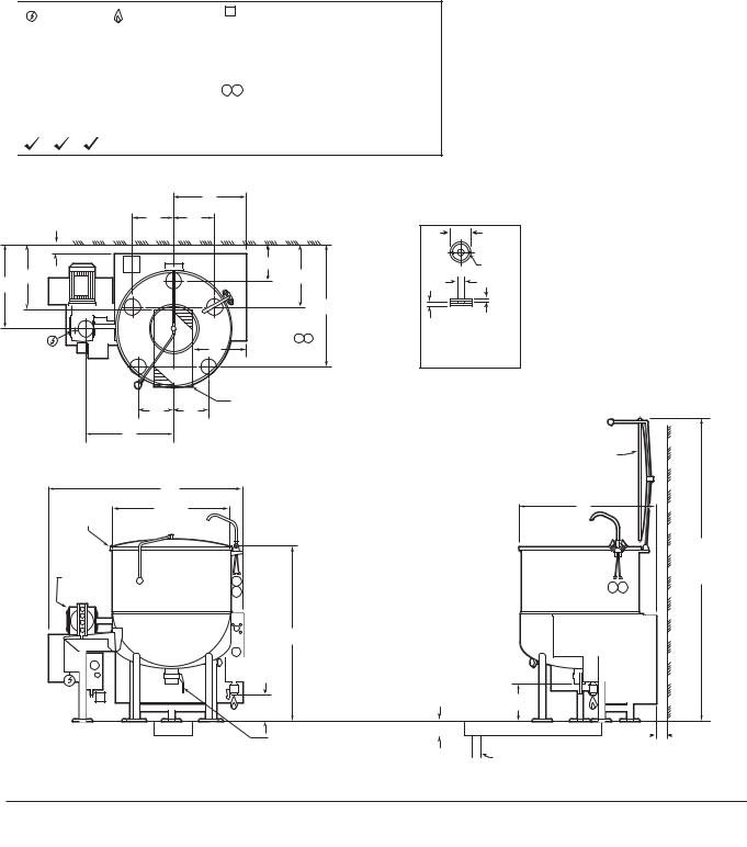
SPECIFICATION DRAWING - TILTING MODELS
ELECTRICAL |
GAS SUPPLY |
|
SUPPLY |
(PIPING 3/4" NPT) |
|
VOLTS: 208/240 |
TYPE: NAT or LP |
|
PHASE: 3 |
BTU PER CU. FT.: |
|
AMPS: |
15 |
1000 (NAT), 2500 (LP) |
|
|
|
FREQ: |
60 HZ |
SUPPLY PRESSURE: |
|
|
|
|
4" to 14" W.C. |
|
APPROVALS |
||
AGA CGA NSF |
BTU RATINGS: |
|
|
|
190,000 per hour |
|
|
|
A AIR SUPPLY (PIPING 1/2" NPT) |
APPROX. |
||
PRESSURE: |
|
SHIPPING |
|
|
WEIGHTS |
||
90 - 100 PSI |
|
|
|
(only required for optional 3" dia. |
60 GAL - |
||
piston draw-off valve) |
|
940 LBS. |
|
|
|
|
428 KG. |
H C HOT & COLD |
|
CLEARANCE |
80 GAL - |
WATER |
|
RIGHT: 3", LEFT: 3" |
1030 LBS. |
1/2" NPT CONNECTION |
|
469 KG. |
|
|
REAR: 3" |
||
|
100 GAL - |
||
40-60 PSI PRESSURE |
|
(ALLOW 12" SPACE |
|
|
1110 LBS. |
||
|
|
MINIMUM ON LEFT |
|
|
|
505 KG. |
|
|
|
SIDE FOR SERVICE) |
|
|
|
|
|
|
|
|
L |
|
|
|
|
3" REF. |
M |
M |
|
|
|
|
|
|
|
|
|
5 1/2" |
|
|
|
WALL |
|
|
|
|
|
|
|
|
|
|
|
|
5/8"Ø, |
|
|
|
|
|
10 3/8 |
|
2 HOLES |
|
|
|
|
|
|
ON |
|
|
|
Q |
|
|
18 3/8 |
|
4" B.C.D. |
|
|
K |
|
|
|
|
2" |
|
|
|
|
|
|
G |
3/8" |
|
|
|
|
|
|
|
|
|
|
|
|
|
|
|
1" (MAX. ADJUSTMENT) |
|
|
|
|
|
H C |
|
SOLID |
|
|
|
|
|
F |
|
FOOT DETAIL |
|
|
|
|
|
|
|
|
|
|
|
C |
|
|
|
|
|
|
|
L |
|
|
|
|
|
|
|
P |
P |
12" X 24" |
|
|
|
|
|
RECOMMENDED |
|
|
|
|
||
|
|
|
FLOOR DRAIN |
|
|
|
|
|
N |
|
|
|
|
|
|
|
|
|
|
|
|
SPRING ASSIST |
|
|
|
|
|
|
|
COVER (FULLY |
|
|
|
|
|
|
|
OPEN AT 90 ) |
WALL |
|
C |
|
|
|
|
|
|
|
|
|
|
|
|
|
|
|
A I.D. |
|
|
|
|
D |
|
RIM BAR |
|
|
|
|
|
|
|
|
|
|
|
|
|
|
E |
|
|
|
|
|
|
|
(COVER |
3 HP |
|
|
|
|
|
|
FULLY |
ELECTRIC |
|
|
H |
|
|
|
OPEN) |
MOTOR |
|
|
|
|
H C |
|
|
|
|
C |
|
|
|
||
|
|
|
|
|
|
|
|
|
|
|
B |
|
|
|
|
|
|
|
|
|
RECOMMENDED FLOOR |
|
|
|
|
|
|
|
SLOPE 1 INCH PER 4 FEET |
|
|
A |
|
|
8 3/4" |
|
6" RECOMMENDED |
13" |
|
|
|
|
|
|
|||
|
|
|
|
|
|
|
|
3" DIA. BUTTERFLY VALVE |
|
FLOOR DRAIN |
||||
|
|
|
|
|
3" MIN |
|
|
|
|
|
|
||
CLEARANCE
PIPE DRAIN RECOMMENDED
MINIMUM VALVE SIZE PLUS 1"
DIMENSIONS
MODEL |
A |
B |
C |
D |
E |
F |
G |
K |
L |
M |
N |
P |
Q |
HA-MKGL-60-CC |
29 1/2" |
48 1/4" |
50" |
36 1/2" |
83" |
13 1/8" |
34 5/8" |
23 7/8" |
19 1/8" |
10 3/32" |
24" |
9 3/4" |
17 7/8" |
HA-MKGL-80-CC |
33" |
51 3/4" |
58" |
39" |
90" |
14 7/8" |
35 15/16" |
24 5/8" |
20 7/8" |
11 17/32" |
26" |
9 3/4" |
18 5/8" |
HA-MKGL-100-CC |
35 1/2" |
54 1/4" |
60 1/2" |
40 3/4" |
96" |
16 1/8" |
37 1/8" |
25 1/4" |
22 1/8" |
12 3/4" |
27 1/4" |
11" |
19 1/4" |
NOTES: CLEVELAND RANGE EQUIPMENT IS BUILT TO COMPLY WITH APPLICABLE STANDARDS FOR MANUFACTURERS. INCLUDED AMONG THOSE APPROVAL AGENCIES ARE: UL, A.G.A., NSF, ASME/N.BD., CSA, CGA, ETL, AND OTHERS. INSTALLATIONS OF BACK FLOW PREVENTERS, VACUUM BREAKERS AND OTHER SPECIFIC CODE REQUIREMENTS ARE THE RESPONSIBILITY OF THE OWNER AND INSTALLER.
ALL VERTICAL DIMENSIONS SHOWN ARE MINIMUM. FEET ARE ADJUSTABLE TO +1" MAXIMUM. MANUFACTURER MUST BE NOTIFIED IF UNIT WILL BE OPERATING ABOVE 2000' ALTITUDE. CONSULT FACTORY FOR MANUFACTURED GAS.
Cleveland Range reserves right of design improvement or modification, as warranted.
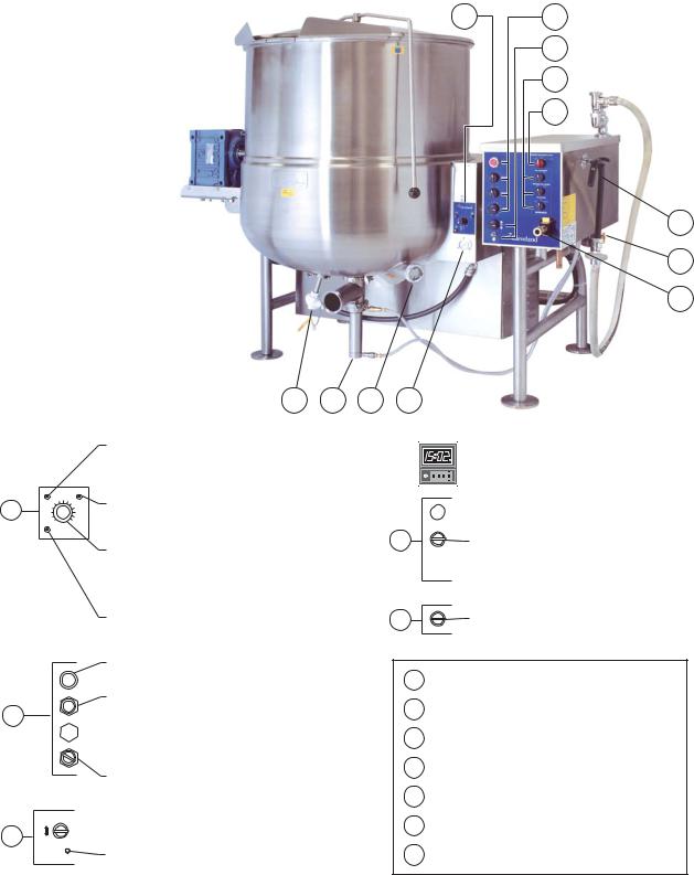
OPERATING INSTRUCTIONS
A |
1 2 3 4
B |
NOTE: |
|
Location of |
||
C |
switches may |
|
vary dependant |
||
on customers |
||
|
||
D |
specific options |
|
|
E |
7
5
6
Red Low Water Indicator Light
When lit, in the upright position, indicates kettle gas burner has cut out and unit requires more water. Occasional pulsing of this light is normal.
A |
Green Heat Indicator Light |
|
When lit, indicates gas burner is on; cycles on-off with |
||
|
||
|
solid state controls. |
Solid State Temperature Control Knob / On-Off Toggle Switch
Controls electrical power to kettle. and allows operator to select kettle heat increments from minimum, 1-10.
A setting of 7 or higher will boil water
Amber Ignition Failure Indicator Light
Indicates failure of heating system to ignite (Used prior to July 2004)
|
|
|
Water Meter Digital Counter (not shown) |
|
|
|
Location may vary dependant on customer's specific |
|
|
|
options |
0 |
1 |
2 |
3 |
Fill Interrupt Switch
 Interrupts water fill cycle
DPotable Fill Water Switch
Selects hot or cold water
 Fill Cycle Switch
Start/continue cycle switch
E |
Product Discharge Valve Switch |
Toggle momentary switch to desired valve opening |
Agitator Stop Button
Stops agitator in case of emergency
Agitator Start Switch
Starts agitator. Agitator power control switch must be ON
B
 Agitator Power Switch
Allows power to agitator. When not in use, turn control power OFF
Agitator Speed Control Switch
Turn clockwise until desired speed is reached
Power tilt control switch
 Tilts kettle for pouring; some kettles have manual hand tilt
C
Reset circuit breaker
Protects power tilt system from overload. Push to reset
1Temperature Sensor
Senses temperature of product
2Automatic Dump Valve
Empties kettle of either food product or wash water
Sight Glass
3For checking water level of kettle jacket
Vacuum /Pressure Gauge
4Indicates steam pressure inside steam jacket in PSI, as well as vacuum in inches of mercury
5Gas Shut-Off Valve Air Quick Connect
6Push yellow tab down to release air pressure before disconnecting air hose
7Kettle Filler Nozzle
General
WARNING: Do not attempt to operate this appliance during a power failure. Keep appliance and area free and clear of combustibles.
Before turning kettle on, ensure that following conditions exist:
•If you are cooking an egg or milk product, do not pre-heat kettle.
•The vacuum/pressure gauge needle is in green zone; if it is not and is in "vent air" zone, call your service agent to repair leak.
•The electrical service to kettle is turned on
NOTE: The kettle should be sanitized prior to the daily production run - see CLEANING INSTRUCTIONS .
Mixing ("AGITATOR ")
WARNING:
•Never add product to kettle while agitator is running.
•Do not put hands in kettle.
•Watch for loose clothing near agitator.
1.Turn "SPEED CONTROL" to "0".
2.Switch agitator to "ON".
3.Push agitator "START" to initiate mixing.
4.Turn "SPEED CONTROL" to desired mixing speed.
5.To stop mixing action, push agitator stop button.
NOTE: Mixing speed depends on the product consistency. The faster the mixing speed the more damage may be done to fragile product.
Heating (General Notes)
•The green light cycles on and off, indicating that burners are cycling to maintain set temperature.
•The red "low water" light should not be lit during operation. This light indicates that water level is critically low and that gas burners have automatically shut off. Before further use, refer to RESERVOIR FILL INSTRUCTIONS for adding distilled water.
•Occasional flashing of the red "low water" light is ok while kettle is heating.
Automatic Heating
1.Switch "CONTROLLER" to "ACTIVE".
2.Turn temperature control knob to "10".
3.Continually push function key "  " until "OFF" is displayed.
4.Push and hold key "  " or "
  " until desired temperature is set.
5.To Start: push function key
" " until "CtrL" is displayed.
6.Push down key "  ".
".
7.To Stop: push function key
" " until "OFF" is displayed.
8.Push down key "  ".
".
9.After closing discharge valve, place product in kettle.
Emptying the Kettle
1.To open automatic dump valve:
•Turn PRODUCT DISCHARGE VALVE switch clockwise to JOG TO OPEN. Release switch to the HOLD position when desired valve opening is achieved.
•To close valve, turn switch counterclockwise to CLOSED position.
2.To avoid splashing, slowly empty kettle contents into an appropriate container by partially opening dump valve.
NOTE: When pumping with a Metering Filling Station the speed of the agitator arm must be sufficient to suspend the heavier items in the mix in order to achieve an even distribution in your packaged items.
3.Immediately clean kettle as outlined in CLEANING INSTRUCTIONS on page.
Water Meter
1.Switch "POTABLE FILL WATER" to "HOT" or "COLD".
2.Set required volume by first pushing the "  " key until the digit you want to change is flashing in the lower display. Then use the "
  " key to change the value of the selected digit.
When all digits are set, press the "ENT" key.
Manual Heating
1.Switch "POWER" to "ON".
2.Turn temperature control knob to desired setting.
3.Switch "CONTROLLER" to "BYPASS".
3.Locate delivery spout over kettle.
4.Turn switch to "RESET". Delivery will start at "0" and stop at preset volume.
5.To stop delivery at any time, turn "FILL INTERRUPT" switch to " ● ".
4.After closing discharge valve, place product in kettle. 6. To complete delivery after interrupting, turn switch
"FILL CYCLE" to "CONTINUE".
CLEANING INSTRUCTIONS
CAUTION
SURFACES MAY
BE EXTREMELY HOT!
CARE AND CLEANING
Cooking equipment must be cleaned regularly to maintain its fast, efficient cooking performance and to ensure its continued safe, reliable operation. The best time to clean is shortly after each use (allow unit to cool to a safe temperature).
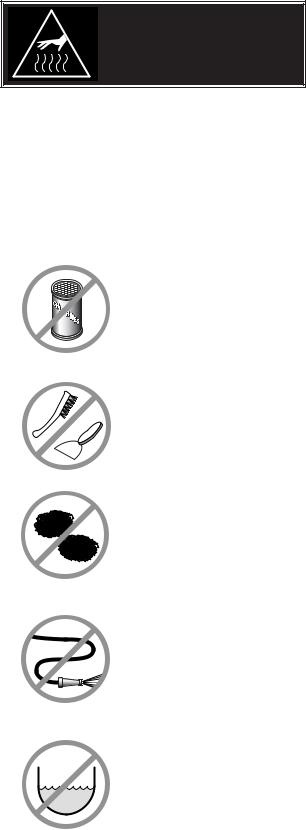
WARNINGS
|
Do not use detergents or |
|
cleansers that are chloride |
|
based or contain quaternary |
|
salt. |
|
Chloride Cleaners |
|
Do not use a metal bristle |
|
brush or scraper. |
|
Wire Brush & |
|
Steel wool should never be |
|
used for cleaning the stainless |
|
steel. |
|
Steel Pads |
|
Unit should never be cleaned |
|
with a high pressure spray |
|
hose. |
|
High Pressure |
|
Spray Hose |
|
Do not leave water sitting in unit |
|
when not in use. |
CLEANING INSTRUCTIONS
1.Turn unit off.
2.Remove drain screen (if applicable). Thoroughly wash and rinse the screen either in a sink or a dishwasher.
3.Prepare a warm water and mild detergent solution in the unit.
4.Remove food soil using a nylon brush.
5.Loosen food which is stuck by allowing it to soak at a low temperature setting.
6.Drain unit.
7.Rinse interior thoroughly.
8.If the unit is equipped with a Tangent Draw-Off Valve, clean as follows:
a)Disassemble the draw-off valve first by turning the valve knob counter-clockwise, then turning the large hex nut counter-clockwise until the valve stem is free of the valve body.
b)In a sink, wash and rinse the inside of the valve body using a nylon brush.
c)Use a nylon brush to clean tangent draw-off tube.
d)Rinse with fresh water.
e)Reassemble the draw-off valve by reversing the procedure for disassembly. The valve's hex nut should be hand tight only.
9.If the unit is equipped with a Butterfly Valve, clean as follows:
a)Place valve in open position.
b)Wash using a warm water and mild detergent solution.
c)Remove food deposits using a nylon brush.
d)Rinse with fresh water.
e)Leave valve open when unit is not in use.
10.Using mild soapy water and a damp sponge, wash the exterior, rinse, and dry.
NOTES
For more difficult cleaning applications one of the following can be used: alcohol, baking soda, vinegar, or a solution of ammonia in water.
Leave the cover off when the kettle is not in use.
For more detailed instructions refer to the Nafem Stainless Steel Equipment Care and Cleaning manual (supplied with unit).
Stagnant
Water
STAINLESS STEEL EQUIPMENT CARE AND CLEANING
(Suppied courtesy of Nafem. For more information visit their web site at www.nafem.org)
Contrary to popular belief, stainless steels ARE susceptible to rusting.
Corrosion on metals is everywhere. It is recognized quickly on iron and steel as unsightly yellow/orange rust. Such metals are called “active” because they actively corrode in a natural environment when their atoms combine with oxygen to form rust.
Stainless steels are passive metals because they contain other metals, like chromium, nickel and manganese that stabilize the atoms. 400 series stainless steels are called ferritic, contain chromium, and are magnetic; 300 series stainless steels are called austenitic, contain chromium and nickel; and 200 series stainless, also austenitic, contains manganese, nitrogen and carbon. Austenitic types of stainless are not magnetic, and generally provide greater resistance to corrosion than ferritic types.
With 12-30 percent chromium, an invisible passive film covers the steel’s surface acting as a shield against corrosion. As long as the film is intact and not broken or contaminated, the metal is passive and stain-less. If the passive film of stainless steel has been broken, equipment starts to corrode. At its end, it rusts.
Enemies of Stainless Steel
There are three basic things which can break down stainless steel’s passivity layer and allow corrosion to occur.
1.Mechanical abrasion
2.Deposits and water
3.Chlorides
Mechanical abrasion means those things that will scratch a steel surface. Steel pads, wire brushes and scrapers are prime examples.
Water comes out of the faucet in varying degrees of hardness. Depending on what part of the country you live in, you may have hard or soft water. Hard water may leave spots, and when heated leave deposits behind that if left to sit, will break down the passive layer and rust stainless steel. Other deposits from food preparation and service must be properly removed.
Chlorides are found nearly everywhere. They are in water, food and table salt. One of the worst chloride perpetrators can come from household and industrial cleaners.
So what does all this mean? Don’t Despair!
Here are a few steps that can help prevent stainless steel rust.
1.Use the proper tools.
When cleaning stainless steel products, use non-abrasive tools. Soft cloths and plastic scouring pads will not harm steel’s passive layer. Stainless steel pads also can be used but the scrubbing motion must be in the direction of the manufacturers’ polishing marks.
2.Clean with the polish lines.
Some stainless steel comes with visible polishing lines or “grain.” When visible lines are present, always scrub in a motion parallel to the lines. When the grain cannot be seen, play it safe and use a soft cloth or plastic scouring pad.
3.Use alkaline, alkaline chlorinated or non-chloride containing cleaners.
While many traditional cleaners are loaded with chlorides, the industry is providing an ever-increasing choice of non-chloride cleaners. If you are not sure of chloride content in the cleaner used, contact your cleaner supplier. If your present cleaner contains chlorides, ask your supplier if they have an alternative. Avoid cleaners containing quaternary salts; it also can attack stainless steel and cause pitting and rusting.
4.Treat your water.
Though this is not always practical, softening hard water can do much
to reduce deposits. There are certain filters that can be installed to remove distasteful and corrosive elements. To insure proper water treatment, call a treatment specialist.
5.Keep your food equipment clean.
Use alkaline, alkaline chlorinated or non-chloride cleaners at recommended strength. Clean frequently to avoid build-up of hard, stubborn stains. If you boil water in stainless steel equipment, remember the single most likely cause of damage is chlorides in the water. Heating cleaners that contain chlorides have a similar effect.
6.Rinse, rinse, rinse.
If chlorinated cleaners are used, rinse and wipe equipment and supplies dry immediately. The sooner you wipe off standing water, especially when it contains cleaning agents, the better. After wiping equipment down, allow it to air dry; oxygen helps maintain the stainless steel’s passivity film.
7.Never use hydrochloric acid (muriatic acid) on stainless steel.
8.Regularly restore/passivate stainless steel.
Recommended cleaners for specific situations
Job |
Cleaning Agent |
Comments |
Routine cleaning |
Soap, ammonia, |
Apply with cloth or sponge |
|
detergent, Medallion |
|
|
|
|
Fingerprints & smears |
Arcal 20, Lac-O-Nu |
Provides barrier film |
|
Ecoshine |
|
|
|
|
Stubborn stains & |
Cameo, Talc, Zud, |
Rub in direction of polish lines |
discoloration |
First Impression |
|
|
|
|
Grease & fatty acids, |
Easy-off, De-Grease |
Excellent removal on all finishes |
blood, burnt-on-foods |
It Oven Aid |
|
|
|
|
Grease & oil |
Any good |
Apply with sponge or cloth |
|
commercial detergent |
|
|
|
|
Restoration/Passivation |
Benefit, Super Sheen |
|
|
|
|
Review
1.Stainless steels rust when passivity (film-shield) breaks down as a result of scrapes, scratches, deposits and chlorides.
2.Stainless steel rust starts with pits and cracks.
3.Use the proper tools. Do not use steel pads, wire brushes or scrapers to clean stainless steel.
4.Use non-chlorinated cleaners at recommended concentrations. Use only chloridefree cleaners.
5.Soften your water. Use filters and softeners whenever possible.
6.Wipe off cleaning agent(s) and standing water as soon as possible. Prolonged contact causes eventual problems.
To learn more about chloride-stress corrosion and how to prevent it, contact the equipment manufacturer or cleaning materials supplier.
Developed by Packer Engineering, Naperville, Ill., an independent testing laboratory.
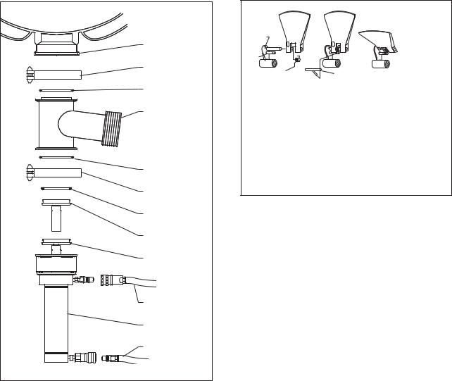
PRODUCT VALVE
Daily - clean product valve as follows:
KETTLE
KETTLE
OUTLET
CLAMP
0-RING
VALVE
TEE
0-RING
CLAMP
0-RING
CLOSED
POSTITION
OPEN
POSITION
AIR HOSE
AIR
CYLINDER
AIR HOSE
1.Open product valve.
2.Disconnect air hoses.
3.Remove air cylinder.
4.Remove valve tee.
5.Remove all O-rings.
6.Clean air cylinder, do not submerge in water. Wipe clean and sanitize.
7.Clean and sanitize tee and O-rings.
8.Grease and reinstall O-rings.
9.Reinstall tee to kettle outlet.
10.Reinstall air cylinder to bottom of tee.
11.Reconnect air hoses.
12.Close valve and check for alignment.
SCRAPER BLADES
To remove and clean scraper blades:
Scraper
blade 
Back stop
Pin A 
Pin B
Spring
Tool
Fig. 1 |
Fig. 2 |
Fig. 3 |
To Remove Scraper Blade
1.Insert tool that is provided as shown in Fig. 2.
2.Pull up on spring arm until arm clears groove in Pin B.
3.Spring is now disengaged, gently release spring to remove scraper blade.
To Install Scraper Blade
1.Slide scraper blade and spring onto Pin A as shown in Fig. 1.
2.Hook spring arm and pull up.
3.Using tool, engage spring arm into groove on Pin B. Scraper blade is now in place.
1.Remove scraper blades using the tool to release the spring from the retaining pin and sliding the blade off the shaft.
2.Place parts in a pan of warm water to soak.
3.Clean in a sink, using a warm water and mild detergent solution.
4.Rinse with fresh water.
5.Allow to dry thoroughly on a flat, clean surface.
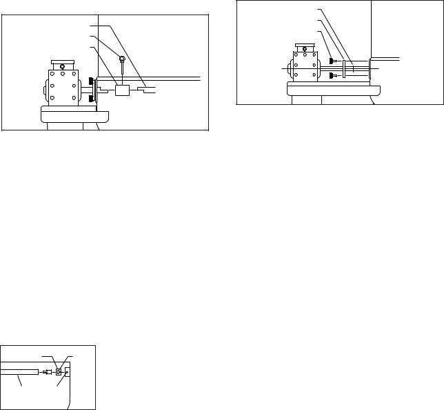
AGITATOR
To remove and clean agitator (two-person
job): |
Agitator shaft |
Pin |
Coupling |
Removing Agitator
1.Remove scraper blades.
2.Rotate agitator until pull pin is on top side.
3.Turn power OFF.
4.Pull pin out.
5.Slide coupling toward kettle wall, and carefully lift agitator pulling back to lift out.
6.Clean in a sink, using a warm water and mild detergent solution.
7.Rinse with fresh water.
AGITATOR BUSHING
With agitator out, remove bushing by:
1. Remove bushing
by turning 1/4 turn Bushing Slot and pulling away
from the kettle wall.
Agitator Retaining
Shaft pin
2. Clean, rinse and sanitize bushing and bushing mounting area.
3.Lubricate metal surfaces with food safe grease.
4.Install bushing by locating retaining pin and sliding bushing on.
5.Rotate to lock into position.
QUAD RING
To clean agitator quad ring:
Quad ring
Seal retainer plate
Retaining knobs
Cleaning Quad Ring
1.Remove retaining knobs.
2.Slide shaft seal retainer plate and quad ring away from kettle body.
3.Clean quad ring, shaft, and seal retainer plate with clean cloth.
4.Rinse with fresh.
5.Apply light coat of food safe grease to both sides of the quad ring.
6.Slide quad ring back into original position, making sure it does not twist.
7.Slide retainer plate back toward kettle, replacing retaining knobs.
8.Tighten with hand pressure only.
SERVICE PARTS
SCRAPER BLADES
ITEM NO. |
PART NO. |
DESCRIPTION |
QTY. |
1 |
1. |
KE54602 |
SCRAPER BLADE . . . . . . . . . . . . |
. . .7 |
|
2. |
KE54608 |
SPRING . . . . . . . . . . . . . . . . . . . . |
. . .7 |
|
3. |
KE01976 |
SPRING REMOVAL TOOL . . . . . |
. . . 1 |
|
|
|
|
2 |
3 |
AGITATOR SEAL ASSEMBLY
ITEM |
|
|
|
NO. |
PART NO. |
DESCRIPTION |
QTY. |
1. |
KE01911 |
RETAINING KNOBS . . . . |
. 3 |
2. |
KE54592 |
SEAL RETAINER PLATE . . |
1 |
3. |
FA05002-8 |
"O" RING . . . . . . . . . . . . . . |
1 |
4. |
KE54594 |
PIN . . . . . . . . . . . . . . . . . . |
1 |
5. |
KE54583 |
COUPLING . . . . . . . . . . . . |
1 |
6. |
KE54593 |
IDLER PIN . . . . . . . . . . . . |
1 |
7. |
KE54590 |
BUSHING . . . . . . . . . . . . . |
1 |
1 |
2 |
3 |
4 |
5 |
6 |
7 |
Agitator |
Shaft |
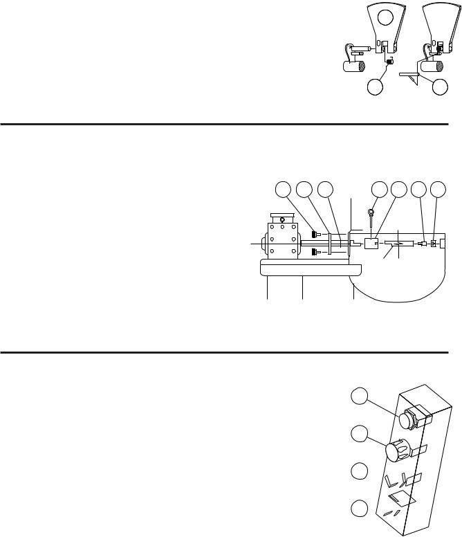
OPERATING CONTROLS |
1 |
ITEM NO. PART NO. DESCRIPTION |
QTY. |
1. |
KE54531 |
AGITATOR STOP . . . . . . . . . . . . . . . . . . . . . . |
1 |
2. |
KE54530 |
AGITATOR START . . . . . . . . . . . . . . . . . . . . . |
1 |
3. |
KE54529 |
POWER ON/OFF SWITCH . . . . . . . . . . . . . . . |
1 |
4. |
KE54532 |
SPEED CONTROL . . . . . . . . . . . . . . . . . . . . . |
1 |
2
3

4 


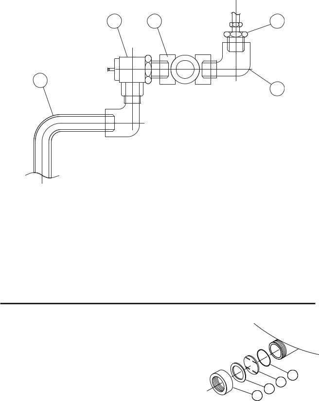
PRESSURE RELIEF ASSEMBLY
4 |
3 |
1 |
5
2
ITEM NO. |
PART NO. |
DESCRIPTION |
QTY. |
|
1. |
FA05049 |
MALE CONNECTOR, 1/2" PIPE - 1/4" TUBE . . . . . . . . . . . . . . . . . . . . . . . . . |
. . .1 |
|
2. |
FI00151 |
STREET ELBOW, 1/2" . . . . . . . . . . . . . . . . . . . . . . . . . . . . . . . . . . . . . . . . . . . |
. .2 |
|
3. |
FI00178 |
TEE, 1/2" FPT, BRASS . . . . . . . . . . . . . . . . . . . . . . . . . . . . . . . . . . . . . . . . . . . |
. .1 |
|
4. |
KE54941-5 |
SAFETY VALVE, 50 |
PSI, 1/2" (NORTH AMERICA) . . . . . . . . . . . . . . . . . . . . . |
. .1 |
|
KE54941-31 |
SAFETY VALVE, 50 |
PSI, 1/2", (EUROPE) . . . . . . . . . . . . . . . . . . . . . . . . . . . . |
. .1 |
5. |
KE54223 |
BLOW DOWN TUBE . . . . . . . . . . . . . . . . . . . . . . . . . . . . . . . . . . . . . . . . . . . . |
. .1 |
|
SIGHT GLASS |
|
|
|
ITEM ON. |
PART NO. |
DESCRIPTION |
QTY. |
1. |
KE50955 |
RETAINING COVER . . . . . . . |
. 1 |
2. |
KE52871 |
WASHER . . . . . . . . . . . . . . . |
. 1 |
3. |
KE51053-1 |
SIGHT GLASS . . . . . . . . . . . |
. 1 |
4. |
FA05002-30 |
”O” RING . . . . . . . . . . . . . . . |
. 1 |
HI
LO
4
3
2
1
 Loading...