


ClevelandRange
COUNTER TYPE
CONVECTION STEAMER
SERVICE
MANUAL
Model CET-16
Printed March, 1990
Cleveland Range
UNITED STATES |
CANADA |
1333 East 179th St., Cleveland, Ohio 44110 |
8251 Kelle St. · Concord, Ontario, Canada L4K 1Z |
Phone: (216) 481-4900 • Telex: 98-0546 • |
Phone: (416) 660-4747 • Fax: (416) 660-4492 |
Fax: (216) 481-3782 |
Toll Free: 1-800-387-3562 (in Canada only) |
Toll Free: 1-800-338-2204 (in U.S.A only) |
|
|
CET-16 Service Manual Page 1 |
Table of Contents |
|
CHAPTER |
PAGE |
CHAPTER 1-PRODUCT IDENTIFICATION |
1 |
MODEL NUMBER |
1 |
SERIAL NUMBER |
1 |
PRODUCT INFORMATION PLATE |
1 |
CHAPTER 2 INSTALLATION INSTRUCTIONS |
3 |
INTRODUCTION |
3 |
INSTALLATION POLICIES |
3 |
INSTALLATION OVERVIEW |
4 |
PREPARATION FOR INSTALLATION |
6 |
Water Quality Requirements |
6 |
SteamCraft Operating I Location |
7 |
Electric Power Line |
9 |
Water Supply Lines |
10 |
Free Air Vented Drain Lines |
11 |
INSTALLATION INSTRUCTIONS |
13 |
Unpacking and Inspection |
13 |
Shipping Damage Instructions |
14 |
Assembly |
14 |
Install The Steam Generator Cover |
14 |
Install The Fan Guard |
14 |
Install The Slide Racks |
15 |
Install The Water Strainer |
15 |
Position and Level SteamCraft V |
16 |
Connect Electrical Line |
17 |
Canadian Wiring Considerations |
18 |
Connect Untreated Water Line |
18 |
Connect Treated Water Line |
20 |
Connect Drain Line |
20 |
Final Setup And Checkout |
21 |
Setup |
21 |
TIMED Test -1 Minute |
22 |
MANUAL Test |
23 |
TIMED Test - 10 Minutes |
23 |
FUNCTION TEST Before S/N WC 9018-90A-05 |
24 |
Flow, Leak, and Flood Test |
24 |
Door Switch Test |
26 |
TIME and Temperature Tests |
26 |
FUNCTION TEST After S/N WC9018-90A-05 |
28 |
Flow, Leak, and Hood Test |
28 |
Door Switch Test |
30 |
TIME and Temperature Tests |
30 |
Printed 4/90
Page ii |
CET-16 Service Manual |
|
CHAPTER |
Table of Contents |
PAGE |
CHAPTER 3. OPERATION |
33 |
|
INTRODUCTION |
33 |
|
OPERATIONAL SAFETY |
33 |
|
CONTROL PANEL Before S/N WC 9018-90A-05 |
34 |
|
CONTROL PANEL After S/N WC 9018-90A-05 |
36 |
|
DRAIN VALVE |
38 |
|
TIMED MODE Before S/N WC 9018-90A-05 |
39 |
|
TIMED MODE After S/N WC 9018-90A-05 |
39 |
|
MANUAL MODE Before S/N WC 9018-90A-05 |
40 |
|
MANUAL MODE After S/N WC 9018-90A-05 |
40 |
|
THERMOSTATIC TIMER COMPENSATION |
40 |
|
CONTROL PANEL WARNINGS |
41 |
|
START-UP AND PREHEAT |
41 |
|
COOKING |
|
42 |
TIMED Cooking |
43 |
|
MANUAL Cooking |
43 |
|
SHUT DOWN (At end of day or shift) |
43 |
|
CHAPTER 4 PREVENTATIVE MAINTENANCE AND TROUBLSHOOTING |
47 |
|
INTRODUCTION |
47 |
|
MAINTENANCE RECORDS |
47 |
|
DAILY MAINTENANCE |
47 |
|
WEEKLY MAINTENANCE |
48 |
|
YEARLY MAINTENANCE |
48 |
|
STEAM GENERATOR DESCALING PROCEDURE |
49 |
|
TROUBLESHOOTING NOTES |
52 |
|
CHAPTER 5 ELECTRICAL SYSTEM |
55 |
|
OVERVIEW |
|
55 |
PRIMARY CIRCUIT |
55 |
|
Heater Element Testing |
58 |
|
120 VAC: CIRCUITS |
58 |
|
Power Circuits |
58 |
|
Control Circuits |
59 |
|
Water Fill Solenoid Valve |
59 |
|
Condenser Spray Solenoid Valve |
60 |
|
Steamer Ready Conditions |
60 |
|
Front Contactor (3 pole) |
60 |
|
Rear Contactor (3 pole) |
60 |
|
LOW VOLTAGE CIRCUITS and CONTROL BOARD |
61 |
|
CON 1 Connections |
61 |
|
CON 2 Connections |
61 |
|
Printed 4/90
CET-16 Service Manual Page iii
CHAPTER |
Table of Contents |
PAGE
Color Coded Wiring Harness |
61 |
Printed Circuit Boards |
62 |
Door Sensor |
62 |
Membrane Switch |
62 |
Compartment Temperature Switch |
63 |
Time/Temperature Circuit - Troubleshooting |
64 |
WATER LEVEL PROBES |
64 |
Set Point |
64 |
Water Level Control Testing |
65 |
Flood Probe Control Circuit |
65 |
Water Level Probe Control Circuit |
65 |
Low Water Level Control Circuit |
66 |
TEMPERATURE CONTROL CIRCUITS |
67 |
Generator Temperature Control Circuit |
68 |
Drain Temperature Circuit |
68 |
Thermistor Testing |
69 |
CHAPTER 6 ILLUSTRATED PARTS LISTS |
71 |
INTRODUCTION |
71 |
WIRING AND SCHEMATIC DIAGRAMS |
'71 |
Printed 4/90

Page 0 CET-16 Service Manual
Figure 1-1. SteamCraft V Counter Type Convection Steamer
Printed 4/90
CET-16 Service Manual Page 1
CHAPTER 1. PRODUCT IDENTIFICATION
Cleveland Range, Inc. identifies products by two numbers: a model number and a serial number. The model number identifies the product characteristics. The serial number identifies the individual unit
MODEL NUMBER
SteamCraft V steamers are identified by model number CET-16. Each character of the model number identifies a characteristic of the steamer. The SteamCraft V is a Convection steamer, Electric powered, and Table mounted with an input energy rating of 16.5 KW. This manual covers all standard features of model CET-16 SteamCraft V steamers. Figure 1-1 illustrates the SteamCraft V and identifies the major components.
SERIAL NUMBER
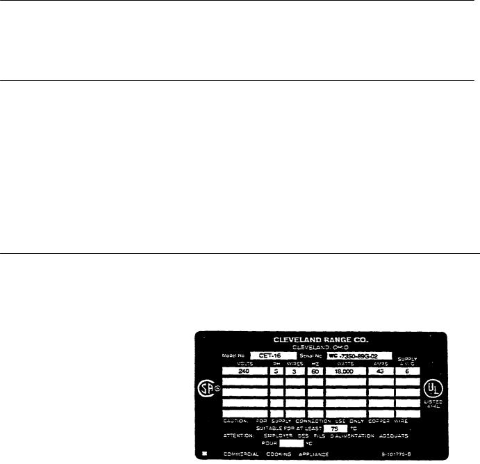
During manufacture, SteamCraft V's are assigned serial numbers. A typical SteamCraft V serial number is: WC-7350-89G-02 The left half of the number carries design information. The right half of the number contains the manufacturing date and the unit of the manufacturing lot. The date of our sample number is July, 1989:89= 1989, G=July. 02=the second unit of the manufacturing lot.
Serial numbers are used when explaining differences in design, parts, or operation among units with the same model number. For example: a particular part is used on all CET-16 steamers, with serial numbers before WC-7350-89G-02, and a different part is used on CET-16 steamer WC-7350-89G-02 and all those manufactured after it
Presently, there are no significant design, parts, or operating differences among model CET-16 SteamCraft V steamers.
PRODUCT INFORMATION PLATE
The serial number and model number for each are listed on the product information tag secured to the left side of the steamer. Refer to figure 1-1 for the location of this tag. Figure 1-2 illustrates a typical SteamCraft product information plate. Note that the power and wiring requirements are also listed.
Figure 1-2. SteamCraft V Product Information Plate
Printed 4/90

CET-16 Service Manual Page 3
CHAPTER 2. INSTALLATION INSTRUCTIONS
INTRODUCTION
This chapter is a guide for qualified, professional plumbers and electricians installing the SteamCraft V steamer. This guide does not include procedures and precautions in the common domain of licensed plumbers and electricians, or experienced food service equipment installers. The instructions in this chapter must be used in conjunction with a thorough understanding of the Basic Plumbing Code of the Building Officials and Code Administrators International, Inc. (BOCA) and the Food Service Sanitation Manual of the Food and Drug Administration (FDA).
Before starting installation, the owner and the installer should read through this chapter and thoroughly understand and agree upon:
•The installation policies of Cleveland Range, Inc. as stated in Installation Policies
•An installation plan based on Installation Overview and Preparation For Installation
•Responsibility for feed water quality and its testing as described in Preparation for Installation, Water Quality
WARNING
DEATH, INJURY, AND EQUIPMENT DAMAGE could result from improper installation of the SteamCraft V, or from installation of a unit damaged
during shipment or storage. Either of these conditions could also void the equipment warranty.
DO NOT INSTALL a SteamCraft V suspected of damage.
Install the SteamCraft V according to the policies and procedures outlined in this manual
INSTALLATION POLICIES
•The SteamCraft V must be installed by qualified plumbing and electrical personnel, working to all applicable national and local codes.
Equipment installation must comply with the Basic Plumbing Code of the Building Officials and Code Administrators International Inc. (BOCA) and the Food Service Sanitation Manual of the Food and Drug Administration (FDA).
•This equipment is designed and manufactured to comply with applicable standards for manufacturers. Included among those certification agencies which have approved the safety of the
Printed 4/90

Page 4 CET-16 Service Manual
equipment design and construction are: UL, A.G.A., ASME/N. Bd., NSF, CSA, CGA, ETL, and others.
• This equipment is designed and certified for safe operation only when permanently installed in accordance with local and/or national codes. Many local codes exist, and it is the responsibility of the owner and installer to comply with these codes.
• In no event shall the manufacturer assume any liability for damage or
|
injury resulting from installations which are not in strict compliance with |
||
|
the Installation Instructions and the codes cited above. Specifically, the |
||
|
manufacturer will not assume any liability for damage or injury resulting |
||
|
from improper installation of equipment, including, but not limited to, |
||
|
temporary or mobile installations. |
||
INSTALLATION OVERVIEW |
Schematic Installation Diagram, figure 2-1, illustrates the various |
||
|
electrical, water, and drain lines that must be connected to the SteamCraft |
||
|
V. These lines can be constructed and connected to the SteamCraft V |
||
|
easily and without delay if the various construction and installation tasks |
||
|
are performed a planned sequence. Table 2-1 summarizes these tasks |
||
|
and lists them in a recommended sequence. The Installation Checklist |
||
|
outlines the overall installation process; the instructions referenced in the |
||
|
table provide details Installation requirements may vary from site to site; |
||
|
adapt the checklist accordingly. |
||
|
|
|
|
Table 2-1. Installation Check List |
|
|
|
TASK |
PAGE REFERENCE |
COMPLETED |
|
Preparation |
6 |
|
|
Test SteamCraft V Water Supply |
6 |
|
|
Install Water Treatment System |
7 |
|
|
Select SteamCraft V location |
7 |
|
|
Install Power Line |
9 |
|
|
Extend Water Line(s) |
10 |
|
|
Extend Drain Line |
11 |
|
|
Installation |
|
|
|
Unpack and Inspect SteamCraft V |
13 |
|
|
Assemble Parts Shipped Loose |
14 |
|
|
Position and Level SteamCraft V |
16 |
|
|
Connect Electrical Line |
17 |
|
|
Connect Untreated Water Line |
18 |
|
|
Connect Treated Water Line |
20 |
|
|
Connect Drain Line |
20 |
|
|
Perform Setup and Checkout |
21 |
|
|
Perform Function Test |
23 |
|
|
Printed 4/90
CET-16 Service Manual Page 5
Figure 2-1. Schematic Installation Diagram
1.Electrical conduit access to terminal block inside back cover.
•Canadian steamers are supplied with six feet of flexible conduit for compliance with Canadian Standards Association.
2.A separate disconnect switch with fuses sized to line amps (see Table 2-3) MUST be installed for each steamer.
•Furnished and installed by others.
3.The steamer MUST be electrically grounded by the Installer.
4.Untreated cold water connection (1/4'' NPT).
•Steam Generator and Condenser supply for
units without water treatment system.
•Condenser supply for units with SteamerGard water treatment system.
5.Access for treated cold water connection.
•Steam Generator supply for units with SteamerGard water treatment systems.
•Requires additional parts and installation by authorized service representative.
6.Drain outlet connection with 1-1/4" NPT.
•Outlet extension connects to drain outlet.
•Outlet extension line has free air vented connection to floor drain.

Page 6 CET-16 Service Manual
PREPARATION FOR INSTALLATION
Before unpacking and positioning the SteamCraft V, select and prepare the installation site. This section of Chapter 2 details selection of the SteamCraft operating location, and preparation of that site with power, water, and drain lines.
Water Quality Requirements
CAUTION
VOID WARRANTY
The use of steam generator feed water not within the limits specified in this section of the manual could void equipment warranties.
As with any steam generating equipment, water quality is a critical factor in SteamCraft V performance. If Seed water is tow in Total Dissolved Solids (TDS) and free of particulate manner, the steam generator, heating elements, and valves of the SteamCraft V will give years of trouble-free service with a minimum of maintenance .
In some areas, even potable tap water contains a variety of impurities that can cause costly problems in steam generating equipment. Of primary concern are mineral salts, IPS, which remain behind as line or scale deposits after the water has boiled away as steam. These deposits have caused a variety of components to fail, including heating elements, probes, and solenoid valves. Of equal importance is the toss of energy efficiency due to line or scale buildup. In these areas, either a SteamerGard water treatment system must be installed, or time frequency of maintenance, cleaning, and descaling must be increased.
It is critical to know the quality of the feed water before starting construction of the water supply fines. If a SteamerGard water treatment system must be installed to achieve acceptable water quality, it should be installed before running the water supply lines to the SteamCraft V.
Contact a local water treatment specialist for an on-the-premises water analysis. The recommended minimum feed water quality requirements for the SteamCraft V are listed in table 2-2.
• If analysis shows that the supply water is within the required limits, a single water connection can be installed as illustrated in figure 2-2.
•If analysis shows that the supply water is NOT within the required limits, a SteamerGard water treatment system and two water supply lines must be installed as illustrated in figure 2-3.
•If analysis shows that the supply water is NOT within the required limits,
and it is not possible to install a SteamerGard water treatment; plan on increasing the frequency of maintenance, cleaning, and descaling beyond that recommended in the maintenance schedule
(Chapter 4, page 37).
Printed 4/90
CET-16 Service Manual Page 7
Table 2-2. Minimum Feed Water Quality Requirements
Total Dissolved Solids |
less than 60 pans per million |
Silica |
less than 13 pans per million |
Alkalinity |
less than 20 pans per minion |
pH factor |
greater than 7.5 |
SteamCraft V Operating Location
When selecting an operating location for the SteamCraftV, observe the following criteria.
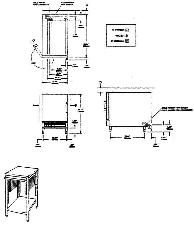
•The SteamCraft V takes up a minimum of counter space. Figure 2-4 illustrates the dimensions and clearances required. The 3'' clearance at the rear includes spacing for the water inlet strainer and fittings, and the maximum size (2" NPT) drain fittings.
•Figure 2-4 illustrates a left hand door hinge. A right hand door hinge (model # DHR-5) is also available for the SteamCraft V.
Printed 4/90
Page 8 CET-16 Service Manual
INSTALLATION CLEARANCES
A - 2"
B - 2"
C - 3"
D - 3"
E - 4"
Figure 2-4. SteamCraft V Dimensions and Clearances
•Note in figure 2-4 that a3" clearance is required above the SteamCraft V. Do not store articles on top of the unit.
•The SteamCraft V weighs approximately 120 pounds. The counter
area selected must be capable of supporting an operational weight of approximately 150 pounds to include the weight of water and food.
• The SteamCraft V has capacity for five 12" x 20" x 2.5" Cafeteria Pans (model # SP-25 or PP-25). Convenient storage for these pans and their alternates should be considered when selecting the operating location.
If a satisfactory counter location is not available consider using a model ES-1827 Equipment Stand. This stand, illustrated in figure2-5, is specifically designed for the SteamCraft V, and meets the above criteria.
Figure 2-5. Equipment Stand
Printed 4/90
CET-16 Service Manual Page 9
Electric Power Line
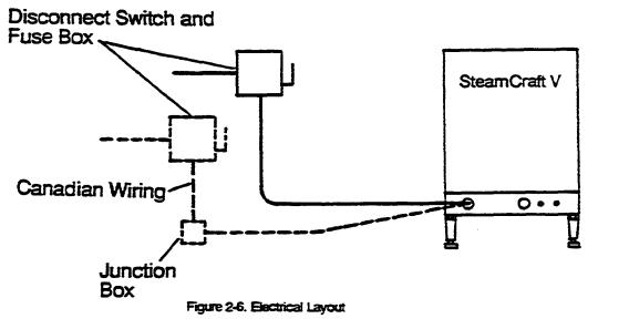
Furnishing and installing the electrical power Iines, switches, fuse boxes, connectors and their accessories is the responsibility of the owner and/or installer. Figure 2-6 illustrates an electrical layout recommended by Cleveland Range. When installing the electrical power lines and accessories, observe the following instructions.
1.In the United States, install the electrical power lines in accordance with local codes and/or the National Electric Code, ANSI/NFPA No. 70-1990 (USA).
2.In Canada, install the electrical power lines in accordance with local codes and/or the Canadian Electrical Code, CSA Standard C22.1 (Canada).
3.Install the proper size disconnect switch, circuit breaker or fuses, and wire and conduit to conform to all local codes and the national codes cited above. See table 2-3 for wire requirements.
Table 2-3. Minimum Wire Requirements
LINE |
KILO |
LINE |
WIRE |
VOLTAGE |
WATTS |
AMPS* |
GAUGE** |
208 |
16.7 |
46 |
6 |
220 |
153 |
40 |
6 |
240 |
18.0 |
43 |
6 |
380/220 |
153 |
23 |
10 |
415/240 |
18.0 |
25 |
10 |
440 |
153 |
20 |
10 |
480 |
18.0 |
22 |
10 |
*All 3 Phase
**Use copper wire rated for 75° C.
Printed 4/90

Page 10 CET-16 Service Manual
Water Supply Lines
Printed 4/90
4.Install a separate disconnect switch and fuses sized to line amps (see Table 2-3). The fuses may be an integral part of the disconnect switch or in a separate fuse box.
5.There should be a sufficient length of flexible conduit between the SteamCraft V connector and the wall so the unit can be moved for service.
•Canadian steamers arc supplied with six feet of flexible conduit for compliance with Canadian Standards Association. The electrical supply line must end in a junction box behind the steamer for connection of the flexible cable from the steamer.
6.Each steamer MUST be electrically grounded by the installer.
7.The characteristics of the electric power supply must match the power requirements specified on toe SteamCraft V product identification plate. The plate is located on the left side of the unit (refer to figure 1- 1).
8.All SteamCraft V's are wired for 3 phase only, and are not convertible to single phase.
Furnishing and plumbing the water supply lines is the responsibility of the owner and/or installer. Figures 2-2 and 2-3 illustrate plumbing layouts recommended by Cleveland Range. When installing water supply fines, observe the following instructions.
1.Always connect a COLD water supply to the condenser/steam generator connection (item 4, figure 2-1). If hot or warm water is supplied to
this connection, the steam condenser in the SteamCraft V will not work
2.Supply water pressure must be a minimum dynamic pressure of 35 psi (2.4 kg/cm2) and a maximum static pressure of 60 psi (4.1 kg/cm2).
3.The recommended size for the water supply lines is 1/4'L.P.S. This is the size of toe lines in the SteamCraft V. If larger lines are used, a pressure reducer must be installed in the supply line to maintain the
pressure specified in #2, above.
4.NSF requires the installation of a check-valve in accordance with and as required by local plumbing codes.
5.When a water treatment system is not installed, Cleveland Range recommends the plumbing layout illustrated in figure 2-2.
6.When a water treatment system is installed, Cleveland Range recommends the plumbing layout illustrated in figure 2-3.
•The water supply to the condenser/steam generator connection (item 4, figure 2-1) can be untreated.
•The treated water supply is connected to the steam generator only connection (item 5, figure 2-1).
•The steam generator only connection requires plumbing changes inside the SteamCraft V. These changes can be made only by an authorized service representative.

CET-16 Service Manual Page 11
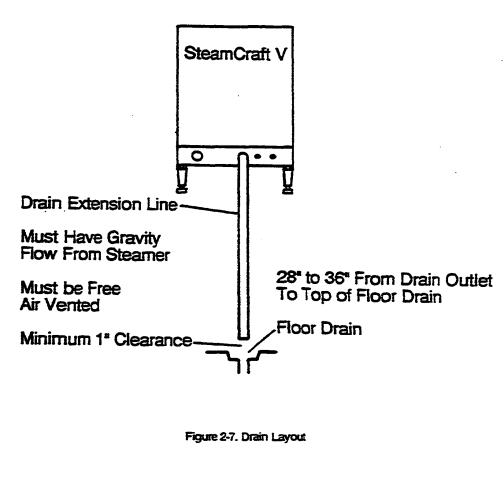
Free Air Vented Drain Lines
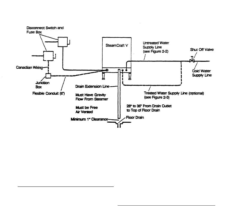
The drain outlet discharges exhaust steam and hot condensate from the steamer. This discharge is usually under pressure. The drain outlet MUST be free air vented to disburse the pressure, and avoid creating a back pressure or a vacuum within the SteamCraft V.
•Backpressure will cause steam and hot water leakage around the door.
•A vacuum will implode the steamer.
Furnishing and plumbing the drain lines is the responsibility of the owner and/or installer. Figure 2-7 illustrates a drain layout recommended by Cleveland Range. Observe the following instructions to determine the pipe size, the number of fittings required, and the layout of the drain line path.
 Printed 4/90

Page 12 CET-16 Service Manual
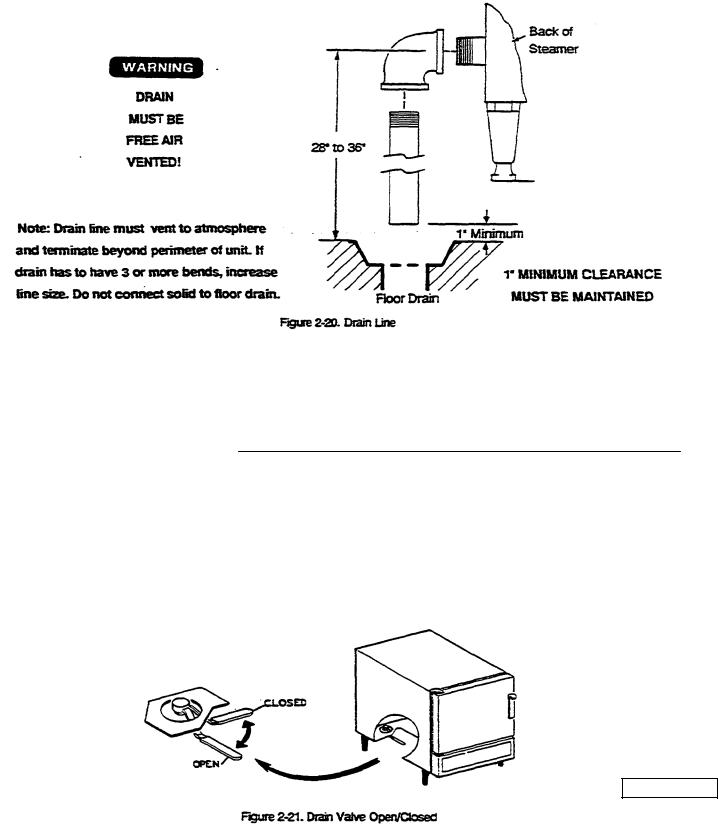
WARNING
DEATH, INJURY, AND EQUIPMENT DAMAGE could result from improper installation of the drain outlet lines.
Improper installation of these lines could void the SteamCraft V warranty. The following restrictions are critical to the safety of personnel and equipment, and must not be violated under any circumstances.
Do not run the drain line into PVC pipe, or any other drain material that cannot sustain 180° F.Do not connect more than two pieces of equipment to one common drain line.
Do not connect the drain outlet extension line directly to a floor drain or sewer line without free air venting.
1.The drain lines must be installed in compliance with the Basic Plumbing Code of the Building Officials and Code Administrators International, Inc. (BOCA), and the Food Service Sanitation Manual of the Food and Drug Administration (FDA).
2.The pipe size used to extend the drain outlet to an open drain is determined by the cumulative length of pipe and/or number of elbow fittings required to reach the open drain.
•If the drain outlet extension requires six feet or less of pipe, and no more than two elbows are required, use 1/4'' pipe and
fittings.
•If the drain outlet extension requires six to twelve feet of pipe, or requires more than three elbows, use 2" pipe and fittings.
3.The drain line must have a gravity flow from the SteamCraft V drain outlet to the floor drain.
4.There must be a minimum of one-inch clearance between the end of the drain line and the top of the floor drain to assure free air venting.
5.When assembling the pipe and fittings of the drain line, apply a hardening type pipe sealant to the threads, and tighten them together FINGER TIGHT ONLY. DO NOT USE A WRENCH.
INSTALLATION INSTRUCTIONS
After selecting and preparing the SteamCraft V operating location, the steamer can be unpacked, positioned, and installed. This section of Chapter 2 details inspecting, positioning, and connecting the SteamCraft V to the power, water, and drain lines already prepared. After final setup and testing, the SteamCraft V is ready for years of reliable operation.
Printed 4/90
CET-16 Service Manual Page 13
WARNING
DEATH, INJURY, AND EQUIPMENT DAMAGE could result from installation of a unit damaged during shipment or storage. Equipment damaged during shipment or storage is not covered under warranty.
DO NOT UNPACK A DAMAGED SHIPPING CARTON.
DO NOT INSTALL a SteamCraft V suspected of damage.
1.Before unpacking the shipping carton visually inspect it for damage.
•If the shipping carton appears damaged, do not open the carton. Refer to the Shipping Damage Instructions below.
•If the shipping carton is undamaged, open it and remove the SteamCraft V.
2.Slit the four corners of the carton and peel carton sides away from the SteamCraft V.
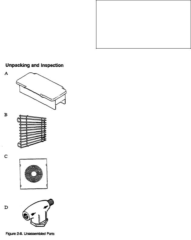
3.Open the door of the SteamCraft V, and remove the package of
unassembled parts. This package contains the four parts illustrated in figure 2-8 Check that all four parts have been included in the package.
A.Steam Generator Cover
B.Two Slide Racks
C.Fan Guard
D.Water Strainer
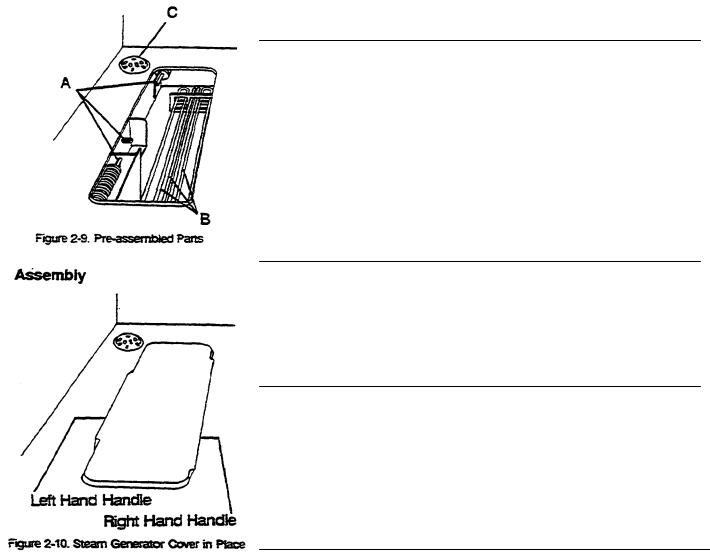
4.When the unassembled parts package is removed, several preassembled parts can be seen inside the unit. Refer to figure 2-9. Do
not attempt to remove these parts.
A.Water Level Probes
B.Heater Elements
C.Drain Screen
5.Inspect the SteamCraft V and unassembled parts for damage or loss.
•If there is damage or parts are lost, refer to the Shipping Damage Instructions below.
•If all items are accounted for and undamaged, proceed to Assembly and install the unassembled parts listed in step 3.
Printed 4/90
CET-16 Service Manual |
Page 14 |
Shipping Damage Instructions
If shipping damage to the SteamCraft V is discovered or suspected, observe the following guidelines in preparing a shipping damage claim.
•Write down a description of the damage or the reason for suspecting damage as soon as it is discovered. This will help in filling out the claim forms later.
•As soon as damage is discovered or suspected, notify the carrier that delivered the shipment.
•Arrange for the carrier's representative to examine the damage.
•Fill out all appropriate claims forms and have the examining carrier sign and date each form.
Parts shipped unassembled (figure2-8) can be assembled before or after the SteamCraft V is connected to the electric power, water supply, and drain lines. If these parts are to be stored during the connection procedures, place them back in their shipping box place the box back inside the steamer, and dose the steamer door. Otherwise, assemble these parts according to the following instructions.
Install The Steam Generator Cover
1.Refer to figure 2-10, and hold the steam generator cover with the short handle to the left and the long handle to the right. The printing on the top (of the cover should be right side up (Descale With Kit P/N 101751 - Remove Daily To Clean).
2.Keeping the cover level, place the right leg of the cover against the right side of the steam generator body and the left leg against the protective baffle on the left side.
3.Lower the cover into place over the steam generator opening.
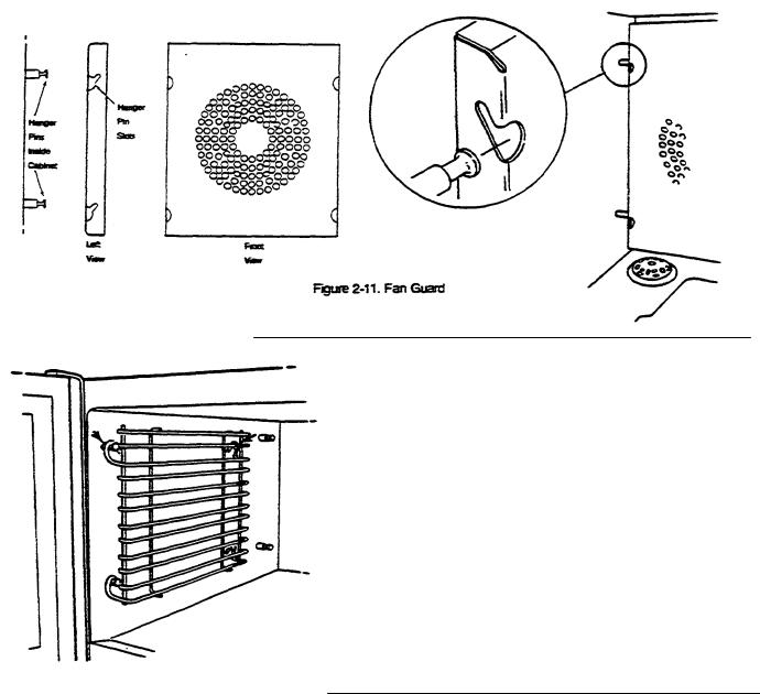
Install The Fan Guard
1.Refer to figure 2-11 and hold the fan guard so the hanger pin slots are pointing up and towards the back of the guard.
2.Slide the right side of the guard past the hanger pins, and into the right rear comer of the steamer compartment.
3.Swing the left side of the guard past the hanger pins, and into the left rear corner of the steamer compartment. The guard will cover the fan.
4.Holding both sides of the guard, lift it to aline the hanger slots with the large hanger pins at the back of the steamer.
5.Pull the fan guard forward and down to slide the hanger slots over the hanger pins.
Printed 4/90
CET-16 Service Manual Page 15
Install The Slide Racks
1. Refer to figure 2-12. Each rack has four loops: two on top and two on the bottom. Hold one slide rack so the ends of the hanger loops are pointing down.
2. Slide one rack into the steamer compartment with the hanger loops toward one side of the compartment
3.Hoop the two top loops over the top pins, then hook the bottom loops over the two bottom pins.
4.Repeat steps 1 through 3 for the other rack.
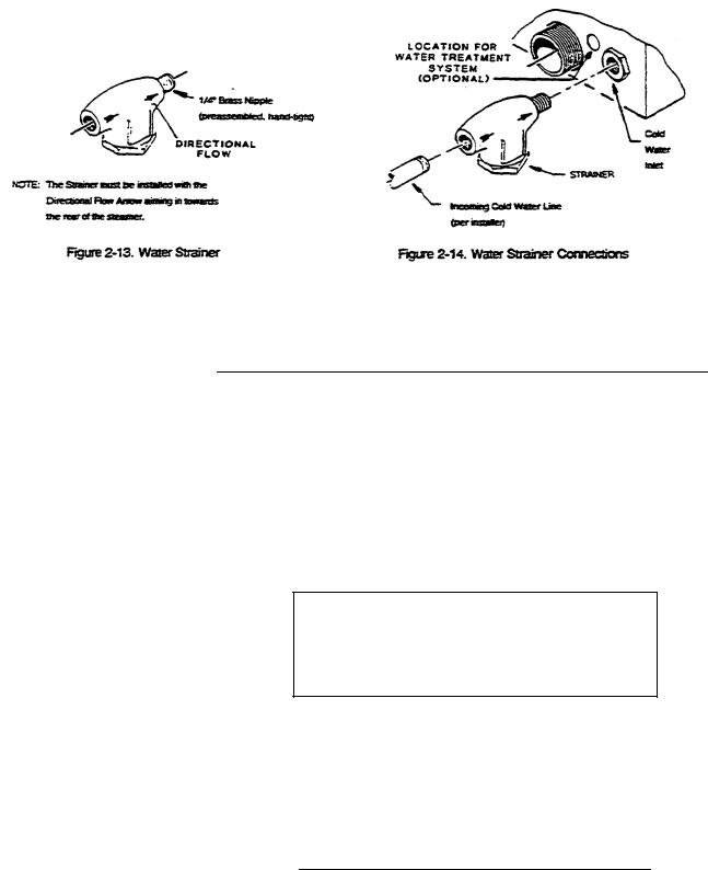
Install The Water Strainer
Figure 2-12. Slide Racks
As illustrated in figure 2-l3, the water strainer is supplied with a 1/4" brass nipple threaded into the strainer outlet This nipple fits the untreated water connection (cold water inlet, figure 2-14).
1.Check that the nipple is connected to the strainer output as indicated
by the flow direction arrow on the strainer body. |
2. Apply pipe |
dope or teflon tape to the brass nipple. |
|
|
Printed 4/90 |
Page 16 CET-16 Service Manual
3.Thread the nipple into the bulkhead coupling of the untreated water connection.
4.Using a pipe wrench, thread the assembled strainer and nipple into the coupling until it is tight, and the strainer access nut is facing down.
Position and Level Steamcraft V For efficient operation, the steamer should be level both front to back and side to side. The adjustable legs of the SteamCraft V are four inches long when the adjustable feet arc fully retracted. The adjustable feet can be extended approximately two inches, providing adjustment for leveling the steamer.
1.Refer to the Installation Check List, Table 2-1 Check that all Preparation Tasks are complete, Check that all Unpacking and Assembly tasks are complete.
2.Looking at the counter where the SteamCraft V will be placed, estimate the location of the four corners that will support the legs. Using a carpenter's level, determine the highest comer and mark it with an "H".
WARNING
INJURY AND EQUIPMENT DAMAGE could result from improper lifting. The SteamCraft V weighs approximately 120 pounds. Use an adequate number of personnel with experience in lifting heavy equipment to place the Steam-Craft V on the counter.
3. Lift the SteamCraft V into place on the counter. Do not change the height of the leg in the highest corner of the counter as marked in step 2. Using a carpenter's level, adjust the other three legs until the unit is level both front to back and side to side.
Printed 4/90
CET-16 Service Manual Page 17
Connect Electrical Line
Referring to Electric Power Line (page 9), verify that the electric power lines have been extended to the SteamCraft V properly. Connect them to the terminal block inside the rear cover as described below.
1.Move the SteamCraft V so the rear panel can be easily reached.
2.Remove the rear panel by removing six screws (figure 2-15) that hold it in place. Save the screws.
3.Mechanically secure the flexible conduit to the electrical conduit access note (figure 2-15). (See Canadian Wiring Considerations
below.)
4. The terminal block and ground connection are near the left side of the rear opening. The unit has either a three terminal block for 3 wire DELTA connection, or a four terminal block for 4 wire WYE connection.
5.Refer to the connection diagrams in figure 2-16, and connect the wires to the terminal block and ground connector accordingly.
6.Each steamer MUST be electrically grounded by the installer.
7.All SteamCraft V's are wired for 3 phase only, and are not convertible to single phase.
8.If no further work is required inside the SteamCraft V, secure the rear panel in place using six mounting screws (figure 2-15).
Figure 2-15. Rear Panel Removal
Printed 4/90
Page 18 CET-16 Service Manual
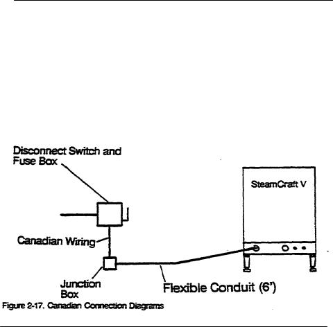
Canadian Wiring Considerations.
For all applications in Canada, install the electrical power lines in accordance with local codes and/or the Canadian Electrical Code, CSA Standard C22-1 (Canada).
•Canadian steamers are supplied with six feet of flexible conduit connected to the steamer and wired to the terminal block at the factory.
•The electrical supply line ends in a Junction box behind the steamer far connection of the SteamCraft V flexible cable.
•Connect the wires from SteamCraft V flexible cable to those in the Junction box according to figure 2-17.
•Each steamer MUST be electrically grounded by the installer.
Connect Untreated Water Line
Referring to Water Supply Lines (page 10) and figure 2-2, verify that the water supply line has been extended to the SteamCraft V properly. Connect the supply line to the SteamCraft V as described below.
1.If the untreated water supply fines are larger than 1/4" L.P.S., verify that a pressure reducer has been installed to maintain the SteamCraft V water pressure requirements specified in Water Supply Lines (page 10).
2. If the water strainer is not already connected to the SteamCraft V, refer to Install The Water Strainer (page 15), and connect the water strainer to the untreated water intake bulkhead coupling.
3.Remove the SteamCraft V rear panel by removing six screws (figure 2- 15) that hold it in place. Save the screws.
4.Verify that the cold water steam generator feed line and cold water condenser feed lines are properly connected for the water supply arrangement being used.
Printed 4/90
CET-16 Service Manual Page 19
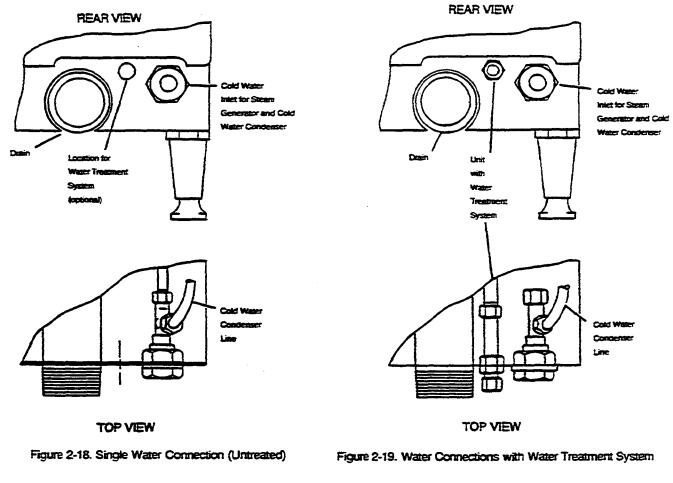
• If the water supply arrangement does not include a water treatment system; refer to figure 2-18, and verify that the cold water steam
generator feed and condenser feed lines are attached to the tee and bulkhead coupling inside the steamer.
•If the water supply arrangement includes a water treatment system; refer to figure 2-19, and verify that the cold water condenser feed line is attached to the tee and bulkhead coupling inside the steamer.
Verify that the steam generator supply outlet of the tee has been securely capped.
5.Flush the water supply line before connecting it to the strainer intake port
6.Apply pipe dope or teflon tape to the threads of the water supply line, and securely connect the supply line to the strainer input port.
7.Turn on the untreated water supply, and check the lines for signs of leakage, both outside and inside the steamer.
8.If no further work is required inside the SteamCraft V, secure the rear panel in place using six mounting screws (figure 2-l5).
Printed 4/90

Page 20 CET-16 Service Manual
Connect Treated Water Line
Referring to Water Supply Lines (page 10) and Figure 2-3, verify that the water supply fine has been extended from the SteamerGard water treatment system to the SteamCraft V properly. Connect the treated water supply line to the SteamCraft V as described below.
1.Refer to the SteamerGard installation manual and verify that it has been installed properly for this application.
2.Verify that a check valve has been installed between the SteamerGard water treatment system and the SteamCraft V.
3.Remove the SteamCraft V rear panel by removing six screws (figure 2- 15) that hold it in place. Save the screws.
4.Referring to figure 2-19, inspect the SteamCraft V to verify that the treated water supply bulkhead coupling has been properly installed and securely attached to the steam generator feed line inside the steamer.
5.Flush the treated water supply Iine before connecting it to the steam generator intake bulkhead coupling.
6.Apply pipe dope or teflon tape to the threads of the treated water supply fine, and securely connect the supply fine to the steam generator intake bulkhead coupling.
7.Turn on the treated water supply, and check the lines for signs of leakage, both outside and inside the steamer
8.If no further work is required inside the SteamCraft V, secure the rear panel in place using six mounting screws (figure 2-l5).
Connect Drain Line |
Referring to Free Air Vented Drain Lines (page 11), verify that the drain |
|
fines meet capacity and venting requirements. Connect the SteamCraft V |
|
dram outlet to the outlet extension and drain fines as described below. |
|
1. The SteamCraft V drain outlet (figure 2-20) is a 1-1/4" NPT pipe |
|
protruding from the back of the unit. An elbow connects this drain |
|
outlet to the drain extension pipe assembled during site preparation. |
|
2. Refer to figure 2-20. The outlet extension fine has a free air vented |
|
connection to floor drain or fines leading to the floor drain |
|
3. When assembling the pipes and fittings of the drain outlet extension, |
|
apply a hardening type pipe sealant to the threads, and thread them |
|
together FINGER TIGHT ONLY. DO NOT USE A WRENCH. |
Printed 4/90
CET-16 Service Manual Page 21
Final Setup And Checkout
This is a simple test procedure to verify that the electrical, water, and drain lines have been property connected to the SteamCraft V. The test also verifies basic operation of the steamer. For a more complete test of the SteamCraft V functions, perform the Function Test on page 23.
Setup
1. Refer to Assembly (page 14) and verify that racks, guard, and cover are properly positioned in the steamer compartment.
2. Refer to figure 2-21, and dose the drain valve (handle points toward right side of the unit).
Printed 4/90
Page 22 CET-16 Service Manual
3.Turn on the main and the untreated water supply valves.
4.If a SteamerGard water treatment system is installed, refer to the SteamerGard manual and start the system. Proceed with setup while the system processes an operating supply of water. If there is a valve
between the SteamerGard and the SteamCraft V, be sure it is open.
5.Refer to electrical schematic, figure 2-6, and verify that the proper size fuses are installed. Turn on electric power to the SteamCraft V at the fused disconnect switch.
6.Close the steamer door.
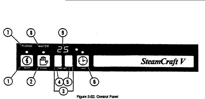
7.Refer to figure 2-22, and turn on the SteamCraft V by pressing the POWER touch pad. The red light above POWER and the WATER alarm light turn on.
•Water begins to fill the steam generator.
•The low water indicator (WATER) remains on until the steam generator is filled with enough water to operate safety.
•When the generator is filled, the WATER light turns off, and the steam generator water begins to heat to stand-by temperature.
TIMED Test -1 Minute
1. If not already done, perform SETUP.
2. Refer to figure 2-22, and set the TIME DISPLAY (9) to 01 minute by pressing the TIME SET minute touch pad (5) once.
3.Start the timed cooking sequence by pressing the TIMED touch pad(6).
•If no TIMED or MANUAL tests have been done, it will Take approximately two minutes for the water in the steam generator to reach operating temperature and begin generating steam.
•The timer counts down to 00 and an alarm beeps four times.
Printed 4/90

CET-16 Service Manual Page 23
MANUAL Test
1. If not already done, perform SETUP.
2. Activate the manual cooking cycle by pressing the MANUAL touch pad
(2).
•The heater elements and the cold water condenser will turn on.
•If no TIMED or MANUAL tests have been done, it will take approximately two minutes for the water in the steam generator to reach operating temperature and begin generating steam
3. Open the steamer door. The compartment should be filled with steam.
•When the door is opened, the heating elements mm off. The steam should dear from the compartment quickly.
4.When the steam has cleared from the compartment, close the steamer door.
•The heater elements and the cold water condenser win turn on, and start generating steam.
5.Open the steamer door. The compartment should again be filled with steam.
6.It necessary, repeat this test to be sure the steam shuts off when the door opens and restarts when the door closes.
TIMED Test - 10 Minutes
1. If not already done, perform SETUP.
2.Refer to figure 2-22, and set the TIME DISPLAY (9) to 10 minutes by pressing the TIME SET 10 minute touch pad (4) once.
3.Start the timed cooking sequence by pressing the TIMED touch pad
(6).
•If no TIMED or MANUAL tests have been done, it will take approximately two minutes for the water in the steam generator to reach operating temperature and begin generating steam.
•The timer counts down to 00 and an alarm beeps four times.
4.When the alarm beeps four times, refer to figure 2-21, and open the drain valve. Measure the temperature of the drain water. It should be
between 150° and 170°.
Printed 4/90
Page 24 CET-16 Service Manual
FUNCTION TEST |
Before S/N WC 9018-90A-05 |
The function Test is a more thorough test of the SteamCraft V than the SetUp and Check-Out procedures. If the checkout has been unsatisfactory or a more thorough inspection is required, perform the following Function Test procedures
Flow, Leak, and Flood Test
1.Do not remove the control panel unless it is necessary to check the lines and fittings inside the SteamCraft V for leaks Remove the control panel as follows.
Printed 4/90
CET-16 Service Manual |
Page 25 |
a. Support the control panel so it doesn't fall when the mounting |
screws |
are removed. |
|
b.DO NOT DISCONNECT any of the control panel wiring.
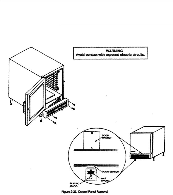
c.Refer to figure 2-23, and remove the mounting screws. Save the screws. Place the panel upright at the base of the steamer.
d.Set a magnet over the door switch as shown in figure 2-23.
CAUTION
DAMAGE TO PANEL ELECTRONICS could result from water splashing or spilling on the circuit board. If water spills or splashes on the circuit board during this test, immediately turn power OFF at the disconnect switch.
2.Open the water supply valve to the steamer and open the steamer drain valve.
3.Turn electricity on at the disconnect switch. Press the POWER touch pad. Check that the red light over the POWER touch pad is on.
4.Water flows through the steamer and drain. Check for water leakage at pipe joints and tube connections or unions. Wait for a few minutes, then look for water leaking from the steam generator. Repair any
leaks before continuing.
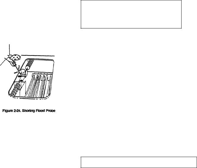
5. As illustrated in figure2-24, use a screwdriver to short the flood probe to ground for four seconds. The FLOOD alarm light flashes. Push the POWER touch pad. The unit will not turn on. The FLOOD alarm light continues to flash.
6.Turn electricity off at the disconnect switch. Wait ten seconds. Turn electricity on at the disconnect switch.
7.Close the steam generator drain valve.
8.Press the POWER touch pad on the Control Panel.
9.The red fight above the touch pad turns on. The alarm WATER displays and TIME displays.
10.After about five seconds, the water solenoid operates, filling the steam generator with water. Check for water leakage around the steam generator.
11.If the control panel was removed to observe the internal pipes and fittings, replace it as follows.
WARNING
Avoid contact with exposed electric circuits.
Printed 4/90
 Loading...