

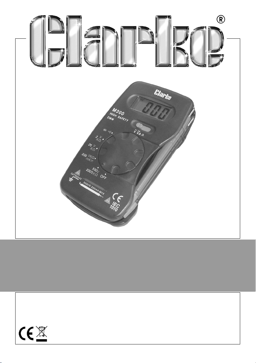
DIGITAL MULTIMETER
MODEL NO: CDM15C
PART NO: 4501145
OPERATING INSTRUCTIONS
GC0415

INTRODUCTION
Thank you for purchasing this CLARKE product.
Before attempting to use this product, please read this manual thoroughly and
follow the instructions carefully. In doing so you will ensure the safety of yourself
and that of others around you, and you can look forward to your purchase
giving you long and satisfactory service.
GUARANTEE
This product is guaranteed against faulty manufacture for a period of 12
months from the date of purchase. Please keep your receipt which will be
required as proof of purchase.
This guarantee is invalid if the product is found to have been abused or
tampered with in any way, or not used for the purpose for which it was
intended.
Faulty goods should be returned to their place of purchase, no product can
be returned to us without prior permission.
This guarantee does not effect your statutory rights.
ENVIRONMENTAL RECYCLING POLICY
Through purchase of this product, the customer is taking on the
obligation to deal with the WEEE in accordance with the WEEE
regulations in relation to the treatment, recycling & recovery and
environmentally sound disposal of the WEEE.
In effect, this means that this product must not be disposed of with general
household waste. It must be disposed of according to the laws governing
Waste Electrical and Electronic Equipment (WEEE) at a recognised disposal
facility.
2
Parts & Service: 020 8988 7400 / E-mail: Parts@clarkeinternational.com or Service@clarkeinternational.com
SAFETY INFORMATION
WARNING: TAKE CARE WHEN USING THIS METER. IMPROPER USE CAN
RESULT IN ELECTRIC SHOCK OR DAMAGE TO THE METER. TAKE ALL
NORMAL SAFETY PRECAUTIONS AND FOLLOW THE SAFEGUARDS
SUGGESTED IN THIS MANUAL.
BEFORE USE
1. When using the meter, the user must observe all normal safety rules
concerning:
• General protection against electric shock
• Protection of the meter against misuse.
2. When the meter is delivered, confirm it has not been damaged in transit.
3. The test leads must be kept in good condition. Before using, check that the
insulation on the test leads has not been damaged or any wire exposed.
4. Use only the test leads supplied to ensure operational safety. If necessary,
they must be replaced with test leads of the same model or class.
DURING USE
1. Do not take measurements that exceed the maximum values for this
meter.
2. Do not touch the metal probes of the test leads when the meter is
connected to the circuit being measured.
3. Do not take voltage measurements if you suspect the value exceeds 600V.
4. If the appropriate value range is unknown, select the highest range on the
scale.
5. Disconnect the test leads from the circuit under test before turning the
rotary function selector.
6. Do not measure the resistance, diode or continuity of live circuits.
7. Do not connect the meter to any voltage source while the rotary selector is
in the Current, Resistance, Diode or Continuity range.
8. Do not use the meter near explosive gases or steam.
9. Stop using the meter if any abnormalities or faults are observed.
10. Do not use the meter unless its rear case and battery cover is correctly and
securely fastened.
3
Parts & Service: 020 8988 7400 / E-mail: Parts@clarkeinternational.com or Service@clarkeinternational.com

11. Do not store or use the meter in areas exposed to direct sunlight, at high
temperature or with high relative humidity.
12. To avoid false readings, replace the batteries as soon as the Low Battery
indicator appears.
13. Before use, verify the meter operation by measuring a known voltage.
14. Never touch exposed wiring, connections or any live circuit while taking
any measurements.
15. Keep your body isolated from ground by using dry clothing, rubber shoes,
rubber mats or any approved insulating material.
SAFETY SYMBOLS
Please read all of the safety and operating instructions carefully before using
this product. The following safety symbols may be found on the product.
General hazard
warning
Class II cabling without
earth conductor.
Earth Falls under WEEE
directive for disposal of
electrical goods
4
Parts & Service: 020 8988 7400 / E-mail: Parts@clarkeinternational.com or Service@clarkeinternational.com

FEATURES
FEATURES OF THE METER
1. LCD Display
2. Range Switch
• Selects different ranges
3. Function Switch
• Select different functions and range
4. Test Leads
• Red test lead for positive/ black test lead for negative
Parts & Service: 020 8988 7400 / E-mail: Parts@clarkeinternational.com or Service@clarkeinternational.com
5
MEASUREMENT FEATURES OF THIS METER
• AC Voltage measurement:-
• DC voltage measurement:-
• DC current measurement:- A
• Resistance measurement:- Ω
• Diode measurement:-
• Continuity:-
ITEMS SUPPLIED
• Multi-meter with pair of test lead/probes (1 red/1 black)
SPECIFICATION
Model Number CDM15C
Product Dimensions: (D x W x H) 21 x 70 x 122 mm
Weight 104 g
Test leads length (inc probes) 470 mm
Max voltage between input & earth CATII 600V
Fuse FF 200mA/600V
Power 12V battery
Maximum display value 1999
Over-range indication “1”
Polarity Display “-” for negative polarity
Detects and measures voltages DCV 2 ± 0.5%, 20/200/ 500 ± 0.8%
ACV 200, 500: ±1.2%
Detects and measures resistance Ohm 2k/20k/200k/2000k ± 1.0%,
Detects and measures current DCA: 200m ± 2%
Operating Temperature
Storage temperature
°C
0-40
-10°C to 50°C
6
Parts & Service: 020 8988 7400 / E-mail: Parts@clarkeinternational.com or Service@clarkeinternational.com

OPERATING VALUES
Before taking the measurement of voltage with the probe, make sure there is
no electronic device connected to the test socket of the instrument.
DC VOLTAGE MEASUREMENT
Range Resolution Accuracy
2V 1mV
20V 10mV
200V 100mV
500V 1V ± 0.8% of reading, ± 1 digit
• Overload protection: 500V DC
DC CURRENT MEASUREMENT
Range Resolution Accuracy
200mA 0.1mA ± 2.0% of reading, ± 2 digits
• Overload protection: 200mA/600V fuse
AC VOLTAGE MEASUREMENT
± 0.5% of reading, ± 1 digits
Range Resolution Accuracy
200V 100mV
500V 1V
• Overload protection: 500V rms AC
• Frequency range: 45 Hz to 450 Hz
• Response: average responding (calibrated in rms of sine wave)
Parts & Service: 020 8988 7400 / E-mail: Parts@clarkeinternational.com or Service@clarkeinternational.com
± 1.2% of reading, ± 10 digits
7

RESISTANCE
Range Resolution Accuracy
2kΩ
20k
Ω
200kΩ
2000kΩ
• Maximum open circuit voltage: 0.65V
• Overload protection: 250V rms AC
DIODE TEST
Range Description
• Overload protection: 250V rms AC
AUDIBLE CONTINUITY TEST
Range Description
1Ω
10Ω
100Ω
1kΩ
Shows the approx. forward voltage drop of the diode
Built-in buzzer sounds when resistance is less than 50
± 1.0% of reading, ±2 digits
± 1.0% of reading, ± 5 digits
Ω
• Overload protection; 250V rms AC
OPERATING INSTRUCTIONS
BEFORE OPERATION
1. Set the function switch to the position.
2. Set the range switch to the desired position. If the magnitude of the
voltage to be measured is unknown beforehand, set the range switch to
the highest position and then reduce until a satisfactory reading is
obtained.
3. Connect the test leads across the source or load being measured. The
polarity of the red lead connection will be indicated at the same time as
the voltage value.
8
Parts & Service: 020 8988 7400 / E-mail: Parts@clarkeinternational.com or Service@clarkeinternational.com

4. When the range switch is set to the 500V position. The “HV” symbol will
appear on the display to remind the user of high voltage measurement
and to pay particular attention.
AC VOLTAGE MEASUREMENT
1. Set the function switch to the position.
2. Set the range switch to the desired position. The measurement reading can
be obtained at the 2V and 20V positions, but the accuracy is not
guaranteed.
3. Connect the test leads across the source of the loads being measured and
read the voltage value on the LCD display.
4. When the range switch is set at the 500V position an HV symbol will appear
on the display to remind the user of high voltage measurement.
DC CURRENT MEASUREMENT
1. Set the function switch to the “A” position.
2. Set the range switch to the 200mA position. (measurement readings can
be obtained at other positions but the decimal point will be in the wrong
place.
3. Open the circuit in which the current is to be measured and connect the
test leads in series with the circuit.
4. Read the current value on the LCD along with the polarity of the red lead
connection.
RESISTANCE MEASUREMENT
1. Set the function switch to the “Ω” position. (note:- the polarity of the red
lead is positive “+”)
2. Set the range switch to the desired position.
3. Connect the test leads across the resistor being measured and read the
LCD display.
4. If the resistor being measured is connected to a circuit, turn off the power
and discharge all capacitors before applying the test leads.
DIODE MEASUREMENT
1. Set the function switch to the “
Ω” position. (note:- the polarity of the red
lead is positive “+”)
2. Set the range switch to the position.
3. Connect the red test lead to the anode of the diode to be tested and the
black lead to the cathode of the diode.
9
Parts & Service: 020 8988 7400 / E-mail: Parts@clarkeinternational.com or Service@clarkeinternational.com

4. The approximate forward voltage drop of the diode will be displayed in mv
if the connection is reversed. Only the figure “1” will be shown.
AUDIBLE CONTINUITY TEST
1. Set the function switch to the “
2. Set the range to the position.
3. Connect the test leads to the two points of the circuit to be tested. If the
resistance is less than 50Ω the buzzer will sound.
Ω” position.
MAINTENANCE
GENERAL CARE
WARNING: BEFORE REMOVING THE REAR COVER, DISCONNECT THE
PROBES FROM THE CIRCUIT TO BE MEASURED. ENSURE THE COVER IS
TIGHTLY SECURED BEFORE USING THE INSTRUMENT.
Clean the housing of the meter only with a damp rag dipped in a little
detergent but never any chemical solution.
In case of any abnormality, stop using the meter and sent it for maintenance.
REPLACEMENT OF BATTERY AND FUSE
1. If the symbol appears on the LCD it indicates that the battery should be
replaced. Undo the screw on the back of the meter to open the case. The
battery for this meter is 12V GP23A and the replacement should be of the
same specification.
2. Replacement of the fuse, if necessary is better done by your Clarke Service
department using the type listed on page 6.
3. Never use the meter until the rear cover is secured after replacing a
battery or fuse.
10
Parts & Service: 020 8988 7400 / E-mail: Parts@clarkeinternational.com or Service@clarkeinternational.com
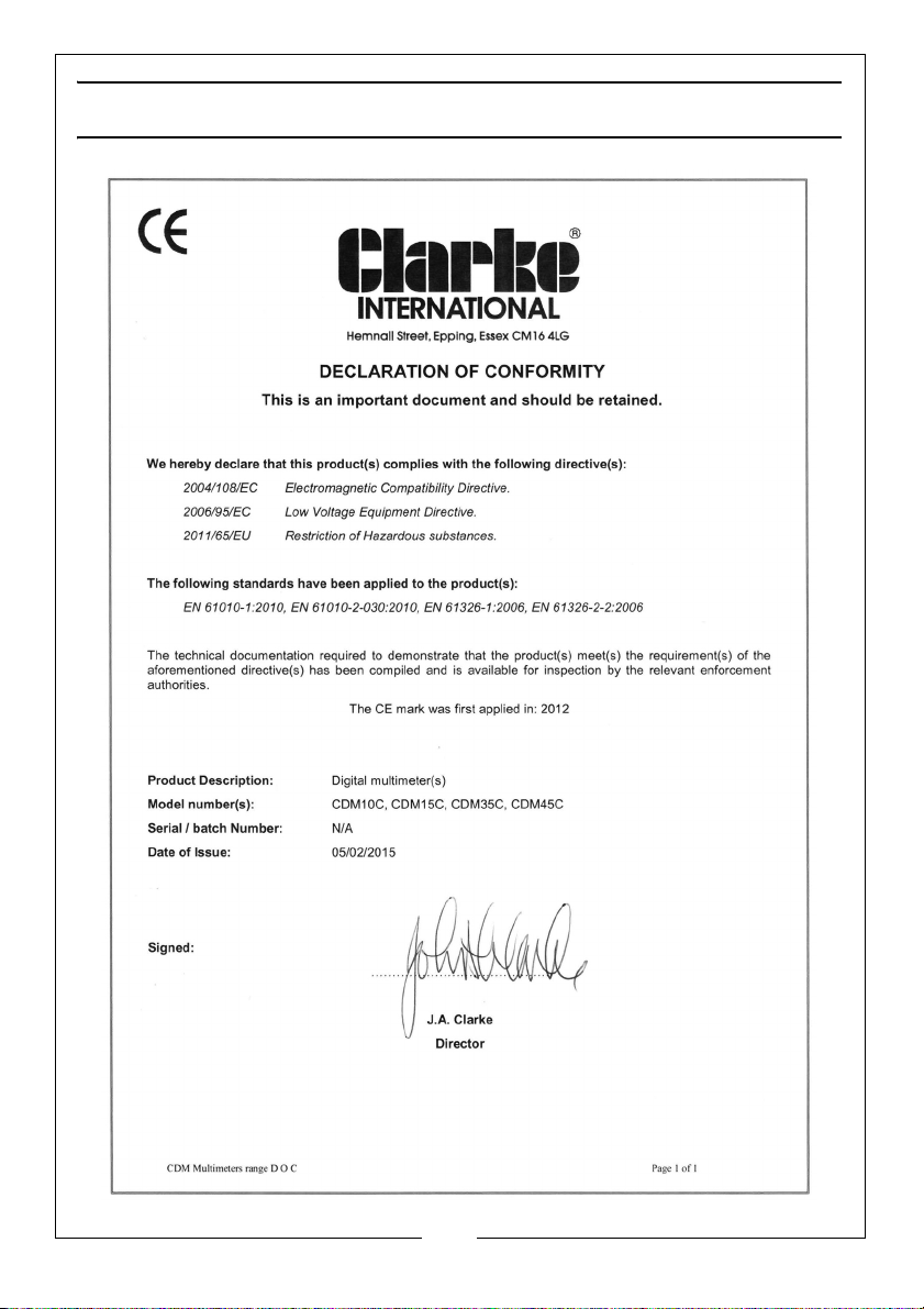
DECLARATION OF CONFORMITY
11
Parts & Service: 020 8988 7400 / E-mail: Parts@clarkeinternational.com or Service@clarkeinternational.com

 Loading...