

Page 1
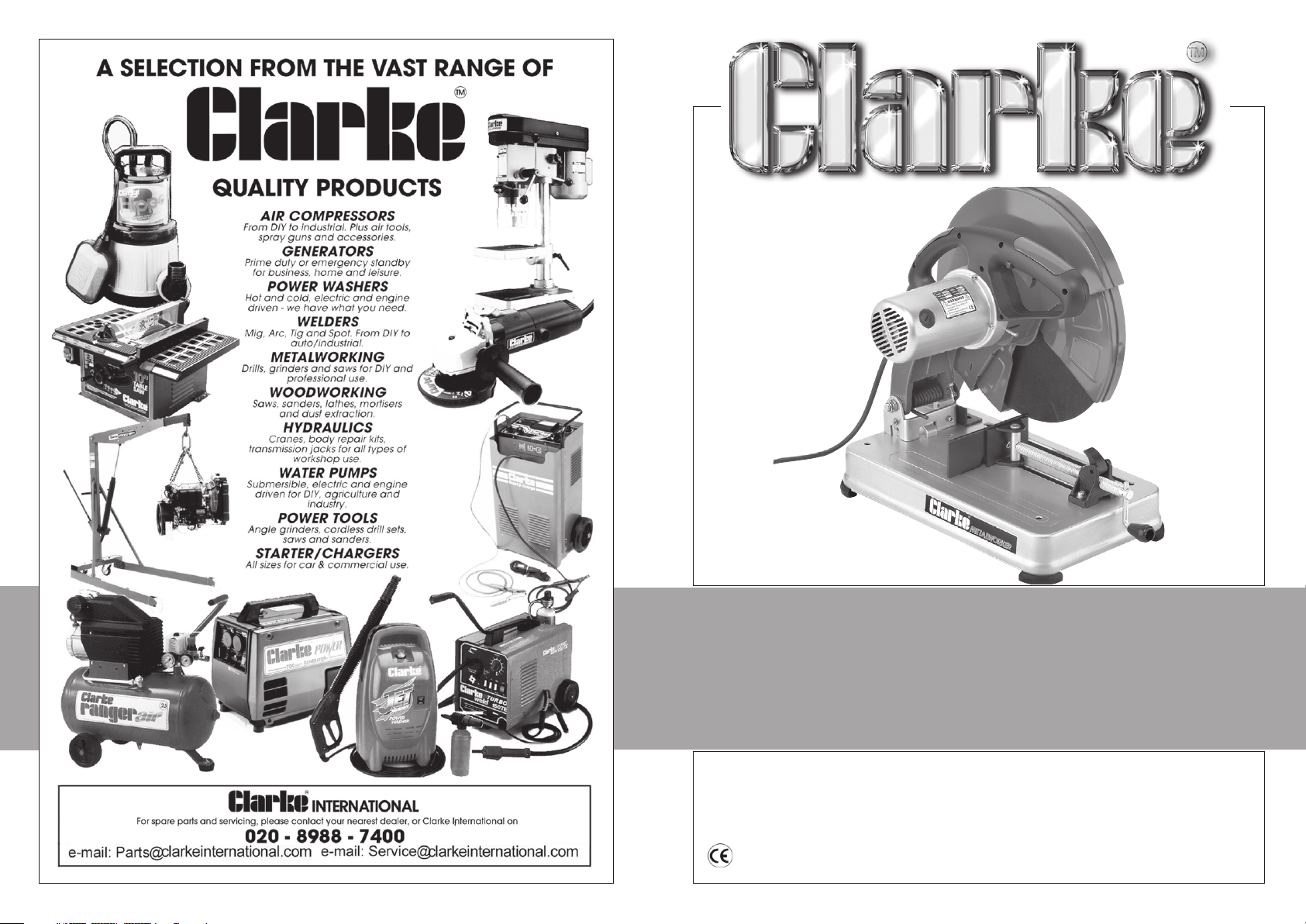
355mm (14")
355mm (14")
ABRASIVE CUT-OFF SAW
ABRASIVE CUT-OFF SAW
Model No. CCO14
Part No. 6470167
OPERATING & MAINTENANCE
INSTRUCTIONS
02/08
Page 2
Thank you for purchasing your CLARKE 14" Abrasive Cut-off Saw.
Before attempting to operate this machine, please read this instruction manual
thoroughly, and follow all directions carefully. By doing so you will ensure the safety
of both yourself and others around you, and at the same time, you should look
forward to the saw giving you long and trouble free service.
GUARANTEE
This product is guaranteed against faults in manufacture for 12 months from date
of purchase. Keep your receipt as proof of purchase.
This guarantee is invalid if the product has been found to have been abused or
tampered with in any way, or not used for the purpose for which it was intended.
The reason for return must be clearly stated.
This guarantee does not affect your statutory rights.
DECLARATION OF CONFORMITY
We declare that this product conforms to the following standards/directives
• 98/37/EC
• 73/23/EEC
• 93/68/EEC
Description: .............. Abrasive Cut-Off Saw
Model No: .............. CCO14
Serial/Batch No: .............. See product Data Plate
signed:
TABLE OF CONTENTS PAGE
General Safety Precautions for Power Tools.................................3
Additional Safety Rules Saws .......................................................... 4
Electrical Connections .................................................................... 5
Unpacking & Assembly ...................................................................6
Features ............................................................................................7
Operation ......................................................................................... 8
Maintenance ...................................................................................8
Specifications ................................................................................... 9
Parts Diagram ..................................................................................10
Parts List ............................................................................................ 11
SPARE PARTS LIST
No. Description Qty Part No.
1 Base Reinforcer 1 TMCCCO1401
2 Plate 1 TMCCCO1402
3 Base 1 TMCCCO1403
4 Fixed Clamp 1 TMCCCO1404
5 Rubber Foot 4 TMCCCO1405
6 Cl;amping Screw 1 TMCCCO1406
9 Quick Clamping Nut1 TMCCCO1409
10 Split Pin 1 TMCCCO1410
12 Action Clamp 1 TMCCCO1412
13 Pin 1 TMCCCO1413
20 Dust Extractor 1 TMCCCO1420
26 Hollow Shaft 1 TMCCCO1426
27 Link Bracket 1 TMCCCO1427
28 Bracket 2 TMCCCO1428
30 Limit Stop 2 TMCCCO1430
32 Torsion Spring 1 TMCCCO1432
36 Pin 1 TMCCCO1436
37 Housing 1 TMCCCO1437
38 Carbon Brush Cap 2 TMCCCO1438
39 Carbon Brush 2 TMCCCO1439
40 Brush Holder 2 TMCCCO1440
42 Stator I TMCCCO1442
43 Fan Guide 1 TMCCCO1443
44 Bearing 2 TMCCCO1444
45 Armature 1 TMCCCO1445
46 Lock Pin 1 TMCCCO1446
47 Spring 1 TMCCCO1447
48 Circlip 1 TMCCCO1448
50 Bearing 1 TMCCCO1450
51 Rubber Buffer I TMCCCO1451
52 Bearing Carrier 1 TMCCCO1452
53 Shaft 1 TMCCCO1453
No. Description Qty Part No.
54 O-Ring 1 TMCCCO1454
55 Large Gear 1 TMCCCO1455
56 Bearing 1 TMCCCO1456
57 Bearing Holder 1 TMCCCO1457
58 Fixed Guard 1 TMCCCO1458
59 Guard Cover 1 TMCCCO1459
60 Location Gasket 1 TMCCCO1460
61 Outer Flange 1 TMCCCO1461
62 Gasket 1 TMCCCO1462
63 Abrasive Disk 1 See CLARKE dealer
64 Wheel Flange 1 TMCCCO1464
65 Flange Washer 1 TMCCCO1465
67 Small Action Guard 1 TMCCCO1467
68 Back Spring 1 TMCCCO1468
70 Small Link 1 TMCCCO1470
72 Nut Special 2 TMCCCO1472
73 Big Link 1 TMCCCO1473
74 Front Spring 1 TMCCCO1474
76 Separation Plate 1 TMCCCO1476
77 Large Action Guard 1 TMCCCO1477
78 Location Plate 1 TMCCCO1478
79 Circlip 1 TMCCCO1479
81 Power Cable 1 TMCCCO1481
82 Handle Left 1 TMCCCO1482
83 Terminal 4 TMCCCO1483
84 Rubber Sleeve 1 TMCCCO1484
86 Cable Clamp 1 TMCCCO1486
88 Handle Right 1 TMCCCO1486
89 Hand Grip Upper 1 TMCCCO1489
90 Hand Grip Lower 1 TMCCCO1490
91 Switch 1 TMCCCO1491
92 Capacitor 1 TMCCCO1492
2
11
Page 3
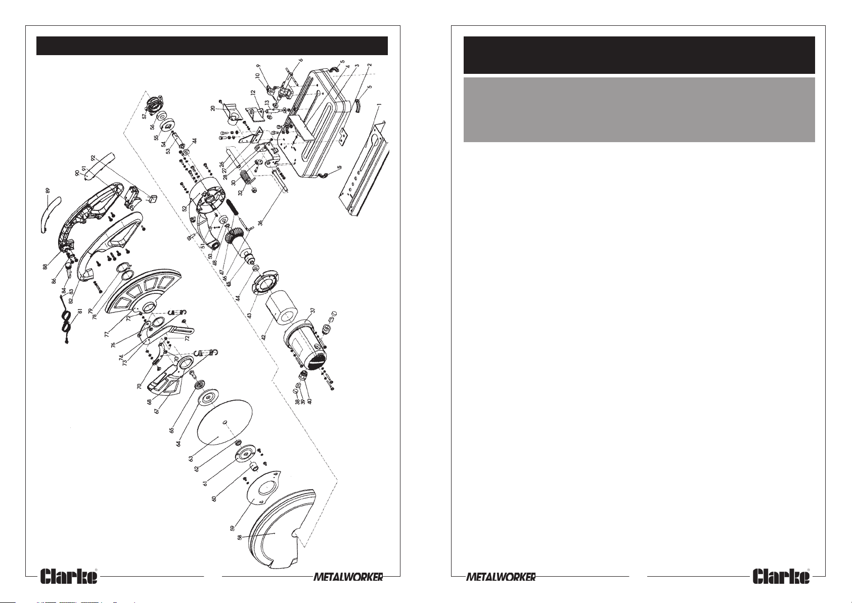
SPARE PARTS DIAGRAM
10
GENERAL SAFETY PRECAUTIONS FOR OPERATING
POWER TOOLS
WARNING
As with all machinery, there are certain hazards involved with their operation
and use. Exercising respect and caution will considerably lessen the risk of
personal injury. However, if normal safety precautions are overlooked, or
ignored, personal injury to the operator, or damage to property may result.
1. KNOW YOUR MACHINE. Read the manual carefully. Learn the machines’
applications and limitations, as well as the specific potential hazards peculiar to it.
2. KEEP GUARDS IN PLACE and in working order.
3. EARTH ALL MACHINES. If the machine is equipped with three-pin plug, it should
be plugged into a three-pin electrical socket. Never remove earth pin.
4. REMOVE ADJUSTING KEYS AND WRENCHES. Form a habit of checking to
ensure that keys, wrenches and tools are removed from the machine.
5. KEEP WORK AREA CLEAN. Cluttered areas and benches invite accidents.
6. DON’T USE IN DANGEROUS ENVIRONMENT. Don’t use machinery in damp or
wet locations, or expose them to rain. Keep work area well lit.
7. KEEP CHILDREN AND VISITORS AWAY. All children and visitors should be kept a
safe distance from work area.
8. MAKE WORKSHOP CHILDPROOF - with padlocks, master switches or by
removing starter keys.
9. DON’T FORCE THE MACHINE. It will do the job better and safer, at the rate for
which it was designed.
10. USE THE RIGHT TOOL. Don’t force a tool or attachment to do a job for which
it was not designed.
11. WEAR PROPER APPAREL. Loose clothing, gloves, neckties, rings, bracelets or
other jewellery may get caught in moving parts. Nonslip footwear is
recommended. Long hair should be contained.
12. USE SAFETY GLASSES. Everyday eyeglasses only have impact resistant lenses,
they are NOT safety glasses.
13. USE EAR DEFENDERS.
14. DON’T OVERREACH. Keep proper footing and balance at all times.
15. MAINTAIN TOOLS IN TOP CONDITION. Keep tools sharp and clean for best and
safest performance. Follow instructions for lubricating and changing accessories.
16. ALWAYS DISCONNECT THE MACHINE before servicing or changing
accessories.
17. AVOID ACCIDENTAL STARTING. Ensure the machine is switched OFF before
plugging in.
18. CHECK FOR DAMAGE. If part of the machine (eg. A cover or guard), is
damaged, it should be carefully inspected to ensure that it can perform its’
3
Page 4
intended function correctly. If in doubt, the part should be renewed. Damage to
moving parts or major components should be Inspected by a qualified technician
before operating the machine. Contact your local dealer for advice.
19. DO NOT STAND ON THE MACHINE. Serious injury could occur if the machine is
tipped over. Do not store materials above or near the machine such that it is
necessary to stand on the machine to get to them.
20. NEVER operate a machine when under the influence of alcohol, drugs or
medication.
21. ALWAYS ENSURE THAT ADEQUATE LIGHTING is available. A minimum intensity
of 300 lux should be provided. Ensure that lighting is placed so that you will not
be working in your own shadow.
ADDITIONAL SAFETY RULES FOR METAL CUT-OFF SAWS
WARNING!
THIS MACHINE MUST NOT BE MODIFIED, OR USED FOR ANY PURPOSE
OTHER THAN THAT FOR WHICH IT IS DESIGNED.
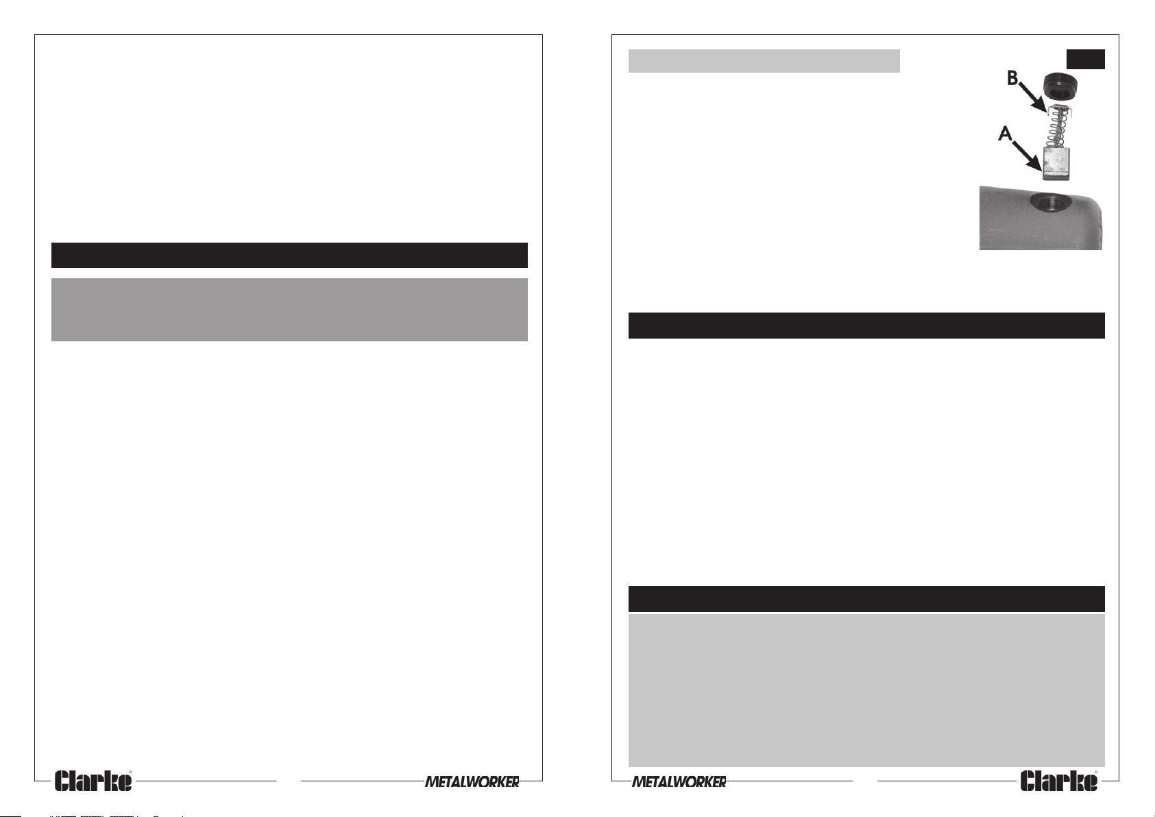
The Motor
Maintenance to the Motor is limited to changing the
carbon brushes.
These will naturally wear with use and require replacing.
They should be checked periodically as follows:
1. Unscrew and remove the plastic covers on the end
of the motor with a screwdriver
2. Pull out the brushes complete with springs and
retainers.
3. Check the brush length, if the ‘wear line’ cannot
be seen (‘A’ fig.8), the pair must be renewed.
4. Replace the brushes, taking care to ensure that the tabs, on the end of the
spring retainer (‘B’ fig.8), correctly enter the elongated chamber as you push
it in and screw on the cap.
Fig.8
SPECIFICATIONS
1. IMPORTANT: You should not operate this machine unless you are thoroughly
familiar with metal cutting saws. If there is any doubt whatsoever, you should
consult a qualified person.
2. Do not operate the machine until it is completely assembled, and this entire
manual, has been read and understood.
3. Ensure the proper electrical regulations are followed.
4. Ensure the abrasive disk is securely mounted in accordance with these
instructions, before connecting to a power supply.
5. DO NOT over tighten the abrasive disk. This can cause stress, and could lead
to the wheel shattering when under load.
6. Always check the abrasive disk for cracks before use.
7. Before switching the machine on, ALWAYS ensure the work is properly
secured, ALWAYS use the vice, NEVER hand hold a workpiece.
8. Make all adjustments with the power OFF.
9. When starting a cut, always ease the tool into the work. A harsh or sudden
impact could shatter the abrasive disk.
10. Ensure the Abrasive Disk reaches maximum speed before beginning a cut.
11. Never use the machine with the guards removed.
12. Ensure you use the correct type of Abrasive Disk for the type of material
being cut. Metal cutting & masonry Abrasive Disks are available from your
Clarke dealer. NEVER cut magnesium, wood, or non-ferrous metals.13.
13. Standard metal section only to be used. This saw is not suitable for cutting
flexible sheet metal sections.
4
Motor Voltage ..................................................... 230V 50Hz 1Phase
Current Rating ..................................................... 10Amps
Power Rating ........................................................ 2,200Watts
Speed ................................................................... 3,750RPM
Disk Diameter .................................................... 14" (355mm)
Thickness ..................................................... 0.125"
Bore ............................................................. 1"
Weight ........................................................ 18kg
Dimensions (overall) ............................................ 535x310x440mm
Please note that the details and specifications contained herein, are correct at the time of going to
print. However, CLARKE International reserve the right to change specifications at any time without
prior notice. Always consult the machine’s data plate
PARTS & SERVICE CONTACTS
For Spare Parts and Service, please contact your nearest dealer,
or CLARKE International, on one of the following numbers.
PARTS & SERVICE TEL: 020 8988 7400
PARTS & SERVICE FAX: 020 8558 3622
or e-mail as follows:
PARTS: [email protected]
SERVICE: [email protected]
9
Page 5
OPERATION (Ref. Fig. 1)
ELECTRICAL CONNECTIONS
Ensuring the workpiece is properly clamped, and observing all precautions
previously mentioned, switch ON by pressing the safety lock button before pulling
the ON/OFF trigger switch upwards. Allow the wheel to reach full speed then
gently lower it on to the work. DO NOT try to cut too harshly.
The switch is a ‘dead man’ type and the motor will stop therefore, when it is
released.
NOTE:
Take great care when cutting with a new wheel. DO NOT press too heavily
particularly at the end of a cut.
MAINTENANCE
Before use, always check the condition of the Abrasive Disk to ensure there are no
cracks or badly pitted edges. If in doubt, you must renew the wheel.
Always keep the machine clean and dry. Brush away dust and metal chippings.
Changing the Abrasive Disk
IMPORTANT!
Ensure the replacement disk is rated above
the rated speed of ther machine.
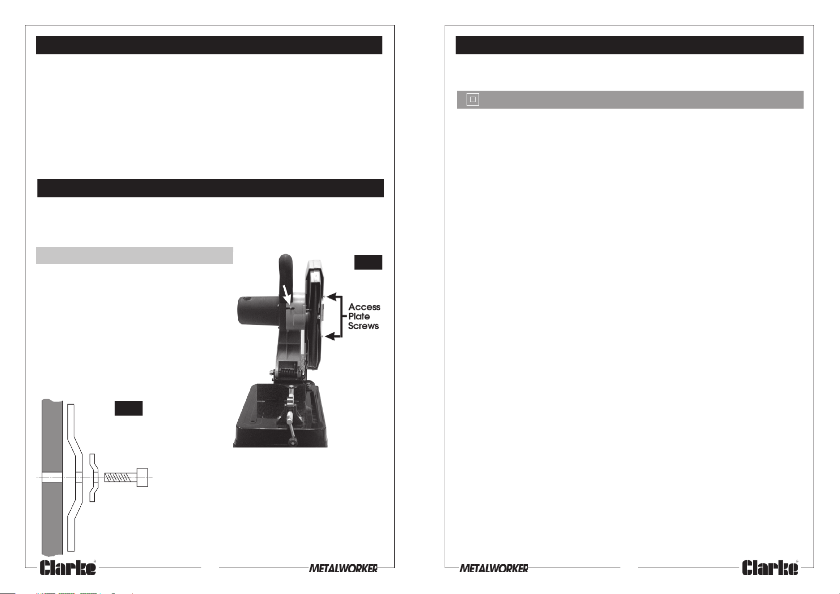
Having disconnected the power supply,
Raise the Upper Blade Guard, by hand, as
high as possible, then slide the bar, arrowed
in fig.6, across, so that it retains the Blade
Guard in place, as shown.
Slacken off the two screws which secure
the Abrasive Disk Centre Bolt access plate,
shown in fig 6, and remove the plate.
Fig.7
Fig.6
Connect the mains lead to a standard, 230 Volt (50Hz) electrical supply through an
approved 13 amp BS 1363 plug, or a suitably fused isolator switch.
WARNING! THIS APPLIANCE IS DOUBLE INSULATED
IMPORTANT: The wires in the mains lead are coloured in accordance with the
following code:
Blue - Neutral
Brown - Live
As the colours of the flexible lead of this appliance may not correspond with the
coloured markings identifying terminals in your plug proceed as follows:
• Connect BROWN cord to plug terminal marked with letter “L” or coloured RED.
• Connect BLUE cord to plug terminal marked with a letter “N” or coloured
BLACK.
If this appliance is fitted with a plug which is moulded onto the electric cable (i.e.
non-rewirable) please note:
1. The plug must be thrown away if it is cut from the electric cable. There is a
danger of electric shock if it is subsequently inserted into a socket outlet.
2. Never use the plug without the fuse cover fitted.
3. Should you wish to replace a detachable fuse carrier, ensure that the correct
replacement is used (as indicated by marking or colour code).
4. Replacement fuse covers can be obtained from your local dealer or most
electrical stockists.
5. The fuse in the plug must be replaced with one of the same rating (13 amps)
and this replacement must be ASTA approved to BS1362.
Using the 8mm Hex. wrench, undo and remove the
Abrasive Disk Centre Bolt, then remove the washer,
and flange. Finally, carefully remove the Abrasive
Disk.
Reassemble in reverse order, ensuring the Disk, and
flange are correctly mounted on the flats on the
shaft with the flange and washer oriented as shown
in fig.7, Take great care not to over tighten the
centre bolt.
8
If an extension cable is necessary, you MUST comply with the following standard for
230V 10Amp equipment:
Extension Length Cable Section
Up to 20 m ............................... 1.5mm
20m to 50m .............................. 2.5mm
5
2
2
Page 6
UNPACKING and ASSEMBLY
FEATURES
Unpack the saw carefully, and ensure that all items are accounted for, according
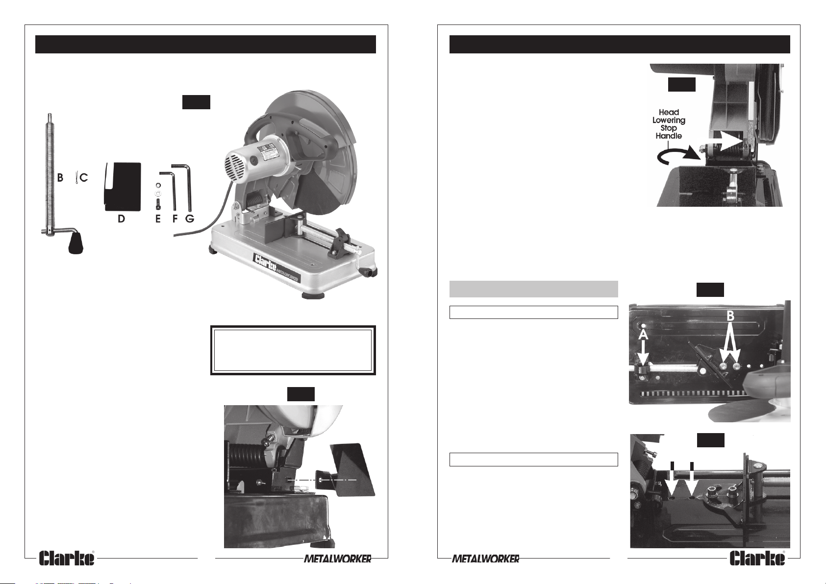
to the following list.
Fig.1
Loose Parts
A
A. Main body
B. Vice Adjuster
C. Split Pin
D. Spark Deflector
E. M5 Hex. Socket head screw
with flat & spring washer
F. Hex wrench 5mm
G. Hex. Wrench 8mm
Fit the Spark Deflector as shown in fig.2,
securing with the M5 Hex. head screw
with flat and spring washer.
Should there be any deficiencies,
you should contact your Clarke
dealer immediately.
Fig.2
6 7
1. A stop is provided to restrict the height to
which the arm may be lowered. The stop is
in the form of a bolt, arrowed in fig. 3 which
should not require adjusting.
2. The vice is provided with a quick adjust
device (shown at A, fig.4). The block,
through which the screw passes, pivots,
and may be lifted off the screw thread.
This releases the screw, and hence the
vice jaw which may then be quickly
moved into contact with the work. The
block is then flipped back into position,
and the work clamped in the normal way
by using the handle.
3. A latch, to prevent the head from being lowered, is provided. Turn the plastic
handle at the rear of the unit, indicated in fig.3, to engage the latch
Before carrying out any adjustments or maintenance, ensure the saw is
disconnected from the power supply.
Adjusting The Vice
Fig.3
Fig.4
a. Bevel Cutting
The vice may be moved up to 45° for
bevel cutting.
To set the required angle, slacken off the
two bolts securing the fixed vice jaw
(Shown at B), and swivel the jaw to the
appropriate angle according to the
scale provided. Use a set square or
angle gauge set against the Abrasive
Disk, if absolute accuracy is required.
Tighten the two securing bolts when
satisfied.
Fig.5
b. Positioning the Fixed Vice Jaw
The fixed jaw may be fixed in one of three
positions to accommodate larger
workpieces.
Undo and remove the two screws
securing the jaw, and reposition as
desired, using the bolt holes arrowed in
Fig.5 to secure the jaw.
 Loading...