

Page 1
VRX610
Owner’s manual & Installation manual
Mode d’emploi et manuel d’installation
Manual de instrucciones y de instalación
VRX610
6.5” MONITOR & FM/AM RADIO WITH
CD/MD CHANGER CONTROL
•
MONITEUR DE 6,5 POUCES ET RADIO FM/AM
AVEC COMMANDE DE CHANGEUR
DE CD/MD
•
MONITOR DE 6,5-PULGADAS Y RADIO FM/AM
CON MANDO PARA EL CAMBIADOR DE
CD/MD
2001/2 (IT·K)
Clarion Co., Ltd.
All Rights Reserved. Copyright © 2001: Clarion Co., Ltd.
Printed in China / Imprimé en Chine / Impreso en Chine /
QC-6700B
280-7653-00
Page 2

Thank you for purchasing the Clarion VRX610.
∗This owner’s manual is for the VRX610.
∗Please read this owner’s manual in its entirety before operating this equipment.
∗After reading this manual, be sure to keep it in a handy place (e.g., glove compartment).
∗Check the contents of the enclosed warranty card and keep it carefully with this manual.
∗This manual includes the operating procedures of the CD changer, MD changer, TV tuner and
digital sound processor (DSP) connected via the CeNET cable. The CD changer, MD changer, TV
tuner and DSP have their own manuals, but no explanations for operating them are described.
Contents
1. PRECAUTIONS...................................... 4
WARNING..............................................4
INFORMA TION FOR USERS.....................4
2. CONTROLS ............................................5
3. NOMENCLATURE ....................................6
Names of Buttons......................................6
JOYSTICK Operation..................................7
4. MODE DISPLA Y........................................8
Display common to each mode....................8
TITLE LIST mode display .............................8
RADIO mode display ...................................9
CD/MD Changer mode display ..................10
TV mode display ........................................11
5. REMOTE CONTROL..............................12
Inserting the Batteries.............................12
Functions of Remote Control Unit Buttons
6. DCP .........................................................14
Removing the DCP.....................................14
Attaching
7. CAUTIONS ON HANDLING......................15
LCD panel/Generalities..............................15
Cleaning..................................................15
8. OPERATIONS .......................................16
Basic Operations....................................16
Radio Operations....................................20
the DCP.....................................14
Turning on and off the power.................16
Selecting a mode.....................................16
Adjusting the volume..............................16
Switching the display ..............................16
Showing a mode display ..........................17
Opening and turning the display ...............17
T urning on and off the monitor..................17
Mute...........................................17
Setting the Z-enhancer............................17
Adjusting the Z-enhancer.........................18
Adjusting the bass and treble...................18
Adjusting the balance and fader...............18
T urning on/off the loudness....................19
FM reception...............................20
Changing the reception area...............20
Listening to the radio...............................20
....13
Tuning.........................................20
Seek tuning...........................................20
Manual tuning.........................................20
Recalling a preset station......................20
Manual memory......................................21
Auto store.................................................21
Preset scan..............................................21
Instant station recall (ISR)......................21
CD Changer Operations...........................22
CD changer functions...............................22
Pausing play.........................................22
Displaying CD titles................................22
Selecting a CD.......................................22
Selecting a track....................................22
Fast-forward/Fast-backward..................23
T op function............................................23
Scan play ................................................23
Disc scan play ..........................................23
Repeat play .............................................23
Disc repeat play ........................................23
Random play ............................................23
Disc random play ......................................23
MD Changer Operations ..........................24
MD changer functions..............................24
Pausing play.............................................24
Switching disc titles and track titles..........24
Scrolling titles.........................................24
Selecting an MD.......................................24
Selecting a track......................................24
Fast-forward/fast-backward...................24
T op function.............................................24
Scan play ................................................25
Disc scan play ..........................................25
Repeat play ..............................................25
Disc repeat play .......................................25
Random play ............................................25
Disc random play ......................................25
2 VRX610 VRX6671z xx
VRX610 163
Page 3
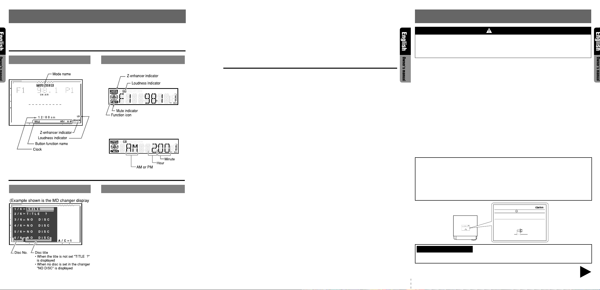
4. MODE DISPLAY
1. PRECAUTIONS
The Color LCD Display and the Information Panel on the main unit show the following displays, providing information about the mode and functions operated.
Display common to each mode
COLOR LCD DISPLAY INFORMATION PANEL
MAIN
Clock Time display
TITLE LIST mode display
COLOR LCD DISPLAY INFORMATION PANEL
TV Operations.......................................26
TV functions.................................26
Watching TV ..........................................26
Watching a video ...................................26
Tuning..........................................26
Seek tuning...........................................26
Manual tuning.......................................26
Recalling a preset station.......................26
Manual memory .....................................27
Auto store.............................................27
Preset scan ..........................................27
Switching the VTR system between
NTSC and P AL
Setting the TV diver ...............................27
Adjusting the brightness and tone of
color..................................................28
Changing over TV display size.............28
Rear Vision Camera ..............................29
Monitoring the rear vision camera.........29
Operation of External Visual
Devices (VISUAL Mode)
Switching to Composite Screen.........29
Other Functions.....................................30
Always turning on the button illumination
on the operation panel..........................30
Entering titles......................................30
Title list play ...........................................30
Clock Adjustment...................................31
Triggerd audio mute for cellular
telepones...................................31
DSP operations.......................................32
DSP control function...........................32
................................27
.............29
Contents
DSP functions.....................................32
Operations common to each mode ...32
Output adjustment of auto loudness,
subwoofer and playback band.........32
Selecting the standard mode or the
professional mode...........................33
Woofer lev el adjustment.......................33
Standard mode/Setting the listening position
Selection of listening position...............33
Detail Adjustment of listening position
Standard mode/G.EQ operations
G.EQ effect ON/OFF............................34
Calling G.EQ BASIC Pattern/USER
Pattern............................................34
Setting and storing G.EQ Properties/
Memory into USER Pattern..............34
Standard mode/DSF operations
DSF effect ON/OFF..............................35
Calling DSF BASIC Pattern/USER
Pattern..............................................35
Setting and storing DSF Properties/
Memory into USER Pattern..............35
Professional mode/VSE operations....36
VSE effect ON/OFF..............................36
Calling VSE BASIC Pattern/USER
Pattern.........................................36
Setting and storing VSE Properties/
Memory into USER Pattern.............36
Professional mode/P .EQ operations....37
P.EQ effect ON/OFF.............................37
Calling P.EQ BASIC Pattern/USER
Pattern.......................................37
Setting and storing P.EQ Properties/
Memory into USER Pattern
...............34
................35
9. IN CASE OF DIFFICULTY........................39
10. ERROR DISPLA YS.................................41
11. SPECIFICATIONS.................................42
Installation and
Wire conneceion manual...........43
...........
33
...
33
.....37
!!
!
!!
WARNING
For your safety, the driver should not watch the TV or operate the controls while driving.
Please note that watching and operating the TV while driving are prohibited by law in some
countries. Also, while driving, keep the volume to a level at which external sounds can be
heard.
1. When the inside of the car is very cold and
the player is used soon after switching on the
heater, moisture may for m on the disc (CD/
MD) or the optical parts of the player and
proper playback may not be possible. If moisture forms on the disc (CD/MD), wipe it off
with a soft cloth. If moisture forms on the optical parts of the player, do not use the pla yer
for about one hour. The condensation will disappear naturally allowing normal operation.
4. TV broadcast reception
When receiving the TV broadcasts, the
strength of the signals changes since the car
is moving, so in some cases it may not be
possible to receive clear pictures.
• TV signals are strongly linear, so reception
is affected by buildings , mountains and other
obstacles.
• Such external factors such as electric train
lines, a high voltage lines, and signal devices
may disturb the picture or cause noise.
2. Driving on extremely bumpy roads which
cause severe vibration may cause the sound
∗ If the reception is poor, switch to a station with
good reception.
to skip.
3. This unit uses a precision mechanism. Even
in the event that trouble arises, never open
the case, disassemble the unit, or lubricate
the rotating parts.
This equipment has been tested and found to comply with the limits for a Class B digital device,
pursuant to Part 15 of the FCC Rules. These limits are designed to provide reasonable protection against harmful interference in a residential installation. This equipment generates, uses,
and can radiate radio frequency energy and, if not installed and used in accordance with the
instructions, may cause harmful interference to radio communications. However, there is no
guarantee that interference will not occur in a particular installation. If this equipment does
cause harmful interference to radio or television reception, which can be determined by turning
the equipment off and on, the user is encouraged to consult the dealer or an experienced radio/
TV technician for help.
MODEL
VRX610
12V GROUND
AM 530kHz-1710kHz
FM 87.9MHz-107.9MHz
THIS DEVICE COMPLIES WITH PART 15 OF THE FCC RULES.
OPERATION IS SUBJECT TO THE FOLLOWING TWO CONDITIONS:
MODEL
AM 530kHz-1710kHz
FM 87.9MHz-107.9MHz
THIS DEVICE COMPLIES WITH PART 15 OF THE FCC RULES.
OPERATION IS SUBJECT TO THE FOLLOWING TWO CONDITIONS:
(1) THIS DEVICE MAY NOT CAUSE HARMFUL INTERFERENCE, AND
(2) THIS DEVICE MUST ACCEPT ANY INTERFERENCE RECEIVED,
INCLUDING INTERFERENCE THAT MAY CAUSE UNDESIRED
SERIAL No.
QC-6700Y
VRX610
12V GROUND
ISO
8mmMAX
286-9601-00
Clarion Co.,Ltd.
MADE IN CHINA
(1) THIS DEVICE MAY NOT CAUSE HARMFUL INTERFERENCE, AND
(2) THIS DEVICE MUST ACCEPT ANY INTERFERENCE RECEIVED,
INCLUDING INTERFERENCE THAT MAY CAUSE UNDESIRED
OPERATION.
SERIAL No.
QC-6700B
ISO
8mmMAX
286-9601-00
Clarion Co.,Ltd.
MADE IN CHINA
8 VRX610
INFORMATION FOR USERS:
CHANGES OR MODIFICATIONS TO THIS PRODUCT NOT APPROVED BY THE MANUFACTURER WILL VOID THE WARRANTY AND WILL VIOLATE FCC APPROVAL.
Be sure to unfold and read the next page. / Veuillez déplier et vous référer à la page suivante.
/ Cerciórese de desplegar y de leer la página siguiente.
VRX610 4VRX610 3
Page 4
CONTROLS / COMMANDES / CONTROLES
2. CONTROLS / COMMANDES / CONTROLES
Main unit / Unité principale / Unidad principal
With the Display closed / Avec l`afficheur fermé / Con el visualisador cerrado
With the Display open / Avec l`afficheur ouvert / Con el visualisador abierto
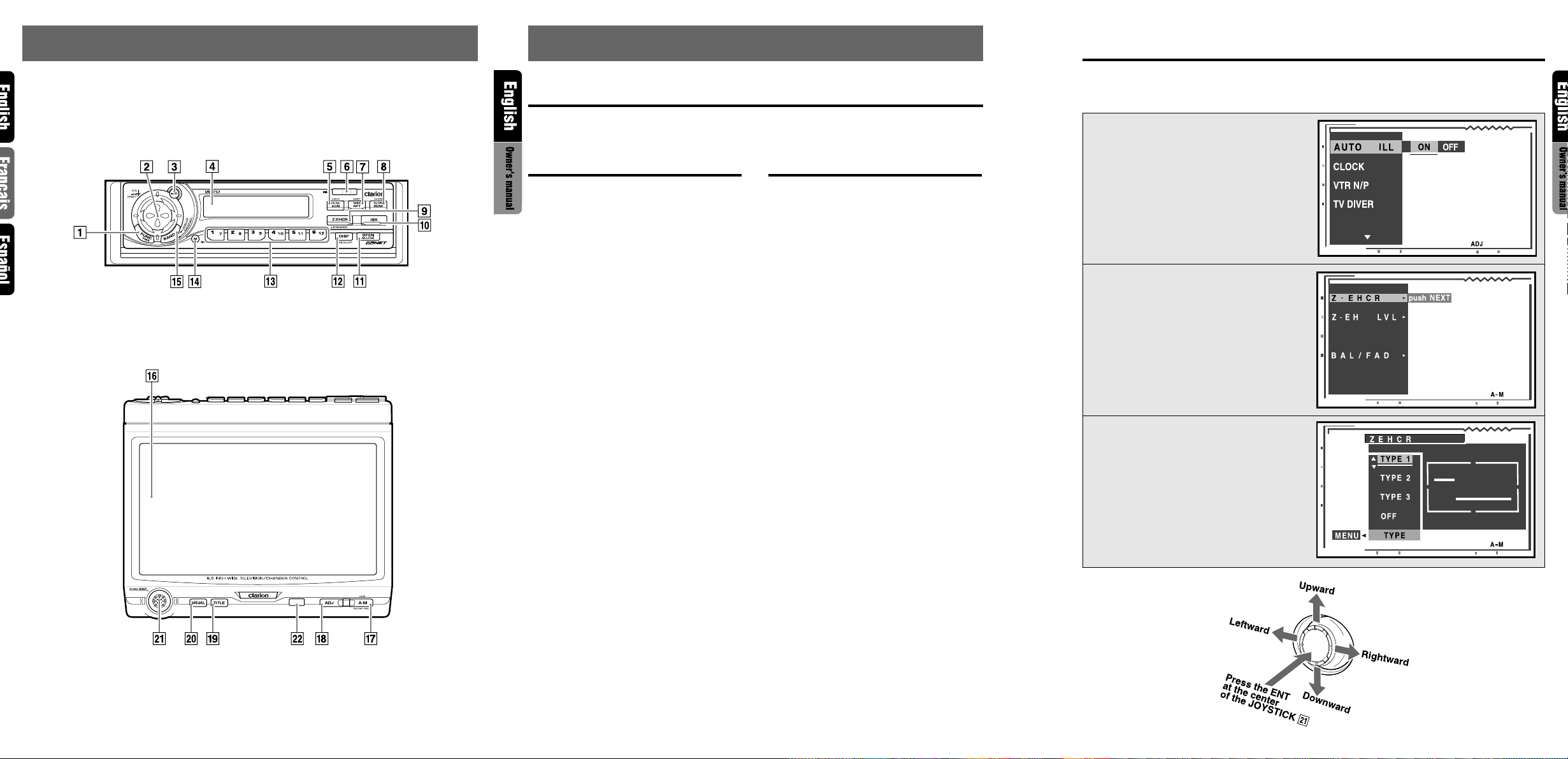
3. NOMENCLATURE
Names of Buttons
Note:
• Be sure to read this chapter referring to the front diagrams of chapter “2. CONTROLS” on page 5 (unfold).
With the display closed With the display open
1 POWER button
FUNC (Function) button
2 SEARCH button
VOLUME button
3 PLAY/PAUSE button
4 Information Panel
5 PS (Preset scan)/AS (Auto store) button
SCN (Scan) button
6 DCP RELEASE lever
7 WIDE button
RPT (Repeat) button
8 TV/VTR button
RDM (Random) button
9 Z-EHCR (Z-enhancer) button
0 ISR button
! OPEN button
M. LOCK(Monitor lock) button
@ DISP (Display) button
MONI ON/OFF button
# PRESET buttons (1 to 6)
DIRECT buttons (1 to 6)
$ MUTE button
% BAND button
¥ Color LCD display
& A-M (Audio-Mode) button
* ADJ (Adjust) button
( TITLE button
) VISUAL button
¡ JOYSTICK
™ Remote Control Infrared Sensor
JOYSTICK Operation
Note:
• Many settings/procedures have to be performed by using the JOYSTICK ¡. Be sure to read this chapter
in order to operate it properly.
● Selecting an item in the menu
Select an item displayed in the menu by operating the JOYSTICK ¡ upward or downward.
● Setting an option for the selected item
When the setting options for an item are listed
on the right of the display, you can choose the
desired option by operating the JOYSTICK ¡
leftward or rightward. Then, press the center of
the JOYSTICK ¡ to set your choice.
● When “push NEXT” is displayed next to
the menu item
1. Press the ENT at the center of the JOYSTICK ¡ to select the item and show the
setting display for this item.
2. Operate the JOYSTICK ¡ upward or downward to select the desired setting option,
then press ENT at the center of the JOYSTICK ¡ to set your choice.
● Returning to the previous mode
Select the item “MENU” by operating the JOYSTICK ¡ leftward or rightward, then press the
ENT at the center of the JOYSTICK ¡.
Note: Be sure to unfold this page and refer to the front diagrams as you read each chapter.
Remarque: Veuillez déplier cette page et vous référer aux schémas quand vous lisez chaque chapitre.
Nota: Cuando lea los capítulos, despliegue esta página y consulte los diagramas.
5 VRX610 6 VRX610 VRX610 7
Page 5
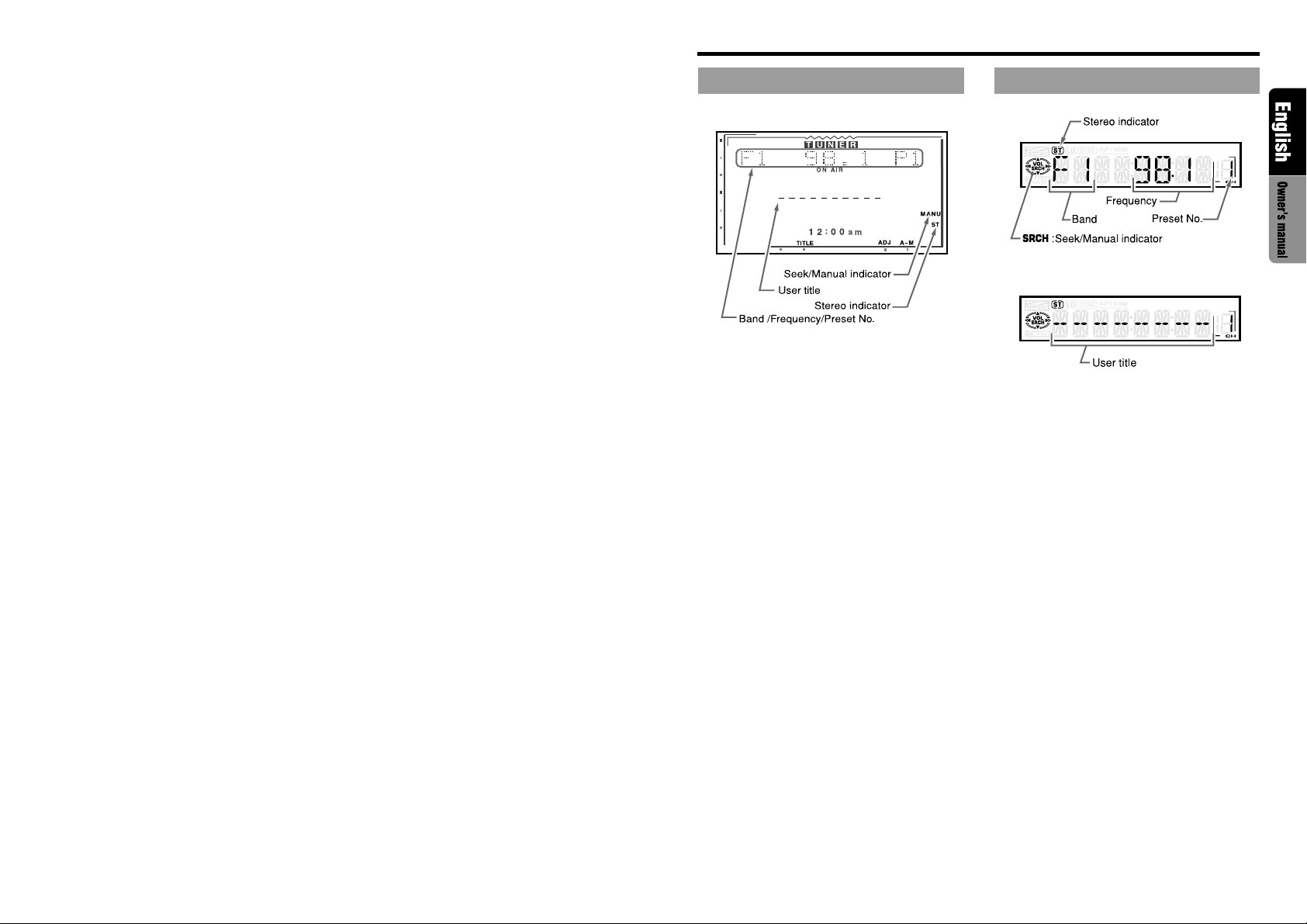
RADIO mode display
COLOR LCD DISPLAY INFORMA TION PANEL
MAIN
SUB
VRX610 9
Page 6
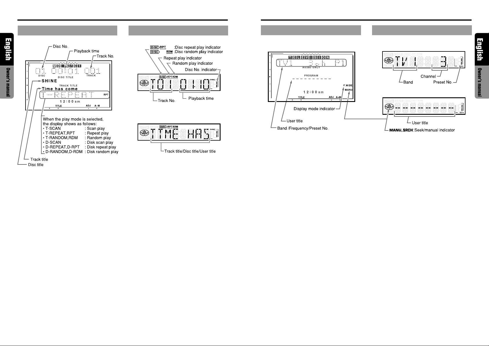
CD/MD Changer mode display
TV mode display
COLOR LCD DISPLAY INFORMA TION PANEL
MAIN
SUB
COLOR LCD DISPLAY INFORMATION PANEL
MAIN
SUB
VRX610 1110 VRX610
Page 7
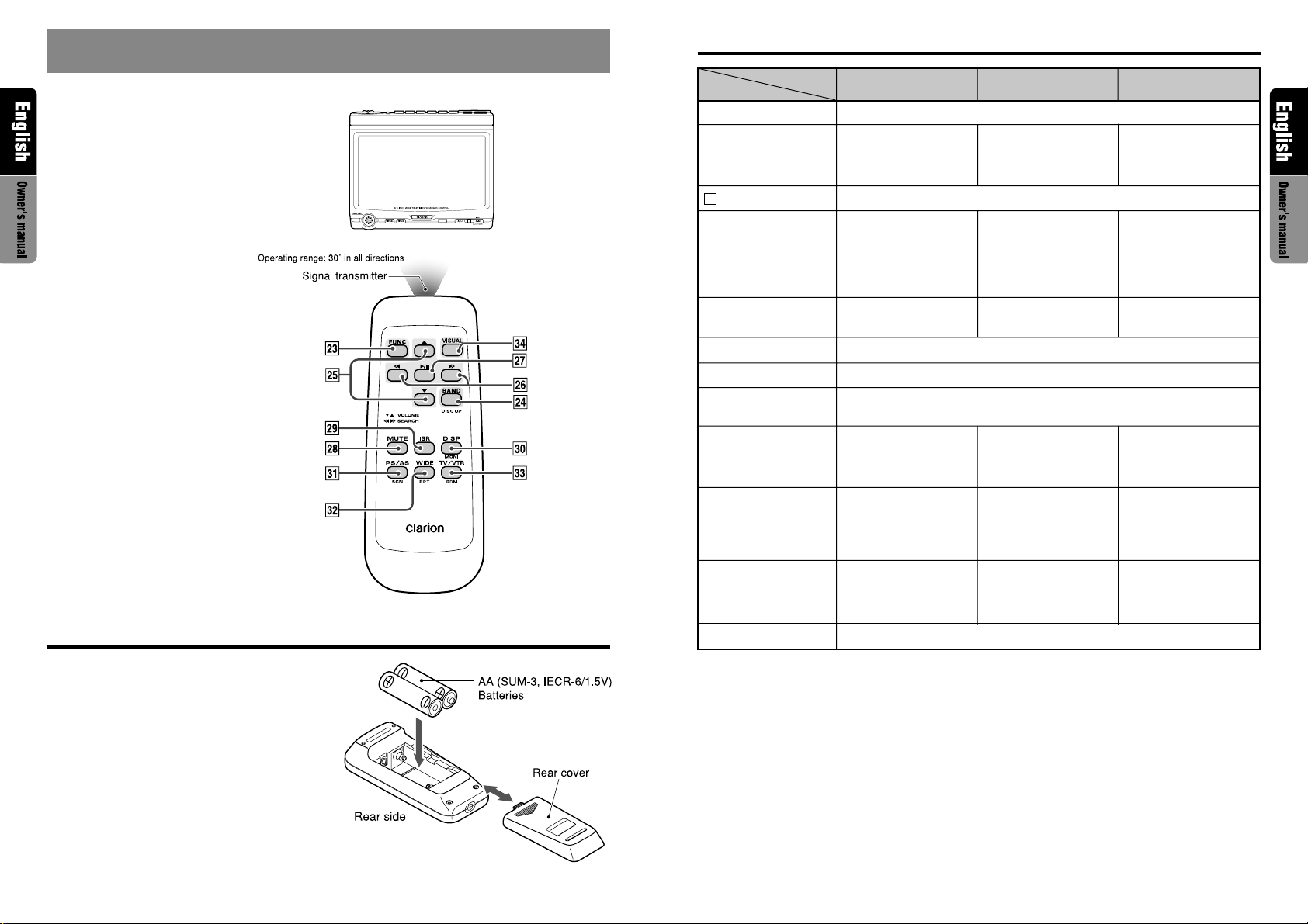
5. REMOTE CONTROL
When the panel is open
Functions of Remote Control Unit Buttons
Button
£ FUNC
¢ BAND
DISC UP
TOP
Mode
Radio
Switches among Radio, CD changer, MD changer and TV.
Switches reception band.
CD changer
MD changer
Moves to the next disc in
increasing order.
Switches reception band.
TV
Remote control unit
Inserting the Batteries
WIDE
1
25
§ SEARCH
¶ PLAY/PAUSE
• MUTE
ª ISR
º
⁄ PS/AS
¤
‹
›
VOLUME
DISP
MONI
SCN
WIDE
RPT
TV/VTR
RDM
VISUAL
Increases and decreases volume (in all modes).
Moves preset channels
up and down.
No function.
Turns mute on and off.
ISR on and off.
Turns on and off the monitor.
Preset scan.
When pressed and
held for 2 seconds:
Auto store.
No function.
No function.
Switches the VISUAL mode.
Moves tracks up and
down.
When pressed and held
for 1 second:
Fast-forward/
Fast-backward.
Switches between
playback and pause.
Scan play.
When pressed and held
for 1 second: Disc scan
play.
Repeat play.
When pressed and held
for 1 second: Disc repeat
play.
Random play.
When pressed and held
for 1 second: Disc
random play .
Moves preset channels
up and down.
No function.
Preset scan.
When pressed and held
for 2 seconds: Auto store.
Switches TV display size.
Switches the VISUAL mode.
Switches between TV and
VTR.
1. Turn the remote control unit over, then slide
the rear cover in the direction of the arrow.
2. Insert the AA (SUM-3, IECR-6/1.5V) batteries that came with the remote control unit
facing in the directions shown in the figure,
then close the rear cover.
Notes:
Using batteries improperly can cause them to explode.
Take note of the following points:
• When replacing batteries, replace both batteries
with new ones.
• Do not short-circuit, disassemble or heat batteries.
• Do not dispose of batteries into fire or flames.
• Dispose of spent batteries properly.
Notes:
• The remote control unit does not work when the panel is closed.
• Some of the corresponding buttons on the main unit and remote control unit have different functions.
VRX610 1312 VRX610
Page 8
6. DCP
7. CAUTIONS ON HANDLING
The control panel can be detached to prevent
theft. When detaching the control panel, store it
in the DCP (DETACHABLE CONTROL PANEL)
case to prevent scratches.
We recommend taking the DCP with you when
leaving the car.
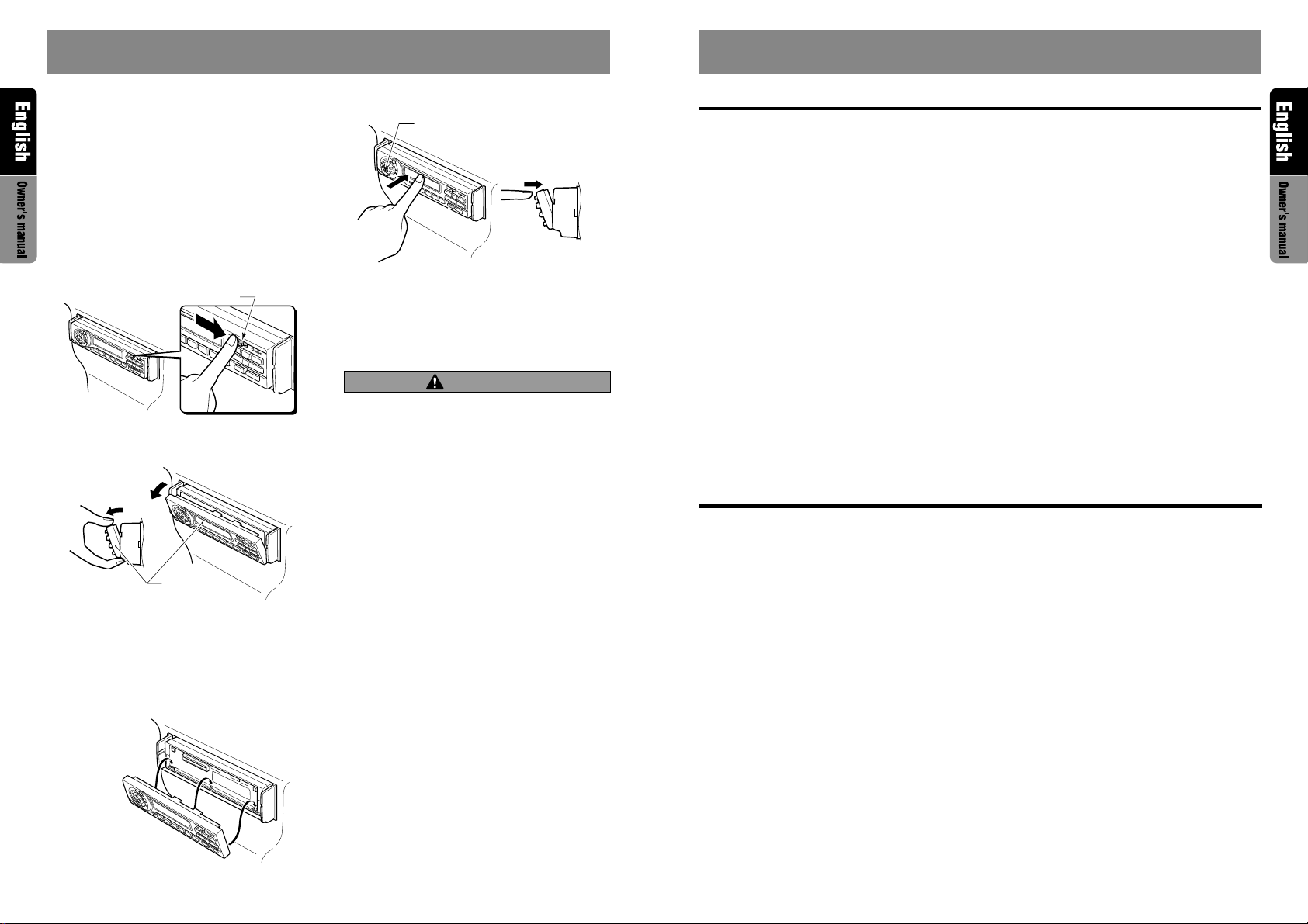
Removing the DCP
1. Turn the power off.
2. Deeply push in the DCP RELEASE lever 6
to release the DCP/Operation Panel.
DCP/RALEASE lever
3. Pull the DCP toward you and remove it.
DCP/Operation Panel
Attaching the DCP
1. Hold the DCP/Operation Panel with its rear
side facing the main unit and, as shown in
the figure below, put the lower edge of the
panel onto the corresponding edge of the main
unit.
2. Lock the DCP/Operation Panel at the upper
center until a click is heard.
POWER button
3. Press the power button 1 to turn on the
power .
∗ The unit will not accept any key inputs for 1
second after the DCP has been reattached.
CAUTION
• The DCP can easily be damaged by shocks.
After removing it, be careful not to drop it
or subject it to strong shocks.
• If the Operation Panel is kept open, the DCP
may drop due to vibration of the car. This
results in damage to the DCP. So close the
Operation Panel or remove the DCP to store
into the case.
• The connector connecting the main unit and
the DCP is an extremely important part. Be
careful not to damage it by pressing on it
with fingernails, screwdrivers, etc.
Note:
• If the DCP is dirty, wipe off the dirt with a soft, dry
cloth only.
LCD panel/Generalities
For a longer service life, be sure to read the following cautions.
•
Be sure to store the LCD panel inside the
main unit when parking the car outdoors for
long period of time. The LCD panel will operate properly in a temperature range of 0 to
60°C.
• Don’t allow any liquids on the set from drinks,
umbrellas etc. Doing so may damage the internal circuitry.
• Do not disassemble or modify the set in any
way. Doing so may result in damage.
• Do not draw the LCD panel out and use it as
a tray. Also, subjecting the LCD panel to
shocks may result in breakage, deformation
or other damage.
• Do not let cigarettes burn the display. Doing
so may damage or deform the cabinet.
• If a problem should occur, have the set inspected at your store of purchase.
• Do not insert objects or poke in the space between the LCD panel and the main unit when
the panel is tilted.
• Do not place anything on the display when
the panel is tilted.
• The remote controller may not work if the remote control sensor is exposed to direct sunlight.
• In extremely cold weather, the display movement may slow down and the display may
darken, but this is not a malfunction. The display will work normally when the temperature
increases.
• Small black and shiny spots inside the LCD
panel are normal for LCD products.
• The LCD panel may stop temporarily when it
opens or closes, when the engine stops or
when it is cold.
Cleaning
• Cleaning the cabinet
Use a soft, dry cloth and gently wipe off the dirt.
For tough dirt, apply some neutral detergent
diluted in water to a soft cloth, wipe off the dirt
gently, then wipe again with a dry cloth.
Do not use benzene, thinner, car cleaner, etc.,
as these substances may damage the cabinet
or cause the paint to peel. Also, leaving rubber
or plastic products in contact with the cabinet
for long periods of time may cause stains.
• Cleaning the LCD panel
The LCD panel tends to collect dust, so wipe it
off occasionally with a soft cloth. The surface is
easily scratched, so do not rub it with hard objects.
VRX610 1514 VRX610
Page 9
8. OPERATIONS
Basic Operations
CAUTION
When the unit is turned on, starting and stopping the engine with its volume raised to the
maximum level may harm your hearings. Be
careful about adjusting the volume.
Note:
• Use this unit after starting the engine.
Turning on and off the power
Note:
• Be careful about using this unit for a long time without running the engine. If you drain the car’s battery too far, you may not be able to start the engine and this can reduce the service life of the
battery.
1. Press the POWER button 1.
2. The illumination and display on the unit light
up. The unit automatically remembers its last
operation mode and will automatically switch
to display that mode.
3.
Press and hold the POWER button 1 for 1 second or longer to turn off the power for the unit.
Note:
• About the “SYSTEM CHECK”
The confirmation of connected equipment must be
performed for this unit only when the wiring connection is complete and power is turned on to the
unit first. When the power is supplied, “SYSTEM ”
and “PUSH PWR” appear alternately in the display. Press the POWER button 1, the system
check starts inside the unit. When “COMPLETE”
appears, press once again the POWER button 1.
Selecting a mode
1. Press the FUNC button 1 to change the mode
of operation.
2. Each time you press the FUNC button 1, the
mode of operation changes in the following
order:
Radio mode ➜ CD changer mode ➜ MD
changer mode ➜ TV mode ➜ Radio mode...
∗ External equipment not connected with CeNET
is not selected.
Note: Be sure to read this chapter referring to the front diagrams of
chapter “2. CONTROLS” on page 5 (unfold).
Adjusting the volume
Operate the VOLUME button 2 in the direction
of the arrows
volume;
ww
w: Increases the volume.
ww
zz
z: Decreases the volume.
zz
∗ The volume level indicated in the display is in a
range from 0 (minimum) to 33 (maximum).
ww
w (up) or
ww
zz
z (down) to adjust the
zz
CAUTION
While driving, keep the volume at a level at
which external sounds can be heard.
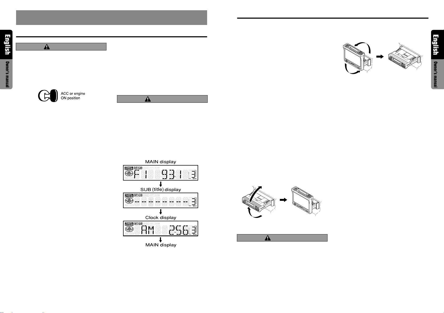
Switching the display
When the panel is closed:
Press the DISP bu t ton @to select the desired display.
Each time you press the DISP button @, the display switches in the following order:
Notes:
• Once selected, the preferred display becomes the
default display. When a function adjustment such
as volume is made, the display momentarily
switches to that function’s display, then returns
back to the preferred display several seconds after the adjustment.
•
If a title has been input, it is shown in the SUB display. If no title has been input, “---------” appears in
the display. To input a title, refer to the subsection
“Entering titles” in “Other Functions” section.
• Some special characters of the title, will not be
displayed on the Information Panel of the DCP. In
this case, those characters will only be left blank.
Showing a mode display
When the panel is open:
Press the TITLE button ( to show the Title List
display. In the Title List display, the titles of items
stored in the PRESET buttons # 1 to 6 are listed.
∗ For detailed information, refer to the section “Title
list play”.
Opening and turning the display
Notes:
• Do not place any object on the open display.
• Do not drop any object on the movable part.
• Do not expose the display to shocks.
1. Press the OPEN button ! to open the Color
LCD display ¥.
∗ If the Color LCD display ¥ is left horizontally
in the open position for 10 seconds or longer,
it is automatically drawn in.
2. Turn the Color LCD display ¥ upwards to a
good view angle.
When the monitor is turned upwards, a picture appears in the display. The Information
Panel 4 display disappears.
CAUTION
Do not turn the display unless it is completely
open.
When adjusting the angle of the display be
careful no to let your fingers get caught by
the panel or instrument panel of the vehicle.
Basic Operations
3. To store the Color LCD display ¥ in the source
unit, turn it to the horizontal position until a
click is heard.
Turning on and off the monitor
Pressing the DISP button @ turns the monitor
on and off.
∗ When a button is pressed or during security moni-
toring, the monitor-off mode is canceled.
Mute
Each time you press the MUTE button$, mute
is turned on and off.
“MUTE” appears when mute is turned on.
Setting the Z-enhancer
This unit comes with 3 types of sound tone effect
stored in memory. Select the one you prefer.
∗ The factory default setting is “Z-EHCR OFF”.
When a Z-enhancer comes on (1-3), “Z-EHCR”
appears in the display.
•“Z-EHCR 1” (Z-Enhancer 1):
Setting emphasizing bass.
•“Z-EHCR 2” (Z-Enhancer 2):
Setting emphasizing treble.
•“Z-EHCR 3” (Z-Enhancer 3):
Setting emphasizing bass and
treble.
•“Z-EHCR OFF” (Z-Enhancer off):
Neither bass nor treble are emphasized by the Z-enhancer.
Note:
• Incapable of operation when connecting DSP
(DPH7500z/7700z).
VRX610 1716 VRX610
Page 10

Basic Operations
Basic Operations
When the panel is closed:
Each time you press the Z-EHCR button 9, the
tone effect changes in the following order:
“Z-EHCR 1” ➜ “Z-EHCR 2” ➜ “Z-EHCR 3” ➜
“Z-EHCR OFF” ➜ “Z-EHCR 1”...
When the panel is open:
1. Press the A-M button & to change into the
AUDIO-MODE display.
2. Operate the JOYSTICK ¡ upward or downward to select “Z-EHCR”. Press the ENT at
the center of the JOYSTICK ¡ to change into
the Z-enhancer selecting display.
3. Operate the JOYSTICK ¡ upward or downward to select out of:
“TYPE 1” (Z-Enhancer 1) “TYPE 2” (Z-Enhancer 2) “TYPE 3” (Z-Enhancer 3)
“OFF” (Z-Enhancer off),
and press the ENT at the center of the JOYSTICK ¡ to set a desired Z-enhancer.
4. When the setting is finished, operate the JOY STICK ¡ rightward or leftward to move the
cursor to the “MENU”. Then press the ENT at
the center of the JOYSTICK ¡ to return to
the AUDIO-MODE display.
∗
T o return from the AUDIO-MODE display to the
STANDARD display, press the A-M button
once again.
&
Adjusting the Z-enhancer
Note:
• This function is enabled only when the panel is
open.
1. Press the A-M button & to change into the
AUDIO-MODE display.
2.
Operate the JOYSTICK ¡
ward
to select “Z-EH LVL” level. Press
at the center of the JOYSTICK ¡
into the Z-enhancer adjusting
3. Operate the
JOYSTICK
ward to adjust the Z-enhancer level.
∗ When Z-Enhancer 1 is selected, you can adjust
the bass in the range of ±2.
∗ When Z-Enhancer 2 is selected, you can adjust
the treble in the range of ±2.
∗ When Z-Enhancer 3 is selected, you can adjust
the bass and treble in the range of ±2.
4. When the adjustment is finished, operate the
JOYSTICK¡ rightward or leftward to move
the cursor to “MENU”. Then press the ENT at
the center of the JOYSTICK ¡ to return to
the AUDIO-MODE display.
upward or down-
the ENT
to change
display
.
¡ upward or down-
Adjusting the bass and treble
Notes:
• This function is enabled only when the panel is
open.
• This function can be adjusted only when the Zenhancer is OFF.
1. Press the A-M button & to change into the
AUDIO-MODE display.
2. Operate the JOYSTICK ¡ upward or downward to select “BAS/TRE”. Then press the
ENT at the center of the JOYSTICK ¡ to
change into the BASS/TREBLE adjusting display.
3. Operate the JOYSTICK ¡ rightward or leftward to adjust the “BASS” or “TREBLE”.
4. Operate the JOYSTICK ¡ upward or downward to adjust a level (adjustment range: from
-6 to 6).
5. When the adjustment is finished, operate the
JOYSTICK ¡ rightward or leftward to move
the cursor to “MENU”. Then press the ENT at
the center of the JOYSTICK ¡ to return to
the AUDIO-MODE display.
Adjusting the balance and fader
Note:
• This function is enabled only when the panel is
open.
1. Press the A-M button & to change into the
AUDIO-MODE display.
2. Operate the JOYSTICK ¡ upward or downward to select “BAL/FAD”. Then press the
ENT at the center of the JOYSTICK ¡ to
change into the BAL/FAD adjusting display.
3. Operate the JOYSTICK ¡ rightward or leftward to select “BALANCE” or “FADER”.
4.
Operate the JOYSTICK ¡ upward or downward to make an adjustment.
Adjusting range of the balance: L13 to R13
Adjusting range of the fader: front 12 / rear 12
5. When the adjustment is finished, operate the
JOYSTICK ¡ rightward or leftward to move
the cursor to “MENU”. Then press the ENT at
the center of the JOYSTICK ¡ to return to
the AUDIO-MODE display.
Turning on/off the loudness
The loudness effect emphasizes the bass and
treble to create a natural sound tone. When you
are listening to music at a low volume, it is recommended to use the loudness effect.
∗ This function is enabled only when the panel is
open.
1. Press the A-M button & for 1 second or longer
to select Loudness ON. The “LD” indicator
lights in the display.
2. Press the A-M button & for 1 second or longer
to select Loudness OFF. The “LD” indicator
goes off.
Note:
•
When using a sold separately digital sound processor
(DPH7500z/7700z), a feature called auto loudness is
selected. This function is different from the loudness
effect. For further details on the auto loudness feature,
refer to the subsection “Output adjustment of auto
loudness, subwoofer and playback band”.
VRX610 1918 VRX610
Page 11

Radio Operations
Radio Operations
FM reception
For enhanced FM performance the
tuner includes signal actuated stereo control, Enhanced Multi AGC, Impulse noise reduction curcuits
and Multipath noise reduction circuits.
Changing the reception area
This unit is initially set to USA frequency intervals
of 10kHz for AM and 200kHz for FM. When using it
outside the USA, the frequency reception range
can be switched to the intervals below.
● Setting the reception area
While pressing DISP button
press and hold the number “6” of the PRESET
buttons
#
tion area switches from inside the USA to outside the USA or from outside the USA to inside the USA.
∗ Any station preset memories are lost when the
reception area is changed.
for 2 seconds or longer, the recep-
@
, each time you
Listening to the radio
1. Press the FUNC button 1 and select the RADIO mode.
2. Press the BAND button % and select the radio band. Each time the button is pressed,
the radio reception band changes in the following order:
FM1 ➜ FM2 ➜ FM3 ➜ AM ➜ FM1...
3.
Press the right or left side of the SEARCH button 2
to tune in the desired station.
Tuning
There are 3 types of tuning mode available, seek
tuning, manual tuning and preset tuning.
Seek tuning
1. Press the BAND button % and select the desired band. (FM or AM)
∗ If “MANU” is lit in the display (or when the panel
is closed, if the indicator “SRCH” is not lit) press
and hold the BAND button % for 1 second or
longer. “MANU” in the display goes off (or when
the panel is open the indicator “SRCH”
lights)and seek tuning is now available.
2. Press the right or left side of SEARCH button
®
2 to automatically seek a station.
When the right side of SEARCH button 2 is
pressed, the station is sought in the direction
of higher frequencies; if the left side of
SEARCH button 2 is pressed, the station is
sought in the direction of lower frequencies.
Manual tuning
There are 2 ways available: Quick tuning and step
tuning.
When you are in the step tuning mode, the frequency changes one step at a time. In quick tuning mode, you can quickly tune the desired frequency.
1. Press the BAND button % and select the desired band. (FM or AM)
∗ If “MANU” is not lit in the display (or when the
panel is closed, if the indicator “SRCH” is lit),
press and hold the BAND button %for 1 second or longer. “MANU” appears in the display
(or when the panel is closed, the indicator
“SRCH” goes off) and manual tuning is now
available.
2. Tune into a station.
● Quick tuning:
Press and hold the right or left side of the
SEARCH button 2 for 1 second or longer to
tune in a station.
● Step tuning:
Press the right or left side of
ton 2 to manually tune in a station.
the SEARCH but-
Recalling a preset station
A total of 24 preset positions (6-FM1, 6-FM2, 6FM3, 6-AM) exists to store individual radio stations in memory. Pressing the corresponding
PRESET buttons # recalls the stored radio frequency automatically.
1. Press the BAND buttons % and select the
desired band. (FM or AM)
2. Press the corresponding PRESET buttons #
to recall the stored station.
∗ Press and hold one of the PRESET buttons #
for 2 seconds or longer to store that station
into preset memory.
Manual memory
1. Press the BAND button % and select the desired band. (FM or AM)
2. Select the desired station with seek tuning,
manual tuning, or preset tuning.
3. Press and hold one of the PRESET buttons
# for 2 seconds or longer to store the current station into preset memory.
Auto store
Auto store is a function for storing up to 6 stations that are automatically tuned in sequentially.
If 6 receivable stations cannot be received, a previously stored station remains unoverwritten at
the memory position.
1. Press the BAND button % and select the desired band. (FM or AM)
2. Press and hold the PS/AS button 5 for 2 seconds or longer. The stations with good reception are stored automatically to the preset
channels.
Preset scan
Preset scan receives the stations stored in preset memory in order. This function is useful when
searching for desired station in memory.
1. Press the PS/AS button 5.
2. When the desired station is tuned in, press
the PS/AS button 5 again to continue receiving that station.
Note:
• Be careful not to press and hold PS/AS button
for 2 seconds or longer, otherwise the auto store
function engages and the unit starts storing stations.
Instant station recall (ISR)
Instant station recall is a special radio preset that
instantly accesses a favorite radio station at a
touch of a button. The ISR function even operates with the unit in other modes.
● ISR memory
1. Select the station that you wish to store in ISR
memory.
2. Press and hold ISR button 0 for 2 seconds
or longer.
● Recalling a station with ISR
In any mode, press ISR button 0 to turn on the
radio function and tune the selected radio station. “ISR” appears in the display . Press ISR button 0 again to return to the previous mode.
5
VRX610 2120 VRX610
Page 12

CD Changer Operations
CD Changer Operations
CD changer functions
When an optional CD changer is connected
through the CeNET cable, this unit controls all
CD changer functions. This unit can control a total
of 2 changers (MD and/or CD).
Press the FUNC button 1 and select the CD
changer mode to start play. If 2 CD changers are
connected, press the FUNC button 1 to select
the CD changer for play.
∗ If “NO MAG” appears in the display, insert the
magazine into the CD changer. “LOADING” appears in the display while the player loads (checks)
the magazine.
∗ If “NO DISC” appears in the display, eject the
magazine and insert discs into each slot. Then,
reinsert the magazine back into the CD changer.
CAUTION
CD-ROM discs cannot be played in the CD
changer.
Pausing play
1. Press the PLAY/PAUSE button 3 to pause
play. “PAUSE” appears in the display.
2. To resume play, press the PLAY/PAUSE button 3 again.
Displaying CD titles
This unit can display title data for CD-text CDs
and user titles input with this unit.
Each time you press and hold the DISP button
@ for 1 second or longer , the title display changes
in the following order.
When the panel is closed:
User title (disc) ➜ CD-text title (disc) ➜ CD-text
title (track) ➜ User title (disc)...
When the panel is open:
User title (disc) ➜ CD-text title (disc & track) ➜
User title (disc)...
Note:
• If the CD playing is not a CD-text CD or no user
title has been input, “----------” appears in the display.
● Scrolling a CD-text title
When a CD-text title is longer than 16 characters (8 characters when the panel is closed), you
can scroll the display as follows.
When the panel is closed:
1. Display the CD-text title (disc or track).
2. Press and hold the BAND button % for 1 second or longer. The titles scroll.
When the panel is open:
1. Display the CD-text title (disc & track).
2. Press and hold the TITLE button ( for 1 second or longer to scroll the disc title.
3. To scroll the track title,
longer the TITLE button (
after
scrolling the disc title.
Notes:
• If the disc title is shorter than 16 characters, the
track titles begin to scroll immediately.
• If the track title is shorter than 16 characters, the
track titles does not scroll.
press
for 1 second or
within 30 seconds
Selecting a CD
Each of the DIRECT buttons # corresponds to
a disc loaded into the magazine.
● Selecting a disc from 1 to 6
Press the corresponding DIRECT buttons (1 to
6) #to select the desired disc.
● Selecting a disc from 7 to 12 (only when a
12 disc CD changer is used.)
Press the corresponding DIRECT buttons (7 to
12) # for 1 second or more, then select the
desired disc.
Selecting a track
● Track-up
1. Press the right side of the SEARCH button
2 to move ahead to the beginning of the next
track.
2. Each time you press the right side of the
SEARCH button 2, the track advances ahead
to the beginning of the next track.
● Track-down
1. Press the left side of the SEARCH button 2
to move back to the beginning of the current
track.
2. Press the left side of the SEARCH button 2
twice to move to the beginning of the previous track.
Fast-forward/Fast-backward
● Fast-forward
Press and hold the right side of the SEARCH
button 2 for 1 second or longer.
● Fast-backward
Press and hold the left side of the SEARCH button 2 for 1 second or longer.
Top function
The top function plays from the first track (track
No. 1) of the disc.
● When playing a disc 1 to 6
Press the DIRECT buttons #(1 to 6) with the
same number as the CD playing.
● When playing a disc 7 to 12 (only when a 12
disc CD changer is used.)
Press the DIRECT buttons # (7 to 12) with the
same number as the CD playing for 1 second or
longer.
Scan play
The scan play locates and plays the first 10 seconds of each track on a disc automatically. This
function continues on the disc until it is cancelled
or the mode is changed.
∗ The scan play is useful when you want to select a
desired track.
1. Press the SCN button 5 to start scan play.
2. Press the SCN button 5 again to cancel the
scan play. Current track continues to play.
Disc scan play
The disc scan play locates and plays the first 10
seconds of the first track on each disc in the currently selected CD changer. This function continues automatically until it is cancelled or the
mode is changed.
∗ The disc scan play is useful when you want to se-
lect a desired CD.
1. Press the SCN button 5 for 1 second or
longer to start disc scan play.
2. Press the SCN button 5 again to cancel disc
scan play. Normal disc play continues on the
current track.
Repeat play
The repeat play continuously plays the current
track. This function continues automatically until
it is cancelled or the mode is changed.
1. Press the RPT button 7, to make repeat play
starts. “RPT” lights in the display.
2. To cancel repeat play, press the RPT button
7 again. “RPT” goes off from the display and
the unit returns to normal play.
Disc repeat play
After all tracks in the current disc have been
played, the disc repeat play automatically replays
the current disc over from the first track. This function continues automatically until it is cancelled
or the mode is changed.
1. When you press the RPT button 7for 1 second or longer, disc repeat play starts. “D-RPT”
lights in the display.
2. To cancel disc repeat play, press the RPT
button 7 again. “D-RPT” goes off from the
display and the unit returns to normal play
from the track being played.
Random play
The random play selects and plays individual
tracks on the disc in no particular order. This function continues automatically until it is cancelled
or the mode is changed.
1. When you press the RDM button 8, random
play starts. “RDM” lights in the display.
2. To cancel random play, press the RDM button 8 again. “RDM” goes off from the display and the unit returns to normal play.
Disc random play
The disc random play selects and plays individual
tracks or discs automatically in no particular order. This function continues automatically until it
is cancelled or the mode is changed.
1. When you press the RDM button 8 for 1 second or longer, disc random play starts. “D-
RDM” lights in the display.
2. To cancel disc random play, press the RDM
button 8 again. “D-RDM” goes off from the
display and the unit returns to normal play
from the track being played.
VRX610 2322 VRX610
Page 13

MD Changer Operations
MD Changer Operations
MD changer functions
When an optional MD changer is connected
through the CeNET cable, this unit controls all
MD changer functions. This unit can control a
total of 2 changers (MD and/or CD).
Press the FUNC button 1 and select the MD
changer mode to start play. If 2 MD changers
are connected, press the FUNC button 1 to select the MD changer for play.
∗ If “NO DISC” appears in the display , load MDs into
the MD changer.
Pausing play
1. Press the PLAY/PAUSE button 3 to pause
play. “PAUSE” appears in the display.
2. T o resume play, press the PLAY/PAUSE button 3 again.
Switching disc titles and track
titles
This unit can display disc titles and track titles
already entered on MDs. Titles up to 128 characters long can be displayed by scrolling the
titles.
∗ Titles cannot be entered for MDs with this unit.
When the panel is closed:
1. Press the DISP button @ to show the SUB
display . The disc title or track title is displayed.
2. Each time you press and hold the DISP button @ for 1 second or longer, the display
toggles between the disc title and the track
title.
When the panel is open:
Both disc and track titles are displayed.
Scrolling titles
When a title is longer than 16 characters (or 8
characters if the panel is closed), you can scroll
through it with the following operation.
When the panel is closed:
1. Display the MD title (disc or track).
2. Press the BAND button % for 1 second or
longer. The display scrolls through the title.
When the panel is open:
1. Press the TITLE button ( for 1 second or
longer to scroll through the disc title.
2. To scroll the track title,
longer the TITLE button (
after
scrolling the disc title.
press
for 1 second or
within 30 seconds
Notes:
• When the disc title is within 16 characters, the title
is scrolled immediately.
• If the track title is shorter than 16 characters, the
track titles does not scroll.
Selecting an MD
Each of the DIRECT buttons # corresponds to
an MD loaded into the MD changer.
Press the DIRECT buttons # (1 to 6) and select
the desired MD.
Selecting a track
● Track-up
1. Press the right side of the SEARCH button
2 to move ahead to the beginning of the next
track.
2. Each time you press the right side of the
SEARCH button 2, the track advances ahead
to the beginning of the next track.
● Track-down
1. Press the left side of the SEARCH button 2
to move back to the beginning of the current
track.
2. Press the left side of the SEARCH button 2
twice to move to the beginning of the previous track.
Fast-forward/Fast-backward
● Fast-forward
Press and hold the right side of he SEARCH button 2 for 1 second or longer.
● Fast-backward
Press and hold the left side of he SEARCH button 2 for 1 second or longer.
Top function
The top function plays from the first track (track
No. 1) of the disc.
Press the DIRECT buttons # (1 to 6) with the
same number that the MD playing.
∗ If an MD is not loaded in a slot of the MD changer,
pressing the DIRECT buttons # corresponding
to its disc number is invalid.
Scan play
The scan play locates and plays the first 10 seconds of each track on a disc automatically. This
function continues on the disc until it is cancelled
or the mode is changed.
∗ The scan play is useful when you want to select a
desired track.
1. When you press the SCN button 5, scan play
starts.
2. Press the SCN button 5 again to cancel the
play. Current track continues to play.
Disc scan play
The disc scan play locates and plays the first 10
seconds of the first track on each disc in the currently selected MD changer. This function continues automatically until it is cancelled or the
mode is changed.
∗ The disc scan play is useful when you want to
select a desired MD.
1. When you press the SCN button 5 for 1 second or longer, disc scan play starts.
2. To cancel disc scan play , press the SCN button 5 again. Normal disc play continues on
the current track.
Repeat play
The repeat play continuously plays the current
track. This function continues automatically until
it is cancelled or the mode is changed.
1. When you press the RPT button 7, repeat
play starts. “RPT” lights in the display.
2. To cancel repeat play, press the RPT button
7 again. “RPT” goes off from the display and
the unit returns to normal play.
Disc repeat play
After all the tracks on the current disc have been
played, the disc repeat play automatically replays
the current disc over from the first track. This function continues automatically until it is cancelled
or the mode is changed.
1. When you press the RPT button 7 for 1 second or longer, disc repeat play starts. “D-RPT”
lights in the display.
2. To cancel disc repeat play, press the RPT
button 7 again. “D-RPT” goes off from the
display and the unit returns to normal play
from the track being played.
Random play
The random play selects and plays individual
tracks on the disc in no particular order. This function continues automatically until it is cancelled
or the mode is changed.
1. When you press the RDM button 8, random
play starts. “RDM” lights in the display.
2. To cancel random play, press the RDM button 8 again. “RDM” goes off from the display and the unit returns to normal play.
Disc random play
The disc random play selects and plays individual
tracks or discs automatically in no particular order. This function continues automatically until it
is cancelled or the mode is changed.
1. When you press the RDM button 8 for 1 second or longer, random play starts. “D-RDM”
lights in the display.
2. To cancel random play, press the RDM button 8 again. “D-RDM” goes off from the display and the unit returns to normal play from
the track being played.
VRX610 2524 VRX610
Page 14

TV Operations
TV Operations
TV functions
When an optional TV tuner is connected through
the CeNET cable, this unit controls all TV tuner
functions. To watch TV requires a TV tuner.
W ARNING
For your safety, the driver should not watch
the TV or operate the controls while driving. Please note that watching and operating the TV while driving are prohibited by
law in some countries.
Watching TV
Notes:
• For your safety, this unit has a safety function which
turns off the picture when the car is moving, so
only the audio can be heard. The picture can only
be watched when the car is stopped and the parking break is applied.
1. Press the FUNC button 1 and select the TV
mode.
2. Press the BAND button % to select the desired TV band (TV1 or TV2). Each time the
button is pressed, the input selection toggles
between TV1 and TV2.
3. Press the right or left side of the SEARCH
button 2 to tune in the desired TV station.
Watching a video
The TV tuner has a VTR input terminal to which
1 external device can be connected. Connect a
12V video cassette player (VCP) or video cassette recorder (VCR) to the TV tuner input terminal.
1. Press the RDM button 8 and select the VTR.
2. T o return to the TV broadcast, press the RDM
button 8 again.
Tuning
There are 3 types of tuning mode available, seek
tuning, manual tuning and preset tuning.
Seek tuning
1. Press the BAND button % and select the desired TV band (TV1 or TV2).
∗ If “MANU” is lit in the display (or when the panel
is closed, if the indicator “SRCH” is not lit),
press and hold the BAND button % for 1 second or longer. “MANU” in the display goes off
(or when the panel is closed, the indicator
“SRCH” lights) and seek tuning is now available.
2. Press the right or left side of the SEARCH
button 2 to automatically seek a station.
Press the right side of the SEARCH button
2 to automatically tune up the frequency
band to the next available TV station; press
the left side to automatically tune down.
Manual tuning
There are 2 ways available: Quick tuning and step
tuning. When you are in the step tuning mode,
the frequency changes one step at a time. In
quick tuning mode, you can quickly tune the desired frequency.
1. Press the BAND button % and select the desired band. (TV1 or TV2)
∗ If “MANU” is not lit in the display (or when the
panel is closed, if the indicator “SRCH” is lit),
press and hold the BAND button % for 1 second or longer. “MANU” appears in the display
(or when the panel is closed, the indicator
“SRCH” goes off) and manual tuning is now
available.
2. Tune into a station.
● Quick tuning:
Press and hold the right or left side of the
SEARCH button 2 for 1 second or longer to tune
in a station.
● Step tuning:
Press the right or left side of the SEARCH button 2 to manually tune in a station.
Note:
• Manual tuning is cancelled if you do not operate
the unit for 7 seconds longer.
Recalling a preset station
A total of 12 TV stations can be stored (6-TV1
and 6-TV2). This allows you to select your favorite TV stations and store them in memory for later
recall.
1. Press the BAND button % and select the desired TV band. (TV1 or TV2)
2. To recall a stored TV station, press the desired PRESET buttons # to select that station.
∗ Press and hold one of the PRESET buttons #
for 2 seconds or longer to store the current station into the preset memory.
Manual memory
1. Select the desired station with seek tuning,
manual tuning or preset tuning.
2. Press and hold one of the PRESET buttons
# for 2 seconds or longer to store the current station to that preset memory.
Auto store
Auto store selects 6 TV stations automatically and
stores each one into a preset memory.
If there are not 6 stations with good reception,
stations previously stored in memory remain and
only the strong stations are stored into memory.
1. Press the BAND button % and select the desired TV band. (TV1 or TV2)
2. Press and hold the AS/PS button 5 for 2 seconds or longer. The stations with good reception are automatically stored to the PRESET
buttons # .
Preset scan
Preset scan allows the user to view each preset
position before it automatically advances to the
next preset. This function is useful for searching
for desired TV station in memory.
1. Press the AS/PS button 5.
2. When the desired channel is received, press
the AS/PS button 5 again.
Switching the VTR system between
NTSC and PAL
∗ This function is enabled only when the panel is
open.
Switch to the VTR mode you use.
1. Press the ADJ button * to switch to the adjustment selection display.
2. Operate the JOYSTICK ¡ upward or downward to move the cursor to “VTR N/P”.
3. Operate the JOYSTICK ¡ rightward or leftward to move the cursor to select “NTSC” or
“PAL”.
4. Press the ENT at the center of the JOYSTICK
¡ to set the selected VTR mode.
Setting the TV diver
∗ This function is enabled only when the panel is
open.
∗ Normally use the TV diver with the “ON” position.
You can change the reception setting for the TV
antenna connected to the TV tuner.
1. Press the ADJ button * to switch to the adjustment selection display.
2. Operate the JOYSTICK ¡ upward or downward to select “TV DIVER”.
3. Operate the JOYSTICK ¡ rightward or leftward to select “ON” or “OFF” and press the
ENT at the center of the JOYSTICK ¡ to set
the selected reception setting.
● ON:
Sets reception emphasizing the visual.
● OFF:
Sets the diver setting to OFF.
4. Press the ADJ button * return to the previous mode.
VRX610 2726 VRX610
Page 15

TV Operations
Adjusting the brightness and tone
of color
Notes:
• This operation is available only when the car is
stopped and the parking brake is applied.
• This function is not available when the display is
stored.
• The HUE setting can be adjusted only when the
NTSC mode is selected.
1. Press the ADJ button * to switch to the ad-
justment selection display.
2. Operate the JOYSTICK ¡ upward or down-
ward to select the option “MONI ADJ” (by
moving the cursor).
3. Press the ENT at the center of the JOYSTICK
¡.
4. Operate the JOYSTICK ¡ rightward or left-
ward to select “BRIGHT”,“COLOR” or “HUE”
(by moving the cursor).
● “BRIGHT“:
Adjust the brightness of the display.
● “COLOR“:
Adjusts the color saturation.
● “HUE“:
Adjusts the tone of color (red is emphasized
or green is emphasized.)
5. Operate the JOYSTICK ¡ upward or down-
ward to adjust a level.
6. When the adjustment is made, operate the
JOYSTICK ¡ rightward or leftward to move
the cursor to “MENU”. Then press the ENT at
the center of the JOYSTICK ¡ to return to
the adjustment selection display.
Changing over TV display size
∗ This function is available only when the panel is
open.
Press the WIDE button 7 to change over the
TV display size. Each time you press the
WIDE button 7, the TV display size changes
in the following order:
“NORMAL” ➜ “WIDE” ➜ “F. WIDE” ➜ “CIN-
EMA” ➜ “NORMAL”
● “NORMAL”: (normal display)
There is a black area at both right and left
ends of a display. In case of normal TV broadcasting (4:3), the image can be shown without being cut or deformed.
● “WIDE”: (wide mode)
The image at right and left ends in a display
elongates horizontally.
● “F. WIDE”: (full wide mode)
The whole image elongates horizontally.
● “CINEMA”: (cinema mode)
The image at both top and bottom in a dis-
play disappears.
Notes:
• When a normal 4:3 size image, not being a wide
one, is viewed by displaying it fully on a wide TV
display in a wide mode or a full-wide mode, a part
of the peripheral image will be lacking or deformed.
In deference to the intention of producer, an original image can be viewed in a normal mode.
• During superimposed display, it becomes a fullwide mode.
Rear Vision Camera
Monitoring the rear vision camera
The rear vision camera can be connected to this
unit. For the power supply of the camera, mount
the power box sold separately (CAA-147).
Notes:
• This function is not available when the display is
stored.
Operation of External Visual
Devices (VISUAL Mode)
External visual devices such as DVD and VTR
devices can be connected to the DIN 8-pin terminal, and the image and sound can then be
played using VISUAL mode.
Notes:
• While driving, the image of the VISUAL Mode is
turned OFF and only sound is played.
• Images can only be played when the vehicle is
stationary with the parking brake ON.
1. With the panel open, push VISUAL button )
to switch from radio, TV, CD/MD changer
mode to VISUAL mode.
2. T o exit VISUAL Mode and return to the previous mode, press VISUAL button ) again.
∗ The image format played in VISUAL mode can
be set to NTSC or PAL format. The setting
method is the same as for the TV. Please refer
to the TV explanation.
∗ In VISUAL mode, the picture quality can be ad-
justed. The setting method is the same as for
the TV. Please refer to the TV explanation.
Switching to Composite
Screen
∗ The display panel can be switched to a composite
screen to lock the monitor or to view a video CD.
1. When the panel is open, press the OPEN/
M.LOCK button ! to switch to the composite screen.
2. When the panel is open and the composite screen
is shown, press the OPEN/M.LOCK button
! again to return to the previous screen.
VRX610 2928 VRX610
Page 16

Other Functions
Other Functions
Always turning on the button
illumination on the operation panel
Note:
• The following operation is enabled when the panel
is open.
The button illumination on the operation panel
when the display is turned upward, can be
switched between “ON” and “OFF”.
● “ON”: Button illumination on the operation
panel turns on for 5 seconds;
● “OFF” : Button illumination is always on when
the power is turned on;
1.
When the panel is open, press the ADJ button
£ to show the adjustment selection display.
2. Operate the JOYSTICK ¡ upward or downward and select “AUTO ILL” to show “ON”
and “OFF” in the menu bar.
3. Operate the JOYSTICK ¡ rightward or leftward to select either position to be set and
press the ENT at the center of the JOYSTICK
¡ for setting.
4. Press the ADJ button * to return to the previous mode.
∗
T o set “ON” again, switch “OFF” to “ON” manually.
Entering titles
Titles up to 10 characters long can be stored in
memory and displayed. The numbers of titles that
can be entered for each mode are as follows.
Mode Number of titles
Radio mode 30 titles
TV mode 15 titles
CD changer mode Number of titles
CDC655z connected 60 titles
CDC655Tz connected 100 titles
CDC1255z connected 50 titles
∗ You cannot enter titles with the unit in Seek, Pre-
set Scan, Auto store (TUNER, TV), Scan, Repeat
or Random (CD changer, MD changer) mode. Cancel each of those operations before entering titles.
1. Press the FUNC button 1 to select the mode
you want to enter a title (CD changer or TV).
2. Select and play a CD in the CD changer or
tune in to a TV station for which you want to
enter the title.
3. If you press and hold the TITLE button ( for
1 second or longer, the display switches to
the title input mode display.
4. Operate the JOYSTICK ¡ upward or downward, rightward or leftward and move the cursor to the character to be entered. Press the
ENT at the center of the JOYSTICK ¡.
∗ When the cursor is at the lower/upper limit of
the display, operate the JOYSTICK ¡ upward
or downward, the character string of the following line appears.
“-->” : Space
“<--” : Backspace
“--I--” : Centering
5. Repeat the step 4 to enter the complete title.
6.
Press and hold the ENT at the center of the
JOYSTICK ¡ for 2 seconds or longer to store
the title into memory and cancel title input mode.
Title list play
Y ou can display a list of titles, then select the disc
or broadcast station to listen to from that list.
∗ You can not display a title list with the unit in Seek,
Preset Scan, Auto store (Tuner or TV), Scan, Repeat or Random (CD changer or MD changer)
mode. Cancel those operation modes before to
display a title list.
1. With the unit in radio, CD/MD changer, TV,
press the TITLE button (. A title list is displayed. The following functions can be carried out in a title list display.
● TUNER: A title of a channel stored in the
presets 1 to 6 or a channel number is displayed.
● CD/MD changer: DISC titles for discs 1 to
6 are displayed (By changing over a display
page in case of 12-CD changer, disc 7 to 12
can be displayed). When there is not any disc
in a changer, ”---------” is displayed.
● TV: A title of a channel stored in the pre-
sets 1 to 6 or a channel number is displayed.
2. Operate the JOYSTICK ¡ upward or downward to select one of the items 1 to 6. Press
ENT at the center of the JOYSTICK ¡ to reproduce the selected broadcast station or
disc.
∗ In case of 12-CD changer, move the cursor to
disc 6 and then operate the JOYSTICK ¡
downward to change over to a list display of
discs 7 to 12.
3. Press the TITLE button ( again to return to
the STANDARD display.
Clock Adjustment
1. Press the ADJ button * to display the adjustment selection display.
2. Move the JOYSTICK ¡ up or down to select
CLOCK, then press ENT at the center of the
JOYSTICK ¡ to display the clock adjustment
display.
3. Move the JOYSTICK ¡ left or right to select
HR or MIN, then move the JOYSTICK ¡ up
or down to adjust the time.
∗ The time is displayed in 12-hour format.
4. Pressing ENT at the center of the JOYSTICK
¡ when the cursor is above HR or MIN saves
the adjusted value in memory and simultaneously returns the display to the previous
display (adjustment selection display).
T o cancel clock adjustment before completion,
use the JOYSTICK ¡ to move the cursor to
MENU, then press ENT at the center of the
JOYSTICK ¡.
Triggered audio mute for cellular
telepones
This unit requires special wiring to mute the audio signal automatically when a cellular telephone
rings in the car.
∗ This function is not compatible wiht all cellular
telepones Contact your local authorized Clarion
dealer for information on proper installation and
compatibility.
VRX610 3130 VRX610
Page 17

DSP operations
DSP operations
DSP control function
If the DSP (DPH7500z/7700z), sold separately,
is connected to this unit using the CeNET cable,
all the functions of the DSP can be controlled.
∗ When the DSP is connected, an external ampli-
fier is required.
∗ DSP control can all be operated only when the
panel is open.
DSP functions
There are 2 modes available in DPH7500z/7700z,
standard mode and professional mode. Choose
one of them and adjust the sound field and the
sound quality.
● Functions common to each mode:
Such as auto loudness, subwoofer etc.
● Standard mode:
Adjustment using the graphic equalizer function
and the DSP function.
● Professional mode:
Adjustment using the space equalizer function
and the parametric equalizer function.
∗ When the standard mode is selected, adjustment
for the professional mode cannot be made. On
the contrary, when the professional mode is selected, adjustment for the standard mode cannot
be made.
∗ For details on functions of each mode, refer to the
owner’s manual supplied with the DPH7500z/
7700z.
∗ Hereafter the graphic equalizer is referred to as a
G.EQ, the space equalizer referred to as VSE and
the parametric equalizer referred to as P.EQ.
Operations common to each mode
Output adjustment of auto loudness,
subwoofer and playback band
1. Press the ADJ button * to switch to the adjustment selection display.
2. Operate the JOYSTICK ¡ upward or downward to select “SOUND” and press the ENT
at the center of the JOYSTICK ¡ to change
into the Sound adjustment display. In the
Sound adjustment display “A.LD LEVEL”,
“W.OUT”, “W.LPF”, “HPF”, “T.TONE” are
listed.
Operate the JOYSTICK ¡ rightward or leftward to select an item to be adjusted.
3. To make an adjustment on:
● Auto loudness adjustment
Operate the JOYSTICK ¡ upward or down-
ward to adjust an auto loudness level (0 to
10).
● Woofer out adjustment
Select woofer output out of “STEREO”,
“MONO”, or “OFF”.
Operate the JOYSTICK ¡ upward or down-
ward to select a desired item, and then press
the ENT at the center of the JOYSTICK ¡ to
set it.
● Woofer LPF adjustment
Select woofer LPF slope out of “50Hz”,
“80Hz”, “120Hz”.
Operate the JOYSTICK ¡ upward or down-
ward to select a desired item, and then press
the ENT at the center of the JOYSTICK ¡ to
set it.
● HPF adjustment
Select HPF slope out of “50Hz”, “80Hz”,
“120Hz”, or “OFF”.
Operate the JOYSTICK ¡ upward or down-
ward to select a desired item, and then press
the ENT at the center of the JOYSTICK ¡ to
set it.
● Test Tone Output
Select Test Tone Output
Operate the JOYSTICK ¡ upward or down-
ward to select a desired item, and then press
the ENT at the center of the JOYSTICK ¡ to
produce a test tone.
4. After adjustment (setting), operate the JOYSTICK ¡ rightward or leftward to move the
cursor to “MENU” and press the ENT at the
center of the JOYSTICK ¡ to return to the
adjustment selection display.
5. Press the ADJ button * again to return to
the STANDARD display.
Selecting the standard mode or the
professional mode
∗ The factory default setting is “STD”.
1.
Press the ADJ button * to switch to the adjustment selection display.
2. Operate the JOYSTICK ¡ upward or downward to select “DSF/EQ”. “STD” and “PRO”
items are displayed in the menu bar.
3. Operate the JOYSTICK ¡ rightward or leftward to select a desired mode and press the
ENT at the center of the JOYSTICK ¡ to set
the mode thus selected.
4. After setting, press the ADJ button * again
to return to the STANDARD display.
Woofer level adjustment
You can adjust an output sound level of
subwoofer.
1. Press the A-M button & to show the AUDIOMODE display.
2. Operate the JOYSTICK ¡ upward or downward to select “W-VOL” and press the ENT
at the center of the JOYSTICK ¡ to show
the woofer level adjusting display.
3. Operate the JOYSTICK ¡ upward or downward to adjust the level (0 to 14).
4. After adjustment, operate the JOYSTICK ¡
rightward or leftward to select “MENU” and
press the ENT at the center of the JOYSTICK
¡¡return to the AUDIO-MODE display.
Standard mode/Setting the listening position
Selection of listening position
1. Press the A-M button & to show the AUDIOMODE display.
2. Operate the JOYSTICK ¡ upward or downward to select “POSITION”. “SELECT" and
“DETAIL” are displayed in the menu bar.
3. Operate the JOYSTICK ¡ rightward or leftward to select “SELECT”, and press the ENT
at the center of the JOYSTICK ¡ to show
Position selecting display.
4. Operate the JOYSTICK ¡ upward or downward and press the ENT at the center of the
JOYSTICK ¡ to select a desired position.
5. Operate the JOYSTICK ¡ rightward or leftward to move the cursor to “MENU”, and press
the ENT at the center of the JOYSTICK ¡ to
return to the AUDIO-MODE display.
Detail adjustment of listening
position
1. Press the A-M button & to show the AUDIOMODE display.
2. Operate the JOYSTICK ¡ upward or downward to select “POSITION”. “SELECT" and
“DETAIL” are displayed in the menu bar.
3. Operate the JOYSTICK ¡ rightward or leftward to select “DETAIL”, and press the ENT
at the center of the JOYSTICK ¡ to show
Position Detail adjusting display.
4. Operate the JOYSTICK ¡ rightward or leftward to select “BALANCE” or “FADER”.
5. Operate the JOYSTICK ¡ upward or downward to make an adjustment.
6. Operate the JOYSTICK ¡ rightward or leftward to move the cursor to “MENU”, and press
the ENT at the center of the JOYSTICK ¡ to
return to the AUDIO-MODE display.
VRX610 3332 VRX610
Page 18

DSP operations
DSP operations
Standard mode/G.EQ operations
Note:
• The adjustment made in standard mode is not reflected in the adjustment in professional mode. Respectively, the adjustment made in professional mode
is not reflected in the adjustment in standard mode.
G.EQ effect ON/OFF
∗ The factory default setting is “ON”.
1. Press the A-M button & to show the AUDIO-
MODE display.
2. Operate the JOYSTICK ¡ upward or down-
ward to select “EQ ON/OFF”. “ON” and “OFF”
items are displayed in the menu bar.
3.
Operate the JOYSTICK ¡ rightward or leftward
to select “ON” or “OFF” and press the ENT at
the center of the JOYSTICK ¡ to set it.
4. After the setting, press the A-M button &
again to return to the STANDARD display.
Note:
• If the G.EQ effect is set to OFF, the adjustment
made in “G.EQ operations” is not reflected in the
music source.
Calling G.EQ BASIC Pattern/USER
Pattern
1. Press the A-M button & to show the AUDIO-
MODE display.
2. Operate the JOYSTICK ¡ upward or down-
ward to select “EQ MODE”. “BASIC” and
“USER” items are displayed in the menu bar.
3. Operate the JOYSTICK ¡ rightward or left-
ward to select the item thus called, and press
the ENT at the center of the JOYSTICK ¡ to
show BASIC pattern selecting display or
USER pattern selection/memory display.
4. In the Pattern selecting display, operate the
JOYSTICK ¡ rightward or leftward to select
P1 to P6, and press the ENT at the center of
the JOYSTICK ¡ to call corresponding G.EQ
pattern. In this display, pressing the No. button in correspondence to the PRESET button
# can also call the G.EQ pattern.
∗ After selecting P1 to P6 by the JOYSTICK ¡,
press ENT at the center of the JOYSTICK ¡
for 2 seconds or longer to copy the selected
pattern to the USER pattern.
∗ Operate the JOYSTICK ¡ rightward or leftward
to select “EDIT”, and press the ENT at the center of the JOYSTICK ¡ to show G.EQ adjust-
ing display, in which the properties of currently
selected pattern can be adjusted.
∗ By pressing the BAND button % in BASIC pat-
tern selecting display or USER pattern selection/memory display you can switch between
the two patterns, BASIC and USER.
5. Operate the JOYSTICK ¡ rightward or leftward to select “MENU”, and press the ENT at
the center of the JOYSTICK ¡ to return to
the AUDIO-MODE display.
Setting and storing G.EQ Properties/Memory into USER Pattern
1. Repeat the steps 1 to 3 of the previous procedure (Calling G.EQ BASIC Pattern/USER Pattern) to show BASIC pattern selecting display
or USER pattern selection/memory display.
2. Operate the JOYSTICK ¡ leftward and rightward to select “EDIT”, and press the ENT at
the center of the JOYSTICK ¡ to show the
G.EQ adjusting display.
3. When some frequency to be adjusted is selected by operating the JOYSTICK ¡ rightward or leftward in the G.EQ adjusting display,
a gain setting value at the selected frequency
is displayed.
4. Operate the JOYSTICK ¡ upward or downward to adjust the G.EQ GAIN.
∗
By pressing the
G.EQ adjusting display , the setting value for currently stored USER pattern is obtained.
5. After making adjustments to a desired pattern
by repeating the operations of items 3 and 4,
operate the JOYSTICK ¡ rightward or leftward to move the cursor to “RTN”, and press
the ENT at the center of the JOYSTICK ¡ to
change over to the BASIC/USER pattern selection/memory display.
6.
Operate the
in the BASIC/USER pattern selection/memory
display to select USER memory P1 to P6 to be
stored, and press
JOYSTICK ¡
the adjusted G.EQ pattern to the USER memory.
∗ By pressing the PRESET button # 1 to 6 for 2
seconds or longer in the G.EQ adjusting display, the G.EQ pattern can be stored in the
USER memory.
7. To set a title of the stored USER pattern, operate the JOYSTICK ¡ rightward or leftward
to select “TITLE” and press the ENT at the
center of the JOYSTICK ¡ to change into the
Title Input display.
∗For title inputting method, refer to the section
“Entering titles”.
PRESET buttons #
JOYSTICK ¡
for 2 seconds or longer to store
rightward or leftward
the ENT at the center of the
once in the
8. Operate the JOYSTICK ¡ rightward or leftward to select “MENU” and press the ENT at
the center of the JOYSTICK ¡ to change into
the AUDIO-MODE display.
Standard mode/DSF operations
DSF effect ON/OFF
∗ The factory default setting is “ON”.
1. Press the A-M button & to show the AUDIOMODE display.
2. Operate the JOYSTICK ¡ upward or downward to select “DSF ON/OFF”. “ON” and
“OFF” items are displayed in the menu bar.
3. Operate the JOYSTICK ¡ rightward and leftward to select “ON” or “OFF” and press the
ENT at the center of the JOYSTICK ¡ to set
it.
Note:
• If the DSF effect is set to OFF, the adjustment
made in “DSF operations” is not reflected in the
music source.
Calling DSF BASIC Pattern/USER
Pattern
1. Press the A-M button & to show the AUDIOMODE display.
2. Operate the JOYSTICK ¡ upward or downward to select “DSF MODE”. “BASIC 1”, “BA-
SIC 2” and “USER” items are displayed in the
menu bar.
3. Operate the JOYSTICK ¡ rightward or leftward to select the item thus called, and press
the ENT at the center of the JOYSTICK ¡ to
show BASIC pattern selecting display or
USER pattern selection/memory display.
4. In the pattern selecting display, operate the
JOYSTICK ¡ rightward or leftward to select
P1 to P6, and press the ENT at the center of
the JOYSTICK ¡ to call corresponding DSF
mode. In this display, pressing the No. button
in correspondence to the PRESET buttons #
can also call the DSF mode.
∗ After selecting P1 to P6 by operating the JOY-
STICK ¡, press the ENT at the center of the
JOYSTICK ¡ for 2 seconds or longer to copy
the selected pattern to the USER pattern.
∗ Operate the JOYSTICK ¡ rightward or left-
ward to select “EDIT”, and press the ENT at
the center of the JOYSTICK ¡ to show DSF
adjusting display, in which the properties of currently selected pattern can be adjusted.
∗ By pressing the BAND button % in BASIC pat-
tern selecting display or USER pattern selection/memory display you can switch between
the two patterns, BASIC and USER.
5. Operate the JOYSTICK ¡ rightward or leftward to select “MENU”, and press the ENT at
the center of the JOYSTICK ¡ to return to
the AUDIO-MODE display.
Setting and storing DSF Properties/
Memory into USER Pattern
1. Repeat the steps 1 to 3 of the previous procedure (Calling DSF BASIC Pattern/USER Pattern) to show BASIC pattern selecting display
or USER pattern selection/memory display.
2. Operate the JOYSTICK ¡ upward or downward to select “EDIT”, and press the ENT at
the center of the JOYSTICK ¡ to show the
DSF adjusting display.
3. Select an item to be adjusted by operating the
JOYSTICK ¡ rightward or leftward in the DSF
adjusting display.
“EF” ➜ EFFECT
“DL” ➜ DELAY
“R.M” ➜ REAR MIX
“R.S” ➜ ROOM SIZE
“LV” ➜ LIVENESS
“R.T” ➜ REVERB TIME
“HI” ➜ HIGH
4. Operate the JOYSTICK ¡ upward or downward to set each adjusting value.
∗ By pressing the PRESET buttons # once in
the DSF adjusting display, the setting value for
currently stored USER pattern is obtained.
5. After making adjustments to a desired pattern
by repeating the operations of items 3 and 4,
operate the JOYSTICK ¡ rightward or leftward to move the cursor to “RTN”, and press
the ENT at the center of the JOYSTICK ¡ to
change over to the BASIC/USER pattern selection/memory display.
6.
Operate
ward
memory display to select USER memory P1 to
P6 to be stored, and press
ter of the JOYSTICK ¡
to store the adjusted DSF pattern to the USER
memory.
∗
the JOYSTICK ¡ rightward or left-
in the BASIC/USER pattern selection/
the ENT at the cen-
for 2 seconds or longer
By pressing the PRESET buttons # 1 to 6 for 2
seconds or longer in the DSF adjusting display, the
DSF pattern can be stored in the USER memory.
VRX610 3534 VRX610
Page 19

DSP operations
DSP operations
7. To set a title of the stored USER pattern, operate the JOYSTICK ¡ rightward or leftward
to select “TITLE” and press the ENT at the
center of the JOYSTICK ¡ to change into the
Title Input display.
∗For title inputting method, refer to the section
“Entering titles”.
8. Operate the JOYSTICK ¡ rightward or leftward to select “MENU” and press the ENT at
the center of the JOYSTICK ¡ to change into
the AUDIO-MODE display.
Professional mode/VSE operations
Note:
• The adjustment made in professional mode is not
reflected in the adjustment in standard mode. On
the contrary, the adjustment made in standard
mode is not reflected in the adjustment in professional mode.
VSE effect ON/OFF
∗ The factory default setting is “ON”.
1. Press the A-M button & to show the AUDIOMODE display.
2. Operate the JOYSTICK ¡ upward or downward to select “VSE ON/OFF”. “ON” and “OFF”
items are displayed in the menu bar.
3.
Operate the JOYSTICK ¡ rightward or leftward
to select “ON” or “OFF” and press the ENT at
the center of the JOYSTICK ¡ to set it.
Note:
• If the VSE effect is set to OFF, the adjustment made
in “VSE operations” is not reflected in the music
source.
Calling VSE BASIC Pattern/USER
Pattern
1. Press the A-M button & to show the AUDIOMODE display.
2. Operate the JOYSTICK ¡ upward or downward to select “VSE MODE”. “BASIC” and
“USER” items are displayed in the menu bar.
3. Operate the JOYSTICK ¡ rightward or leftward to select the item thus called, and press
the ENT at the center of the JOYSTICK ¡ to
show BASIC pattern selecting display or USER
pattern selection/memory display.
4. In the pattern selecting display, operate the
JOYSTICK ¡ rightward or leftward to select
P1 to P6, and press the ENT at the center of
the JOYSTICK ¡ to call corresponding VSE
pattern. In this display, pressing the No. button in correspondence to the PRESET buttons
# can also call the VSE pattern.
∗ After selecting P1 to P6 by operating the JOY-
STICK ¡ rightward or leftward, press the ENT
at the center of the JOYSTICK ¡ for 2 seconds or longer to copy the selected pattern to
the USER pattern.
∗ Operate the JOYSTICK ¡ rightward or leftward
to select “EDIT”, and press the ENT at the center of the JOYSTICK ¡ to show the VSE adjusting display, in which the properties of currently selected pattern can be adjusted.
∗ By pressing the BAND button % in BASIC pat-
tern selecting display or USER pattern selection/memory display you can switch between
the two patterns, BASIC and USER.
5. Operate the JOYSTICK ¡ rightward or leftward
to select “MENU”, and press the ENT at the center of the JOYSTICK ¡ to return to the AUDIOMODE display.
Setting and storing VSE Properties/
Memory into USER Pattern
1. Repeat the steps 1 to 3 of the previous proce-
dure (Calling VSE BASIC Pattern/USER Pattern) to show BASIC pattern selecting display
or USER pattern selection/memory display.
2. Operate the JOYSTICK ¡ upward or down-
ward to select “VSE EDIT”, and press the ENT
at the center of the JOYSTICK ¡ to show the
VSE adjusting display.
3. Select an item to be adjusted by operating the
JOYSTICK ¡ rightward or leftward in the VSE
adjusting display.
“DIFF” ➜ DIFFUSE
“C.WD” ➜ CAR WIDTHH
“C.LG” ➜ CAR LENGTH
4. Operate the JOYSTICK ¡ upward or down-
ward to set each adjusting value.
∗
By pressing the
VSE adjusting display, the setting value for currently stored USER pattern is obtained.
5.
After making adjustments to a desired pattern
by repeating the steps 3 and 4, operate the
JOYSTICK ¡ rightward or leftward to move the
cursor to “RTN”, and press the ENT at the center of the JOYSTICK ¡ to change over to the
BASIC/USER pattern selection/memory display.
6.
Operate the JOYSTICK ¡ rightward or leftward
in the BASIC/USER pattern selection/memory
display to select USER memory P1 to P6 to be
stored, and press the ENT at the center of the
PRESET buttons #
once in the
JOYSTICK ¡ for 2 seconds or longer to store
the adjusted VSE pattern to the USER memory .
∗ By pressing the PRESET buttons # 1 to 6 for
2 seconds or longer in the VSE adjusting display, the VSE pattern can be stored in the
USER memory.
7. To set a title of the stored USER pattern, operate the JOYSTICK ¡ rightward or leftward
to select “TITLE” and press the ENT at the
center of the JOYSTICK ¡ to change into the
Title Input display.
∗For title inputting method, refer to the section
“Entering titles”.
8. Operate the JOYSTICK ¡ rightward or leftward to select “MENU” and press the ENT at
the center of the JOYSTICK ¡ to change into
the AUDIO-MODE display.
Professional mode/P .EQ operations
P.EQ effect ON/OFF
∗ The factory default setting is “ON”.
1. Press the A-M button & to show the AUDIOMODE display.
2. Operate the JOYSTICK ¡ upward or downward to select “P.EQ ON/OFF”, “ON” and
“OFF” items are displayed in the menu bar.
3. Operate the JOYSTICK ¡ rightward or leftward to select “ON” or “OFF” and press the
ENT at the center of the JOYSTICK ¡ to set
it.
Note:
• If the P.EQ effect is set to OFF, the adjustment
made in “P.EQ operations” is not reflected in the
music source.
Calling P.EQ BASIC Pattern/USER
Pattern
1. Press the A-M button & to show the AUDIOMODE display.
2. Operate the JOYSTICK ¡ upward or downward to select “P.EQ MODE”. “BASIC” and
“USER” items are displayed in the menu bar.
3. Operate the JOYSTICK ¡ rightward or leftward to select the item thus called, and press
the ENT at the center of the JOYSTICK ¡ to
show BASIC pattern selecting display or
USER pattern selection/memory display.
4. In the pattern selecting display, operate the
JOYSTICK ¡ rightward or leftward to select
P1 to P6, and press the ENT at the center of
the JOYSTICK ¡ to call corresponding P .EQ
pattern. In this display, pressing the No. button in correspondence to the PRESET buttons #can also call the P.EQ pattern.
∗ After selecting P1 to P6 by operating the JOY-
STICK ¡, press the ENT at the center of the
JOYSTICK ¡ for 2 seconds or longer to copy
the selected pattern to the USER pattern.
∗ Operate the JOYSTICK ¡ rightward or left-
ward to select “EDIT”, and press the ENT at
the center of the JOYSTICK ¡ to show P.EQ
adjusting display, in which the properties of
currently selected pattern can be adjusted.
∗ By pressing the BAND button % in BASIC pat-
tern selecting display or USER pattern selection/memory display you can switch between
the two patterns, BASIC and USER.
5. Operate the JOYSTICK ¡ rightward or leftward to select “MENU”, and press the ENT at
the center of the JOYSTICK ¡ to return to
the AUDIO-MODE display.
Setting and storing P.EQ Properties/
Memory into USER Pattern
1. In the Basic adjustment display or in the User
setting display, press the A-M button & to
show the AUDIO-MODE display.
2. Operate the JOYSTICK ¡ upward or downward to select “EDIT”, and press the ENT at
the center of the JOYSTICK ¡ to show the
P.EQ adjusting display.
3. Select an item to be adjusted by operating
the JOYSTICK ¡ rightward or leftward in the
P.EQ adjusting display.
4. Operate the JOYSTICK ¡upward or downward to set each adjusting value.
∗
By pressing the
the P.EQ adjusting display, the setting value for
currently stored USER pattern is obtained.
5. After making adjustments to a desired pattern by repeating the operations of items 3
and 4, operate the JOYSTICK ¡ rightward
or leftward to move the cursor to “RTN”, and
press the ENT at the center of the JOYSTICK
¡ to change over to the BASIC/USER pattern selection/memory display.
6.
Operate the JOYSTICK ¡ rightward or leftward in the BASIC/USER pattern selection/
memory display to select USER memory P1
to P6 to be stored, and press the ENT at the
center of the JOYSTICK ¡ for 2 seconds or
longer to store the adjusted P.EQ pattern to
the USER memory.
PRESET buttons #
VRX610 3736 VRX610
once in
Page 20

DSP operations
∗ By pressing the PRESET buttons # 1 to 6 for
2 seconds or longer in the P.EQ adjusting display, the P.EQ pattern can be stored in the
USER memory.
7. To set a title of the stored USER pattern, operate the JOYSTICK ¡ rightward or leftward
to select “TITLE” and press the ENT at the
center of the JOYSTICK ¡ to change into the
Title Input display.
∗For title inputting method, refer to the section
“Entering titles”.
8. Operate the JOYSTICK ¡ rightward or leftward to select “MENU” and press the ENT at
the center of the JOYSTICK ¡ to change into
the AUDIO-MODE display.
9. IN CASE OF DIFFICULTY
Problem
Power does not
turn on.
(No sound is
produced.)
Nothing happens
when buttons are
pressed.
Display is not
accurate.
GENERAL
Fuse is blown.
Incorrect wiring.
The microprocessor has
malfunctioned due to noise,
etc.
DCP or main unit connectors
are dirty.
Cause Measure
Replace with a fuse of the same amperage. If the
fuse blows again, consult your store of purchase.
Consult your store of purchase.
Turn off the power, then press the RELEASE lever
6 and remove the DCP.
Press the RESET button for about 2 seconds with
a thin rod.
Wipe the dirt off with a soft cloth moistened with
cleaning alcohol.
The remote
controller does
not work.
The image is not
displayed.
The display is
dark.
TV
The color of the
display is light or
a shade of color
is not good.
When the VTR is
connected, the
image is
disturbed.
The display is not open.
Direct rays of the sun fall on
the light-receptive part of the
remote controller.
The batteries of the remote
controller unit are dead or
there is no battery in the
remote controller unit.
The parking brake is not
pulled.
The brightness control is too
low.
The operating condition is
not good.
The headlight of the vehicle
is lit.
The color is not adjusted
adequately.
Improper NTSC/PAL setting
The remote controller does not work unless the
display is open.
When direct rays of the sun fall on the lightreceptive part of the remote controller, it may not
work.
Check the batteries of the remote controller unit.
Check that the parking brake is applied.
Adjust the brightness properly.
The temperature inside the vehicle may be 0˚C or
less. Set to an appropriate temperature (25˚C or
so) and check it again.
The display is made dark at night to prevent the
glare (When the headlight of the vehicle is lit in the
daytime, the display gets dark).
Check that COL and HUE are adjusted properly.
Set the NTSC/PAL properly according to the VTR.
VRX610 3938 VRX610
Page 21

Problem
When the TV
tuner is connected, the image
gets unclear.
The TV tuner has
a double or triple
image.
The TV tuner has
TV
spots or stripes in
the image.
There are red,
green, and blue
points in the
display.
Cause Measure
Bad receiving condition
Bad receiving condition
Presence of jamming
A radio wave may not reach sufficiently due to
obstruction of mountains or buildings. Check it again
at a place where a radio wave can be received
properly.
It may be under the influence of radio wave reflected
by mountains or buildings. Check it again after
changing place or direction.
It may be under the influence from automobiles,
streetcar, power cable, neon sign, and so forth.
Check it again after changing place.
This is not a failure, but a phenomenon peculiar to a
liquid crystal panel (The LCD panel is produced
according to technology with very high precision.
Note that, though there are effective pixels of 99.99%
or more, pixel missing or normally lit pixels account
for 0.01%).
10. ERROR DISPLAYS
If an error occurs, one of the following displays is displayed. Take the measures described to eliminate
the problem.
Error Display
ERROR 2
ERROR 3
CD
ERROR 6
ERROR 2
ERROR 3
ERROR 6
CD CHANGER
ERROR H
ERROR 2
ERROR 3
ERROR 6
MD CHANGER
A CD is caught inside the CD deck and is
not ejected.
A CD cannot be played due to scratches,
etc.
A CD is loaded upside-down inside the CD
deck and does not play.
A CD inside the CD changer is not loaded.
A CD inside the CD changer cannot be
played due to scratches, etc.
A CD inside the CD changer cannot be
played because it is loaded upside-down.
Displayed when the temperature in the
MD changer is too high and playback has
been stopped automatically.
An MD inside the MD changer is not
loaded.
An MD inside the MD changer cannot be
played due to scratches, etc.
An MD inside the MD changer cannot be
played because it is loaded upside-down.
Displayed when a non-recorded MD is
loaded in the MD changer.
Cause
Measure
This is a failure of CD deck’s mechanism
and consult your store of purchase.
Replace with a non-scratched,
non-warped-disc.
Eject the disc then reload it properly.
This is a failure of CD changer’s mechanism and consult your store of purchase.
Replace with a non-scratched, non-warpeddisc.
Eject the disc then reload it properly.
Lower the surrounding temperature and
wait for a while to cool off MD changer.
This is a failure of MD changer’s mechanism and consult your store of purchase.
Replace with a non-scratched, non-warpeddisc.
Eject the disc then reload it properly.
Load a pre-recorded MD in the MD
changer.
If an error display other than the ones described above appears, press the RESET button. If the
problem persists, turn off the power and consult your store of purchase.
VRX610 4140 VRX610
Page 22

11. SPECIFICATIONS
FM Tuner
Frequency Range:
87.9 MHz to 107.9 MHz
Usable Sensitivity:
11 dBf
50dB Quieting Sensitivity:
17 dBf
Alternate Channel Selecitivity:
75 dB
Stereo Separation(1 kHz):
35 dB
Frequency Response(+/-3 dB):
30 Hz to 15 kHz
AM Tuner
Frequency Range:
530 kHz to 1710 kHz
Usable Sensitivity:
25 µV
Audio Amplifier
Rated power output:
17 W × 4 (20 Hz to 20 kHz, 1%, 4 Ω)
Maximum power output: 40 W × 4 (EIAJ)
Speaker impedance: 4 Ω (4 to 8 Ω)
General
Power source voltage:
14.4 V DC (10.8 to 15.6 V allowable)
Ground:
Negative
Current consumption:
4.0 A (1 W)
Auto Antenna Rated Current:
500 mA less
Dimensions of the Main Unit:
178 (W) × 50 (H) × 157 (D)mm
7(W) × 1-15/16(H) × 6-3/16(D)inches
Weight of the Main Unit:
1.7 kg
Dimensions of the Remote Control Unit:
44 (W) × 110 (H) × 27 (D)mm
1-3/4(W) × 4-5/16(H) × 1-1/16(D)inches
Weight of the Remote Control Unit:
30 g (including battery)
VRX610
Installation and Wire connection manual
■ Contents
1. BEFORE STARTING..................................................43
2. PACKAGE CONTENTS...............................................43
3. GENERAL CAUTIONS................................................44
4. CAUTIONS ON INSTALLATION.................................44
5. INSTALLING THE MAIN UNIT....................................45
6. REMOVING THE MAIN UNIT .........................................47
7. CAUTIONS ON WIRING................................................48
8. WIRE CONNECTION ................................................49
9. SAMPLE SYSTEMS...................................................51
1. BEFORE STARTING
1. This set is exclusively for use in cars with a
negative ground 12 V power supply.
2. Read these instructions carefully.
3. Be sure to disconnect the battery “ ” terminal before starting. This is to prevent short
circuits during installation. (Figure 1)
Input/Output
Video input:
1.0 +/- 0.2 Vp-p (input impedance 75 Ω)
Audio output: min.200mVrms
LCD Monitor
Screen Size:
6.5-inch wide type (142 mm Width × 78 mm
Height)
Display method: Transmission type TN liquid
crystal display
Drive method: TFT (thin-film transistor) active
matrix driving
Pixels:
280,800 (1200 × 234)
Notes:
• Specifications comply with EIAJ Standards.
• Specifications and design are subject to change
without notice for further immprovement.
2. PACKAGE CONTENTS
11
1 Main unit
11
22
2 Manuals
22
Owner’s manual & Installation manual
Warranty card
33
3 Power supply lead
33
44
4
Bag for accessories of the main unit (No. 1)
44
Flat head screw (M5 × 8)............................4
Sems hexagonal bolt (M5 × 8)....................5
55
5
Bag for accessories of the main unit (No. 2)
55
Hook plate..................................................2
Cord clamp
Spacer
Special screw
66
6 Universal mounting bracket
66
77
7 Remote control unit
77
88
8 Battery
88
(for remote control unit)
99
9 Outer Escutcheon
99
00
0 DCP Case
00
VRX610 4342 VRX610
Page 23

3. GENERAL CAUTIONS
5. INSTALLING THE MAIN UNIT
1. Do not open the case. There are no user
serviceable parts inside. If you drop anything
into the unit during installation, consult your
dealer or an authorized CLARION service
centre.
2. Use a soft, dry cloth to clean the case. Never
use a rough cloth, thinner, benzine, or alcohol, etc. For tough dirt, apply a little cold or
warm water to a soft cloth and wipe off the
dirt gently.
4. CAUTIONS ON INSTALLATION
1. Prepare all articles necessary for installing
the main unit before starting.
2. This model is used with the LCD panel slid
forwards (shell loading system). On some
types of cars, the LCD panel may touch the
dashboard or shift lever, in which case it cannot be installed. Check that the set will not
hamper operation of the shift lever before
choosing the place of installation.(Figure 2)
3. Install the unit within 30° of the horizontal
plane. (Figure 3)
5. Use the enclosed screws for installation.
Using other screws can cause damage. (Figure 4)
6. The source unit has mounting screw holes
for NISSAN (N marks) and TOYOTA (T
marks) vehicles, and for Clarion installation
kit (C marks).
When you use a mounting kit sold separately,
affix the screws to the ● marks above according to the type of the vehicle. (Figure 5)
■ Universal Mount
1. Place the universal mounting bracket into the
instrument panel, use a screwdriver to bend
each stopper of the universal mounting
bracket inward, then secure the stopper as
shown in Figure 6.
2. Wire as shown in Section 8.
3. Insert the main unit into the universal mounting bracket until it locks.
4. Mount the outer escutcheon so that all the
hooks are locked.
(2.09inches)
Notes:
1) Some car models require special mounting kits
for proper installation. Consult your Clarion
dealer for details.
2) Fasten the front stopper securely to prevent
the main unit from coming loose.
4. If you have to do any work on the car body,
such as drilling holes, consult your car dealer
beforehand.
VRX610 4544 VRX610
Page 24

■ Fixed Mount (TOYOTA, NISSAN and other ISO/DIN equipped vehicles)
This unit is designed for fixed installation in the
dashboard.
If the vehicle is equipped with a factory-installed
radio, install the main unit with the parts and
screws marked (∗). (Figure 8)
If the vehicle is not equipped with a factory-installed radio, obtain an installation kit to install
the main unit in the following procedure.
1. Remove the screws from both side of the
main unit. Then, at either side, lift the leaf
spring until the engaging claws are released
from the holes, and slide the spring to the
direction of arrow to remove it. Repeat the
same for the other side to remove the springs
from the both sides. (Figure 7)
2. Secure the mounting brackets to the chassis
as shown in Figure 8. Holes are pre-tapped
for TOYOTA and NISSAN vehicles; modification, such as drilling new holes, of the
mounting brackets may be required for other
models.
3. Wire as shown in Section 8.
4. Secure the unit in the dashboard, and then
reassemble the dashboard and the centre
panel.
6. REMOVING THE MAIN UNIT
1. When the rear of the main unit has been secured with the method shown in Figure 6
unfasten the special screw.
2. Remove the outer escutcheon.
3. Insert the hook plate between the spring and
the universal mounting bracket, fit tab B of
the spring into hole of the hook plate,
then pull the main unit out by the hook plate.
(Insert both the right and left edges of the
hook plate.) (Figure 9)
Note: Keep the hook plate. Y ou cannot remove the
A
main unit without disengaging the hook plate.
Note 1: In some cases, the centre panel may re-
quire some modification (trimming, filling,
etc.).
Note 2: If a hook on the installation bracket inter-
feres with the unit, bend and flatten it with
a nipper or a similar tool.
VRX610 4746 VRX610
Page 25

7. CAUTIONS ON WIRING
8. WIRE CONNECTION
1. Be sure to turn the power off before wiring.
2. Be particularly careful where you route the
wires.
Keep them well away from the engine, and
exhaust pipe, etc. Heat may damage the
wires.
3. If the fuse should blow, check to see if the
wiring is correct.
If it is, replace the fuse with a new one with
the same amperage rating as the original.
4. When any fuse is to be replaced, pull out the
fuse (15A) at the rear of the main unit and
put in a new one (Fig.10).
Figure 10
CAUTION
After the connection, fix the lead by a clamp
or insulation tape for protection.
5. When connecting the ground lead, fasten the
ground lead (black) securely to a clean metal
plate on the car. (Figure 11)
If the set is insufficiently grounded, it may
not operate or there may be noise.
AUDIO 4CH. OUTPUT terminal
Red
Gray
Gray
Brack
Brack
White
Red
White
Front right
Front left
Rear right
Rear left
∗ 1: Connect securely to the metal part of the vehicle with a screw, etc.
∗ 2: Connect to the power supply terminal which can be turned on and off by the ignition switch.
∗ 3: Connect to the power supply terminal where the power is always supplied regardless of whether
the ignition switch is turned on or off.
∗ 4: Connect to the remote turn-on lead of amplifiers.
∗ 5: Use the attached extension lead when necessary.
∗ 6: Connect the terminal to the lead wire on the lamp side of the parking brake lamp switch. After
connection, apply the parking brake, then check that the TV displays an image.
• If the PKB lead is not connected to the side brake, some units may not operate.
VRX610 4948 VRX610
Page 26

■ Connecting the Accessories
• Connection to the external amplifier
The external amplifier can be connected to the AUDIO 4CH. OUTPUT terminal (RCA pin jack) on
the main unit. In other words, it can be connected provided the DSP is connected.
• Connection to the security camera for vehicle
The rear vision camera for vehicle can be connected to the system expansion terminal on the main
unit. For detailed information, refer to the instruction sheet or manual for the rear vision camera.
Notes:
• A power supply box (sold separately) is required for connection of the main unit and the security camera.
• Connection to the DSP
When the DSP is connected, use the CeNET connector. The external amplifier is required when
connecting the DSP.
• If the specified lead of the cellular phone is connected to the phone mute
lead of the source unit, the audio mute is available when the cellular telephone is used.
9. SAMPLE SYSTEMS
■ Sample System 1
*AMP built-in, line out
4 channel output.
• TV Tunner
When the TV TUNER is to be connected, connect the CeNET connector and RCA PIN (yellow). For
detailed information, refer to the instruction manual of the TV TUNER.
* When you connect the PKB lead TV TUNER, also connect it to the Main unit. (The TV TUNER will not
operate with the PKB lead connected to the TV TUNER only.)
∗ To enable the correct input, it is necessary to con-
figure the VRX610 as described on page 29.
CDC655z/655Tz/1255z
RDC655z/655Tz/1255z
DCZ615/CDZ616
∗ When two CD changers or MD changers are con-
nected, CCA-519 is required.
VRX610 5150 VRX610
Page 27

■ Sample System 2
MAIN UNIT
VRX610
∗ AMP built-in, Line out 4channel output.
DPH7500z/7700z
∗ To enable the correct input, it is necessary to con-
figure the VRX610 as described on page 29.
CDC655z/655Tz/1255z
RDC655z/655Tz/1255z
DCZ615/CDZ616
∗ To enable the correct input, it is necessary to
configure the VRX610 as described on page
26.
∗ When DSP is connected, external amplifier is re-
quired.
∗ When two CD changers or MD changers are con-
nected, CCA-519 is required.
VRX610 5352 VRX610
Page 28

Memo
54 VRX610
 Loading...