


VRX935VD
VRX935 VD
Installation and Wire connection manual
■ Contents
1. BEFORE STARTING ............................................................... 65
2. PACKAGE CONTENTS ........................................................... 65
3. GENERAL CAUTIONS ............................................................ 66
4. CAUTIONS ON INSTALLATION .............................................. 66
5. INSTALLING THE MAIN UNIT ................................................. 67
6. REMOVING THE MAIN UNIT .................................................. 69
7. CAUTIONS ON WIRING .......................................................... 69
8. WIRE CONNECTION .............................................................. 70
9. SAMPLE SYSTEMS ................................................................ 73
1. BEFORE STARTING
1. This set is exclusively for use in cars with a
negative ground 12 V power supply.
2. Read these instructions carefully.
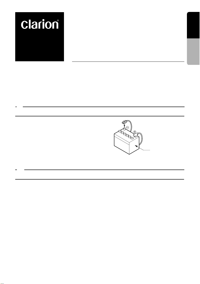
3. Be sure to disconnect the battery “v” termi-
nal before starting. This is to prevent short
circuits during installation. (Figure 1)
Car battery
English
Installation and Wire
connection manual
2. PACKAGE CONTENTS
1 Main unit
2 Tuner Amp unit
3 Manuals
Owner’s manual & Installation manual
Warranty card
Guide label for SIRIUS radio
4 Power supply lead (For the main unit)
5 Power supply lead (For the tuner amp
unit)
Connection cord (Main unit ↔ Tuner amp unit)
6
7 Antenna extension cord
Bag for accessories of the main unit (No. 1)
8
Flat head screw (M5 × 8) ............................ 4
Sems hexagonal bolt (M5× 8) ..................... 5
Electro tap
Machine screw (M4× 3)............................... 4
Figure 1
Bag for accessories of the main unit (No. 2)
9
Hook plate................................................... 2
Cord clamp
Rubber cap
Special screw
0 Bag for accessories of tuner amp unit
Maunting bracket......................................... 2
Canoe clip ................................................... 4
Machine screw (M4 × 8).............................. 4
! Universal mounting bracket
@ Remote control unit
# Battery
(for remote control unit)
$ Outer Escutcheon
% DCP Case
VRX935VD 65
English
T
NNT
NT
3. GENERAL CAUTIONS
1. Do not open the case. There are no user serviceable parts inside. If you drop anything
Installation and Wire
connection manual
into the unit during installation, consult your
dealer or an authorized CLARION service
centre.
4. CAUTIONS ON INSTALLATION
1. Prepare all articles necessary for installing
the main unit before starting.
2. This model is used with the LCD panel slid
forwards (shell loading system). On some
types of cars, the LCD panel may touch the
dashboard or shift lever, in which case it cannot be installed. Check that the set will not
hamper operation of the shift lever before
choosing the place of installation.(Figure 2)
Dashboard
Shift lever
(check that it does not
touch the LCD.)
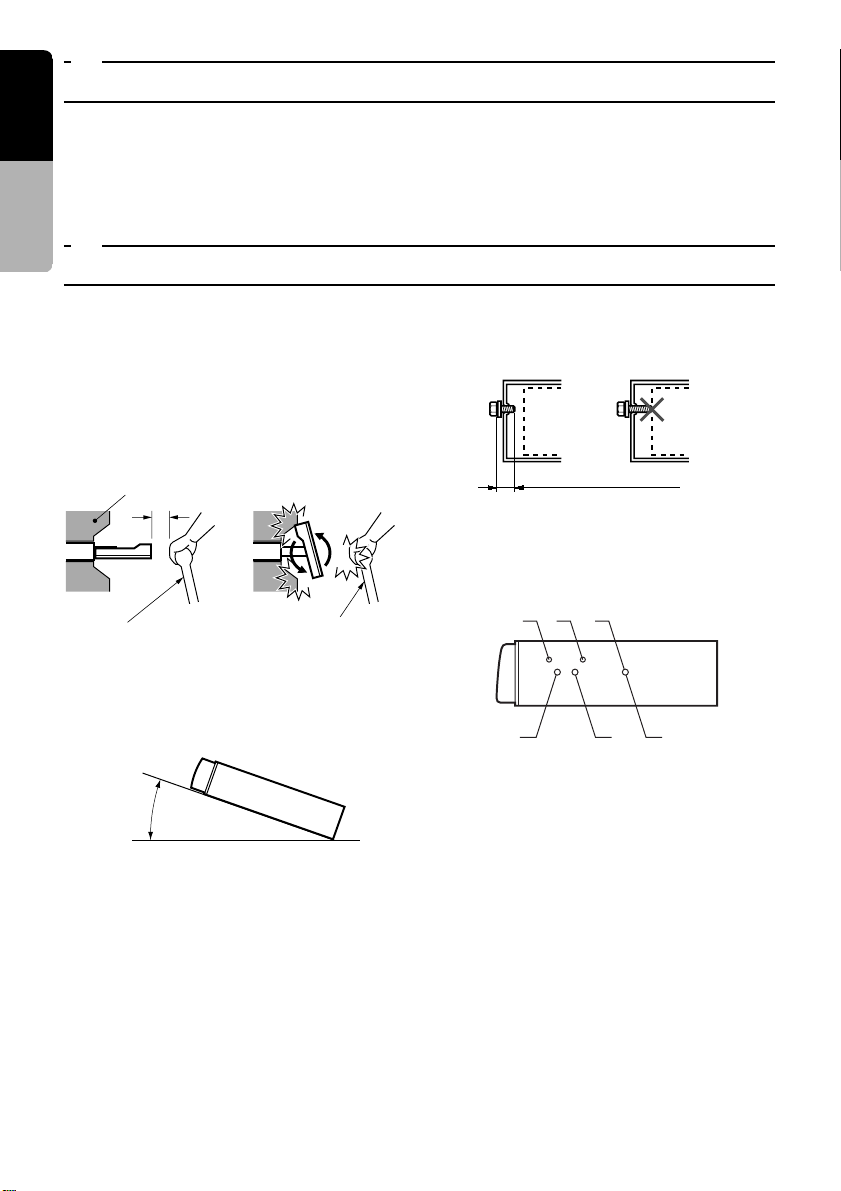
3. Install the unit within 30° of the horizontal
plane. (Figure 3)
Figure 2
Shift lever
2. Use a soft, dry cloth to clean the case. Never
use a rough cloth, thinner, benzine, or alcohol, etc. For tough dirt, apply a little cold or
warm water to a soft cloth and wipe off the
dirt gently.
5. Use the enclosed screws for installation. Using other screws can cause damage. (Figure
4)
Chassis Chassis
Damage
Max. 8 mm (M5 screw)
Figure 4
6. The source unit has mounting screw holes
for NISSAN (N marks) and TOYOTA (T
marks) vehicles.
Figure 5
Max. 30˚
Figure 3
4. If you have to do any work on the car body,
such as drilling holes, consult your car dealer
beforehand.
66 VRX935VD
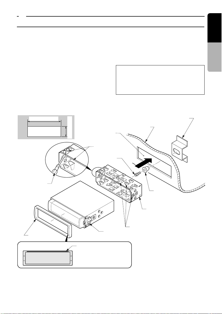
5. INSTALLING THE MAIN UNIT
■ Universal Mount
1. Place the universal mounting bracket into the
instrument panel, use a screwdriver to bend
each stopper of the universal mounting
bracket inward, then secure the stopper as
shown in Figure 6.
2. Wire as shown in Section 8.
3. Insert the main unit into the universal mounting bracket until it locks.
4. Mount the outer escutcheon so that all the
hooks are locked.
• Console opening dimensions
7-3/16" (182 mm)
Hole
2-1/16" (53 mm)
Stoppers
Special Screw
Notes:
1) Some car models require special mounting kits
for proper installation. Consult your Clarion
dealer for details.
2) Fasten the front stopper securely to prevent the
main unit from coming loose.
Instrument panel
Hole
Rear fastening hole (of vehicle)
English
Installation and Wire
connection manual
Screwdriver
Outer escutcheon
Main unit
Note:
Set the outer escutcheon so that its metallic
part on the back side
fits the upper edge of
the main unit.
Rubber cap
Universal mounting bracket
Stoppers
2-Spring
Figure 6
VRX935VD 67
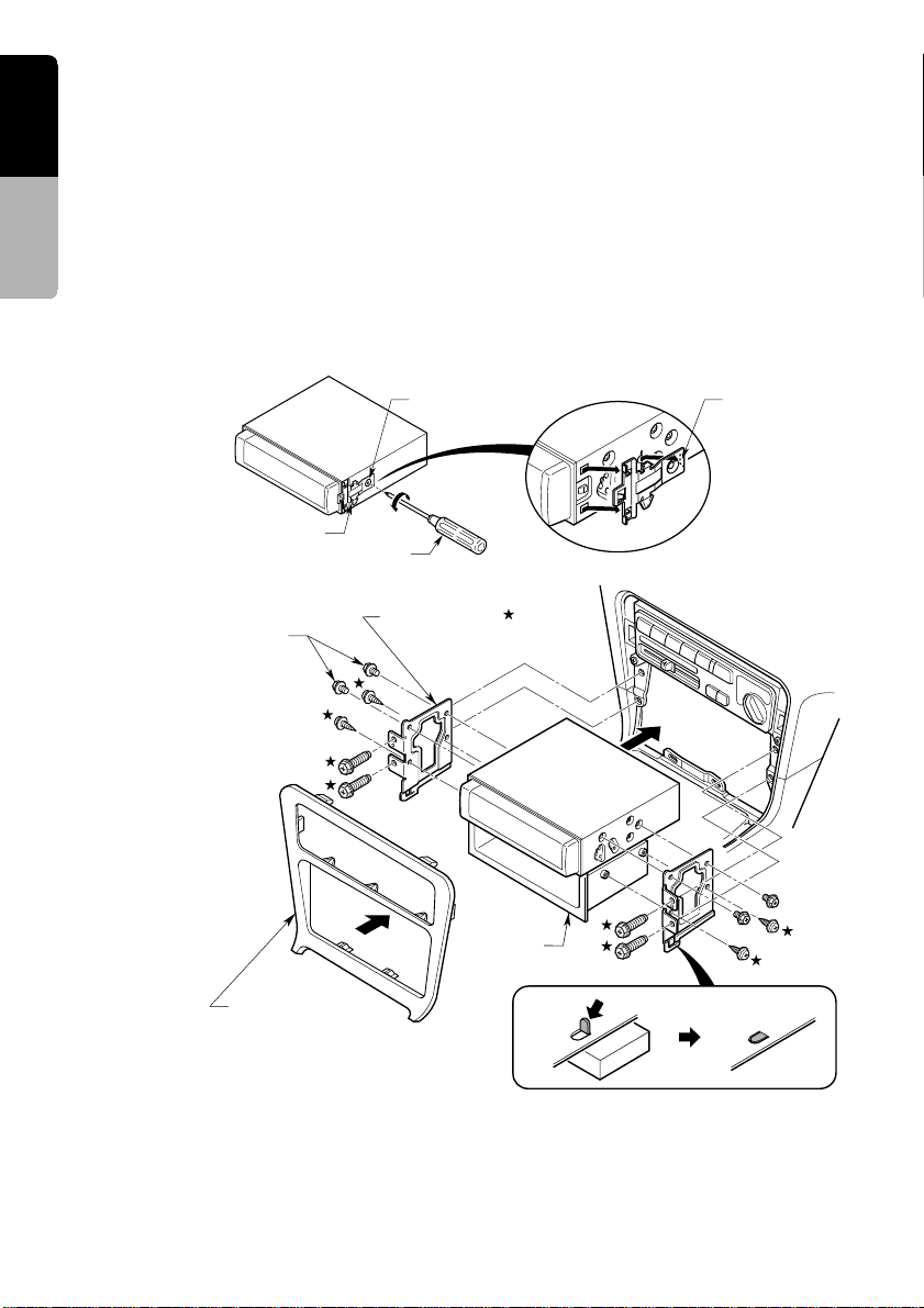
■ Fixed Mount (TOYOTA, NISSAN and other ISO/DIN equipped vehicles)
English
This unit is designed for fixed installation in the
dashboard.
If the vehicle is equipped with a factory-installed
radio, install the main unit with the parts and
Installation and Wire
connection manual
screws marked (∗). (Figure 8)
If the vehicle is not equipped with a factory-in-
stalled radio, obtain an installation kit to install
the main unit in the following procedure.
1. Remove the screws from both side of the
main unit. Then, at either side, lift the leaf
spring until the engaging claws are released
from the holes, and slide the spring to the di-
rection of arrow to remove it. Repeat the
same for the other side to remove the
springs from the both sides. (Figure 7)
2. Secure the mounting brackets to the chassis
as shown in Figure 8. Holes are pre-tapped
for TOYOTA and NISSAN vehicles; modification, such as drilling new holes, of the mounting brackets may be required for other models.
3. Wire as shown in Section 8.
4. Secure the unit in the dashboard, and then
reassemble the dashboard and the centre
panel.
Main Unit
2-Spring
Screwdriver
4-Hexagonal screw ∗ (M5 × 8)
Centre Panel (Note 1)
∗: The screws with this mark are
enclosed in this set.
★:The parts and screws with this mark
are used to install radio or included in
the installation kit.
2-Screw
Figure 7
Mounting bracket
(1 pair for the left and right sides)
Main Unit
Pocket
Note 2
Figure 8
Engagin claw
Note 1:
In some cases, the centre panel may require
some modification (trimming, filling, etc.).
68 VRX935VD
Note 2: If a hook on the installation bracket inter-
feres with the unit, bend and flatten it with
a nipper or a similar tool.
 Loading...