

Page 1
7" WIDE LCD MONITOR
AFFICHEUR À CRISTAUX LIQUIDES (LCD) COULEUR LARGE DE 7"
PANEL LCD A COLOR PANTALLA ANCHA DE 7"
VMA8582
English
Owner's manual & Installation manual
Mode d'emploi et manuel d'installation
Manual del usuario y de instlactión
Français
Español
1999/2 (D/M) ZM-7000B
All Rights Reserved. Copyright © 1999:Clarion Co., Ltd.
Printed in Japan / Imprimé au Japon / Impreso en Japón
Thank you for purchasing the Clarion VMA8582.
Nous vous remercions d’avoir acheté le Clarion VMA8582.
Muchas gracias por la adquisición del VMA8582 Clarion.
Page 2

English
English
* Please read this Owner’s manual & Installa-
tion manual in its entirety before proceeding
with wire connection and installation.
* After reading this manual, be sure to keep it in
a handy place (e.g., glove compartment).
Owner’s Manual
If you sell the motor vehicle, please leave the
manual in it so that the new owner can use it.
* Read the contents of the enclosed warranty
card and keep it with this manual.
Español
* Antes de pasar a la conexión de los cables y a
la instalación, lea detenidamente este manual
del usuario y de instalación.
* Después de haber leído este manual, guárdelo
a mano (p. ej., en la guantera).
Cuando venda su automóvil, deje en él el
manual de instrucciones a fin de que pueda
utilizarlo el nuevo usuario.
* Lea el contenido de la tarjeta de garantía
adjunta, y guárdela con este manual.
Français
* Veuillez lire entièrement le mode d’emploi et
Français
le manuel d’installation avant de procéder aux
connexions et à l’installation.
* Après avoir lu ce mode d’emploi, prenez soin
de le conserver dans un endroit pratique (par
ex: la boîte à gants).
Si vous vendez votre véhicule à moteur,
Mode d’emploi
laissez-y le manuel de façon que le nouveau
propriétaire puisse l’utiliser.
* Lisez le contenu de la carte de garantie com-
prise et conservez-la avec ce manuel.
Español
English
■
Contents
1. PRECAUTIONS 3
2. FEATURES 4
Manual de
3. CAUTIONS ON HANDLING 5
Cleaning 5
4. NAMES OF THE PARTS AND THEIR FUNC-
TIONS 6
Display unit 6
Control Box 9
5. OPERATION 10
Adjusting the Volume 10
Selecting the Screen Mode (size) 11
Dimmer 12
Picture Adjustment 15
Television Broadcast System: PAL/NTSC Setting
6.
CONNECTION OF EXTERNAL EQUIPMENT
Connection Example 19
7. TROUBLESHOOTING 22
8. SPECIFICATIONS 23
9. WARRANTY CERTIFICATE AND AFTERSERVICE 24
• Installation/Wire Connection Manual 25
Français
■
Table des matières
1. PRÉCAUTIONS 33
2. CARACTÉRISTIQUES 34
3. PRÉCAUTIONS DE MANIPULATION 35
Nettoyage 35
4. NOMENCLATURE DES TOUCHES ET LEURS
FONCTIONS 36
Module d'affichage 36
Boîtier de commande 39
5. FONCTIONNEMENT 40
Réglage du volume 40
Sélection du mode d'écran (taille) 41
Gradateur 42
Réglage de l'image 45
Système de diffusion télévisée: Rubrique PAL/NTSC
6. RACCORDEMENT D'UN APPAREIL
EXTERNE 49
Exemple de raccordement 49
7. GUIDE DE DÉPANNAGE 52
8. SPECIFICATIONS 53
9. CERTIFICAT DE GARANTIE ET SERVICE
APRÉS-VENTE 54
• Manuel d'installation/connexion 55
Español
■
Índice
1. PRECAUCIONES 63
2. CARACTERÍSTICAS 64
3. PRECAUCIONES DE MANEJO 65
Limpieza 65
4.
NOMBRES DE PARTES Y SUS FUNCIONES
Unidad de visualización 66
Caja de control 69
5. OPERACIÓN 70
Ajuste del volumen 70
Selección del modo de pantalla (tamaño) 71
Regulador de brillo 72
Ajuste de la imagen 75
18
19
Sistema de teledifusión: Ajuste de PAL/NTSC
6. CONEXIÓN DE EQUIPOS EXTERNOS 79
Ejemplo de conexión 79
7. SOLUCIÓN DE PROBLEMAS 82
8. ESPECIFICACIONES 83
9. CERTIFICADO DE GARANTÍA Y SERVICIO
POSVENTA 84
•
Manual de instalación/Conexión de cables
48
66
78
85
2 VMA8582 (U)
Page 3
1. PRECAUTIONS
English
1. This set is for use in DC 12V, negativ e ground
vehicles. Be sure to consult y our store of purchase or a Clarion-designated service outlet
before installing it on DC 24V cars.
2. Do not operate the set in ways other than
described in this guide. Doing so may damage it.
3. Safety first! For rear seat use only. Do not
install on dashboard or anywhere else that
would permit monitor to be viewed by the
driver. Monitor must not be located in the
motor vehicle at any point f orward of the back
of the front seats. Monitor m ust nev er be used
in any manner that will distract driver or interfere with driver’s safe operation of the motor
vehicle.
4. Be careful not to run down the car battery
8. Do not let lit cigarettes or other hot objects
touch the set. Doing so may damage or deform the cabinet.
9. Do not let the set become hot. If the temper ature in the car is high or if the set has been
exposed to direct sunlight and is hot, lower
the temperature before using it.
(The LCD panel will work properly within a
temperature range of 0 to 40 ˚C.)
10.In extremely cold temperatures, the movement
of the picture may be slow and the picture may
be dark, but this is not a malfunction. The set
will work normally once the temperature increases.
11.Small black and shiny dots inside the liquid
crystal panel are normal for liquid crystal products.
while using the set with the car stopped.
5. For safety, install the set in a position at which
it cannot be seen by the driver.
6. Do not disassemble or modify the set. Doing
so may damage it.
7. Keep drinks and drops from umbrellas away
from the set. Water may damage the internal
circuitry.
This equipment has been tested and found to comply with the limits for a Class B digital device,
pursuant to Part 15 of the FCC Rules. These limits are designed to pr ovide reasonable protection
against harmful interference in a residential installation. This equipment generates, uses, and
can radiate radio frequency energy and, if not installed and used in accor dance with the instructions, may cause harmful interference to radio comm unications. However , there is no guarantee
that interference will not occur in a particular installation. If this equipment does cause harmful
interference to radio or television reception, which can be determined b y turning the equipment
off and on, the user is encouraged to consult the dealer or an experienced radio/TV technician
for help.
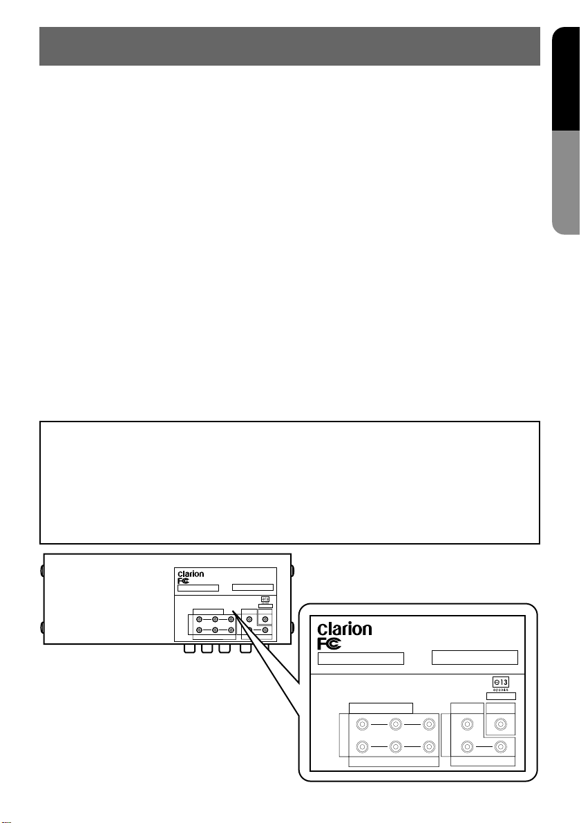
Owner’s Manual
MODEL NO.
Assembled From Tested Components (Complete System Not Tested)
FOR HOME OR CAR USE
Clarion Company.Limited.
This device complies with Part 15 of the FCC Rules. Operation is subject to the
following two conditions : (1) This device may not cause harmful
interference,and (2) This device must accept any interference received,
VIDEO / CAMERA
1
2
AV INPUT
VIDEO
L-AUDIO-R
VIDEO
AV OUTPUT
ZM-7000
MADE IN JAPAN
7WMPALA
NO USE
L-AUDIO-R
MODEL NO.
Assembled From Tested Components (Complete System Not Tested)
FOR HOME OR CAR USE
Clarion Company.Limited.
This device complies with Part 15 of the FCC Rules. Operation is subject to the
following two conditions : (1) This device may not cause harmful
interference,and (2) This device must accept any interference received,
including interference that may cause undesired operation.
VIDEO / CAMERA
1
2
AV INPUT
VIDEO
L-AUDIO-R
ZM-7000
MADE IN JAPAN
VIDEO
AV OUTPUT
L-AUDIO-R
VMA8582(U) 3
7WMPALA
NO USE
Page 4
English
USE OF CONTROLS, ADJUSTMENTS, OR PERFORMANCE OF PROCEDURES OTHER THAN
THOSE SPECIFIED HEREIN, MAY RESULT IN HAZARDOUS RADIATION EXPOSURE.
THE COLOR LCD MONITOR SHOULD NOT BE ADJUSTED OR REPAIRED BY ANYONE EXCEPT PROPERLY QUALIFIED SERVICE PERSONNEL.
Owner’s Manual
INFORMATION FOR USERS:
CHANGES OR MODIFICATIONS TO THIS PR ODUCT NOT APPRO VED BY THE MANUFACTURER
WILL VOID THE WARRANTY AND WILL VIOLATE FCC APPROVAL.
CAUTION
WARNING
MONITOR AND TUNER MUST BE INSTALLED AND USED ONL Y IN ACCORD ANCE WITH THESE
INSTRUCTIONS. FAILURE TO DO SO MAY CAUSE DAMAGE TO THE VEHICLE OR THE MONITOR, MAY RESULT IN AN ACCIDENT, AND MAY VIOLATE THE LAW. CLARION DISCLAIMS
ANY LIABILITY FOR ANY DAMA GES THAT MAY RESULT FR OM A FAILURE T O INSTALL AND
USE THIS UNIT AS STATED IN THESE INSTRUCTIONS.
2. FEATURE
● 7" wide-screen color LCD panel
The 7" TFT active matrix color LCD panel delivers striking images.
● Bright, clear screen
The color LCD panel has 336,960 pixels for
superior image resolution.
● Switchable screen size
The display can be switched between four
screen sizes: normal, full-wide, wide and cinema.
4 VMA8582 (U)
● Video input terminal
The display can be used to enjoy video images even if no TV tuner is connected.
● Built-in auto dimmer
Automatically adjusts the screen brightness
according to the ambient brightness.
● Expansion AV output terminal
Enables the installation of another monitor in
the rear seat.
Page 5

3. CAUTION ON HANDLING
For a longer service life, be sure to read the following cautions.
• Don’t allow any liquids on the set from drinks,
umbrellas etc. Doing so may damage the internal circuitry.
• Do not disassemble or modify the set in any
way. Doing so may result in damage.
• Do not let cigarettes burn the display. Doing
so may damage or deform the cabinet.
Cleaning
• If a problem should occur, have the set inspected at your store of purchase.
• Do not hold on the LCD panel when adjusting
the angle of the LCD panel. Doing so ma y damage it.
English
Owner’s Manual
• Cleaning the cabinet
Use a soft, dry cloth and gently wipe off the
dirt.
For tough dirt, apply some neutral detergent
diluted in water to a soft cloth, wipe off the dirt
gently, then wipe again with a dry cloth.
Do not use benzine, thinner, car cleaner, etc.,
as these substances may damage the cabinet
or cause the paint to peel. Also, leaving rubber of plastic products in contact with the cabinet for long periods of time may cause stains.
• Cleaning the LCD panel
The LCD panel tends to collect dust, so wipe
it off occasionally with a soft and dry cloth.
The surface is easily scratched, so do not rub
it with hard objects.
VMA8582(U) 5
Page 6
English
4.
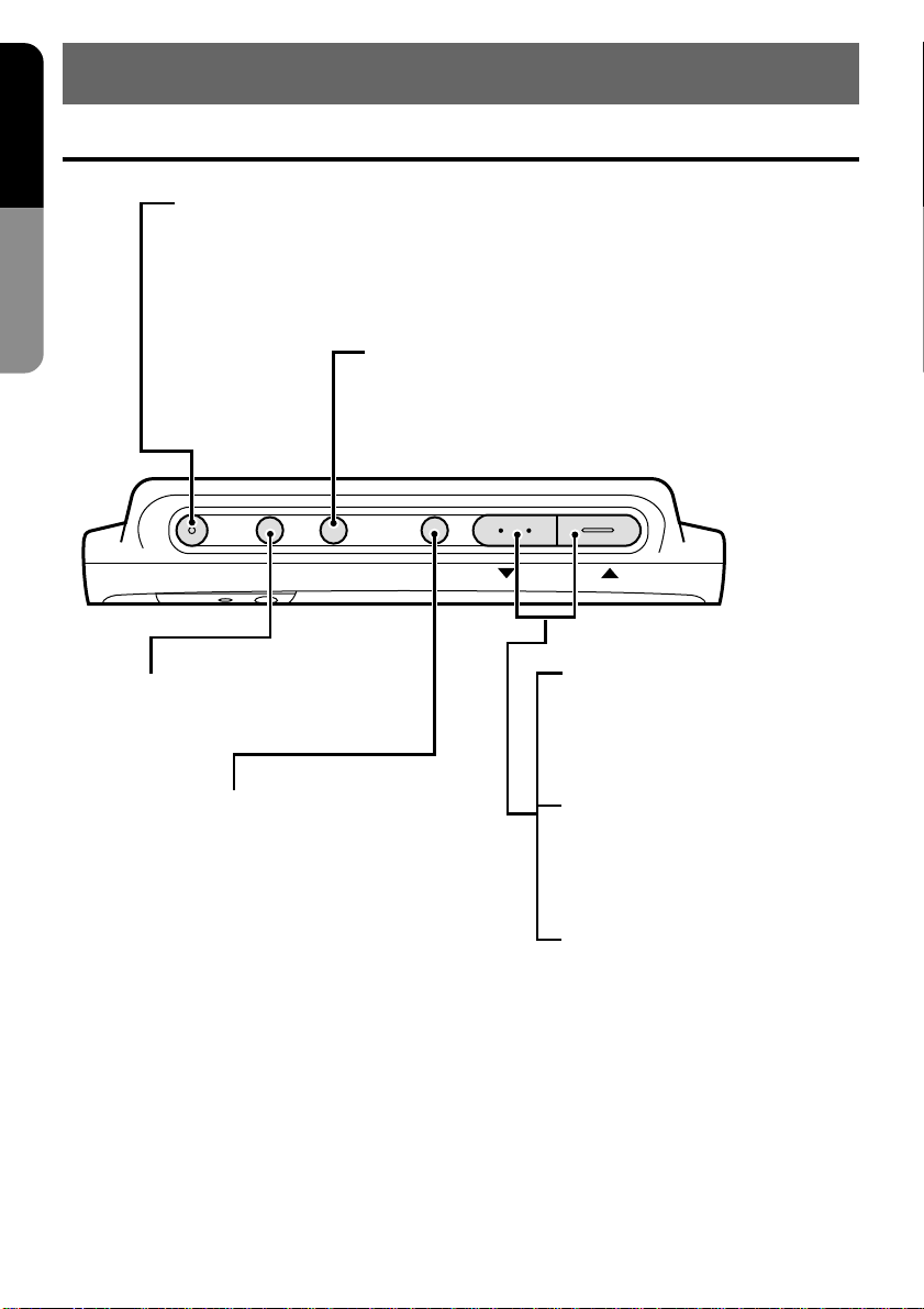
Display Unit
Names of the Parts and their Functions
Owner’s Manual
POWER button
Turns the power on and off.
WIDE button
Switches the screen display mode.
POWER FUNC WIDE MENU
FUNC button
Switches the input source.
MENU button
Displays the adjustment screen,
selects menus, and sets the adjustment.
In normal mode:
Increases and decreases the
volume of the built-in speaker
(on the back panel).
In menu setting mode:
Selects a menu.
6 VMA8582 (U)
In adjustment mode:
Adjusts the level and
switches the setting.
Page 7
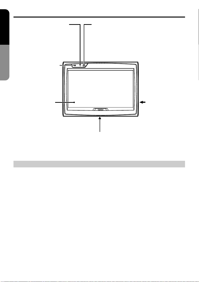
Display Unit
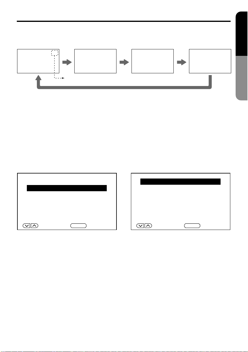
FUNC button
Switches the input source.
Each time this button is pressed, the video mode changes in the following sequence.
AV1
AV1
FUNC FUNC FUNC
Video mode display (❈)
AV2
AV2
RGB
AV1
RGB
AV2
Note:
● The on screen display disappears after 3 seconds.
❈ Upper part of the video mode display (pink color): Input source appearing on the screen of this
monitor.
❈ Lower part of the video mode display (yellow color): Input source outputting to the expansion AV
output terminal (second monitor).
MENU button
Displays the adjustment screen, selects menus, and sets the adjustment.
English
Owner’s Manual
RGB
<In and mode>
AV1
RGB
AV2
AV1
<In and mode>
AV1
AUTOMATIC DIMMER
AUTOMATIC DIMMER
DIMMER SELECT
INPUT SELECT
PICTURE MENU
END
DOWN/UP SELECT
❈ In menu setting mode: Selects a menu and sets an adjustment.
MENU
DIMMER SELECT
INPUT SELECT
PAL/NTSC SELECT
PICTURE MENU
END
AV2
AV2
DOWN/UP SELECT
MENU
VMA8582(U) 7
Page 8
Display Unit
English
Owner’s Manual
STAND BY (R), ON(G)
When the power is
turned off..........red color
When the power is
turned on..........green color
Dimmer sensor
When AUTOMATIC DIMMER is selected in
dimmer setting, the brightness of the screen is
adjusted automatically according to the
ambient brightness.
Receiver for remote
control unit
Built-in speaker
(on the back panel)
Terminal to which
cables from the
control box are
connected. (on the
right side of the
monitor)
The screw hole is provided to install a TV stand at the bottom of this monitor.
(1/4 inch unified screw thread, 4.5 mm of maximum length)
CAUTION
Precautions on handling of the LCD panel
• Do not leave the monitor on the dashboard with the LCD panel facing upwards. (Range of storage
temperature: -20˚C to +80˚C)
When the temperature is high or low , chemical changes occur in the LCD panel, resulting in damage
to the monitor.
• Since the LCD panel has been specially processed, the fingerpr ints will remain on the panel and
stand out if you touch the panel. Avoid touching the panel as much as possible. Also avoid pushing
the panel.
• When temperature becomes low, the picture does not appear or sometimes it takes time to appear.
On occasion, the picture motion seems to be different from that at normal temperature and the
picture quality deteriorates. These phenomena are not a malfunction. (Range of operating temperature: 0˚C to +40˚C)
• On the panel red dots, blue dots and green dots are found. This is peculiar to the LCD panel and it is
not a malfunction.
[The LCD panel has been designed and manufactured using a highly developed precision technology and has a 99.99 % or more effective pixels. However, note that 0.01 % of pixels are defective
and always light.]
8 VMA8582 (U)
Page 9

Control Box
Note:
The characters other than “POWER”, “DISPLAY
UNIT” and “RGB” are not marked on the control
box. The y are printed on the label located on the
top of the unit.
AV INPUT (AV1) terminal
This is used to connect a car video player,
video camera or rear view camera, etc.
English
Owner’s Manual
This terminal is not used currently.
POWER DISPLAY UNIT
RGB
AV INPUT (AV2) terminal
This is used to connect a TV tuner, car video
player or video camera, etc.
Expansion terminal (RGB)
Display unit connector (DISPLAY UNIT)
This is used to connect a display unit.
Power connector (POWER)
This is used to connect the power source cord.
Expansion AV output terminal
This is used to connect a
second monitor.
VMA8582(U) 9
Page 10

English
5. OPERATION
Adjusting the volume
Adjusting the volume of the built-in speaker
Owner’s Manual
POWER FUNC WIDE MENU
Decreases the volume.
SPEAKER VOLUME
30
Sound volume (0 to 60 level)
Increases the volume.
Screen display
10 VMA8582 (U)
Page 11

Selection of the screen mode (size)
The following screen display modes are supported: normal, full wide, wide and cinema.
English
Notes:
• Various screen display modes are av ailable on
this monitor.
If you select the screen display mode which is
different from the image ratio of software, such
as a TV program, it diff ers in appearance from
the original image. Please keep this in mind
and select the appropriate screen display
mode.
• If you reduce or enlarge an image using the
screen display mode switching function (full
wide, cinema, etc.) of this monitor with profit
in mind or for any purpose of making the public watch it or listen to it, it may infringe the
rights of the author who is protected under the
copyright law.
Selecting a screen display mode
Pressing the WIDE button switches the screen display mode as follows: NORMAL→F•WIDE→WIDE-
→CINEMA→NORMAL→
❈ The screen display mode can be set for each video source.
●Normal mode
NORMAL
Picture of a normal TV program (4:3)
●Full wide mode
F WIDE
This mode enlarges a picture only horizontally and
fully to the screen edges in a balanced manner.
Owner’s Manual
●Cinema mode
CINEMA
This mode enlarges a normal picture in all, and allows
you to enjoy the picture in a larger size.
However, the upper and lower parts of the picture,
or the right and left parts of the picture will be missed.
●Wide mode
WIDECINEMA
This mode enlarges a normal picture only horizontally
and fully to the screen edges.
(This enlarges the picture in a small area in the center,
and in a large area in the proximity of the right and left
side of the screen. This enlarges the picture in a
natural manner with a lesser feeling of being out of
harmony.)
VMA8582(U) 11
Page 12

Dimmer
English
In case of auto mode
The factory default setting is auto mode.
This mode adjusts the screen brightness automatically according to the ambient brightness.
Owner’s Manual
POWER FUNC WIDE MENU
1. Press the MENU button.
Confirm that “AUTOMATIC DIMMER” is selected.
AUTOMATIC DIMMER
DIMMER SELECT
INPUT SELECT
PICTURE MENU
END
DOWN/UP SELECT
2. Press the MENU button again.
The auto dimmer (dark level) display appears .
AUTOMATIC DIMMER
–55
MENU
3. Adjust the screen brightness using the ▼ and
▲ buttons so that you can see the screen with
great ease at night time. (-60 to ±0)
AUTOMATIC DIMMER
–55
If you set the AUTOMATIC DIMMER level to ± 0,
the screen brightness does not change.
Notes:
• When the menu screen is displayed and “END”
is selected in step 1 or a further operation is
not performed for 10 seconds, the menu display disappears automatically.
• If you adjust the screen brightness so that the
screen can be seen with great ease at nighttime, the screen brightness will be adjusted
automatically from the maximum luminance to
the minimum luminance (the brightness at
which the screen can be seen with great ease
at nighttime).
(It is recommended to set the AUTOMATIC
DIMMER level at -40 to -60.)
• If you set the AUTOMATIC DIMMER level to
±0, the screen brightness level will be fixed to
the maximum luminance and the screen brightness will not change.
12 VMA8582 (U)
Page 13

In case of manual mode
The screen brightness can be adjusted manually.
POWER FUNC WIDE MENU
Dimmer
English
Owner’s Manual
1. Press the MENU button.
Select “DIMMER SELECT” using the ▼ and
▲ buttons.
Press the MENU button to execute the setting.
AUTOMATIC DIMMER
DIMMER SELECT
INPUT SELECT
PICTURE MENU
END
DOWN/UP SELECT
2. Select “MANUAL” using the ▼ and ▲ buttons.
Press the MENU button to execute the setting.
MENU
DIMMER SELECT
AUTOMATIC
MANUAL
3. Select “BRIGHTNESS” using the ▼ and ▼
buttons.
Press the MENU button to execute the setting.
BRIGHTNESS
DIMMER SELECT
INPUT SELECT
PICTURE MENU
END
DOWN/UP SELECT
4. Adjust the screen brightness to the desired
level using the ▼ and ▲ buttons. (-60 to ±0)
MENU
SELECT SET
MENU
BRIGHTNESS
–10
VMA8582(U) 13
Page 14

Dimmer
English
When switching the dimmer mode from manual mode to auto mode
Owner’s Manual
POWER FUNC WIDE MENU
1. Press the MENU button.
Select “DIMMER SELECT” using the ▼ and
▲ buttons.
Press the MENU button to execute the setting.
AUTOMATIC DIMMER
DIMMER SELECT
INPUT SELECT
PICTURE MENU
END
DOWN/UP SELECT
MENU
2. Select “AUTOMATIC” using the ▼ and ▲ buttons.
Press the MENU button to execute the setting. Refer to the section “In case of auto
mode”.
DIMMER SELECT
AUTOMATIC
MANUAL
SELECT SET
MENU
14 VMA8582 (U)
Page 15

Picture Adjustment
Note:
The picture adjustments such as “black le vel”, “contrast”, “color” and “tint” are available on this monitor .
The adjustable items differ depending on the video modes. (Refer to page 17)
POWER FUNC WIDE MENU
Example: Adjusting the black level
1. Press the MENU button.
Select “PICTURE MENU” using the ▼ and ▲
buttons.
Press the MENU button to execute the setting.
AUTOMATIC DIMMER
DIMMER SELECT
INPUT SELECT
PICTURE MENU
END
DOWN/UP SELECT
MENU
3. Adjust the black le vel using the ▼ and ▲ buttons.
BLACK LEVEL
+15
English
Owner’s Manual
2. Select “BLACK LEVEL” using the ▼ and ▲
buttons.
Press the MENU button to execute the setting.
BLACK LEVEL
CONTRAST
END
DOWN/UP SELECT
MENU
Notes:
• In the RGB screen, the “BLACK” and “CONTRAST” items are only displayed.
• If a further operation is not performed for 10
seconds, the menu display disappears automatically.
• The adjustment procedure for contrast, color
and tint is the same as that for the blac k le vel.
VMA8582(U) 15
Page 16

Picture Adjustment
English
Selecting picture adjustment items
The picture adjustments available on the monitor differ depending on each video mode. Press the
FUNC button to select the video mode.
Owner’s Manual
AV1
AV1
<In and mode>
AV1
RGB
<In and mode>
<PAL mode>
AV1
<In and mode>
AV1
RGB
AV2
BLACK LEVEL
CONTRAST
END
DOWN/UP SELECT
AV2
AV2
MENU
BLACK LEVEL
CONTRAST
COLOR
END
DOWN/UP SELECT
AV2
AV2
MENU
BLACK LEVEL
CONTRAST
COLOR
TINT
END
The “black level” and “contrast” adjustments are
possible.
The “black level”, “contrast” and “color” adjustments are possible.
The “blac k level”, “contrast”, “color” and “tint” ad-
justments are possible.
DOWN/UP SELECT
MENU
<NTSC mode>
Note:
The selection between “PAL mode” and “NTSC mode” is performed by the “PAL/NTSC SELECT” setting. (Refer to page 18.)
16 VMA8582 (U)
Page 17

Picture Adjustment
Points of adjustment (The picture adjustment can be performed in each screen.)
BLACK LEVEL
This adjustment is performed
to allow the dark portion of the
screen to be seen with ease
BLACK LEVEL
–15
❈ In connection to the installation location of the display unit and the eye level, when the light and
darkness of the screen is reversed or the screen becomes whitish, adjust the black level.
Set the black level to the “–” side. Set the black level to the “+” side.
(picture in the night and hair,
etc.)
BLACK LEVEL
+15
English
Owner’s Manual
CONTRAST
Normally set this adjustment to
the center. In order to exhibit the
difference between the lightest
CONTRAST
–15
and the darkest portion of the
screen, set the contrast to the “+”
side.
CONTRAST
+15
COLOR
Set the color to the slightly
dark color.
COLOR
–15
The color becomes paler. The color becomes darker.
COLOR
+15
TINT
Set the color so that the flesh
color appears refined.
TINT
–15
The flesh color becomes red-purplish. The flesh color becomes greenish.
Note:
Only in PAL mode
TINT
+15
VMA8582(U) 17
Page 18

Television Broadcast System: PAL/NTSC Setting
English
When a car video player, video camera or TV tuner is connected to the AV INPUT terminal (AV1 or
AV2) of the control box to input video signal, you can select the broadcast system (PAL/NTSC).
Note:
Since the factory default setting is “NTSC”, use the follo wing procedure to set the broadcast system to
PAL.
Owner’s Manual
POWER FUNC WIDE MENU
1. Press the FUNC button to switch the video
mode to and .
Press the MENU button.
Select “P AL/NTSC SELECT” using the ▼ and
▼ buttons.
Press the MENU button to execute the setting.
AV1
AV1
AV2
AV2
AUTOMATIC DIMMER
DIMMER SELECT
INPUT SELECT
PAL/NTSC SELECT
PICTURE MENU
END
DOWN/UP SELECT
MENU
2. Select “PAL” or “NTSC” using the ▼ and ▲
buttons.
Press the MENU button to execute the setting.
PAL/NTSC SELECT
PAL
NTSC
SELECT SET
MENU
18 VMA8582 (U)
Page 19

6.
CONNECTION OF EXTERNAL EQUIPMENT
Connection Example
Note:
The characters other than “POWER”, “DISPLAY UNIT” and “RGB” are not marked on the control box.
They are printed on the label located on the top of the unit.
English
Owner’s Manual
POWER DISPLAY UNIT
Rear view camera
(back-eye camera),
car video player or
video camera
Video
RGB
TV tuner, car video player or video camera
Expansion AV output
Second monitor
Notes:
• For the connection method, refer to page 29 of the “Installation / Wire Connection Manual”.
• When a video camera monitor is connected to the control box and a howling noise is heard, one of
the following countermeasures should be taken.
❈ Lower the volume of this unit.
❈ Use earphones (if the earphones ter minal is provided with the camera).
❈ Put the camera microphone away from this unit.
VMA8582(U) 19
Page 20

Setting Example
English
The “INPUT SELECT” item must be set depending on external equipment connected to the RGB
terminal or the AV INPUT terminal (AV1 or AV2) of the control box.
Owner’s Manual
POWER FUNC WIDE MENU
[RGB INPUT SELECT]
1. Press the MENU button.
Select “INPUT SELECT” using the ▼ and ▲
buttons.
Press the MENU button to execute the setting.
AUTOMATIC DIMMER
DIMMER SELECT
INPUT SELECT
PICTURE MENU
END
2. Select “NAVIGATION” or “OTHER” using the
▼ and ▲ buttons.
Press the MENU button to execute the setting.
[When a car navigation system is connected]
RGB INPUT SELECT
NAVIGATION
OTHER
DOWN/UP SELECT
Note:
Each time the MENU button is pressed, the menu
screen for setting “INPUT SELECT” changes as
follows:
[
INPUT SELECT
[
AV2 INPUT SELECT
][
][
MENU
RGB INPUT SELECT
AV1 INPUT SELECT
]
]
20 VMA8582 (U)
SELECT SET
[When any equipment other than a car navigation system is connected]
MENU
RGB INPUT SELECT
NAVIGATION
OTHER
SELECT SET
Note:
• The factory default setting is “NAVIGATION”.
When you want to use the car navigation system, use this factory default setting.
If you set the RGB INPUT SELECT item to
OTHER, the car navigation system does not
work properly.
MENU
Page 21

Setting Example
English
[AV1 INPUT SELECT]
3. Select “VIDEO” or “CAMERA” using the ▼ and
▲ buttons.
Press the MENU button to execute the setting.
[When a rear view camera (back-eye camera)
is connected]
AV1 INPUT SELECT
VIDEO
CAMERA
DOWN/UP SET
[When a car video player or video camera is
connected or when no equipment is connected]
AV1 INPUT SELECT
CAMERA
MENU
VIDEO
[AV2 INPUT SELECT]
4. Select “VIDEO” or “TV TUNER” using the ▼
and ▲ buttons.
Press the MENU button to execute the setting.
[When a TV tuner is connected]
AV2 INPUT SELECT
VIDEO
TV TUNER
DOWN/UP SET
[When a car video player or video camera is
connected or when no equipment is connected]
AV2 INPUT SELECT
TV TUNER
MENU
VIDEO
Owner’s Manual
DOWN/UP SET
Notes:
• The rear view camera (back-eye camera) must
be connected to the AV INPUT terminal (AV1
only) of the control box.
• When the gear of the car is shifted to the “back”
position, the monitor shows the image of the
rear view camera (back-eye camera).
• If “CAMERA” is selected for the AV1 INPUT
SELECT item, the monitor always shows the
image of the rear view camera (back-ey e camera).
MENU
DOWN/UP SET
Notes:
• The TV tuner must be connected to the A V INPUT terminal (AV2 only) of the control box.
• If “TV TUNER” is selected for the AV2 INPUT
SELECT item, the video system is fixed to
NTSC.
MENU
VMA8582(U) 21
Page 22

English
Troub leshooting
Please recheck the following points.
Symptom
Red dots, blue dots or green dots are
Owner’s Manual
found on the panel.
Sound is heard but no picture appears.
No sound heard and no picture appears.
No sound heard from the speaker.
Dark screen.
The light and darkness of the screen
are reversed.
Whitish screen.
Pale color
Bad tint
The picture flows.
The picture becomes black and white
(monochrome).
Remedy
This symptom is peculiar to a LCD panel. This is
not a malfunction.
The LCD panel has been designed and manufactured using a highly developed precision technology and has a 99.99 % or more effective pixels. However, note that 0.01 % of pixels are defective and always light.
• Did you connect the parking brake input lead
(orange color)?
• Did you pull up the parking brake?
[FUNC button]
• Is the unit engaged in video input screen mode?
[Adjustment of the speaker volume]
Is the volume set to minimum?
[Brightness and black level]
Are they adjusted properly?
[Color depth and tint]
Are they adjusted properly?
• Check the sub-section “Setting Example” in the
section “6. CONNECTION OF EXTERNAL
EQUIPMENT”.
• Check the sub-section “Television Broadcast
System: PAL/NTSC Setting”.
Reference page
8
30, 31
6, 7
10
15~17
15~17
20~21
18
22 VMA8582 (U)
Page 23

8. SPECIFICATIONS
English
General
Model No.: VMA8582 (with TV stand)
Type: Liquid crystal color monitor unit
Power supply voltage: DC 13.2V (exclusively for
a 12-volt car)
Power consumption: 12 W (1.3 W at stand-by)
Operating temperature range: 0˚C to +40˚C
Storage temperature range: -20˚C to +80˚C
Control Box
Connection terminals: ACC power source input
External dimensions :
Mass : 1.03 ±0.11lb (470 ±50g)
1-1/2"
(37.5mm)
2-13/16"
(71.2mm)
: Rear view camera (back-
eye) interrupt input
: Parking brake signal input
: RGB input terminal
: AV input 1, 2 terminal
: AV output terminal
7-11/16" (W) ✕ 2-13/16" (H) ✕
1-1/2" (D)
196mm✕71.2mm✕37.5mm
7-11/16"
(196mm)
Display Unit
Liquid crystal panel : 7"
Screen dimensions : Width: 6-1/8" (156mm)
Number of pixels : 336,960 pixels
Effective pixel ratio : 99.99 % or more
Display method : Transmission type TN liq-
Video system : Compatible with NTSC,
Display method : TFT (thin-film transistor)
Applied light source : U-type cold-cathode tube
Audio output :1 W
Speaker : 4 cm cone type........1
External dimensions : 7-1/8" (W) ✕ 5-1/8" (H) ✕
Mass : 1.25 ±0.11lb (570 ±50g)
5-1/8"
(130.5mm)
Height: 3-7/16" (87mm)
Diagonal display size: 7"
(178mm)
234 (vertical) x
480 (horizontal) x 3
uid crystal display
PAL-50 and PAL-60
active matrix
(edge light system)
1-5/16" (D)
181mm✕130.5 mm✕34 mm
Owner’s Manual
7-1/8"
(181mm)
1-5/16"
(34mm)
VMA8582(U) 23
Page 24

English
9.
WARRANTY CERTIFICATE AND AFTER-SERVICE
• First consult the store of purchase about the
repair, handling and maintenance of this product.
• When you encounter problems because you
Owner’s Manual
have just relocated or this product was receiv ed
as a gift, consult the “repair service center” on
its repair. For other inquiries, consult the “customer service center”.
■ Warranty card (attached separately)
You should ensure that the store of purchase
filled required items such as the date of purchase, name of the store, etc. After reading in
detail, the warranty card should be stored awa y
carefully.
Warranty period: 1 (one ) year from the date
of purchase
■ When repair is required
Recheck the product to see if it has a breakdown, according to the table on page 22. If
breakdown persists, switch off the power and
call the store of purchase.
• During the warranty period, the store of purchase will repair the defective product within
the limits of warranty. You should deliver the
defective product with the warranty card.
• If the warranty expires, performance can be
maintained through repair. Repairs can be
done for a fee if the customer so desires. Ho wever, the shortest storage period of performance parts for repair is 8 (eight) years after
the end of manufacturing. (Performance parts
are the critical parts which are required for
maintenance of the product functioning.)
On fluorescent tubes
The fluorescent tubes used for this product have
an expected life span. Beyond the life span, the
fluorescent tubes do not function. In this case,
they should be replaced with new ones.
Expectancy of life span: about 6 (six) to 7
(seven) years (about 10, 000 hours) with use
of 4 hours per day
When the fluorescent tubes do not function and
require replacement, expert skills are necessary.
You should consult the store of purchase.
24 VMA8582 (U)
 Loading...