

Page 1
1
0
Web
Security
Appliance
303417
1
0
1
0
Cisco S170
Web
Security
Appliance
QUICK START GUIDE
Cisco S170 Web Security Appliance
1 Welcome
2 Before You Begin
3 Document Network Settings
4 Plan the Installation
5 Install the Appliance in a Rack
6 Plug In the Appliance
7 Temporarily Change Your IP Address
8 Connect to the Appliance
9 Power Up the Appliance
10 Log In to the Appliance
11 Run the System Setup Wizard
12 Configure Network Settings
13 Configuration Summary
14 You’re Done!
15 Where to Go from Here
Page 2

Revised: March 13, 2013
Part Number: 78-19643-04
1 Welcome
Thank you for choosing the Cisco S170 Web Security Appliance
(Cisco S170). The Cisco S170 helps organizations secure and
control web traffic.
This guide describes how to physically install the Cisco S170
appliance and use the System Setup Wizard to configure basic
settings. You can also refer to the “Deployment” chapter in the
Cisco IronPort AsyncOS for Web User Guide for information
about how to configure appliance settings.
2 Before You Begin
Before you begin the installation, make sure that you have the
items needed. The following items are included with the Cisco
S170 Web Security Appliance:
• Quick Start Guide (this guide)
• Rails and adaptor kit
• Power cable(s)
• Ethernet cable for connecting the appliance to your
network
• Regulatory Safety and Compliance Information
You will need to provide the following items yourself:
• Rack cabinet enclosure (if rack-mounting the appliance)
• Phillips-head screwdriver for assembling rails
• 10/100 Gigabit Base-T TCP/IP LAN
• Desktop or laptop computer
• Web browser (or SSH and terminal software)
• Network and administrator information for the “Document
Network Settings” section on page 3 and “go live”
configuration
2
Page 3

3 Document Network Settings
Before you begin, write down the following information about
your network and administrator settings.
Deployment Options
• Web Proxy
–
Transparent with L4
–
Switch Transparent with
WCCP Router
–
Explicit Forward Proxy
• L4 Traffic Monitor
–
Simplex tap/Span
port
–
Duplex tap/Span
port
Network Context
Is there another proxy on the
network:
Other Proxy IP Address:
Other Proxy Port:
Yes
Network Settings
Default System Hostname:
DNS Servers: Use the Internet root DNS
servers.
Use the following DNS
servers (maximum 3):
1.
Network Time Protocol (NTP)
Server:
Time Zone Region:
Time Zone Country:
Time Zone GMT Offset:
2.
3.
3
Page 4
Interface Settings
Management Port
IP Address:
Network Mask:
Hostname:
Data Port (Optional, see Note)
IP Address:
Network Mask:
Hostname:
Note The Web Proxy can share the management interface. If
configured separately, the Data interface IP address and
the management interface IP address cannot share the
same subnet.
Routes
Internal Routes for Management
Default Gateway:
Static Route Name:
Static Route Destination
Network:
Static Route Gateway:
Internal Routes for Data
Default Gateway:
Static Route Name:
Static Route Destination
Network:
Static Route Gateway:
4
Page 5

Transparent Routing Device
Device Type: • Layer 4 Switch or No
Device
• WCCP Router
–
Enable standard
service ID
(web-cache).
–
Router Addresses:
_________________
–
Enable router
security.
Password:
_________________
Note When you connect the appliance to a WCCP router, you
might need to configure the Web Security appliance to
create WCCP services after you run the System Setup
Wizard.
Administrative Settings
Administrator Password:
Email System Alerts To:
SMTP Relay Host: (Optional)
AutoSupport: Enable
SenderBase Network
Participation:
Enable
• Limited
• Standard
5
Page 6

Security Services
L4 Traffic Monitor: • Monitor only
• Block
Acceptable Use Controls: Enable
• IronPort URL Filters
• Cisco IronPort Web
Usage Controls
Web Reputation Filters: Enable
Malware and Spyware Scanning: • Enable Webroot
• Enable McAfee
• Enable Sophos
Action for Detected Malware: • Monitor only
• Block
IronPort Data Security Filtering: Enable
6
Page 7

T1 T2P2P1
MGMT
CONSOLE
303416
Management PC
Clients L4 Switch/
WCCP
Router
Ethernet tap
Simplex/
Duplex
Firewall Internet
4 Plan the Installation
Decide how you are going to configure the Cisco S170 Web
Security Appliance within your network.
The Cisco S170 appliance is typically installed as an additional
layer in the network between clients and the Internet.
Depending on how you deploy the appliance, you may or may
not need a Layer 4 (L4) switch or a WCCP router to direct client
traffic to the appliance.
Deployment options include:
• Transparent Proxy—Web proxy with an L4 switch
• Transparent Proxy—Web proxy with a WCCP router
• Explicit Forward Proxy—Connection to a network switch
• L4 Traffic Monitor—Ethernet tap (simplex or duplex)
–
Simplex Mode: Port T1 receives all outgoing traffic,
and port T2 receives all incoming traffic.
–
Duplex Mode: Port T1 receives all incoming and
outgoing traffic.
7
Page 8
1
0
1
0
Cisco C170
Web
Security
Appliance
50
104
F
C
40
10
303363
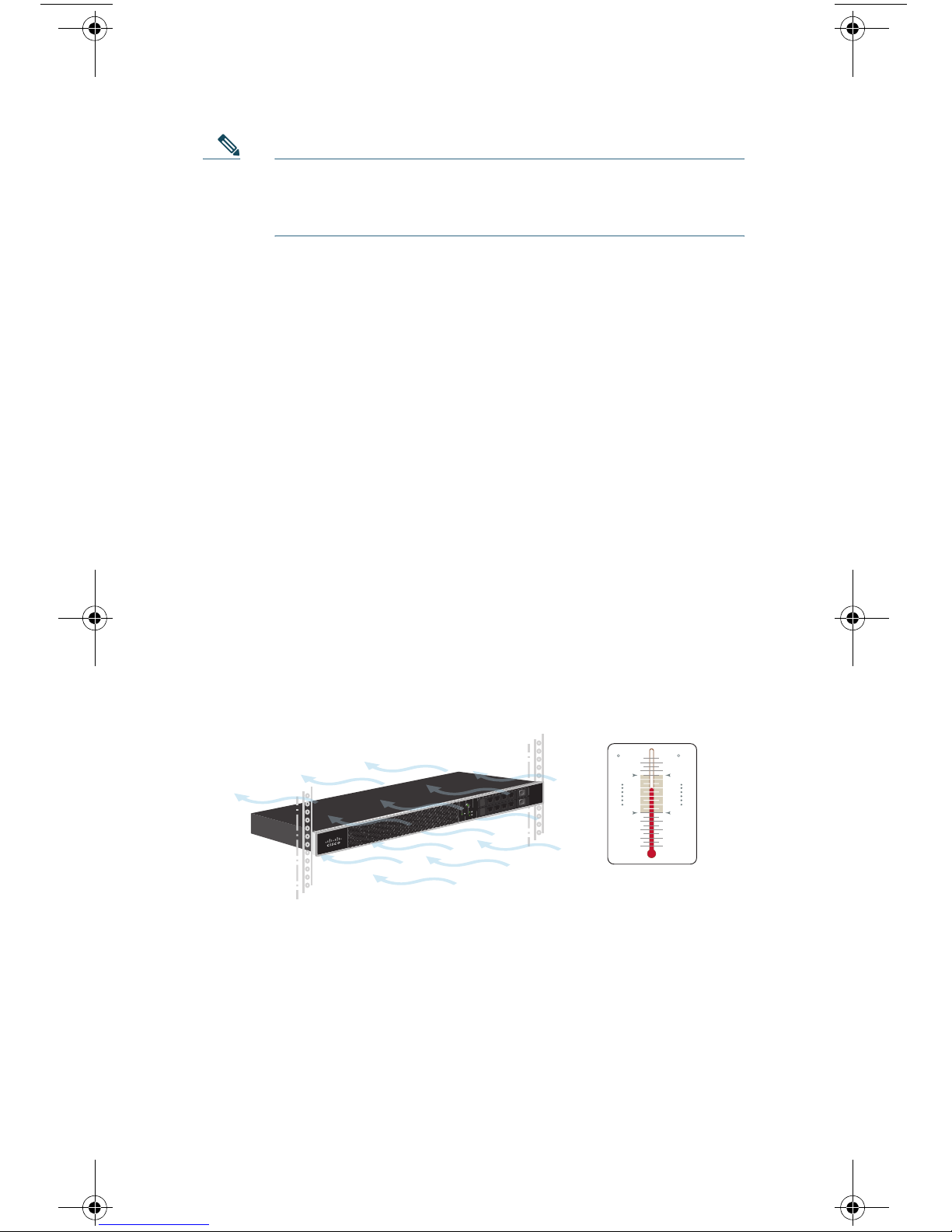
Temperature Limits
Note To monitor true client IP addresses, the L4 traffic
monitor should always be configured inside the firewall
and before NAT (Network Address Translation).
5 Install the Appliance in a Rack
Install the Cisco S170 Web Security Appliance using either the
slide rails or fixed rack mount brackets. For information about
these installation options, see the Cisco 170 Series Hardware
Installation Guide.
Appliance Placement in a Rack
• Ambient Temperature—To prevent the appliance from
overheating, do not operate it in an area that exceeds an
ambient temperature of 104°F (40°C).
• Air Flow—Be sure that there is adequate air flow around
the appliance.
• Mechanical Loading—Be sure that the appliance is level
and stable to avoid any hazardous conditions.
8
Page 9

7JZ78-003E
T1 T2P2P1
MGMT
CONSOLE
303418
Plug the Cisco S170 power
cable into an electrical outlet
6 Plug In the Appliance
Plug the female end of the power cable into the power supply on
the back panel of the appliance. Plug the male end into an
electrical outlet.
9
Page 10

7JZ78-003E
T1 T2P2P1
MGMT
CONSOLE
MGMT
303414
Management Port
7 Temporarily Change Your IP
Address
To connect to the Cisco S170 appliance, you must temporarily
change the IP address of your computer.
Note Make a note of your current IP configuration settings
because you will need to revert to these settings after
you finish the configuration.
For Windows
Step 1 Connect your laptop to the MGMT management Port
using the Ethernet cable included in the system box.
The Cisco S170 appliance uses the MGMT
management port only.
Step 2 Go to the Start menu and choose Control Panel.
Step 3 Double-click Network and Sharing Center.
Step 4 Click Local Area Connection and then click Properties.
Step 5 Select Internet Protocol (TCP/IP) and then click
Properties.
Step 6 Select Use the Following IP Address.
10
Page 11

Step 7 Enter the following changes:
• IP Address: 192.168.42.43
• Subnet Mask: 255.255.255.0
• Default Gateway: 192.168.42.1
Step 8 Click OK and Close to exit the dialog box.
For Mac
Step 1 Launch the Apple menu and choose System Preferences.
Step 2 Click Network.
Step 3 Select the network configuration with the green icon.
This is your active connection. Then click Advanced.
Step 4 Click the TCP/IP tab and, from Ethernet settings,
choose Manually from the drop-down list.
Step 5 Enter the following changes:
• IP Address: 192.168.42.43
• Subnet Mask: 255.255.255.0
• Router: 192.168.42.1
Step 6 Click OK.
11
Page 12

T1 T 2P2P1
MGMT
CONSOLE
303415
Management PC
L4 Switch/
WCCP Router
Ethernet TAP
Simplex/Duplex
8 Connect to the Appliance
Plug the Ethernet cables into the appropriate ports on the back
panel of the Cisco S170 appliance.
• The proxy ports are labeled P1 and P2.
–
P1 only enabled: When only P1 is enabled, connect it to
the network for both incoming and outgoing traffic.
–
P1 and P2 enabled: When both P1 and P2 are enabled,
you must connect P1 to the internal network and P2 to
the Internet.
• The traffic monitor ports are labeled T1 and T2.
–
Simplex tap: Ports T1 and T2; one cable for all packets
destined for the Internet (T1) and one cable for all
packets coming from the Internet (T2).
–
Duplex tap: Port T1; one cable for all incoming and
outgoing traffic.
12
Page 13

1
0
1
0
Cisco C170
Email
Security
Appliance
303362
Wait five minutes.
9 Power Up the Appliance
Power up the appliance by pressing the On/Off switch on the
front panel of the Cisco S170. After the appliance powers up, a
solid green light indicates that the appliance is operational.
10 Log In to the Appliance
You can log in to the Cisco S170 appliance using one of two
interfaces: the web-based interface or the command-line
interface.
Web-Based Interface
Step 1 For web browser access via the Ethernet port (see the
“Connect to the Appliance” section on page 12), go to
the Cisco S170 appliance management interface by
entering the following URL in a web browser:
http://192.168.42.42
13
Page 14

Step 2 Enter the following login information:
• Username: admin
• Password: ironport
303360
Note The hostname parameter is assigned during system
setup. Before you can connect to the management
interface using a hostname (http://hostname:8080), you
must add the appliance hostname and IP address to
your DNS server database.
Step 3 Click Login.
Command-Line Interface
Step 1 For command-line interface access via the serial port
(see the
access the command-line interface by SSH or a terminal
emulator using 9600 bits, 8 bits, no parity, 1 stop bit
(9600, 8, N, 1) and flow control set to Hardware.
Step 2 Initiate a session to the IP address 192.168.42.42.
“Connect to the Appliance” section on page 12),
Step 3 Log in as admin with the password ironport.
Step 4 At the prompt, run the systemsetup command.
14
Page 15

11 Run the System Setup Wizard
The System Setup Wizard starts automatically when you access
the appliance via the web-based interface (or when you run the
systemsetup command from the command-line interface) and
displays the end user license agreement (also known as the
EULA).
Step 1 Start the System Setup Wizard.
Step 2 Accept the end user license agreement.
Step 3 Enter registration information.
Step 4 Enter information from the “Document Network
Settings” section on page 3.
Step 5 Set web security settings.
Step 6 Review the configuration summary page.
Step 7 Log back in to the appliance with the username admin
and the new password that you set in the System Setup
Wizard.
The Cisco S170 Web Security Appliance uses a
self-signed certificate that may trigger a warning from
your web browser. You can simply accept the certificate
and ignore this warning.
Step 8 Write down your new administrator password and
keep it in a safe place.
15
Page 16

12 Configure Network Settings
Depending on your network configuration, your firewall may
need to be configured to allow access using the following ports.
SMTP and DNS services must have access to the Internet.
The web security appliance must be able to listen on the
following ports:
• FTP: port 21, data port TCP 1024 and higher
• HTTP: port 80
• HTTPS: port 443
• Management access: ports 8443 (HTTPS) and 8080
(HTTP)
• SSH: port 22
The web security appliance must be able to make an outbound
connection on the following ports:
• DNS: port 53
• FTP: port 21, data port TCP 1024 and higher
• HTTP: port 80
• HTTPS: port 443
• LDAP: port 389 or 3268
• LDAP over SSL: port 636
• LDAP with SSL for global catalog queries: port 3269
• NTP: port 123
• SMTP: port 25
Note If you do not open port 80 and 443, you cannot
download feature keys.
16
Page 17

13 Configuration Summary
Item Description
Management
Data
You can manage the web security appliance
from the management port (MGMT port)
by entering http://192.168.42.42:8080
or by using the IP address assigned to the
management interface after you have
completed the System Setup Wizard.
If you reset your configuration to factory
default settings (for example, by re-running
the System Setup Wizard), you can access
the management interface only from the
MGMT port (http://192.168.42.42:8080),
so ensure that you have a connection to the
MGMT port.
Also, verify that you open firewall ports 80
and 443 on your management interface.
After running the System Setup Wizard, at
least one port on the appliance is configured
to receive web traffic from the clients on the
network: M1 only; M1 and P1;
M1, P1 and P2; P1 only; or P1 and P2.
Note If you configured the web proxy in
explicit forward mode, the
applications on the client machines
must be configured to explicitly
forward web traffic to the web
security appliance’s web proxy
using the IP address configured for
data, either M1 or P1.
17
Page 18

Item Description
Traffic Monitor
Computer
Address
After running the System Setup Wizard, one
or both L4 traffic monitor ports (T1 only or
both T1 and T2) are configured to listen to
traffic on all TCP ports. The default setting
for the L4 traffic monitor is monitor only.
During or after setup, you can configure the
L4 traffic monitor to both monitor and
block suspicious traffic.
Remember to change your computer IP
address back to the original settings that
you noted in the
“Temporarily Change Your
IP Address” section on page 10.
18
Page 19

14 You’re Done!
Congratulations. You are now ready to start using your
Cisco S170 Web Security Appliance. You may wish to consider
taking some of the following steps to get more out of the
appliance:
User Policies
Use the web interface to create policies that define which users
can access which web resources as necessary.
• Identify Users—Choose Web Security Manager > Identities
to define groups of users that can access the Internet.
• Define Access Policies—Choose Web Security Manager >
Access Policies to control user access to the Internet by
configuring which objects and applications to allow or
block, which URL categories to monitor or block, and web
reputation and anti-malware settings.
You can also define several other policy types to enforce your
organization’s acceptable use policies by controlling access to
the Internet. For example, you can define policies for decrypting
HTTPS transactions and other polices that control upload
requests.
For information about configuring policies on the Cisco S170
appliance, see the “Working with Policies” chapter in the Cisco
IronPort AsyncOS for Web User Guide.
Reporting
You can view statistics about blocked and monitored web traffic
on your network by viewing reports available in the web
interface. You can view reports about the top URL categories
blocked, client activity, system status, and more.
19
Page 20

More Information
There are other features that you may want to configure for
your Cisco S170 appliance. For more information about
configuring feature keys, end user notifications, logging, and for
details about other available web security appliance features,
see the Cisco S170 Web Security Appliance documentation.
15 Where to Go from Here
Support
Cisco IronPort Support http://www.cisco.com/en/US/products/
ps11169/serv_group_home.html
U.S. Toll-Free Number 1-800-553-2447
1-408-526-7209
International Contacts http://www.cisco.com/en/US/support/
tsd_cisco_worldwide_contacts.html
Online Technical
Support and
Documentation
(login may be required)
Cisco Web Security
Appliance Support
Community
www.cisco.com/support
https://supportforums.cisco.com/com
munity/netpro/security/web
Product Documentation
Cisco S170 Web
Security Appliance
Quick Start Guide
(this document)
http://www.cisco.com/en/US/docs/
security/wsa/hw/S170_QSG.pdf
20
Page 21

Cisco 170 Series
Hardware Installation
Guide
Includes information
about LEDs, technical
specifications, and
rack-mounting
options.
Cisco Web Security
Appliance
Documentation
Includes
documentation about
configuring the
appliance features, CLI
commands, and release
notes.
Safety and Compliance
Guide
http://www.cisco.com/en/US/docs/
security/esa/hw/170Series_HW_Install
.pdf
http://www.cisco.com/en/US/products/
ps10164/tsd_products_support_series
_home.html
http://www.cisco.com/en/US/docs/secu
rity/esa/hw/SafetyAndCompliance
Guide.pdf
MIBs
AsyncOS MIBs for
Cisco Web Security
Appliance
(Related Tools section)
http://www.cisco.com/en/US/products/
ps10164/tsd_products_support_series
_home.html
21
Page 22

Obtaining Documentation and
Submitting a Service Request
For information on obtaining documentation, submitting a
service request, and gathering additional information, see
What’s
http://www.cisco.com/en/US/docs/general/whatsnew/whatsnew.
html.
Subscribe to What’s New in Cisco Product Documentation, which
lists all new and revised Cisco technical documentation, as an RSS
feed and deliver content directly to your desktop using a reader
application. The RSS feeds are a free service.
New in Cisco Product Documentation at:
Cisco and the Cisco logo are trademarks or registered trademarks of Cisco and/or its affiliates in the U.S. and other
countries. To view a list of Cisco
mentioned are the property of their respective owners. The use of the word partner does not imply a partnership
relationship between Cisco and any other company. (1110R)
Any Internet Protocol (IP) addresses used in this document are not intended to be actual addresses. Any examples,
command display output, and figures included in the document are shown for illustrative purposes only. Any use of actual
IP addresses in illustrative content is unintentional and coincidental.
© 2013 Cisco Systems, Inc. All rights reserved.
trademarks, go to this URL: www.cisco.com/go/trademarks. Third-party trademarks
22
Page 23

Page 24

Americas Headquarters
Cisco Systems, Inc.
San Jose, CA
Cisco has more than 200 offices worldwide. Addresses, phone numbers, and fax numbers are listed on
Printed in the USA on recycled paper containing 10% postconsumer waste.
78-19643-04
Asia Pacific Headquarters
Cisco Systems (USA) Pte. Ltd.
Singapore
Europe Headquarters
Cisco Systems International BV Amsterdam,
The Netherlands
the Cisco Website at www.cisco.com/go/offices.
 Loading...