


Cisco Systems 102075P Manual
GETTING STARTED GUIDE
Cisco Aironet 3602P Lightweight Access Points
1About this Guide
2Safety Instructions
3Unpacking
4Configurations
5Access Point Ports and Connectors
6Configuring the Access Point
7Mounting the Access Point
8Deploying the Access Point on the Wireless Network
9Troubleshooting
10Declarations of Conformity and Regulatory Information
11Configuring DHCP Option 43 and DHCP Option 60
12Access Point Specifications

1 About this Guide
This Guide provides instructions on how to install and configure your Cisco Aironet 3602P Access Point. This guide also provides mounting instructions and limited troubleshooting procedures.
The 3602P Access Point is referred to as the access point in this document.
2 Safety Instructions
Translated versions of the following safety warnings are provided in the translated safety warnings document that is shipped with your access point. The translated warnings are also in the Translated Safety Warnings for Cisco Aironet Access Points, which is available on Cisco.com.
Warning |
IMPORTANT SAFETY INSTRUCTIONS |
Warning
Warning
Warning
This warning symbol means danger. You are in a situation that could cause bodily injury. Before you work on any equipment, be aware of the hazards involved with electrical circuitry and be familiar with standard practices for preventing accidents. Use the statement number provided at the end of each warning to locate its translation in the translated safety warnings that accompanied this device. Statement 1071
SAVE THESE INSTRUCTIONS
Only trained and qualified personnel should be allowed to install, replace, or service this equipment.
Statement 1030
In order to comply with radio frequency (RF) exposure limits, the antennas for this product should be positioned no less than 6.56 ft (2 m) from your body or nearby persons.
Statement 339
Read the installation instructions before you connect the system to its power source.
Statement 1004
2

Warning
Warning
Warning
Warning
Caution
Caution
Note
Note
This product must be connected to a Power-over-Ethernet (PoE) IEEE 802.3af compliant power source or an IEC60950 compliant limited power source. Statement 353
Installation of the equipment must comply with local and national electrical codes.
Statement 1074
This product relies on the building’s installation for short-circuit (overcurrent) protection. Ensure that the protective device is rated not greater than:
20A. Statement 1005
Do not operate your wireless network device near unshielded blasting caps or in an explosive environment unless the device has been modified to be especially qualified for such use. Statement 245B
The fasteners you use to mount an access point on a ceiling must be capable of maintaining a minimum pullout force of 20 lbs (9 kg) and must use all 4 indented holes on the mounting bracket.
This product and all interconnected equipment must be installed indoors within the same building, including the associated LAN connections as defined by Environment A of the IEEE 802.af Standard.
The access point is suitable for use in environmental air space in accordance with section 300.22.C of the National Electrical Code and sections 2-128, 12-010(3), and 12-100 of the Canadian Electrical Code, Part 1, C22.1. You should not install the power supply or power injector in air handling spaces.
Use only with listed ITE equipment.
3

3 Unpacking
To unpack the access point, follow these steps:
Step 1 Unpack and remove the access point and the accessory kit from the shipping box.
Step 2 Return any packing material to the shipping container and save it for future use.
Step 3 Verify that you have received the items listed below. If any item is missing or damaged, contact your Cisco representative or reseller for instructions.
–The access point
–Mounting bracket (optional; selected when you ordered the access point)
–Adjustable ceiling-rail clip (optional; selected when you ordered the access point)
4 Configurations
The 3602P access point contains two simultaneous dual-band radios, the 2.4-GHz and 5-GHz 802.11n MIMO radios. For information on the regulatory domains (shown as “x” in the model numbers) see “Countries Supported” section on page 5.
External Antennas
The 3602P access point is configured with up to four external antennas and two 2.4-GHz/ 5-GHz dual-band radios. The radio and antennas support frequency bands 2400–2500 MHz and 5150–5850 MHz through a common dual-band RF interface. Features of the external dual-band dipole antennas are:
•Four RTNC antenna connectors on the top of the access point
•Four TX/RX antennas
These antennas are supported on the 3602P:
•AIR-ANT2524DB-R
•AIR-ANT2524DW-R
•AIR-ANT2524DG-R
•AIR-ANT2524V4C-R
•AIR-ANT2546V4M-R
•AIR-ANT2566P4W-R
4
Countries Supported
Click this URL to browse to a list of countries and regulatory domains supported by the 3600:
www.cisco.com/go/aironet/compliance
5 Access Point Ports and Connectors
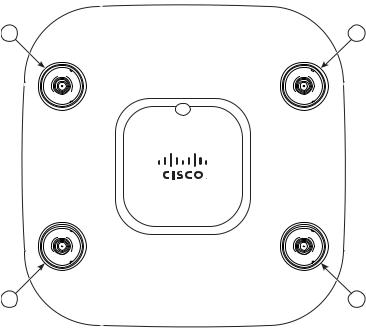
The 3602P access point has external antenna connectors and the LED indictor on the top of the model, as shown in Figure 1.
Figure 1 Access Point Ports and Connections (top)—3602E Model
1 |
2 |
A |
B |
D UAL
BAND
D UAL
BAND
|
D |
U |
D |
D |
|
AL BAN |
|
|
C |
U |
D |
D |
|
AL BAN |
|
4 3
1 |
Dual-band antenna connector A |
3 |
Dual-band antenna connector C |
|
|
|
|
2 |
Dual-band antenna connector B |
4 |
Dual-band antenna connector D |
|
|
|
|
The ports and connections on the bottom of the access point are shown in Figure 2.
5
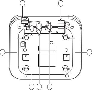
Figure 2 Access Point Ports and Connections (bottom)
1 |
5 |
6 |
6 |
|
|
|
272377 |
|
|
|
2 |
3 |
4 |
|
|
|
|
|
|
|
|
1 |
Kensington lock slot |
|
4 |
Console port |
|
|
|
|
|
|
|
2 |
DC Power connection |
|
5 |
Security padlock and hasp (padlock not |
|
|
|
|
included) |
||
|
|
|
|
|
|
3 |
Gbit Ethernet port |
|
6 |
Mounting bracket pins (feet for desk or |
|
|
|
|
|
|
table-top mount) |
|
|
|
|
|
|
6 Configuring the Access Point
This section describes how to connect the access point to a wireless LAN controller. Because the configuration process takes place on the controller, see the Cisco Wireless LAN Controller Configuration Guide for additional information. This guide is available on Cisco.com.
The Controller Discovery Process
The access point uses standard Control and Provisioning of Wireless Access Points Protocol (CAPWAP) to communicate between the controller and other wireless access points on the network. CAPWAP is a standard, interoperable protocol which enables an access controller to manage a
6

collection of wireless termination points. The discovery process using CAPWAP is identical to the Lightweight Access Point Protocol (LWAPP) used with previous Cisco Aironet access points. LWAPP-enabled access points are compatible with CAPWAP, and conversion to a CAPWAP controller is seamless. Deployments can combine CAPWAP and LWAPP software on the controllers.
The functionality provided by the controller does not change except for customers who have Layer 2 deployments, which CAPWAP does not support.
In a CAPWAP environment, a wireless access point discovers a controller by using CAPWAP discovery mechanisms and then sends it a CAPWAP join request. The controller sends the access point a CAPWAP join response allowing the access point to join the controller. When the access point joins the controller, the controller manages its configuration, firmware, control transactions, and data transactions.
Note
Note
Note
Note
For additional information about the discovery process and CAPWAP, see the Cisco Wireless LAN Controller Software Configuration Guide. This document is available on Cisco.com.
CAPWAP support is provided in controller software release 5.2 or later. However, your controller must be running release 7.1.91.0 or later to support 3600 series access points.
You cannot edit or query any access point using the controller CLI if the name of the access point contains a space.
Make sure that the controller is set to the current time. If the controller is set to a time that has already occurred, the access point might not join the controller because its certificate may not be valid for that time.
Access points must be discovered by a controller before they can become an active part of the network. The access point supports these controller discovery processes:
•Layer 3 CAPWAP discovery—Can occur on different subnets than the access point and uses IP addresses and UDP packets rather than MAC addresses used by Layer 2 discovery.
•Locally stored controller IP address discovery—If the access point was previously joined to a controller, the IP addresses of the primary, secondary, and tertiary controllers are stored in the access point’s non-volatile memory. This process of storing controller IP addresses on an access point for later deployment is called priming the access point. For more information about priming, see the “Performing a Pre-Installation Configuration” section on page 9.
7

•DHCP server discovery—This feature uses DHCP option 43 to provide controller IP addresses to the access points. Cisco switches support a DHCP server option that is typically used for this capability. For more information about DHCP option 43, see the “Configuring DHCP Option 43 and DHCP Option 60” section on page 20.
•DNS discovery—The access point can discover controllers through your domain name server (DNS). For the access point to do so, you must configure your DNS to return controller IP addresses in response to CISCO-CAPWAP-CONTROLLER.localdomain, where localdomain is the access point domain name. Configuring the CISCO-CAPWAP-CONTROLLER provides backwards compatibility in an existing customer deployment. When an access point receives an IP address and DNS information from a DHCP server, it contacts the DNS to resolve CISCO-CAPWAP-CONTROLLER.localdomain. When the DNS sends a list of controller IP addresses, the access point sends discovery requests to the controllers.
Preparing the Access Point
Before you mount and deploy your access point, we recommend that you perform a site survey (or use the site planning tool) to determine the best location to install your access point.
You should have the following information about your wireless network available:
•Access point locations.
•Access point mounting options: below a suspended ceiling, on a flat horizontal surface, or on a desktop.
Note You can mount the access point above a suspended ceiling but you must purchase additional mounting hardware: See “Mounting the Access Point” section on page 13 for additional information.
•Access point power options: power supplied by the recommended external power supply (Cisco AIR-PWR-B), a DC power supply, PoE from a network device, or a PoE power injector/hub (usually located in a wiring closet).
Note Access points mounted in a building’s environmental airspace must be powered using PoE to comply with safety regulations.
Cisco recommends that you make a site map showing access point locations so that you can record the device MAC addresses from each location and return them to the person who is planning or managing your wireless network.
8
 Loading...