

Page 1

ENGLISH
GB
Use and maintenance manual
General Index
1. FOREWORD 3
1.1 GENERAL 3
1.2 PURPOSE OF THE MANUAL 3
1.3 WHERE AND HOW TO KEEP THE MANUAL 3
1.4 MANUAL UPGRADES 3
1.5 COLLABORATION WITH USERS 4
1.6 MANUFACTURER 4
1.7 MANUFACTURER'S RESPONSIBILITY AND WARRANTY 4
1.7.1 Terms of warranty 4
1.8 TECHNICAL ASSISTANCE SERVICE 5
1.9 COPYRIGHT 5
2. MACHINE DESCRIPTION 6
2.1 PURPOSE 6
2.2 TECHNICAL SPECIFICATIONS 6
2.3 DIMENSIONS AND WEIGHTS 6
3. STARTING 7
4. CONTROL PANEL 8
5 USE OF THE WHEEL BALANCER 9
5.1 CAR/TRUCK SELECTION 9
5.2 PRESETTING OF WHEEL DIMENSIONS 9
5.2.1 Modifying set dimensions 9
5.3 MEASUREMENT RESULT 10
5.4 STATIC UNBALANCE 10
5.5 EXACT POSITIONING OF THE ADHESIVE WEIGHT BY MEANS OF THE GAUGE WITH CLIPS 10
5.6 SPLIT FUNCTION (UNBALANCE RESOLUTION) 10
5.7 OPPOSITE POSITION 11
5.8 AUTOMATIC MINIMIZATION OF STATIC UNBALANCE 11
6. SETUP 12
6.1 MENU 12
6.2 UNBALANCE OPTIMISATION 13
6.3 SELF-DIAGNOSTICS 13
6.4 CALIBRATION 13
6.5 AUTOMATIC GAUGES CALIBRATION 14
6.5.1 Rim distance gauge 14
6.5.2 Diameter gaugeE 14
7. DIAGNOSTICS 15
7.1 INCONSISTENT UNBALANCE READINGS 15
7.2 ALARM SIGNAL 15
8. MAINTENANCE 18
I 0693 - 10/10 - Rev.
Page 2

8.1 GENERAL 18
8.1.1 Introductory notes 18
8.1.2 Safety rules 18
8.1.3 Replacing fuses 18
8.1.4 To replace the driving pulley 18
9. DISPOSAL 19
9.1 DISPOSING OF THE BALANCER 19
9.2 DISPOSING OF ELECTRONICS COMPONENTS 19
10. SPARE PARTS 19
10.1 IDENTIFICATION AND ORDERING METHOD 19
11. ATTACHED DOCUMENTATION 19
Page 3

Use and maintenance manual Rev. 10-2010
1. Foreword
WARNING
ThI s mA NuAl Is AN INTeGR Al pAR T of Th e INsTAllATIoN
mAN uAl WhIc h should b e coNsulT ed coNce RNIN G sTARTING
ANd usI NG T he m AchI Ne s Afely.
ReA d cA Refu lly bef oRe coN TINu ING.
1.1 GENERAL
The machine has been constructed in conformity with the
current EC Directives and the technical standards implementing the requirements, as stated in the declaration
of conformity issued by the manufacturer and attached
to the manual.
This publication, hereinafter simply referred to as ‘man-
ual’, contains all the information required to safely use
and service the machine referred to in the Declaration of
Conformity.
This appliance, hereinafter is generically referred to as
‘machine’.
The manual addresses operators instructed on the precautions to take in relation to the presence of electric current
and moving devices.
This publication is intended for all ‘users’ who as far as
within their competence need to and/or are obliged to
give instructions to others or operate on the machine
themselves.
These persons can be identified as follows:
- operators directly involved in transporting, storing,
installing, using and servicing the machine from when
it is put on the market until when it is scrapped;
- direct private users.
The original Italian text of this publication constitutes the
only reference to resolve any interpretation controversies
related to the translation into the European Community
languages.
This publication forms an integral part of the machine
and must therefore be kept for future reference until final
dismantling and scrapping of the machine.
ENGLISH
1.2 PURPOSE OF THE MANUAL
This manual, and the installation manual, contains the
instructions required to use the machine safely and carry
out routine maintenance work.
Any calibrations, adjustments and extraordinary maintenance operations are not considered in this document as
they may only be performed by the service engineer who
must work on the machine according to the technical and
rated characteristics for which it was built.
Though it is fundamental to read this manual, it cannot
replace skilled technical staff who must be adequately
trained beforehand.
The foreseen use and configurations of the machine are
the only ones allowed by the manufacturer; do not attempt
to use the machine in a different way.
Any other use or configuration must be agreed in advance
with the manufacturer in writing and in this case an annex
will be attached to this manual.
For use, the user must also comply with the specific
workplace legislation in force in the country where the
machine is installed.
The manual also refers to laws, directives, etc., that the
user must know and consult in order to accomplish the
goals that the manual sets out to achieve.
1.3 WHERE AND HOW TO KEEP THE
MANUAL
This manual (and relative attachments) must be kept in
a safe and dry place and must always be available for
consultation.
Make a copy and keep it in the archive.
When exchanging information with the manufacturer or
the technical assistance staff authorised by the former,
quote the rating plate information and the serial number
of the machine.
This manual must be kept for the entire lifetime of the
machine, and if necessary (e.g.: damage making all or
some of it illegible, etc.) the user must request another
copy exclusively from the manufacturer, quoting the publication code indicated on the cover.
Introduction
1.4 MANUAL UPGRADES
This manual is an integral part of the machine and reflects
the state of the art at the moment it was put on the market.
The publication complies with the directives in force on
that date; the manual cannot be considered inadequate
3
Page 4
Use and maintenance manual Rev. 10-2010
as a result of regulatory updates or modifications to the
machine.
Any manual upgrades that the manufacturer may see fit to
send to users will become an integral part of the manual
ENGLISH
and must be kept together with it.
1.5 COLLABORATION WITH USERS
The manufacturer will be pleased to provide its customers with any further information they may require and will
consider proposals for improving this manual in order to
more fully satisfy the requirements it was written for.
In case of transfer of ownership of the machine,
which must always be accompanied by the use and
maintenance manual, the original user must inform
the manufacturer of the name and address of the
new user in order to allow it to send the new user
any communications and/or updates deemed to be
indispensable.
This publication is the property of the Manufacturer
and may not be fully or partly reproduced without prior
written agreement.
in this manual
- use of the machine by people who have not read and
fully understood the contents of this manual;
- use in breach of specific regulations in force in the
country of installation;
- modifications made to the machine, software and operating logic, unless authorised by the manufacturer
in writing;
- unauthorised repairs;
- exceptional events.
Transfer of the machine to a third party must also include
this manual; failure to include the manual automatically
invalidates all the rights of the purchaser, including the
terms of warranty, where applicable.
If the machine is transferred to a third party in a country with
a different language from the one written in this manual,
the original user shall provide a faithful translation of this
manual in the language of country in which the machine
will operate.
1.7.1 Terms of warranty
The Manufacturer guarantees the machines it manufacturers against all manufacturing or assembly faults for 12
(twelve) months from the date of collection or delivery.
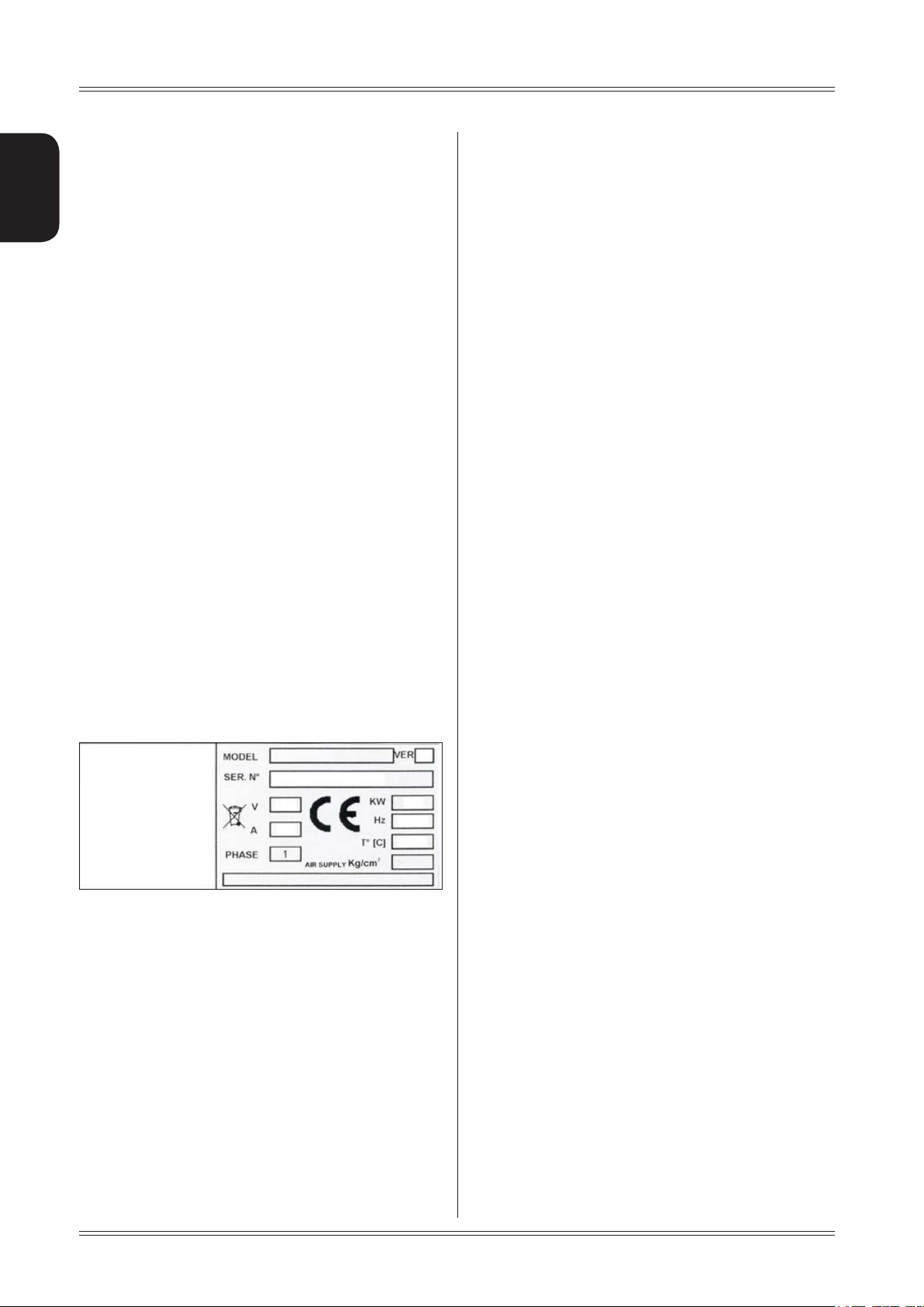
1.6 MANUFACTURER
The machine identification data is indicated on the plate
mounted on the machine.
The plate below is shown for the sake of example.
1.7 MANUFACTURER'S RESPONSIBILITY
AND WARRANTY
In order to make use of the manufacturer's warranty, the
user must scrupulously observe the precautions contained
in the manual, in particular he must:
- never exceed the limits of use of the machine;
- always constantly and carefully clean and service the
machine;
- have the machine used by people of proven capacity
and attitude, adequately trained for the purpose.
The manufacturer declines all direct and indirect liability
caused by:
- use of the machine in a different way from that indicated
The Manufacturer undertakes to replace or repair any part
which it deems to be faulty free of charge at its factory,
carriage paid.
If a Manufacturer's repairman (or a person authorised by
the same) is required to work at the user's facilities, the
relative travel expenses and board and lodging shall be
charged to the user.
The free supply of parts under warranty is always subject
to the faulty part being inspected by the manufacturer (or
a person authorised by the same).
The warranty is not extended following repairs or other
work done to the machine.
The warranty does not cover damage to the machine
deriving from:
- transport;
- neglect;
- improper use and/or use not in compliance with the
instructions in the operating manual
- incorrect electrical connections.
The warranty is invalidated in case of:
- repairs made by people who were not authorised by
the manufacturer;
- modifications that were not authorised by the manufacturer;
- use of parts and/or equipment that were not supplied
or approved by the manufacturer;
- removal or alteration of the machine identification
plate.
4
Introduction
Page 5

Use and maintenance manual Rev. 10-2010
1.8 TECHNICAL ASSISTANCE SERVICE
For any technical service operation, contact the manufacturer
directly or an authorised dealer always quoting the model,
the version and the serial number of the machine.
1.9 COPYRIGHT
The information contained in this manual may not be
disclosed to third parties. Partial or total duplication, unless authorised by the Manufacturer in writing, through
photocopying, duplication or other systems, including
electronic acquisition, is breach of copyright and can lead
to prosecution.
ENGLISH
Introduction
5
Page 6
2. Machine description
ENGLISH
Use and maintenance manual Rev. 10-2010
2.1 PURPOSE
It is a wheel balancing machine for trucks, light commercial
vehicles and cars.
It features excellent performance and is equipped with
a manual lift with sliding carriage which allows mounting
wheels of up to 250 kg on the spindle and, when tted on
the balancing machine, must not interfere with any xed part
of the machine, excluding the shaft and support adaptor.
The machine is supplied with equipment enabling the vast
majority of car and truck wheels available on the market to
be tted. Other wheels with special dimensions, geometry
and centring require special adaptors supplied on request.
The wheel balancing machine can operate without guards
since the balancing speed is only 100 rpm. It functions
properly without having to fasten it to the oor with wheels
weighing up to 160 kg; for heavier wheels, fasten it at the
points indicated.
Do not mount anything other than motorbike, car or truck
tyres on the wheel balancer.
1
3
5
4
2
6
The main features include:
▪ machine settings menu
▪ direct selection of the metrical or Anglo-Saxon system
▪ optimisation of tyre and rim unbalance.
▪ car/truck selection
▪ static programme, ALU; SPLIT; unbalance optimiza-
tion; indication of exact correction weight position; self
diagnostics; calibration.
▪ automatic minimisation of static unbalance
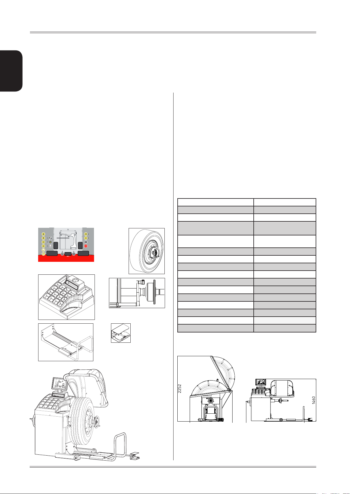
2.2 TECHNICAL SPECIFICATIONS
The following data refers to the balancer in its standard
configuration.
Single-phase power supply 115 / 230 V 50/60 Hz
Protection class IP 54
Max.power consumption 0,8 kW
Balancing speed <100 r.p.m. for cars
< 70 r.p.m. for trucks
Balancing accuracy 1 gram for cars
Cycle time for wheel
Position resolution ± 1.4 °
Average noise < 70 dB (A)
Rim width setting range 1.5” ÷ 20” or 40 ÷ 510 mm
Diameter setting range 10” ÷ 30” or 265 ÷ 765 mm
Min/max. compressed air pressure 8 ÷ 10 kg/cm
Maximum wheel weight < 250 Kg.
Machine weight 180 Kg.
10 grams for trucks
8 ÷ 20 sec.
approx. 0.8 to 1 Mpa;
approx. 8 to 10 bar;
approx. 115 to 145 psi.
2
2.3 DIMENSIONS
1. CONTROL PANEL
2. LOCK NUT
3. WEIGHT-TOOL HOLDER
4. AUTOMATIC GAUGE
5. LIFT
6. LIFT PEDAL
Machine description
6
Page 7

Use and maintenance manual Rev. 10-2010
3. Starting
ENGLISH
7. Position the wheel on the terminal with the inner part
facing the balancer;
befo Re sWIT chIN G oN The mAc hINe , mA ke s uRe ThAT A ll T he
WARNING
coNN ecTIoN s de scRI bed IN T he INsTAllATIoN c hApT eR
hAve beeN mAd e co RRec Tly.
The fol loWI NG o peRATI oNs INvo lve A poTe NTIA l RI sk foR
The ope RAToR, GIve N Th e p Rese Nce of v olTAGe o N Th e
equI pmeNT. The peR soNA l pR oTec TIve equ Ipme NT d escR Ibed
IN T he INsTAllATIoN m ANuA l m usT be W oRN ANd WoRk
musT be doN e WI Th d ue c ARe ANd ATTeNT IoN.
opeR ATIoN s mAy o Nly be peR foRm ed b y A
spe cIAl Ised Tec hNIc IAN.
Before powering the machine, carry out the following
checks:
1. check that the balancing machine touches the floor
at the three support points;
8. Firmly attach the wheel to the balancer shaft using
the lock nut.
9. In the normal version, the pedal controls a mechani
cal brake which facilitates locking the locking ring
and positioning the wheel for correction.
2. make sure that all the parts of the balancer are cor
rectly connected and fixed;
3. make sure that the parameters (voltage and frequency)
of the mains power supply are compatible with those
indicated on the rating plate of the balancer;
4. make sure the power cable is correctly connected;
5. make sure the machine shaft and flange hole are
clean.
cAuTIoN
ANy TRA ces of d IRT mAy Af fecT bAl ANcI NG A ccuR Acy.
6. To switch on the balancer press the switch on the
left-hand side of the machine.
10. At this point, you can read the tyre measurements
and perform balancing.
Starting
7
Page 8

4. Control panel
ENGLISH
Use and maintenance manual Rev. 10-2010
5
6
16
6
8
15
19
12
16
17
10
3
13
4
14
11
7
1-2 Digital readouts, AMOUNT OF UNBALANCE, inside/outside
3-4 Digital readouts, POSITION OF UNBALANCE, inside/outside
5 Indicators, correction mode selected
6 Indicators, selection made
7 Push button, unbalance reading < 5 g (25 oz)
8 Push button, car/truck selection
9 Push button, selection STATIC unbalance
10 Push button, SPLIT (unbalance spread)
11 Push button, FUNCTIONS MENU
12 Push button, menu selection conrmation
13 Push button, cycle start
14 Push button, emergency/home
15 Push button, position repeater
16 Manual dimension setting buttons
17 Push button to select grams/ounces as unit of measure for the unbalance
18 Digital display of the static unbalance value
19 Distance gauge position indication
20 Push button to select possible corrections
1
9
18
20
2
Nev eR u se T he c ouNT eRWeI GhT GRI ppeR s oR oTh eR p oINT ed o bjec Ts!
pRe ss T he b uTToN s WI Th y ouR fIN GeRs .
8
cAuTIoN
Control panel
Page 9
Use and maintenance manual Rev. 10-2010
5 Use of the wheel balancer
ENGLISH
5.1 CAR/TRUCK SELECTION
Press the button ; LED on → balancing machine
set in car mode
Press the button
set in truck mode.
; LED on → balancing machine
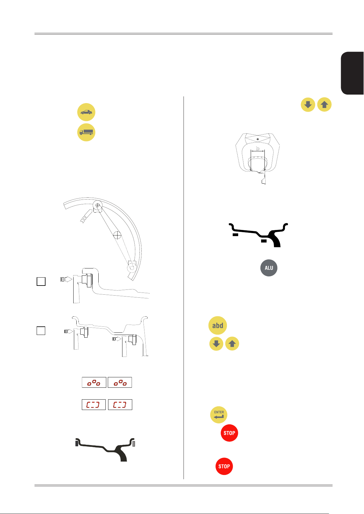
5.2 PRESETTING OF WHEEL DIMENSIONS
The balancing data is set by means of an “intelligent” au-
tomatic gauge; conrmation of the measurement and the
position appear on the display. The round part of the gauge
must rest on the rim where the weight will be positioned.
The width value (b) must be set with the buttons
The correct measurement is that which can be measured with
the compass gauge provided.
b
b) adhesive weights: make two successive measurements
on two correction planes inside the rim.
The balancing machine automatically interprets that the
correction will be made with adhesive weights and the
following appears:
For a different combination of the type or position of the
weights on the rim, use the button.
a
b
While the gauge is moving the following appears:
when the measurement has been stored:
a) standard weights: when only one measurement is
made, the machine interprets the presence of a rim with
clip-on weight correction
5.2.1 Modifying set dimensions
If the wheel dimensions have been entered incorrectly,
the parameters can be modified without repeating the
balancing spin by pressing for 2 seconds :
access parameter modication →
(select
In the case of standard weights:
(a)distance,(b)width,(d)diameter
In the case of adhesive weights:
(aI) inside distance,(aE) outside distance,(dI) inside
press
→ to recalculate the unbalance
pull out the gauge to repeat the measurement
to modify: (a) distance, (b) width, (d)
diameter
diameter,(dE) outside diameter
to conrm and go to the next parameter
or:
→
Use of the wheel balancer
to recalculate the unbalance.
9
Page 10

Use and maintenance manual Rev. 10-2010
5.3 MEASUREMENT RESULT
Unbalance display pitch:
Car = 1/5 g (.1/0.25 Oz) Truck = 10/50 g (.25/1 Oz)
When is pressed, the unbalance is displayed with
ENGLISH
pitch:
Car = 1 g Truck = 10 g
.1 Oz .25 Oz
Unbalance display threshold
Car = 5 g (.4 Oz) Truck = 50 g (2 Oz)
Inside correction
Outside correction
▪ Fit the correction weight in the specific gauge seat with
the adhesive part facing upwards
▪ Bring the wheel into correct angular position for the
plane to be corrected
▪ Lock the wheel in the correction position, by pressing
the
▪ Pull out the gauge: the approach of the weights to the cor-
rection positions is indicated by the LEDs number 19
▪ When the weight application distance has been reached
a beep is sounded (can be deactivated).
▪ rotate the gauge until the correction weight adheres to
the rim using the weight pusher.
▪ the fact that the weight application position is no longer
vertical is automatically compensated
▪ INSIDE CORRECTION POSITION
button.
After performing a balancing spin, the amounts of unbalance are shown on the digital readouts. Digital readouts
with LED lit up indicate the correct angular wheel position
to mount the counterweights (12 o’clock position).
If the unbalance is less than the threshold selected,
is displayed instead of the unbalance; with
possible to read the values below the threshold chosen.
0
it is
5.4 STATIC UNBALANCE
It is selected by pressing and is shown on the central
display. The position is indicated on the displays 3 and 4.
The value can always be displayed (see
to see the position press
.
SETUP); in this case,
5.5 EXACT POSITIONING OF THE ADHESIVE
WEIGHT BY MEANS OF THE GAUGE WITH
CLIPS
▪ Press if using the correction method with adhe-
sive weights on the inside of the rim
FI
FE
▪ OUTSIDE CORRECTION POSITION
To cancel the function, press the
button again.
5.6 SPLIT FUNCTION
(unbalance resolution)
The SPLIT function is used to position the adhesive weights
behind the wheel spokes (angle > 18°) so that they are
no longer visible (for alloy rims). Use this function in the
ALU or STATIC mode where the adhesive weight is applied inside the rim.
Enter the wheel dimensions in the ALU mode and press
START.
a. Turn the wheel to the outer side unbalance correction
position.
10
Use of the wheel balancer
Page 11

1
2
1
2
2
Use and maintenance manual Rev. 10-2010
2
1
b. Move one of the spokes to 12 o’clock (e.g.: 1) and
5.7 OPPOSITE POSITION
The normal balancing condition requires the correction
weight to be applied at the top (12 o’clock) when the
symbol is displayed:
ENGLISH
press
c. Following the direction of rotation indicated by the
position LED’s, move spoke 2 to12 o’clock and press
. The value to use for correction in position 2
is displayed.
1
d. Move spoke 1 to the correction position as indicated
by the position LED’s
If OPPOSITE POSITION is enabled, the eventual application position for the bottom weight is also indicated
next to the positioning arrows to facilitate cleaning the
rim and the relative application of adhesive weights. The
symbol used is:
5.8 AUTOMATIC MINIMIZATION OF STATIC
UNBALANCE
Initial unbalance
sx
dx
g g
sx
dx
g g
static residue
With traditional wheel
4 g
balancer
Phase shift
Possible approximations
sx
dx
g g
static residue
3 g
50°
sx
dx
g g
1 g 6 g
static residue
Choice with minimum static
unbalance
static residue
sx
g g
dx
When the OPPOSITE POSITION function is enabled (see
relative paragraph) the correction position at 6 o’clock is
also indicated, so that the operator can easily insert the
correction weight by pressing it downward.
2
1
To return to the normal unbalance indication press any
button.
INfoRmATIoN
The distance between the spokes must be at least 18°
and at most 120° (if not, the errors 24,25 or 26 appear).
Spokes with irregular or inconstant angles can be
compensated.
This program is designed to improve the quality of balancing
without any mental effort or loss of time by the operator. In
fact by using the normal commercially available weights, with
pitch of 5 in every 5 g, and by applying the two counterweights
which a conventional wheel balancer rounds to the nearest
value, there could be a residual static unbalance of up to 4
g. The damage of such approximation is emphasized by the
fact that static unbalance is cause of most of disturbances
on the vehicle. This new function, resident in the machine,
automatically indicates the optimum entity of the weights
to be applied by approximating them in an “intelligent” way
according to their position in order to minimize residual static
unbalance.
Use of the wheel balancer
11
Page 12

6. Setup
ENGLISH
6.1 MENU
This is used to personalise some balancer functions and to perform calibrations.
To access this section, press the FUNCTIONS MENU button.
See chapter on UNBALANCE OPTIMISATION
Use and maintenance manual Rev. 10-2010
diameter unit of
measure mm/inch
width unit of
measure mm/inch
start from
guard closing
approximates
1-5g 0.1-0.25oz
approximates
10-50 g 0.25-10oz
acoustic signal
activation on/off
opposite position
on/off
Static always
present
activation on/off
See chapter on AUTODIAGNOSTICS
See chapter on BALANCING MACHINE CALIBRATION
screen-saver duration
(in minutes)
Calibration of automatic RIM DISTANCE gauge
12
Calibration of automatic DIAMETER gauge
RETURN TO MEASUREMENT SCREEN
Setup
Page 13

Use and maintenance manual Rev. 10-2010
6.2 UNBALANCE OPTIMISATION
This operation is performed to reduce the static unbalance of the wheel.
It is suitable for static unbalance values in excess of 30
grams.
a. If no unbalance was measured previously, a message
appears on the display asking you to press START,
otherwise go to step b
b. Make a reference mark on the flange and the rim (using
a piece of chalk, for example).
With the aid of a tyre remover, turn the tyre on the rim
by 180°.
Ret the wheel in such a way that the reference marks
on the rim and the ange coincide.
Press START to begin reading.
ENGLISH
In the self-diagnostics sequence, all the LED’s on the panel light up for a few seconds in order to check operation.
When the LED’s go out, the machine automatically moves
on to the encoder reading phase. When the wheel is turned
manually (forwards and backwards), the display shows its
exact position. The value lies between 0 (zero) and 255.
6.4 CALIBRATION
To calibrate the machine, proceed as follows:
▪ Fit an average size wheel with a metal rim on the shaft.
Example: 6” x 15” (± 1”).
▪ Set the wheel measurements as described in paragraph
USE OF THE WHEEL BALANCER.
c. RH display: percentage reduction value
LH display: actual static unbalance value which can be
reduced by rotation
d. Mark the two positions of the rim and tyre, and turn the
tyre on the rim until the positions coincide to achieve
the optimisation shown on the display
TYRE
POSITION
RIM
POSITION
To cancel optimisation at any time, press
.
seTT ING INcoRR ecT dI meNs IoNs Would meAN Th AT The mAc hINe
cAuTIoN
Is NoT co RRec Tly cA lIbR ATed, TheRe foRe , Al l su bse queN T
meAs uRemeN Ts WIl l be I NcoR RecT uNTI l cAl IbRATI oN Is p eR-
foRm ed oNc e AG AIN WITh The coR RecT dIm eNsI oNs.
Display the SETUP menu:
1. Press to view the CALIBRATION
function.
6.3 SELF-DIAGNOSTICS
The machine can perform self-diagnostics to check the
LED’s on the control panel and make sure the encoder
reads correctly.
To perform this operation, view the SETUP menu.
Setup
2. Add a sample weight to the outer side, in any position.
Sample weight: 60 g. (2.00 .oz) for car
300 g. (10.0 .oz) for truck
.
13
Page 14

3. Shift the standard weight from the outside to the
inside keeping the same position.
ENGLISH
4. Turn the wheel until the standard weight is at the top
(12 o’clock).
5. End of calibration.
Use and maintenance manual Rev. 10-2010
INdIcATIoN
In the event of errors or faulty operation, the writing
“r.P.”: appears on the display : shift the gauge to the
rest position and repeat the calibration operation exactly
as described above. If the error persists, contact the
Technical Service Department. In the event of incorrect
input in the rim distance gauge calibration function, press
to cancel it.
6.5.2 Diameter gaugeE
Display the SETUP menu
1. Press to view the diameter gauge CALIBRATION function.
m
To cancel calibration at any time, press
.
6.5 AUTOMATIC GAUGES CALIBRATION
6.5.1 Rim distance gauge
Display the SETUP menu
1. Press to view the rim distance
gauge CALIBRATION function.
2. Leave the distance gauge in rest position and press
Place the round part of the gauge terminal on the
flange as shown in the figure and press
2. The number 352 ± 3° appears on the left display .
3. Turn the gauge downward position the round part
of the gauge terminal at 60 mm (radial distance)
from the flange as indicated in the figure; alternati
vely use one of the cones provided as shown in the
images
3. Bring the gauge in line with the adapter flange and
press
CORRECT CALIBRATION
Return the gauge to rest position.
The wheel balancer is ready for operation.
14
40 mm
4. The number 274 ± 3° should appear on the left
display. The calibration is already correct.
If not, press the button holding the gauge still at
40 mm: the number 274 appears on the left display.
Return the gauge to rest position.
Setup
Page 15

Use and maintenance manual Rev. 10-2010
7. Diagnostics
ENGLISH
7.1 INCONSISTENT UNBALANCE
READINGS
In some cases, when a wheel that has just been balanced
is repositioned on the balancer, the machine can detect
an unbalance.
This is not a machine problem but is due to faulty mounting
of the wheel on the flange. In other words, when mounting the wheel after initial balancing, it has taken another
position with respect to the balancer shaft axis.
If the wheel has been mounted on the flange with screws,
the screws may not have been tightened correctly (crisscross sequence) or the tolerances of the holes drilled in
the wheel may be too large. Small errors, up to 10 grams
(0.4 oz), are to be considered normal in wheels locked
with the relative cone: The error is normally greater for
wheels locked with screws or studs.
If, after balancing, the wheel is still unbalanced when refitted on the vehicle, this could be due to an unbalanced
brake drum or, very often, the tolerances of the holes
drilled in the rim and drum are too large. In this case,
balancing should be performed using a balancer with the
wheel mounted on the vehicle.
7.2 ALARM SIGNAL
The machine has a self-diagnostics cycle which identifies the most frequent malfunctions during the normal
work cycle.
These malfunctions are processed by the system and
shown on the display.
Diagnostics
15
Page 16

Use and maintenance manual Rev. 10-2010
ENGLISH
The INfo RmATIo N IN T he possIble Remedy col umN R equI Res W oRk T o be p eRfo Rme d by s pecI AlIs T Tec hNIc IAN s oR o TheR AuTh oR-
Ise d pe ople Wh o m usT AlWAys W oRk usI NG The peR soNA l pRoTe cTIv e equIp meNT IN dIcATe d I N Th e INsTAllATIoN mANu Al. IN some
cAs es, ThIs WoR k cA N be peR foRm ed b y A NoRm Al o peRATo R.
WARNING
ERROR CAUSE POSSIBLE REMEDY
Black The wheel balancer does not switch
on.
Err. 1 No rotation signal.
Err. 2 Speed too low during detection.
During the unbalance measurement
revolutions, the wheel speed has
fallen to below 42 rpm.
Err. 3 Unbalance too high.
Err. 4 Rotation in opposite direction.
1. Check the machine is properly connected to the mains power
supply.
2. Check the fuses on the power board and replace if necessary.
3. Replace the CPU board.
1. Use the self-diagnostics function to check the encoder.
2. Replace the encoder.
3. Replace the CPU board.
1. Make sure that a vehicle wheel is mounted on the wheel balancer.
2. Use the self-diagnostics function to check the encoder.
3. Disconnect the piezo connectors from the board and do a spin
(if no error is detected, replace the piezo sensors).
4. Replace the CPU board.
1. Check the wheel dimensions setting.
2. Check the detection unit connections.
3. Run the machine calibration function.
4. Mount a wheel with more or less known unbalance (less than
100 grams) and check the response of the machine.
5. Replace the CPU board.
1. Use the self-diagnostics function to check the encoder.
2. Check the encoder bearing/spring.
Err. 5 Guard open
The [START] pushbutton was pressed
without rst closing the guard.
Err. 7
Err. 8
Err. 9
Err. 11 Too high speed error.
Err.14
Err.15
Err.16
Err.17
Err.18
Err. 19
Err. 20 Wheel still. The wheel must remain
Err. 21 Motor on for more than 15
Err. 22 Maximum number of spins possible for
NOVRAM parameter read error 1. Switch off the machine and wait for at least ~ 1 min; re-start the
The average spinning speed is more
than
240 rpm.
Unbalance measurement error. 1. Use the self-diagnostics function to check the encoder.
still for more than one second after
START.
seconds.
the unbalance measurement has been
exceeded.
1. Reset the error.
2. Close the guard.
3. Verify the function of the protection switch.
4. Press the [START] button.
machine and check it works properly.
2. Repeat machine calibration.
3. Replace the CPU board.
1. Check functioning of the phase encoder and, in particular, the reset signal.
2. Replace the computer board.
2. Check the detection unit connections.
3. Check the machine earthing connection.
4. Mount a wheel with more or less known unbalance (less than
100 grams) and check the response of the machine.
5. Replace the CPU board.
1. Use the self-diagnostics function to check the encoder.
2. Check the connections on the power board.
3. Replace the CPU board.
1. Use the self-diagnostics function to check the encoder.
2. Check the connections on the power board.
3. Replace the CPU board.
1. Check that a vehicle wheel has been mounted on the wheel balancer.
2. Check functioning of the phase encoder and, in particular, the reset signal.
3. Replace the computer board.
16
Diagnostics
Page 17

Use and maintenance manual Rev. 10-2010
Err. 24 Distance between the spokes less
than 18 degrees.
Err. 25 Distance between the spokes
greater than 120 degrees.
Err. 26 First spoke too far from the unbal-
ance
1. The minimum distance between the spokes where the
unbalance is to be split must be greater than 18 degrees.
2. Repeat the SPLIT function increasing the distance between
the spokes.
1. The maximum distance between the spokes where the
unbalance is to be split must be less than 120 degrees.
2. Repeat the split function increasing the distance between the
spokes.
1. The maximum distance between the unbalance position and
the spoke must be less than 120 degrees.
2. Repeat the split function increasing the distance between the
spokes and the unbalance.
ENGLISH
Diagnostics
17
Page 18

8. Maintenance
ENGLISH
Use and maintenance manual Rev. 10-2010
8.1 GENERAL
cAuTIoN
befo Re peR foRm ING ANy mAINTe NANc e opeRATI oNs, mAke suRe
The mA chIN e h As bee N d Isc oNNe cTed fR om The mA INs po WeR
sup ply. AlWAys u se The peRsoN Al pRoTe cTIv e equIp meNT
INdI cATed IN The INs TAllATIo N mA NuAl .
8.1.1 Introductory notes
This machine has been designed so as not to require routine maintenance, apart from accurate periodic cleaning.
It is important to keep the machine perfectly clean in order to prevent dust or impurities from compromising the
operation of the balancer.
WARNING
The pe ople R espo NsIb le foR c leAN ING Th e AReA W heRe T he
mAchINe Is INs TAlled musT WeAR peRsoNAl pRoTe cTIve equIp meNT
IN oRd eR To W oRk IN sA feTy AN d A ccoR dING To Th e c uRRe NT
occu pATIoN Al heATh ANd sAfe Ty R eGul ATIoNs .
Specialist staff must be authorised and especially trained
concerning the dangers that may arise during operation
and the correct methods for avoiding them.
They must always work with great care and pay full attention.
If, exceptionally, the staf f removes the guards to carry out
a particular specialist technical maintenance, inspection
or repair job, they are required to put them back after
work.
After work, staff must make sure that foreign objects, in
particular mechanical pieces, tools or devices used during the operative procedure that could cause damage or
malfunctions are not left inside the balancer.
For safety , before starting work, maintenance, inspection
and repair staff must disconnect all power sources and
take all the necessary preventive safety measures.
As well as operating frequencies, the operations described
below indicate the qualifications that staff must possess
in order to perform the operation.
8.1.3 Replacing fuses
Some protection fuses are located on the power board
(see wiring diagrams) accessible by dismantling the weight
shelf). If fuses require replacement, use ones with an
identical current intensity.
As extraordinary maintenance must be performed by service
staff or, in any case, by specifically authorised and trained
people, is not dealt with in this manual.
8.1.2 Safety rules
Performing specialist activities on the equipment, particularly if the guards need to be dismounted, exposes people
to serious danger due to the presence of potentially live
parts.
The rules shown below must be scrupulously followed.
People must always use the Personal Protective Equip-
ment indicated in the Installation Manual. During activities, unauthorised people may not access the equipment
and WORK IN PROGRESS signs will be erected in the
department in such a way that they are visible from every
place of access.
8.1.4 To replace the driving pulley
The drive pulley is guaranteed by the manufacturer for
approximately 20000 runs.
A spare pulley is found inside the base (see photograph).
If necessary, to replace the pulley, proceed as follows:
▪ Remove the head and the weight holder shelf, taking
care not to damage the electric wires
▪ Remove the retaining screw on the pulley in order to
replace it
18
Maintenance
Page 19
Use and maintenance manual Rev. 10-2010
9. Disposal
cAuTIoN
The I NsTR ucTI oNs I N ThIs chAp TeR A Re INd IcATIv e. Re feR To
The Re GulATI oNs IN f oRce IN T he couN TRy Whe Re The eq uIp-
meNT Is use d.
9.1 DISPOSING OF THE BALANCER
The balancer must be disposed of after dismounting the
various parts.
For disposal operations, as well as wearing the Personal
Protective Equipment indicated in the INSTALLATION
MANUAL, refer to the instructions and diagrams in this
manual. If necessary, request specific information from
the manufacturer.
Once you have removed the various parts and components,
separate them into the different types of materials according
to the differentiated waste disposal regulations in force in
the country where the machine is dismantled.
If the various components must be stored before being
taken to the dump, make sure to keep them in a safe place
protected from atmospheric agents in order to prevent them
from contaminating the ground and the water table.
10.
Spare parts
10.1 IDENTIFICATION AND ORDERING
METHOD
The various parts can be identified using the explodeddrawings, the electrical drawings and diagrams in the machine
technical file which is archived by the Manufacturer to
which a request can be made.
For off-the-shelf parts, the technical manuals or the supplier's
original documents can be provided if the Manufacturer
deems this to be useful.
If not supplied, this documentation is also included in the
machine Technical File, archived by the Manufacturer, as
regards by Ministerial Decree 98/37/EC.
In this case, contact the Technical Service to identify the
required piece.
If the required pieces are not in any position or they can-
not be identified, contact the Technical Service, specifying the type of machine, its serial number and year of
construction.
This information is indicated on the machine identification plate.
ENGLISH
9.2 DISPOSING OF ELECTRONICS
COMPONENTS
Community directive 2002/96/EC, assimilated in Italy with legislative decree n° 151
of 25th July 2005, requires electrical and
electronic equipment manufacturers and
users to comply with a number of obligations concerning the collection, treatment,
recovery and disposal of this waste.
Please scrupulously comply with these waste disposal
regulations.
Remember that abusive dumping of this waste leads to
the application of the administrative penalties established
by current law.
Disposal – Spare parts – Attached documents
11. Attached
documentation
If not supplied, this documentation is included in the T echnical File of the machine, archived by the Manufacturer.
In this case, contact the Technical Service for detailed
information concerning the machine.
19
Page 20

 Loading...